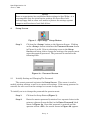
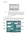
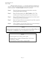
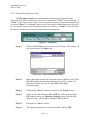
1
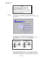
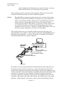
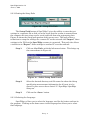
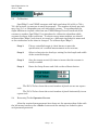
SPEC*EDGE 2000 ™ USER’S MANUAL Developed by: pogee Systems, Inc. An Employee-Owned Company TECHNICAL SUPPORT 2323 Cross Creek Drive Powder Springs, GA 30127 (770) 439-0156 E-mail: [email protected] Spec*Edge Version 3.9 June 11, 2008 Forward This manual describes the installation and usage of the Spec*Edge™ paper quality control system. Developed by Apogee Systems, Inc., in cooperation with GeorgiaPacific, Ashdown Mill, the Spec*Edge™ system was designed to support the on-going quality control and to meet the special production control needs of the communications paper industry producers. Apogee gratefully acknowledges the support, guidance in design, and many long hours of testing by Mr. Barry George and Mr. Scott Simmons of Georgia-Pacific’s Ashdown facility. Without their help, we could not have produced the Spec*Edge™ system. Spec*Edge™ was developed to provide six (6) key measurements necessary for proper measuring and evaluation of the slitting and cutting of sheets: ¦ ¦ ¦ ¦ ¦ ¦ ¦ Sheet squareness. Sharpness and curvature of the four edges of the sheet and the cut quality of single sheet edge. Absolute width and height of the sheet. Absolute location and diameter of the holes (if present) in the sheet. Corner sharpness. Hanging fibers per inch. This User’s Manual consists of four sections: Section 1 - Installation, provides the installation procedures and system support procedures of the Spec*Edge™ program. It is used to set up installations of the program, but is not needed by day-to-day operations personnel. Section 2 - Analysis, includes a description and explanation of the data, graphs and images that Spec*Edge™ produces after scanning each sheet. Section 3 - Running, describes the day-to-day operation of the Spec*Edge™ program. It includes descriptions of the various screen displays and gives the procedures for a normal scanning scenario Section 4 - Setup, covers the creation and changing of measurement specifications and Spec*Edge™ program parameters. We recognize that many of the users of this program may be new to Windows, so we have endeavored to make the program and these instructions as "userfriendly" as possible; however, we have assumed that you have a basic knowledge of your IBM-compatible PC, your scanner, and Microsoft Windows. If you find that you have questions regarding these items, please refer to the manuals distributed with those systems. If this doesn't help, Forward - i Spec*Edge Version 3.9 June 11, 2008 please call the Apogee support line at the number on the front cover of the User's Manual. Readers of this manual and users of the Spec*Edge™ program are encouraged to provide comments, suggestions, and corrections to the manual and the software directly to Apogee at the address or phone number listed on the cover of this manual. A Software Problem Report (SPR) form is included at the end of this manual to facilitate the reporting, tracking, and resolution of problems. Thank you for choosing Spec*Edge™. We assure you that it will continue to be the leading cut sheet measurement program in the industry. Microsoft Windows is a registered trademark of Microsoft Corporation. For purposes of brevity, all references to "Windows" in this manual refer to Microsoft Windows. UMAX scanners are registered trademarks of UMAX Corporation. References to UMAX throughout this manual refer to these registered products. Access, Excel and FoxPro are registered trademarks of Microsoft Corporation in the USA and other countries. References to Access, Excel and FoxPro throughout this manual refer to these registered products. Lotus and 1-2-3 are registered trademarks of Lotus Development Corporation. References to Lotus and 1-2-3 throughout this manual refer to these registered products. DBase is a registered trademark of Borland International Inc. References to DBase throughout this manual refer to this registered product. Unless otherwise noted, all names of companies and products contained herein are part of a completely fictitious scenario or scenarios and are designed solely to document the use of an Apogee Systems product. Forward - ii Spec*Edge Version 3.9 June 11, 2008 SPEC*EDGE™ INSTALLATION Section Page 1. Introduction ............................................................................................. 1 2. System Requirements and Setup .................................................... 1 3. Installation to the Hard Disk ............................................................ 1 4. Setting Spec*Edge™ to start automatically ................................ 5 5. Printers ....................................................................................................... 5 Installation. i Spec*Edge Version 3.9 June 11, 2008 SPEC*EDGE™ INSTALLATION 1. Introduction: Spec*Edge™ was developed for the paper industry to provide a user friendly, window-based system for automatically assessing the key measurements necessary for proper evaluation of the slitting and cutting of paper sheets. Spec*Edge™ was produced by Apogee Systems, Inc. It uses a flat bed scanner to digitize the image of the paper samples at a resolution of 700 or 800 dots per inch depending on the UMAX scanner being used. Spec*Edge™ is intended primarily for quality control, laboratories, research, process control on the production floor, and can be a tool in training and marketing. 2. System Requirements and Setup: The following computer configuration is the minimum necessary to effectively use the Spec*Edge™ program. ¦ ¦ ¦ ¦ ¦ ¦ ¦ ¦ ¦ 3. IBM-compatible Intel Pentium 166 based PC Microsoft Windows 95, 98, NT, 2000 or XP operating system 3.5-inch inch floppy drive CD ROM drive Keyboard Mouse 256 Mb Memory UMAX Mirage II, IIse or PowerLook 2100XL scanner Windows compatible printer Installation to the Hard Disk: Spec*Edge™ uses the standard Microsoft setup utility and is installed similarly to most other Windows programs. Spec*Edge™ is distributed on CD. Normally the D: drive on your computer is used, but another drive may be used by substituting that drive letter everywh ere the D: occurs in the following instructions. Step 1: Install the scanner software and connect the Scanner. Have the scanner running under the scanner software prior to installing the Spec*Edge™ software. Step 2: Delete any prior versions of Spec*Edge™ software and their directories prior to installing the new Version. Installation - 1 Spec*Edge Version 3.9 June 11, 2008 NOTE: To keep your old settings, copy the file <specedge setup.ses> located in the <Apogee> <SpecEdge> directory onto a floppy disk. This file contains your setting for each test. It may be copied into the new program after installation. Step 3: Place the CD in your CD Drive. The CD should start automatically and enter the setup process. Click on the Scanner that you have. If it doesn't, click on the Microsoft Toolbar click on <Start><Run>, enter your CD drive letter (d:), then click on <Browse>. Locate the folder named <Spec.Edge> . LDB Editor Spec.Edge Install Kit Disk1 Setup.exe Manual Spec*Edge Users Manual Install Kit Disk1 Manual LDB Editor Users Manual Setup.exe Spec*Edge CD Diagram Click on the <Spec.Edge> folder, click on the folder named <Install.Kit>, click on the folder named <Disk1>, then click on the file named <Setup.exe>. The setup program will begin to Installation - 2 Spec*Edge Version 3.9 June 11, 2008 load and display the following screen which is where you must select which scanner your are going to be operating. After making you choice of scanners the program will proceed to the next screens and installs just like any other windows program. Step 4: The Spec*Edge™ program requires the use of a system security plug. While this involves the installation of hardware on your computer, it allows us to distribute disks, which may be copied/backed-up at your choice; however, the program will run only on a computer with a security plug installed. This allows you to make, as many disk copies as you feel are prudent and/or to install the program on as many computers as are necessary. However, it allows Spec*Edge™ to be run on only as many computers as you have security plugs. The security plugs are easy to install and do not require the cover to be removed from your computer. They simply install onto the Parallel port on the back of your computer -- the one your printer is normally connected to. The following illustrates a typical computer: SPEC*PRINT SECURITY PLUG Back of your computer COMPUTER 25 -pin "D" fe ma le pa ralle l/printer connector 25 -pin "D" male conne cto r on t he e nd marked "c omputer" 25-pin "D" female connecto r for the printe r To the Printer Generally, the security plug should be installed between the computer and the printer cable; however, if necessary, a short extension may be placed between the computer and the plug, for example, to allow the computer to sit closer to the wall. Note that the plug is marked with arrows indicating which end must be connected to the computer. Putting the plug on the serial (usually a 9-pin male connector on the back of the computer) will not work. Generally, all printers will allow this hook-up, but other devices may create problems. Most typically, tape drives, which connect through the parallel Installation - 3 Spec*Edge Version 3.9 June 11, 2008 port, cannot work through the plug. In this case, put the plug between the tape drive and the printer, rather than between the computer and the tape drive. If you have difficulty during this installation, please call so that we can help resolve the problem. CAUTION: The security plug will fit into the SCSI connector, which was installed for your scanner. “DO NOT place the plug in this port”. Insure that the security plug is installed in the parallel port which your printer is connected. Installation - 4 Spec*Edge Version 3.9 June 11, 2008 4. Setting Spec*Edge™ to Start Automatically: The installation process placed the Spec*Edge™ systems into the Windows list of programs. To have Spec*Edge™ startup when the computer is turned on or when Windows is started, follow the normal instructions in Windows to create Spec*Edge™ as the startup program. This is accomplished by: 5. Step 1: Click your mouse once on <Start> in the Taskbar. Step 2: Click your mouse once on <Settings>. Step 3: Click your mouse once on <Taskbar…>, to open the Taskbar Properties Window. Step 4: Click your mouse once on <Start Menu Programs> near the top of the window. Step 5: Click your mouse once on <Add…> to open the Create Shortcut Window. Step 6: In the Command Line: edit field, type “C:\SpecEdge\SpecEdge.exe”. If Spec*Edge™ was installed in some other directory than “C:\SpecEdge” this field may have to be modified. Alternatively, you may wish to use the <Browse…> function to find the Spec*Edge™ executable. Step 7: Click your mouse on <Next>, a window will open showing the various Start Menu folders. Find the folder named <StartUp>, highlight it by clicking your mouse on it once. Step 8: Click your mouse once on <Next>. Step 9: Click your mouse on <Finish>. Step 10: Click your mouse on <OK>. Printers: The Windows printer environment is recommended for most users since it supports any of the hundreds of printer types which have windows drivers and produces higher print quality output. Using the Windows printer option, the normal Windows print manager functions are available. Spec*Edge™ will always use the default printer as specified in the Windows Control Panel. To change the default, click on <Start> <Settings> <Printers>, highlight the desired printer by clicking on it with the left mouse button and then select <File> <Set as Default>. See your Windows documentation for more details on these functions. Installation - 5 Spec*Edge Version 3.9 June 11, 2008 SPEC*EDGE™ ANALYSIS Section Page 1.0 Introduction ...................................................................................... 1 2.0 Spec*Edge™ Quick Analysis Screen.......................................... 1 3.0 Getting More Information ............................................................ 2 3.1 3.2 3.3 3.4 3.5 3.6 3.7 3.8 3.9 3.10 3.11 Sheet Curvature Graph........................................................... Cut Quality ................................................................................ Hanging Fibers ......................................................................... Cut Quality Distribution ........................................................ Edge Image ................................................................................ Sheet Data.................................................................................. Hole Data.................................................................................... Hole Image ................................................................................. Corner Data ............................................................................... Corner Image............................................................................. Summary Data .......................................................................... 3 4 4 6 7 8 8 9 10 10 11 4.0 Print All ................................................................................................ 12 5.0 Database ............................................................................................... 12 Analysis - i Spec*Edge Version 3.9 June 11, 2008 SPEC*EDGE™ ANALYSIS 1.0 Introduction: The Spec*Edge™ software was developed to support on-going quality control for the slitting and cutting of paper sheets. Spec*Edge™ is capable of scanning at a resolution of 700 or 800 dots per inch (DPI) depending on the UMAX scanner being used, or measuring in increments of .036 mm or .0014 in. Spec*Edge™ provides six (6) key measurements. ¦ ¦ ¦ ¦ ¦ ¦ ¦ Sheet squareness. Sharpness and curvature of the four edges of the sheet and the cut quality of a single sheet edge. Absolute width and height of the sheet. Absolute location and diameter of the holes (if present) in the sheet. Corner sharpness. Hanging fibers per inch. Spec*Edge™ is intended primarily for quality control testing, laboratories, research, process control on the production floor, and can also be a tool used in training and marketing. This section of the manual describes the analysis features of Spec*Edge™ in typical applications. The data and graphs are explained, and printed information is shown. This software is highly intuitive and requires little in the way of manuals or formal training. Indeed, the quickest way to learn it is simply to experiment on your own or with a tutor. 1.0 Spec*Edge™ Quick Analysis Screens: (Single Edge) (Full Sheet) Sample Analyzed (Figure 1) Analysis - 1 Spec*Edge Version 3.9 June 11, 2008 The analysis will be accomplished on each sheet in the order scanned as fast as the computer can do the mathematics. As each sheet is analyzed the OK/Warn/Fail lights will illuminate for the sheet that is indicated at the top right of the Operator Screen. OK/Warn/Fail Area (Figure 1): This panel indicates each of the measurements completed and the results as specified for the selected test in the setup screen. Green = OK Yellow = Warn Red = Fail Summary Buttons: Summary Button – Shows the operator the worst condition indicated on the OK/Warn/Fail panel. Clicking on this button brings up the information summary screen (Figure 1). From this screen the operator may elect to print individual scan results. 3.0 Getting More Analysis: When the operator selects the <Scan> button. Spec*Edge™ will automatically scan, analyze and report the findings, as determined by the setup specifications, to the operator. Once the scan is complete the operator may place the second sample (if required) on the scanner and click on the <Scan> button to start the second sheet in the group. The analysis will be accomplished on each sheet in the order scanned as fast as the computer can do the mathematics. As each sheet is analyzed the OK/Warn/Fail lights will illuminate for the sheet shown in Figure 1 that is indicated at the top right of the Operator Screen. Show the number of pockets (sheets) and the progress of each. Empty Scanning Complete Invalid Unknown As each sample is analyzed the operator may view the results of each measurement by: Analysis - 2 Spec*Edge Version 3.9 June 11, 2008 NOTE: The Button located on the Setup screen must be checked to allow the operator to view the graphic analysis screens Step 1: Clicking on the specific measurement button located on the left side of the Sample Analyzed (Figure 1) with the mouse button. This brings up, as an example, the following screen. Figure 2a – Curvature Graph 3.1 Curvature Graph: Once the operator has selected the graph or data to view, they may view all four sides of the sample by selecting the appropriate edge. In this case we have selected the Curvature Graph (Figure 2a). Curvature measures the amount of bend or bow in the knife blade. The operator may then view the Cut Quality (Figure 2b), Distribution (Figure 2f) and Image (Figure 2g) of the edge by selecting the appropriate plot desired. The operator may also zoom-in on a particular portion of the curvature or cut quality graph by clicking with the left mouse button on the left side of the graph where they desire to start the zoom and, while holding the left mouse button down, move the mouse pointer to the right side boundary they desire, then release the left mouse button (Figures 2c, 2d). NOTE: Each graph starts 5/8 of an inch from each side of the scanned sample. Analysis - 3 Spec*Edge Version 3.9 June 11, 2008 3.2 Cut Quality: The cut quality measurement is the standard deviation of the cut quality edge data as seen in the Distribution graph (Figure 2f). This data is the sharp deviations of the edge in inches from the edge of the paper. Often these sharp deviations are caused by individual paper fibers, which are torn so as to stick out perpendicular to the sheet edge. Figure 2b - Cut Quality Graph 3.3 Hanging Fibers: The number of times the cut quality exceeds the fail margin. This is reported as hanging fibers/inch to account for the different sized sheets. Figure 2c – Cut Quality Zoom Area Analysis - 4 Spec*Edge Version 3.9 June 11, 2008 Figure 2d shows the selected zoom area defined as between 3.25 and 3.7 inches from the left side of the plot. Figure 2d – Cut Quality Area Zoomed The operator may also elect to view the actual edge of the zoomed area by clicking on the image button with the left mouse button. Figure 2e shows the left edge between the area of 3.25” and 3.7”. Analysis - 5 Spec*Edge Version 3.9 June 11, 2008 Figure 2e – Cut Quality Zoomed Image Figure 2f – Cut Quality Distribution 3.4 Sheet Cut Distribution: The count of the cut quality data as divided into 100 equal sized bins. Most data is close to zero deviation from the edge of the paper. As the deviation increases, the number of samples at that distance decreases. Analysis - 6 Spec*Edge Version 3.9 June 11, 2008 Figure 2g – Edge Image 3.5 Edge Image: The image presented to the operator to verify the existence of an anomaly in the graphed data. 3.6 Sheet Data: (Figure 3). This display shows the average length and width of the sheet as well as the angle of the Trail-Left and Trail-Right corners. Figure 3 - Sheet Data Analysis - 7 Spec*Edge Version 3.9 June 11, 2008 3.7 Hole Data: (Figure 4). Spec*Edge™ identifies the location and size of holes in punched paper. It then compares the actual data to specified data. Spec*Edge™ will also provide an image of the actual hole by clicking with the left mouse button on <Image> (Figure 5). Figure 4 – Hole Data Analysis - 8 Spec*Edge Version 3.9 June 11, 2008 Figure 5 - Hole Image 3.8 Hole Image: The center of the hole is marked by a white “X”. The diameter specifications are drawn around the hole in concentric circles. The green circle is the nominal specification, the yellow circles are the warning (warn) limits, and the red circles are the fail limits. The green plus (“+”) marks the location where the center of the hole should be located. The yellow rectangle shows the horizontal and vertical warn limits for the center position and the red rectangle shows the horizontal and vertical fail limits. If the white “X” is inside the yellow box, then the hole position is OK. 3.9 Corner Data: (Figure 6). Spec*Edge locates the correct position for the corner of the sheet based on the slopes of the two edges of the sheet that make up the corner. It then calculates the excess or lack of paper in the corner in square Analysis - 9 Spec*Edge Version 3.9 June 11, 2008 inches. This measurement is compared to the data in the specification. Spec*Edge™ will also provide an image of the actual corner by clicking with the left mouse button on <Image> (Figure 7). Figure 6 - Corner Data Figure 7 - Right Lead Corner Image 3.10 Corner Image: The green lines on the image show the slopes of the edges as they approach the corner. From this the excess or lack of corner paper can be seen. Analysis - 10 Spec*Edge Version 3.9 June 11, 2008 3.11 Summary Data: Once the measurement is complete the operator may click with the left mouse button on the Summary Button on the Operator Screen. This is the large OK/Warn/Fail button the left of the screen. This brings up the Summary Screen as shown in Figure 8. Summary Button – Shows the operator the worst condition indicated on the OK/Warn/Fail panel. Clicking on this button brings up the information summary screen (Figure 8). From this screen the operator may elect to print individual scan results. Figure 8 – Summary Screen From this screen the operator may click with the left mouse button on the <Print> button. The summary information for that sample will automatically print on the Windows default printer. Analysis - 11 Spec*Edge Version 3.9 June 11, 2008 4.0 Print All Of The Results Of The Test: The operator may whish to see all of the results at one time. The “Print All” button does this. This may print out several sheets of analysis depending on the number of “Pockets” scanned and weather a single edge or a full sheet was scanned. Print All Button – Pressing this button will print the results of all the samples tested by sample. Shows the operator the Spec. Measured result, difference and indicated condition (OK/Warn/Fail). 5.0 Database: Spec*Edge™ automatically saves all summary information to the selected database file if enabled in the Setup Screen. Each time the operator selects <Exit> or <New Test>, the summary information is automatically exported to the selected database file. Analysis - 12 Spec*Edge Version 3.9 June 11, 2008 RUNNING SPEC*EDGE™ Section Page 1 Introduction ...................................................................................... 1 2 Using Spec*Edge™ software ......................................................... 1 2.1 Starting Spec*Edge™ software ................................................. 2.2 Spec*Edge™ Operator Screen ................................................... 1 2 3 Prior to Scanning ............................................................................ 6 4 Running a Typical Spec*Edge™ Test ....................................... 7 5 Viewing Results................................................................................. 8 6 Printing................................................................................................. 9 7 Database ............................................................................................... 10 Running - i Spec*Edge Version 3.9 June 11, 2008 RUNNING SPEC*EDGE™ 1. Introduction: The Spec*Edge™ software was developed to support on-going quality control for the slitting and cutting of paper sheets. Spec*Edge™ is capable of scanning at a resolution of 700 or 800 Dots Per Inch (DPI) depending on the UMAX scanner being used, or measuring in increments of .036 mm or .0014 in. Spec*Edge™ provides six (6) key measurements. ¦ ¦ ¦ ¦ ¦ ¦ ¦ Sheet squareness. Sharpness and curvature of the four edges of the sheet and the cut quality of single sheet edge. Absolute width and height of the sheet. Absolute location and diameter of the holes (if present) in the sheet. Corner sharpness. Hanging fibers per inch. Spec*Edge™ is intended primarily for quality control testing, laboratories, research, process control on the production floor, and can also be a tool used in training and marketing. This manual describes the features of how to run Spec*Edge™ in typical applications. The test software is highly intuitive and requires little in the way of manuals or formal training. Indeed, the quickest way to learn it is simply to experiment on your own or with a tutor. 2. Using Spec*Edge™ software: 2.1 Starting Spec*Edge™ software: Once Windows has started on your computer, Spec*Edge™ may be started in several ways. The normal and most common method will be described here. Move the mouse pointer to the lower edge of your screen to activate the Windows Taskbar. From the taskbar, using the left mouse button, select <Start> and then <Programs>. Locate the Spec*Edge™ name and icon in the program directory and select it with the left mouse button. This will activate the Spec*Edge™ Operator Screen (Figure 2). Running - 1 Spec*Edge Version 3.9 June 11, 2008 Figure 1 - Windows 95 Start, Programs, Spec*Edge™ selection 2.2 Spec*Edge™ Operator Screen: When Spec*Edge™ is started, depending on weather a full sheet or a single edge is going to be scanned one of two screens will be displayed as in Figure 2. This is called the Spec*Edge™ Operator Screen and all actions in Spec*Edge™ eventually return here. It might be viewed as the home location. The screen consists of three (3) panels (Figures 2a, 2b, 2c) and six (8) buttons: (Single Edge) (Full Sheet) Figure 2 - Spec*Edge™ Operator Screen Running - 2 Spec*Edge Version 3.9 June 11, 2008 Figure 2a – Information Panel Information Panel (Figure 2a): This panel displays information about the current sheet and test. Sheet Type is selected automatically after a scan (if possible) based on setup information. The Operator, Set No., Run No., and Grade are linked to the Machine No., so that when Machine No. is changed, everything returns to the way it was for that machine. The Machine No. may be selected by clicking on the down arrow with the left mouse button and selecting a machine. The other information may be entered/changed at any time to further describe the test. NOTE: The program allows the user to specify which “Sheet Type” to use in evaluating the sample. If a specific “Sheet Type” is not selected the program will automatically detect the appropriate sheet type, based on the number of holes and sheet size. This automatic detection feature may be problematic due to the sheet specifications being too close or overlapping and the sample measurements fitting more than one sheet specification. v If no “Sheet Type” is selected before scanning, the program will still work in the automatic mode. v If a “Sheet Type” is selected before scanning, that sheet type will be used to evaluate the sheet scanned. v If the “Sheet Type” is manually selected for a previously scanned sheet, the manual selection will be used for all subsequently scanned sheets. For example, suppose sample 1 is scanned without a sheet type having been selected. The program might automatically categorize this sheet as “Unknown.” The user might then click on that sample number, and then select 8x11 3 -hole as the sheet type for sample 1. When sample 2 is scanned, it will be evaluated as 8x11 3-hole, regardless of its characteristics. Running - 3 Spec*Edge Version 3.9 June 11, 2008 Figure 2b - Measurement OK/Warn/Fail Panel OK/Warn/Fail Panel (Figure 2b): This panel indicates each of the measurements completed and the results as established for the selected test in the setup screen. (See Spec*Edge™ Analysis Section) Green = OK Yellow = Warn Red = Fail Running - 4 Spec*Edge Version 3.9 June 11, 2008 Figure 2c - Pockets (Sheets) Indicator Panel Pockets (Sheets) Indicator Panel (Figure 2c): This panel indicates each pocket or sheet of a test and the progression on that sheet and the overall worst condition of the sheet. You may click on any selected pocket to view the individual measurements and/or images for the selected sheet. Indicates that the pocket (sheet) has not been scanned (tested). Indicates that the pocket (sheet) is being scanned. Indicates that Spec*Edge™ is subselecting individual images Spec*Edge™ is processing the numerical data and the individual images. Running - 5 Spec*Edge Version 3.9 June 11, 2008 Indicates that the pocket (sheet) is complete. The indicator reflects the worst condition detected on the measurements. Clicking with the left mouse button on the indicator shows the measurement readings for this pocket on the measurement panel. Each measurement may then be individually analyzed for this pocket. Buttons: Summary Button – Shows the worst condition indicated on the OK/Warn/Fail panel. Clicking on this button brings up the information summary screen. From this screen you may elect to print test results. Scan Button - Allows you to scan a new sample. Setup Button – Allows you to enter Setup. (See Manual 3). New Test Button – Allows you to start a new test at any time. Pressing <New Test> will write all the current information to the database, if enabled, and clear all current tests results. Help Button - Allows you to view online help. Print All Button – Allows the operator to print out all of the results. Exit Button - Allows the operator to exit Spec*Edge™. All current test data will be written to the database, if enabled, before exiting. Running - 6 Spec*Edge Version 3.9 June 11, 2008 Cancel Scan/Delete – Allows you to cancel or delete the scan. The Cancel button will appear in place of the scan button during scanning and the Delete appears after the scan is complete. When this button is activated, the Exit and New Test Button disappear. 3. Prior to Scanning: Spec*Edge™ is measuring very small details on a sample, up to 8 times the detail typically scanned by other commercial scanning programs. Any dirt or defects on the scanner glass itself may be detected as a defect and invalidate the results. Prior to using Spec*Edge™, inspect the scanner glass to insure that the glass is clean. Dust and smears are only on the top side of the scanner glass. Do not take your scanner apart because it is a sealed unit. Clean the top of the scanner glass only. Use a soft sponge moistened (but not dripping) with warm water and a mild soap detergent to clean the scanner glass. Do not allow the cleaner or the water to seep around the edge of the glass into the scanner. The cabinet may be cleaned with mild detergent. DO NOT USE ANY CHEMICAL OR PETROLEUM BASED CLEANERS. Place the paper sample on the scanner glass approximately centered. from top to bottom, and 1/2 in. from the left side of the scanner glass aligned with the instructions on the edge of the scanner (Figure 3). The holes (if any) should be placed on the side labeled Right. Figure 3 – The Scanner Glass Running - 7 Spec*Edge Version 3.9 June 11, 2008 4. Running a Typical Spec*Edge™ Test: Step 1: Place the sample to be tested on the scanner glass as described by the instruction for Figure 3 Step 2: Calibrate Spec*Edge™ in accordance with the instructions in the Setup Section, Paragraph 2.3. Note: Spec*Edge™ should be re-calibrated each time the systems is started, a different size sheet is measured, or the orientation of the sheet is changed. Step 3: From the Operator Screen select the Operator, Machine No. and complete any of the additional information blocks desired to show on the printout or in the database. Step 4: Select the <Scan> button. Spec*Edge™ will automatically scan, analyze and report the findings, as determined by the setup specifications. Once the scan is complete you may place the second sample (if required) on the scanner and click on the <Scan> button to start the second sheet in the group. The analysis will be accomplished on each sheet in the order scanned as fast as the computer can do the mathematics. As each sheet is analyzed the OK/Warn/Fail lights will illuminate for the sheet that is indicated at the top right of the Operator Screen. Show the number of pockets (sheets) and the progress of each. Empty Scanning Complete Invalid Unknown Running - 8 Spec*Edge Version 3.9 June 11, 2008 (Single Edge) (Full Sheet) Figure 4 – Sample Analyzed 5. Viewing Results: NOTE: The Button located on the Setup screen must be checked to allow the operator to view the graphic analysis screens Step 1: From the Operator Screen (Figure 4) click on the button for the specific measurement where more data, specific measurements and analysis is wanted. Step 2: Click on the <Back> button to return to the Operator Screen. As each sample is analyzed the operator may view the results of each measurement by clicking with the left mouse button, first on the pocket to be viewed and then on the specific measurement button. See the Analysis Section of this manual for information pertaining to each measurement. 6. Printing Out Measurements Of A Single Pocket: Step 1: Click with the left mouse button on the Summary Button when all of the sample sheets have been scanned and analyzed to bring up the Summary Screen as shown in Figure 5. Running - 9 Spec*Edge Version 3.9 June 11, 2008 Figure 5 – Summary Screen Step 2: Click the left mouse button on the <Print> button (FIGURE 5). The summary information will automatically print on the Windows default printer. Step 3: Click the left mouse button on the <Back> button to return to the Operator Screen. Print All of the results of all of the scans: The operator may whish to see all of the results at one time. The “Print All” button does this. This may print out several sheets of analysis depending on the number of “Pockets” scanned and weather a single edge or a full sheet was scanned. Print All Button – Pressing this button will print the results of all the samples tested by sample. Shows the operator the Spec. Measured result, difference and indicated condition (OK/Warn/Fail). 7. Database: Spec*Edge™ automatically saves all summary information to the selected database file if enabled in the Setup Screen. Each time the operator selects <Exit> or <New Test>, the summary information is automatically exported to the selected database file. For more information on how to setup the database function to automatically save data see the Setup section of this manual. Running - 10 Spec*Edge Version 3.9 June 11, 2008 SPEC*EDGE™ SETUP Section Page 1 Introduction ....................................................................................... 1 2 Setup Screen ...................................................................................... 2 2.1 Initially Setting and Changing The Password ....................... 2 2.2 Entering Test Specifications ...................................................... 3 2.2.1 2.2.2 2.2.3 2.2.4 2.2.5 2.2.6 2.2.7 2.2.8 2.2.9 2.2.10 2.2.11 2.2.12 2.2.13 Add, Delete or Change an Operator .............................. Add, Delete or Change Machine Identification .......... To Change the Sheet Count ............................................ Add, Delete or Change the Sheet Type ........................ Units ..................................................................................... Change Test Measurement Specification Field .......... Change Hole Measurement Specification Field ......... Setting the Database Path .............................................. Setting the Graphic Output Screen Status ................. Setting the Enable Delete Scan Status ........................ Setting the Single Edge Status ...................................... Setting the Setup Path..................................................... Selecting the Language.................................................... 4 4 4 4 5 5 5 6 8 8 8 9 9 2.3 Calibration ..................................................................................... 9 2.4 Returning To the Operator Screen ........................................... 10 Setup - i Spec*Edge Version 3.9 June 11, 2008 SPEC*EDGE™ SETUP 1. Introduction Spec*Edge™ was developed to support on-going quality control measurements for the slitting and cutting of paper sheets. Spec*Edge™ is capable of scanning at a resolution of 700 or 800 dots Per Inch (DPI) depending on the UMAX scanner being used, or measuring in increments of .036 mm or .0014 in. Spec*Edge™ provides six (6) key measurements. ¦ ¦ ¦ ¦ ¦ ¦ ¦ Sheet squareness. Sharpness and curvature of the four edges of the sheet and the cut quality of single sheet edge. Absolute width and height of the sheet. Absolute location and diameter of the holes (if present) in the sheet. Corner sharpness. Hanging fibers per inch. Spec*Edge™ is intended primarily for quality control testing, laboratories, research, process control on the production floor, and can also be a tool used in training and marketing. ZEROX standards for sheet cut quality can be verified and documented. One of the design concepts behind Spec*Edge™ is the creation of specifications which group a set of sheet engineered design parameters under a single sheet name. Machine and Operator settings may also be entered as well as enabling graphs and the database. Settings are password controlled. Each time Spec*Edge™ loads, the previous settings are automatically loaded, and if a user with the proper password modifies a setting or creates a new one, the new settings are saved for future reference. The <Setup> button (Figure 1) on the Operator Screen is used to enter the Setup Screen where settings may be created and edited. Operator Screen Setup - 1 Spec*Edge Version 3.9 June 11, 2008 NOTE: Once an organization has established their settings in Spec*Edge™ it is recommended that the initialization settings file be archived on a backup floppy disk or other such media to protect the settings against computer malfunction or hard disk failure. 2. Setup Screen Figure 1 - Spec*Edge™ Setup Button Step 1: Click on the <Setup> button on the Operator Screen. Clicking on the <Setup> button initializes the Password Screen shown in Figure 2a or 2b. Prior to obtaining access to the Setup Screen and being able to change the settings, the operator must enter the required password. The password is entered in the following block. Figure 2a – Password Screen 2.1 Initially Setting and Changing The Password: The correct password activates the Setup Screen. This screen is used to modify existing settings as well as to create new settings. If the wrong password is entered, the user can view the settings but cannot change them. To initially set or to change the password the operator must: Step 1: Click on the Setup Button (Figure 1). Step 2: Enter the master password (contained in a separate letter to the primary software license holder) in the Enter Password block shown in Figure 2a. Once this password is entered and the operator selects <OK>, the screen shown in Figure 2b appears. Setup - 2 Spec*Edge Version 3.9 June 11, 2008 Figure 2b – Password Change Screen Step 3: 2.2 The operator then enters a desired password two (2) times and then selects <OK>. This password can is one of the operators choosing and should be known only to this operator. From this point on the operator only needs to enter the new password once in the password screen (Figure 2a) to activate the Setup Screen shown in Figure 3. Entering Test Specifications: The Setup Screen is where the test is identified with the specifications for each test. Also from this screen operators are identified, slitter machines, test sheet count, text and button language, and calibration are established, along with the database and the test setup file path. The Setup Screen (Figure 3): Operator Area Sheet Type Units Machine Area Test Specs And Areas Files and Options Calibration Figure 3 - Setup Screen Setup - 3 Spec*Edge Version 3.9 June 11, 2008 2.2.1 Add, Delete or Change An Operator: The Operator area identifies the names of valid operators. One of the names in the list may be edited by clicking with the left mouse button on the name. Step 1: Click the left mouse button on <New Operator> to add an authorized operator, click on <Delete> to remove an operator from the list or click on the name in the edit window to alter the operators name Step 2: Click on <Save> to store the change. 2.2.2 Add, Delete or Change Machine Identification The Machine area identifies the valid machines and the count identifies the number of test sheet to be tested on this machine for a test (Number of sheets that make up this test on this machine). The machine name and sheet count are linked. Step 1: Click the left mouse button on <New Machine> to add a machine, click on <Delete> to remove a machine from the list or click on the machine name in the edit window to alter the machine name Step 2: Click on <Save> to store the change. 2.2.3 To Change the Sheet Count: Step 1: Click on the left mouse button on <Sheet Count> window, enter the number of test sheets that make up this test. Step 2: Click on <Save> to store the change. 2.2.4 Add, Delete or Change The Sheet Type: The Sheet Type and Test Specification area identifies the names of sheets and the specification measurement fields that accompany them. The sheet name is modified in a similar manner to machine and operator names. The specifications are modified by either highlighting (dragging the mouse across the number while holding down the left mouse button) or clicking at the end of the number with the left mouse button and backspacing the old number out. Step 1: Click the left mouse button on <New Sheet> to add a sheet identification, click on <Delete> to remove a sheet identification Setup - 4 Spec*Edge Version 3.9 June 11, 2008 from the list or click on the sheet name in the edit window to alter the test name Step 2: Click on <Save> to store the change. 2.2.5 Units: Spec*Edge™ allows you to set and read the results in either inches or millimeters. Clicking on the down arrow in the units box allows you to select which you would prefer. 2.2.6 Change The Test Measurement Specification Fields: Step 1: For each test measurement place the cursor on the measurement field to be changed or set by either highlighting (dragging the mouse across the number while holding down the left mouse button) or clicking at the end of the number with the left mouse button and backspacing the old number out. Enter the measurement number you want specified. Step 2: Click on <Save> up by the Sheet Type area to store the changes, new settings or changed measurement settings. 2.2.7 Change The Hole Measurement Specification Fields: (If the sheet has no holes) Step 1: Enter a "0" in the <Hole Count> field. Step 2: Click on <Save> up by the Sheet Type area to store the changes, new settings or changed measurement settings. (If the sheet has holes) Step 1: Enter the number of holes in the Hole Count field. Setup - 5 Spec*Edge Version 3.9 June 11, 2008 When this field is non-zero (1 - 11), the hole specification (diameter of all holes, and for each hole its Horizontal and Vertical position on the sheet) fields are enabled. The Hole Number field will be activated. Step 2: Enter the diameter measurement for the holes, enter the warning limits and the fail limits. Step 3: Enter the hole position in the <Hole Number> field. This number may be changed by pressing the up or down arrows. Step 4: Enter the Horizontal Position measurement for each hole, enter the Warning and Fail measurements. Step 5: Enter the Vertical Position measurement for each hole, enter the Warning and Fail measurements. Step 6: Click on <Save> up by the Sheet Type area to store the changes, new settings or changed measurement settings. NOTE: All measurements are tied to the current sheet selected in the Sheet Type area. The Operator and Machine names are independent of sheet type. NOTE: All measurements are in inches or mm. except: a. Hanging Fibers = Number of Hanging fibers / inch or mm. b. Squareness = Degrees c. Corner Quality = Square Inches or Square MM Setup - 6 Spec*Edge Version 3.9 June 11, 2008 2.2.8 Setting The Database Path: The Database Path serves the purpose of setting the file path for the database files. Microsoft Excel or Access or a Text file or “None” can be selected. If “None” is selected no data will be store for future analysis or trend information will be stored. “Excel” or “Access” selection will send data to these programs files and can be used for later analysis and trend data is available. If “Text” is selected then the data is available to be read in other data base programs. Figure 4 – Database Step 1: Click on <Set Path> with the left mouse button. This brings up the screen shown in Figure 4a. Figure 4a – Select Database Path Step 2: Select from this screen the desired directory and file name (This identifies where the database information will be stored.) In this case we have elected “C:\SpecEdge\SpecEdge Database.mbd”. Step 3: Click on the <Save> button to return to the Setup Screen. Step 4: Select to turn the database On or Off, by clicking on the On / Off button next to the Database Status button with the left mouse button, (This toggles the On / Off selection.) Step 5: Click on the <Save> button. Step 6: The operator may elect to turn the database On or Off. Setup - 7 Spec*Edge Version 3.9 June 11, 2008 2.2.9 Setting The Graphic Output Screen Status: The Graphic Output Screen Status feature enables the use of the plot and data display screens from the Operator Screen. If the status is not checked, the user will not be allowed to see any plots or data displays except for the Summary Screen. Step 1: Click in the check box button next to the Graphic Output Screen Status button with the left mouse button, this toggles the On / Off selection. Step 2: Click on the <save> button. 2.2.10 Setting The Enable Delete Scan Status: The Delete Scan Status feature enables the user to delete a specific scan. If this is not checked the program will not allow the operator to delete a scan that may have been in error. Step 1: Click in the check box button next to the Enable Delete Scan with the left mouse button, this toggles the On / Off. Step 2: Click on the <save> button. 2.2.11 Setting The Single Edge Scan Status: The Single Edge Scan feature enables the user to measure and analyze one edge of the sample. This sample may or may not have holes; the scan runs fast with no holes. If the status is not checked the program will automatically assumes that the operator wishes to run a complete sheet. Step 1: Click in the check box button next to the Single Edge Scan Status button with the left mouse button, this toggles the On / Off. Step 2: Click on the <save> button. Setup - 8 Spec*Edge Version 3.9 June 11, 2008 2.2.12 Setting the Setup Path: Figure 4b – Setup File Path The Setup Path feature of Spec*Edge gives the ability to store the test settings in a separate file or disk, so in the event that the system is removed from the computer the test stings can be saved and built from raw engineering data. Figure 4b shows the Setup path portion of this screen area. This path allows a technician to setup the settings for a remote PC on the network and “Import” these settings to the PC that the Spec*Edge scanner is connected. This path also allows a technician to “Export” these settings to another PC over the network. Step 1: Click on <Set Path> with the left mouse button. This brings up the screen shown in Figure 4b Figure 4c – Select Setup Path Screen Step 2: Select the desired directory and file name for where the Setup specification measurement information for all tests is to be stored. In this case we have elected “C:\SpecEdge\SpecEdge Setup.ses”. Step 3: Click on the <Save> button. 2.2.13 Selecting the Language: Spec*Edge™ allows you to select the language used for the button and text in the program. Clicking on the down arrow in the language box allows you to select that language. Setup - 9 Spec*Edge Version 3.9 June 11, 2008 2.2 Calibration: Spec*Edge uses UMAX scanners with high resolution 800 x 800 or 700 x 700 dpi or pixels to measure in small increments. The number of pixels per inch may vary by 1 or 2 depending on each individual scanner. To accommodate the slight differences in pixel count from one UMAX Mirage IIse or PowerLook 2100 scanner to another, Spec*Edge has introduced a calibration algorithm which accounts for these slight variations. To obtain correct measurement you should calibrate Spec*Edge™ each time it is turned on, a different sized sheet is measured or the orientation on the sheet is changed. To calibrate Spec*Edge: Step 1: Place a controlled target (a sheet known to meet the specification) of a verified measurement on the scanner, Step 2: Select a sheet size (or develop a setting) for the length and width of the controlled target. Step 3: Scan the target several (6) times to insure that the scanner is totally warmed. Step 4: Enter the Setup Screen and click on the calibrate button. inch. The X-Cal Value: shows the actual number of pixels across one square The Y-Cal Value: shows the actual number of pixels horizontally in one square inch 2.4 Returning To the Operator Screen: After the required measurements have been set, the operator then clicks with the left mouse button on the < Back> button and the settings are locked in place and password protected. Setup - 10 Spec*Edge Version 3.9 June 11, 2008 Any operator may view the setup screen by typing in any name in the password, however, the entry fields will be grayed. Only the person with the correct password may change the entries. Setup - 11 Spec*Edge Version 3.9 June 11, 2008 SOFTWARE DEFICIENCY REPORT DATE: NAME: COMPANY NAME: COMPANY ADDRESS: PHONE NUMBER: FAX NUMBER: E-mail ADDRESS: COMPUTER MAKE: MODEL / SPEED: OPERATING SYSTEM: 95 98 NT 2000 SERVICE PACK NUMBER: SCANNER MAKE: SCANNER MODEL: SCANNER DRIVER VERSION NUMBER: APOGEE SOFTWARE PROGRAM(S): APOGEE SOFTWARE VERSION NO.: DATE YOU LAST RAN SCAN DISK: DATE YOU LAST RAN DEFRAGMENTATION: SETUP INFORMATION: RESOLUTION: IMAGE MODE: UNITS: LANGUAGE: ADDITIONAL: Setup - 12 Spec*Edge Version 3.9 June 11, 2008 DESCRIPTION OF PROBLEM (Please describe the problem, what buttons you clicked, etc. in as much detail as possible. If possible, please include your initialization settings file, e.g. Specscan.ini, SpecEdge.ini, etc.) FAX, MAIL, OR E-mail REPORT TO: APOGEE SYSTMES, INC. 2323 Cross Creek Drive Powder Springs, GA 30127-3775 PHONE: 770-439-0156 FAX: 770-439-0156 E-mail: [email protected] Setup - 13