1
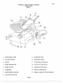
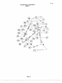
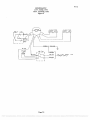
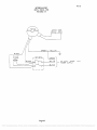
INSTRUCTION
MANUAL
Persons under age 18 are not permitted to operate or
have accessibility to operate this equipment per
U.S. Dept. of Labor Employment Standards
Administration Fact Sheet No. ESA91-3.
univex
8512/0804
ED 12
PDF compression, OCR, web optimization using a watermarked evaluation copy of CVISION PDFCompressor
TO
INSURE
SAFE
BOTH
AND
TROUBLE-FREE PERFORMANCE WE STRESS
THAT
ALL
PERSONNEL
THAT
WILL
BE
INVOLVED WITH YOUR NEW UNIVEX SLICER
MUST
READ
INSTRUCTIONS
AND
UNDERSTAND
BEFORE
THESE
ATTEMPTING
TO
OPERATE THIS UNIT.
WE APPRECIATE YOUR COOPERATION AND
YOUR BUSINESS.
SHOULD THERE BE A
QUESTION OR IF WE CAN BE OF FURTHER
ASSISTANCE,
PLEASE
CALL
US,
1403-893-6191,
PDF compression, OCR, web optimization using a watermarked evaluation copy of CVISION PDFCompressor
8512
TABLE OF CONTENTS
DESCRIPTION
PAGE
Table of Contonts
List of Illustrations
Introduction
Installation Instructions
3
3
Safy Warnings
3
Operating Instructions
Sharponing Instructions
Operator's Care of Slicer - Cleaning Instructions
Lubrication Instructions
Trouble Shooting Guide
Repair Instructions Including Disassembly, Replacemontand Reassembly
Replacemmt Parts
Warranty Information
4
4-5
s -6
7
S
9-Il
12-23
Back Cover
LIST OF ILLUSTRATIONS
ILLUSTRATIONS
Figure
Figure
Figure
1
2
3
Figure 3A
Figure 4
Figure 5
Figure 6
Figure 7
Figure 8
Figure 9
Figure 10
PAGE
Overall View of Meat Slicer
Base Assembly
Casting and Blade Assembly
Meat Deflector
Arm Assembly
Slice Control Assembly
Carriage assembly
Sharpmer Assembly
Electrical Assembly
Sthematic 115V, 60HZ, 1PH, 100V, 50/60HZ, 1PH
Sthematic 220V, 50hz, iph
2
12- 13
14 - 15
16
17
18
19
20 -21
22 - 23
24
25
Page 1
PDF compression, OCR, web optimization using a watermarked evaluation copy of CVISION PDFCompressor
OVERALL VIEW OF MEAT SLICER
8512
MODEL 8512
Figure 1
I
INDICATOR LIGHT
9 CARRIAGE ARM
2
ON-OFF SWITCH
10 ELECTRIC CORD
3
FENCE
li CARRIAGEARMKNOB
4
KNiFE SHARPENER
12
ALTFO CLUTCH LEVER
5
KNIFE GUARD
13
PROTECTIVE GUARD
6 CARRIAGE
14 GRADUATED KNOB
7 ADJUSTMENT SPACER
15
8
SERIAL NAME PLATE (ON REAR)
LAST SLICE DEVICE
Page 2
PDF compression, OCR, web optimization using a watermarked evaluation copy of CVISION PDFCompressor
INSTRUCTION MANUAL
8512
INTRODUCTION
This manual contains instructions f'or the Installation, Operation, Care, Maintenance and Repair of the
Meat Slicing Machine. Disassembly, Repair, Replacement and Reassembly Instructions are included.
Atrouble shooting guide is provided. A complete Replacement Parts List with identifying figures is
also included to facilitate identification and ordering of replacement parts.
INSTALLATION INSTRUCTIONS
INSPECTION
All Univex slicers are inspected and tested at the factoiy; however, they should be reinspected carefully
by the person makingthe installation for loose, damaged or broken parts. Detached parts and fixtures
should be checked against packing list to determine all are present. Any damages should be reported to
the canier immediately, and any shortage ofparts or fixtures reported to Univex Corporation.
Warning: After slicer has been inspected, wash slicer completely with warm water and mild soap. For
SAFETY, follow the cleaning instructions on Pages 5 & 6.
INSTALLATION
The most eflicient installation of your Univex slicer will depend upon the layout of your kitchen.
Locate your slicer where it will save steps for the operator and be sure to provide sufficient clearance
around it for ease of maintenance and cleaning, as well as for efficient and safe use.
Slicer should be operated on a sturdy bench or table with the height determined to suit the operator. It is
most important that the forearm ofthe operator be at the proper level for ease and safety of operation, as
well as for maximum production. This height is considered optimum when the carriage handle (Figure 1
[p1) ofthe slicer is at approximately the height of the operator's elbow when standing.
IMPORTANT
Warning/Caution: Electrical wiring instructions are found inthe wiring diagram (Figures 9 & IO.)
Before making electrical connections, CHECK the specifications on the nameplate
to make sure that they agree with those on your electrical service. A grounding
type three-terminal plug is provided for safety. If you do not have a mating
receptacle, have a qualified electrician provide one with grounding provisions in
accordance with local safety codes.
IMPORTANT SAFETY WARNINGS
It is a violation of United States Department of Labor regulations to permit operation ofthe slicer by
any person under the age of 18 years.
Warning: The slicer knife is extremely sharp! Never touch the knife, always keep hands and fingers
clear ofthe knife. Never run slicer without the guard or other parts in place and securely
fastened. Take extra careto avoid accidents by keeping the knife guard and sharpening
assembly cover ON at all times. When the machine is not in use, the slice adjustment knob
should be turned fully back to the closed position (beyond 'O') so that the knife edge is not
exposed.
Observe the cleaning instruction on Page 5 -6 for best results and for safety. Also remember
to always turn offthe slicer and disconnect the electrical supply cord. When slicing, always
work the carriage using only the carriage arm handle (Figure 1 [9]). Do not hold or push the
carriage from any other place.
Page 3
PDF compression, OCR, web optimization using a watermarked evaluation copy of CVISION PDFCompressor
OPERATION INSTRUCTIONS
8512
The Univex slicer is desigueci to me the cook's demand for an efliciont, sturdy slicer. The Univex
slicer will give unfinling performance over a period of years, whon operated and maintained according
to instrurtions contained herein.
START/STOP SWITCH
The slicer is started by pulling the ON/OFF switth (Figure 1 [2)) out to the ON position. A pilot light
(Figure I [1)) is provided to indicate what the slicer is turned on.
SLiCE ADJUTMENT
WarnIng: Dial-type knob adjustmrnt (Figure 1 [14)) allows for slicethicknesses ranging from paper
thin up to i 3/16". Dial graduations allow you to precisely sd up specific slice thicknesses
for various needs, Whon not in use, always raum knob back to its fully closed position
(beyond "O") so that the knife edge is not exposed.
POSITIVE HOLD CARRIAGE
Caution: A last slice gravity feed grip (Figure 1 [8)) is provided whith can be locked out of the way
whon not required, Do not use this last slice device to work the carriage back and forth. Use
only the carriage arm handle (Figure 1 [9]).
Always make sure the carriage is positively secured to the slicer by thecking to see that the
carriage arm knob (Figure I [Il]) is fully tightmed. Failure to do this could result in the
carriage striking and damagingthe knife edge.
MEAT DEFLECTOR
Be sure Meat Deflector is snapped into position towards the back ofthe blade. It should not
contact the blade, but follow the blade contour closely. If necessary adjust the location ofthe
deflector by loosoning screw (Fig 3A [4 J) and sliding the spring clip (Fig. 3A [3]) for the
correct adjustruont and tightasing the screw again.
PROTECT IVE GUARD
WARNING: The protective guard (Figure 1 [13]) covers the knife edge complctely excopt under the
sharponer cover and the forward edge where slicing will be performed. This forward
edge is covered by the edge ofthe fonce, but only whon the slice adjustmont is complctely
closed.
The knife guard (Figure 1 [5])can be removed for cleaning by unscrewingthe knife
guard knob (Figure 3 E2]). For safdy, keep the knife guard on at all times except whon
cleaning. Never operate the slicer with the knife guard removed.
SHARPENING NSTRUCTIONS
This slicer is equipped with a knife having a concave or hollowed rear surface for superior slicing
quality. Of course, any knife, howev superior, must be shaiponed regularly and properly in order to
produce not only the highest quality slices, but also to allow it to maintain its productivity. The knife
sharpener (Figure 1 [4]) on this macfiine is atop mounted built-in desigu simplicityand ease of use. It
even has an automatic aligning feature.
Page 4
PDF compression, OCR, web optimization using a watermarked evaluation copy of CVISION PDFCompressor
8512
Warning; The following sharpening procedure wilt provide high quality sharpening results and should
also be followed for safoty considerations:
L WARNING: Keep away from the knife edge.
Complotely close the slice adjustment (beyond "0") so that the knife edge is not exposed.
The knife cutting area should be clean and free from food, especially grease. Grease will
ruin the ability of a grinding stone to sharpen an edge. The stone simply will not cut. If
cleaning is necessary, follow the procedure outlined on Page 6, Remember to unplug the
electrical supply cord.
Loosen sharpener lock pin (Figure 7 [261) whith bears against sharpener post, then lift
sharpener assembly (Figure 1 [41) and rotate it 1/2 turn (1800). Then seat it down over
the knife
Tighten sharpener lock pin (Figure 7 [26]). As the lock pin is tightened, it bears on the
sharpener post and automatically aligus the grinding and deburring stones to the precise
orientations whith are presst at our factory.
Turn slicer ON. Depress the sharpener button on the back side of blade and hold in,
whith will stasi the grinding wheel rotating. Run until the beveled cutting surface cleans
up. This can take from 30 seconds to several minutes depending on how dull the blade
was allowed to become.
Release sharpener button.
Turn slicer OFF and deck for the formation of a very slight burr on the side of knife
opposite the bevel whith indicates coniple grinding ofthe bevel. This slight burr can be
dctected either visually or by picking with a small piece of stiff paper.
Turn slicer ON. Lightly press deburring (honing) button on the front side of blade and
hold for Ito 2 seconds while you turn OFF the slicer. Blade should now be complotely
sharpened and honed,
Caution: It is impoitant for best slicing results not to deburr the knife too long or the keen
edge will be destroyed dueto the formation of an undesirable second bevel on the
opposite sìde This condition tends to be the primary cause of unsatisfactory
slicing results.
Turn slicer OFF. Loosen lock pin, (Figure 7 [26 J) then lift and rdum sharpener to its
storage position. Tighten lock pin.
Clean slicer and knife according to the cleaning procedure on Page 5 -6 in order to
thoroughly remove grinding debris.
OPERATORS CARE OF SLiCER
CLEANING
Warning:
1.
Never touth the knife. Always keep your hands, fingers and arms clear of knife.
WarnIng;
2.
Turn off slicer and DISCONNECT ELECTRICAL CORD (Figure 1 [l0j) before
cleaning. Leave protective guard in place.
3.
Turn slice adjustment knob (Figure 1 [14]) to the fully closed position (beyond
"0") so that the knifè edge is not exposed.
PageS
PDF compression, OCR, web optimization using a watermarked evaluation copy of CVISION PDFCompressor
CautIon;
4.
8512
Remove carriage assembly (Figure 1 [6])whith may be washed in a sink. Use care
in washing the sharply pointed prongs on the last slice feed grip, (Figure 1 [8J).
Wash this area thoroughly. A small bristle brush is recommended. Use only warm
water and mild soap. Rinse carriage assembly with warm water and dry thoroughly
using a clean soft cloth.
Never use dotergents nor wash the slicer or any of its parts is a dishwashing mathine
or the clear protective finish will be damaged.
Warning
5.
Wash body of slicer using warm water and mild soap using a clean soft cloth.
Under no circumstances should the slicer be hose rinsed. lt is recommended that the
cloth be folded over a thin wooden stick when cleaning botween the fence plate and
the knife.
Remove knife guard (Figure 1 [5]) by loosening knife guard knob (Figure 3 [35])
and pushingthe long stud upward to lift knife guard above surface of knife. Then
carefully lift and remove guard.
Remove the meat deflector (Fig. 3A [2])by swinging away from the back of the
blade and then pushing down. As the deflector is pushed down, disengage the
bottom and then the top where it is attathed to the hub ofthe protective guard.
WARNING: 8.
CAREFULLY wash the front and rear of the knife with a cloth using warm water
and mild soap. It is recommended that the cloth be folded over a thin wooden stick
as a farther caution to avoid accidental contact with the knife. CAREFULLY wash
botween the knife edge and protective guard using a soft cloth inserted bstween
knife edge and guard on both front and rear of knife using extreme caution to never
toucfi the knife edge. Rinse with warm water applied with a cloth. Dry thoroughly
with a clean soft cloth.
CautIon:
9,
Following cleaning, a commercial non-toxic sanitizer may be wiped on the clean
surfaces with a soft clean cloth or sprayed as recommended on the container
labeling. lt is important that the sanitizer be compatible with anodized aluminum or
the clear protective finish on the slicer will be damaged. Surface should bewotted
complotely, but not to the point of running or puddling.
Warning;
IO.
Replace the knife guard. Never leave the slicer without its knife guard installed!
11.
Replace meat deflector (Fig. 3A [2 ))guidethetop connection location overthe pin,
press down and swing the bottom onto the hub, 14 it snap into place. Swing
towards the back of the blade,
Page 6
PDF compression, OCR, web optimization using a watermarked evaluation copy of CVISION PDFCompressor
8512
LUBRICATION INSTRUCTIONS
A = Clean and apply mineral
oil weekly.
C= 140 WTUSDAoìI.
B = Apply Petro-Gel (4400408) often as
required to maintain light film.
D = Lubricated for life.
Change when changing gears
Page 7
PDF compression, OCR, web optimization using a watermarked evaluation copy of CVISION PDFCompressor
8512
TROUBLESHOOTING GUIDE
TROUBLE
1. Slicer will not operate.
POSSIBLE CAUSE
REMEDY
1.1 Electrical service down.
1.1 Check electrical service.
Replace fuse or react circuit
breaker as necessary.
1.2 Burned switch contacts.
1.2 Clean or replace.
1.3 Motor capacitor defective.
1.3 Replace
1.4 Burned out motor.
1.4 Remove, test, repair or replace.
2. Motor running, blade
not turning, (carriage)
still operating).
2.1 Broken gear
2.1 Replace gear
3 Carriage not operating
(blade is operating).
3.1 Loose or broken belt
3.1 Adjust belt tension or
replace belt.
3.2 Cone clutch assembly not
engaging.
3.2 Adjust spring bushing.
3.3 Connecting rod support
jammed.
3.3 Check for foreign objects in
mechanism.
4.1 Blade contacting knife
guard.
4.1 Check for loose knife guard
knob. Shim tapered bushing.
4.2 Deflector contacting blade.
4.2 Adjust deflector.
4. Excessive noise.
4.3 Sharpener contacting blade 4.3 Adjust cover from hitting
blade.
5. Not cutting properly.
4.4 Connecting rod support
hitting bottom cover,
4.4 Pull bottom cover from
support.
4.5 Fan hitting motor cover.
4.5 Remove cover and adjust fan.
4.6 Damaged belt hitting
against motor cover.
4.6 Replace belt.
4.7 Reduction gearbox.
4.7 Replace.
5.1 Dull blade.
5.1 Sharpen blade following
outlined procedures.
5.2 Soft cheese.
5.2 Chill for best slicing results.
Page 8
PDF compression, OCR, web optimization using a watermarked evaluation copy of CVISION PDFCompressor
REPAIR INSTRUCTIONS
8512
(including disassembly, replacement and reassembly)
KNIFE (Removal) (Figure 3)
I. WARNING Disconnect electrical power cord.
Remove carriage assembly (Fig. 6).
Remove knife guard knob (Fig. 3 [35]) and carefully remove knife guard.
Loosen sharpener lock pin (Fig. 7 [26]), lift and relock in up position.
WARNING Using caution to avoid the sharp knife edge, remove the four screws (Fig. 3 [15]).
Carefully remove knife and set aside with its flat side down flush on a bench so the edge is not
exposed.
Reinstall new knife in the reverse procedures outlined above.
Even though a new knife is very sharp, the sharpening procedure specified on pages 6 and 7 should
be performed to true the new knife's bevel to the slicer.
WARNING: Worn knife should be disposed of in a safe responsible way, showing concern for others
who may handle it. It recommended that the edge ofthe knife be wrapped several times
with heavy tape and that a caution (CAUTION, SHARP EDGE) be written on both sides
ofthe knife.
KNIFE SEAL (Figure 3)
Remove knife per above instructions.
Unscrew and remove tapered bushing (Fig. 3 [12]). Maintain shims that may have been used in
assenthly.
Using a small screwdriver, carefully pry and remove the knife seal (Fig. 3 [13]) from knife support
(Fig. 3 [81).
Apply light film of mineral oil on outer diameter and lip of rubber seal.
KNIFE SUPPORT Figure
1. KNIFE SUPPORT ASSEMBLY
Remove knife per above instructions.
Loosen lama (Fig. 3 [36]) by holding tapered bushing (Fig. 3 [12]) while turning lama with
allen wrench.
Elevate left side or lama side of machine 3-1/2" to prevent oil from spilling.
Remove oil.
Page 9
PDF compression, OCR, web optimization using a watermarked evaluation copy of CVISION PDFCompressor
Remove lama by turning counter-clockwise,
8512
Push knife support assembly from bottom and remove.
2, GEAR REPLACEMENT
A. With knìfe support assembly removed, theck gear (Fig. 3 [7)) for wear. If worn, replace.
B. Remove snap ring (Fig. 3 [6)).
C. Pry gear off of shaft.
D. Replace gear in reverse procedures.
3. BEARING REPLACEMENT
Remove tapered bushing (Fig. 3 [12)).
Press shaft (Fig. 3 [5)) from top of blade support assembly.
C, Remove shim washers (7120040) if presont.
D. Using a small screwdriver, carefully pry and remove the knife seal (Fig. 3 [13)).
E. Reznoverainingring(Fig. 3 [lfl).
F. Invt assembly on bmd and drive bearings and spacer from back side.
G. Put new bearing in by reversing above procedure.
MOTOR REPLACEMENT/OR BELT REPLACEMENT
Follow procedure for removing blade support assembly.
Remove acorn nuts (Fig. 2 [47)).
Remove motor cover (Fig. 2 [45)).
Looson and pull fan (Fig. 2 [48)).
Pivot idler arm (Fig. 2 [43])to ease tmsion on belt.
Remove belt (Fig. 2 [50)).
a. If only replacing belt, put on new belt at this point and reassemble in reverse procedure.
For motor replacemont, continue disassembly by removing pulley (Fig. 2 [49)).
Removetworemainingnuts(Fig. 8 [5).
Pull motor (Fig. 8 [1)) from housing.
Connect all wiring to new motor following wiring diagram on page 24 or 25.
Reverse above procedures to complcte installation of new motor.
Page 10
PDF compression, OCR, web optimization using a watermarked evaluation copy of CVISION PDFCompressor
ELECTRICAL ASSEMBLY
8512
I. WARNING DISCONNECT ELECTRICAL SUPPLY
Remove four rubber feet (Fig. 2 [241) and 4 extonsion legs (Fig. 2 [52 J).
Remove bottom cover (Fig. 2 [19)).
Remove casing cover (fig. 8 [22)).
Distharge capacitors by jumping across terminals with electrically protected screwdriver.
Remove reduction gear rod (Fig. 2 [34)) by removing two bolts (Fig. 2 [38)) and removing set
screw at reduction gear md.
Remove switth shaft (Fig. 8 [16)) by loosming nut (Fig. 8 [iS)) near switth md.
Remove capacitor on left to access ground screw holding electrical equipmmt casing.
Remove electrical equipmmt casing by removing three screws (Fig. 8 [21)).
Replace capacitors (Fig. 8 [24)) if found to be defective.
il. Relay (Fig. 8 [7)) and switth (Fig. 8 [20)) can also be thecked from this procedure.
12. Replace any defective electrical componont and reverse procedures to reassemble.
Page 11
PDF compression, OCR, web optimization using a watermarked evaluation copy of CVISION PDFCompressor
8512
BASE ASSEMBLY
Figure 2
ILLUS.NO. PART NO,
1.
2.
3.
4.
5.
6.
7.
8.
9.
10.
11.
12.
13.
14.
15.
16.
17.
18.
19.
20.
21.
22.
23.
24.
25.
26.
27.
28.
29.
30.
31.
32.
33.
34.
35.
36.
37.
38.
39.
40.
41.
42.
43.
44.
45.
46.
47.
48.
8512300A
6509098
8512823
8512826
8512827
8512828
8512824
8512829
8512818
8512819
6509028
6509040
8512817
1012167
8512814'
8512812
8512811
8512813
8512853
8512816
8512805
8512808
8512855
8512803A
8512516
8512803
6509143
DESCRIPTION
SUPPORT, CARRIAGE, ALSO FIG.4 [6)
SET SCREW, M6-I.0 X 8MM
BOLT, CONE CLUTCH
BUSHING, SPRING
SET SCREW, M5-0.8 X 5MM
SPRING
QTY.
1
4
2
I
CAM
1
KNOB, CONE CLUTCH
BUSHING, AUTOMATIC
ROD, ROUNDGUIDE
WASHER,M8
SCREW, SOC HD CAP M8-1.25 X 25MM
SCREW, CRANK ATTACHMENT
BALL BEARING
SCREW, CRANK ATTACHMENT
BALLBEARING
CRANK
SPACER
COVER, BOTTOM
SPACER
RESERVED
SUPPORT, CONNECTION ROD
KEY
FOOT
1
2
2
1
1
1
1
1
I
1
1
4
GEAR, REDUCTION
RESERVED
WASHER, M6
STUD
1
4
4
4
NUT M61.0
RESERVED
8512846
8512862
8512831
8512830
8512836
8512834
8512832
8512833
6509131
1204044
8512863
1204045
8512864
8512870
8512201
8512851
8512868
KEY
4
PULLEY, MOTOR
KEY, REDUCTION GEAR
ROD, REDUCTION GEAR
1
1
1
KEY
1
BALLBEARING
FLANGE, BEARING
SCREW,M6-1.OX20MJvI
2
2
NUT,JAMM8-l.25
2-
SCREW M8-1.25 X 50MM
BEARING, IDLER
SCREW, M6-1.OX2OMM
ARM, IDLER
AXLE, IDLER BEARING
COVER, MOTOR
1
1
2
1
STUD/SCREWM6-1.o
2
RESERVED
FAN
1
Page 12
PDF compression, OCR, web optimization using a watermarked evaluation copy of CVISION PDFCompressor
BASE ASSEMBLY
Figure 2 (CONT.)
ILLUS.NO. PARTNO.
49.
50.
51.
52
53
54
55
8512865
8512867
8512637
8512248
8512866
8512869
8512871
DESCRIPTION
8512
QTY.
PULLEY
VBELT
VENT, PLASTIC
LEG, EXTENSION
SPRING, EXTENSION
POST, SPRING
PIN
4
Page 13
PDF compression, OCR, web optimization using a watermarked evaluation copy of CVISION PDFCompressor
8512
CASTING and BLADE ASSEMBLY
Figure 3
ILLUS.NO. PART NO.
8512736
8512203
8512215
8512216
8512729
8512218
8512220
8512730
8512731
1030019
8512225
8512226
8512227
Il.
86 12009*
8512229
8512228
is:
8512234
8512861
8512237
6509080
6509081
8512214
7510084
8512209
8512208
34,
35..
38
39
40
41
42
43
44
45
46
7510067
8512233
8512232
8612011
8512928
8512930
8512929
8512030
6509082
4400339
7510012
8512735
8512871
DESCRIPTION
CASTING
PIN
SEAL
SEAL, O-RING
ROD, CUTTER SUPPORT
RETAINING RING
GEAR
SUPPORT, BLADE, INCLUDES 4 THRU 13
SPACER, BEARING
BEARING
RETAINING RING
BUSHING, TAPERED
SEAL
GUARD, KNIFE
SCREW, FLAT HD M5-0.8 X 12MM
BLADE
RESERVED
RESERVED
FENCE
SUPPORT. FENCE
SET SCREW
STUD, FENCE ADJUSTING
ACORN NUT, M8
RESERVED
SET SCREW, M6-1.0 X I6MMB
KNOB, GRADUATED
RESERVED
RESERVED
Rl VET
QTY.
2
2
3
2
2
2
2
GRADUATED KNOB BUSH
RESERVED
RESERVED
RESERVED
SCREW, SOC HD CAP M6-1.0 X 20MM
KNOB, KNIFE GUARD
LAMA
ROD, KNIFE GUARD
RIGHT SUPPORT
SCREW M8-l.0 X 45MM
LEFT SUPPORT
PROTECTIVE GUARD (SEE FIG. 3A)
WASHER
LABEL. MAX (NOT SHOWN)
SPACER, .81 ID X 1.18 OD X . I2THK
SCREW, SOC HD M5-0.8 X 25MM
PIN
4
4
4
* ILLUS NO. 14 INCLUDES ILLUS NO.46
Page 14
PDF compression, OCR, web optimization using a watermarked evaluation copy of CVISION PDFCompressor
CASTING and BLADE ASSEMBLY
8512
Figure 3
Page 15
PDF compression, OCR, web optimization using a watermarked evaluation copy of CVISION PDFCompressor
MEAT DEFLECTOR
8512
Figure 3A
ILLUSNO. PART NO.
1.
2
3
4
5
6
7
8
8512030
7512156
7510342
7510346
7510343
7510344
7510345
7510347
DESCRIPTION
PROTECTIVE GUARD
DEFLECTOR
CLIP. SPRING
SCREW PAN HD MS X 10MM
POST
SPRING
PLUNGER
POST, HEADED
QTY.
I
1
1
I
I
1
Page 16
PDF compression, OCR, web optimization using a watermarked evaluation copy of CVISION PDFCompressor
ARM ASSEMBLY
Figure 4
ILLUS.NO. PART NO.
2.
3.
4.
5*
6.
7.
8.
9.
lo.
11.
12.
13.
14.
15.
16.
17.
18.
19.
20.
21.
7510038
8512314
8512313
8512312
8512301
8512300
8512316
8512318
8512317
9512299
1053510
8512308
6509031
6509028
6509042
8512319
6509044
6509045
6509046
8512325
8512326
DESCRIPTION
RUBBER SHOCK ABSORBER
SPRING, DAMPER
SCREW, SOC HD CAP M8-1.25 X 30MM
ROD, ROUND GUIDE
BUSHING
8512
QTY.
2
2
2
ARM SU000RT
BAR, FRAME
WASHER, EXTERNAL TOOTH
SCREW
BUSHING, ECCENTRIC
SCREW, CAP M6-1.0 X 25MM HEX HD
BOLT, BEARING LOCKING
BEARING
WASHER, M8
STUD, ARM ATTACHMENT
CARRIAGE ARM
KNOB, CARRIAGE ARM
HANDLE, CARRIAGE ARM
SCREW, HEX HD WASHER M6-1.OX15MM
CARRIAGE ANCHOR
STUD, CARRIAGE ANCHOR
2
2
2
2
* 8512301 PART OF ILLUS NO.6, CANNOT BE PURCHASED
Page 17
PDF compression, OCR, web optimization using a watermarked evaluation copy of CVISION PDFCompressor
8512
SLICE CONTROL ASSEMBLY
Figure 5
ILLUS.NO. PART NO.
1.
2.
3.
4.
5.
6.
7.
8.
9.
10.
11.
12.
13.
14.
15.
16.
17.
18.
19.
20.
21.
22.
23.
24.
25.
26.
27.
28.
29.
30.
*
7510067
8512527
8512526
8512525
7510065
7512076
8512839
6509028
6509071
8512511
8512512
7510073
8512326
6509131
7510061
8512518
6509046
* 8512501
8512502
8512503
8512504
8512510
6509086
8512507
8512506
8512508
8512505
8512529
8512530
8512500
DESCRIPTION
BOLT, SOC HD CAP M6-1.0 X 20MM
BOLT, HEX HD M8-1,25 X 30MM
JIB
WASHER, EXTERNAL TOOTH M6
SCREW, HEX HD M6-1.0 X 20MM
SUPPORT, TAPER
NUT, M8-1.25
WASHER, M8
STUD, CRANK
BLOCK, SLICE CONTROL MOVING
SHAFT, SLICE CONTROL
STUD, JIB ATTACHMENT
SETSCREW, M8-1 25 X 20MM
NUT, THIN M8-l.25
SPRING
SCREW, HEX HD M6-1.0 X 10MM
WASHER. M6
ECCENTRIC PIN
GEAR
WASHER, SPECIAL
BOLT, HEX HD ME-1.25 X 5OMMT
SHAFT, GRADUATED KNOB
FLEXIBLE WASHER
WORM GEAR
QTY.
2
2
2
2
2
BALL
ROLL PIN
BALL STUD
SCREW, PAN HD M5-0.8 X 25MM
NUT, M5-0,8
SLICE CONTROL GUIDE UNIT
Illus 18 (8512501) can not be purchased separately; included in IlIus 19(8512502)
Page 18
PDF compression, OCR, web optimization using a watermarked evaluation copy of CVISION PDFCompressor
8512
CARRIAGE ASSEMBLY
Figure 6
ILLUS NO. PART NO,
2
3
4
5
6
7
8
9
10"
11
12
13
14
15
16
17
18
19
20
8512432
8512437
8512448
8512433
8512925
8512924
8512926
6509153
8512428
8512427
8512425
8512438
8512434
RESERVED
8512431
8512927
6509038
6509058
6509059
8512439
DESCRIPTION
QTY.
SPACER, ADJUSTMENT
STUD & KNOB, ADJUSTMENT SPACER
STUD
BUSHING, ADJUSTMENT SPACER
SUPPORT, LAST SLICE DEVICE
HANDLE, LAST SLICE DEViCE
LAST SLICE DEVICE
KNOB, LAST SLICE DEVICE SHAFT
SHAFT, LAST SLICE DEVICE
BUSHING, LAST SLICE DEVICE
CARRIAGE
NYLON PIP, ADJUSTMENT SPACER
SHAFT, ADJUSTMENT SPACER
I
NYLON PIP, LAST SLICE DEVICE
STUD, LAST SLICE DEVICE
SCREW, FLAT HEAD
S
1
I
3
1
1
1
BOXNUT,M10-1.5
WASHER, SPECIAL
STUD, CARRIAGE
I
1
* = PART OF ILLUS i (8512432), CANNOT BE PURCHASED SEPARATELY.
** = PART OF ILLUS 5(8512925), CANNOT BE PURCHASED SEPARATELY.
Page 19
PDF compression, OCR, web optimization using a watermarked evaluation copy of CVISION PDFCompressor
8512
SHARPENER ASSEMBLY
Figure 7
ILLUS NO. PART NO.
1
2
3
4
5
6
7
8
9
10
11
12
13
14
15
16
17
18
19
20
21
22
23
24
25
26
27
7510151
6509153
6509151
6509150
6509149
6509125
6509137
6509138
7510120
8512728
6509147
6509127
6509128
6509129
6509130
6509131
6509134
6509133
6509135
6509136
6509132
6509143
6509144
6509142
6509141
6509128
6509 126A
7510150
DESCRIPTION
SHARPENER ASSEMBLY WITH COVER
KNOB, COVER
COVER, SHARPENER
NUT, COVER SPACER
SPACER. COVER
WASHER, SETPIN
SCREW
WASHER
SETPIN, SHARPENER
PIN, SHARPENER CASTING
BOLT, SHARPENERGIJIDE
SPRING
BUSHING
STUD, HONING STONE
STONE, HONING
NUT
SPRING
BALL
BUTTON, DEPRESS
SET SCREW, DEPRESS BUTTON
WASHER, HORNiNG STONE
NUT, SHARPENINGSTONE
WASHER, SHARPENJNG STONE
STONE, SHARPENING
STUD, SHARPENING STONE
BUSHING
MOUNT, SHARPENER STONE
LOCKING PIN, SHARPENER
QTY.
I
1
1
1
2
2
1
1
2
2
2
2
1
1
1
1
Page 20
PDF compression, OCR, web optimization using a watermarked evaluation copy of CVISION PDFCompressor
8512
SHARPENER ASSEMBLY
Figure 7
PART OF ILLUS
IN FIG. 3
41\
Page 21
PDF compression, OCR, web optimization using a watermarked evaluation copy of CVISION PDFCompressor
8512
ELECTRICAL ASSEMBLY
115v,60hz iph
220v, 50hz, iph
Figure 8
ILLUS.NO.
1.
2.
3.
4.
5.
6.
7.
8.
9.
10.
11.
12.
13.
14,
15.
16.
17.
18.
19.
20.
21.
22.
23.
24.
25.
26.
27.
28
29
PART NO.
DESCRiPTION
8512844
8512844A
8512601
8512602
8512932
8512934
MOTOR, 115V, 60Hz, 1PH, 1/2HP, 100V,50/60HZ, IPH
MOTOR, 220V, 50HZ, 1PH, 1/2HP
8512620
8512622
8512621
8512606
1814069
1814069A
8512624
8512627
8512615
8512614
8512613
4400053
4400053A
8512612
8512611
7120009
8512609
8512626
8512608
8512616
8512618
6509028
8512617
8512643
8512935
8512933
RELAY, 11SVONLY
NUT, M4-0.7
SCREW, PAN HD M4-0.7 X 10MM
BOLT, MOTOR SHORT
LAMP, WARNING, 1 1SV/100V
LAMP, WARNING, 220V
FASTENER, CABLE
SCREW, PHIL HD SHEET METAL
KNOB, SWITCH
NUT, M6-1.0
SHAFT, SWITCH
CORDANDPLUG,115V/100V
CORD AND PLUG, 220V
JOINT
NUT
SWITCH
SCREW,M5-0.8X12MM
COVER, CASING
ELECTRICAL EQUIPMENT CASING
CAPACITOR, 3OMFD, 450V,(115V/100V)
CAPACITOR, 1OMFD, 500V,(220V)
WASHER, MS
NUT, M8-1.25
WASHER
BUSHING/NUT
SPRING
KEY
RUBBER SHOCK ABSORBER
WORM GEAR
SPACER
RESERVED
QTY.
I
1
1
1
1
4
1
1
I
3
2
1
1
1
i
3
1
1
2
1
2
6
Page 22
PDF compression, OCR, web optimization using a watermarked evaluation copy of CVISION PDFCompressor
8512
ELECTRICAL ASSEMBLY
Figure 8
Page 23
PDF compression, OCR, web optimization using a watermarked evaluation copy of CVISION PDFCompressor
8512
SCHEMATIC
115V, 60HZ, 1PH
100V. 50/60HZ, IPH
Figure 9
CAPAC TOR
RELAY
II
OREEN / YELLOW
BLACK
PILOT
LIGHT
CAPAC I TOR
3OMO. 450V
ISV
SWITCH
3OMFO. 450V
o
o
I)
o
I
GREEN
WH I TE
TO 115V. 50HZ. IPH
POWER SUPPLY
BLACK
Page 24
PDF compression, OCR, web optimization using a watermarked evaluation copy of CVISION PDFCompressor
8512
SCHEMATIC
220V, 50HZ, 1PH
FIGURE 10
CARAO TOR
IOMFD, 500V
o
GREEN / YELLOW
BLACK
P LOT
L GHT
SWITCH
I
ORE EN
WHITE
BLACK
o
H
BLACK
-
TO 220V. 50HZ.
PH
POWER SUPPLY
Page 25
PDF compression, OCR, web optimization using a watermarked evaluation copy of CVISION PDFCompressor