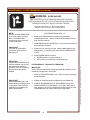
1
361
WELLS MANUFACTURING
10 Sunnen Dr., St. Louis, MO 63143
telephone: 314-678-6314
fax: 314-781-2714
www.wellsbloomfield.com
OWNERS MANUAL
ELECTRIC
OPEN-FRYPOT
30# FRYER
with AUTO-LIFT
MODELS
WFAE-30F
with or without
Optional Filter Wand
WVAE-30F
(FRYER SECTION ONLY)
with or without
Optional Filter Wand
Includes
WFAE-30F
INSTALLATION
USE & CARE
EXPLODED VIEW
PARTS LIST
WIRING DIAGRAM
WARNING:
Improper installation, adjustment, alteration, service or maintenance can
cause property damage, injury or death. Read the installation and operating
instructions thoroughly before installing, using or servicing this equipment.
IMPORTANT: DO NOT DISCARD THIS MANUAL
This manual is considered to be part of the appliance and is to be given to the OWNER or
MANAGER of the restaurant, or to the person responsible for TRAINING OPERATORS of
this appliance. Additional manuals are available from your WELLS DEALER.
THIS MANUAL MUST BE READ AND UNDERSTOOD BY ALL PERSONS USING OR
INSTALLING THIS APPLIANCE. Contact your WELLS DEALER if you have any
questions concerning installation, operation or maintenance of this equipment.
p/n 2M-301669 Rev. E
M361
120227
LIMITED WARRANTY STATEMENT
Unless otherwise specified, all commercial cooking
equipment manufactured by WELLS MANUFACTURING is
warranted against defects in materials and workmanship for
a period of one year from the date of original installation or
18 months from the date of shipment from our factory,
whichever comes first, and is for the benefit of the original
purchaser only.
THIS WARRANTY IS THE COMPLETE AND ONLY
WARRANTY, EXPRESSED OR IMPLIED IN LAW OR IN
FACT, INCLUDING BUT NOT LIMITED TO, WARRANTIES
OF MERCHANTABILITY OR FITNESS FOR ANY
PARTICULAR PURPOSE, AND/OR FOR DIRECT,
INDIRECT OR CONSEQUENTIAL DAMAGES IN
CONNECTION WITH WELLS BLOOMFIELD PRODUCTS.
This warranty is void if it is determined that, upon inspection
by an authorized service agency, the equipment has been
modified, misused, misapplied, improperly installed, or
damaged in transit or by fire, flood or act of God. It also
does not apply if the serial nameplate has been removed, or
if service is performed by unauthorized personnel. The prices charged by Wells Manufacturing for its products are
based upon the limitations in this warranty. Seller’s
obligation under this warranty is limited to the repair of
defects without charge by a Wells Manufacturing factory
authorized service agency or one of its sub-service
agencies. This service will be provided on customer’s
premises for non-portable models. Portable models (a
device with a cord and plug) must be taken or shipped to
the closest authorized service agency, transportation charges prepaid, for service. In addition to restrictions contained in this warranty, specific limitations are shown in the
Service Policy and Procedure Guide. Wells Manufacturing
authorized service agencies are located in principal cities.
This warranty is valid in the United States and Canada and
void elsewhere. Please consult your classified telephone
directory, your foodservice equipment dealer or contact:
Wells Manufacturing
10 Sunnen Dr., St. Louis MO 63143 USA
phone (314) 678-6314 or fax (314) 781-2714
for information and other details concerning warranty.
SERVICE POLICY AND PROCEDURE GUIDE and ADDITIONAL WARRANTY EXCLUSIONS
1.
2.
3.
5.
6.
cleaning schedules, are customer responsibility. Those
miscellaneous adjustments noted are customer
responsibility. Proper attention to preventative
maintenance and scheduled maintenance procedures
will prolong the life of the appliance.
7. Travel mileage is limited to sixty (60) miles from an
Authorized Service Agency or one of its sub-service
agencies.
8. All labor shall be performed during regular working
hours. Overtime premium will be charged to the buyer.
9. All genuine Wells replacement parts are warranted for
ninety (90) days from date of purchase on nonwarranty equipment. This parts warranty is limited only
to replacement of the defective part(s). Any use of
non-genuine Wells parts completely voids any
warranty.
10. Installation, labor, and job check-outs are not
considered warranty and are thus not covered by this
warranty.
11. Charges incurred by delays, waiting time or operating
restrictions that hinder the service technician’s ability to
perform service are not covered by warranty. This
includes institutional and correctional facilities.
SHIPPING DAMAGE CLAIM PROCEDURE
NOTE: For your protection, please note that equipment in
this shipment was carefully inspected and packaged by
skilled personnel before leaving the factory. Upon
acceptance of this shipment, the transportation company
assumes full responsibility for its safe delivery.
IF SHIPMENT ARRIVES DAMAGED:
1. VISIBLE LOSS OR DAMAGE: Be certain that any
visible loss or damage is noted on the freight bill or
express receipt, and that the note of loss or damage is
signed by the delivery person.
2. FILE CLAIM FOR DAMAGE IMMEDIATELY:
Regardless of the extent of the damage.
3.
CONCEALED LOSS OR DAMAGE: if damage is
unnoticed until the merchandise is unpacked, notify the
transportation company or carrier immediately, and file
“CONCEALED DAMAGE” claim with them. This
should be done within fifteen (15) days from the date
the delivery was made to you. Be sure to retain the
container for inspection.
Wells Manufacturing cannot assume liability for damage or
loss incurred in transit. We will, however, at your request,
supply you with the necessary documents to support your
claim.
xi
361 2M-301669 Owners Manual WFAE-30F Free-Standing 30# Electric Fryer
4.
Resetting of safety thermostats, circuit breakers, over
load protectors, and/or fuse replacements are not
covered by this warranty unless warranted conditions
are the cause.
All problems due to operation at voltages or phase
other than specified on equipment nameplates are
not covered by this warranty.
Conversion to correct voltage and/or phase must be
the customer’s responsibility.
All problems due to electrical connections not made
in accordance with electrical code requirements
and wiring diagrams supplied with the equipment are
not covered by this warranty.
Replacement of items subject to normal wear, to
include such items as knobs, light bulbs; and, normal
maintenance functions including adjustments of
thermostats, adjustment of micro switches and
replacement of fuses and indicating lights are not
covered by warranty.
Damage to electrical cords and/or plug due to exposure
to excessive heat are not covered by this warranty.
Full use, care, and maintenance instructions supplied
with each machine. Noted maintenance and
preventative maintenance items, such as servicing and
TABLE OF CONTENTS
WARRANTY
SPECIFICATIONS
FEATURES & OPERATING CONTROLS
OPTIONAL FILTER WAND
PRECAUTIONS & GENERAL INFORMATION
AGENCY LISTING INFORMATION
INSTALLATION
PREPARATION PRIOR TO OPERATION
OPERATION
MAINTENANCE INSTRUCTIONS
FILTER OPERATION
DISCARDING USED OIL
OPTIONAL FILTER WAND
CLEANING
TROUBLESHOOTING SUGGESTIONS
EXPLODED VIEW & PARTS LIST
WIRING DIAGRAM
PARTS & SERVICE
CUSTOMER SERVICE DATA
xi
1
2
3
5
5
6
8
11
12
15
17
18
20
21
24
25
25
INTRODUCTION
Thank You for purchasing this Wells Manufacturing appliance.
Proper installation, professional operation and consistent maintenance of this appliance will ensure that
it gives you the very best performance and a long, economical service life.
This manual contains the information needed to properly install this appliance, and to use and care for
the appliance in a manner which will ensure its optimum performance.
361 2M-301669 Owners Manual WFAE-30F Free-Standing 30# Electric Fryer
SPECIFICATIONS
DIMENSIONS
CAPACITIES
Wide
Deep
High
15.62”
33.25”
40.0”
Lbs.
Kg.
Cooking Oil
(Liquid Shortening Only)
30
14
Chicken (Fresh)
14
6
Chicken (Frozen)
12
5
ELECTRICAL SPECIFICATIONS
DOMESTIC
VOLTAGE
REQUIREMENTS
208 VAC
EXPORT (EU)
240VAC
380-415V
3NAC
NOTE: Shipped from factory 3Ø, field convertible to 1Ø
POWER
CONSUMPTION
9,000 watts
9,000 watts
9.300 watts
AMPERAGE
43.3 amps (1 ø)
25.0 amps per leg (3ø)
37.5 amps (1 ø)
21.7 amps per leg (3ø)
L1 = 14,3 amps
L2 = 13,0 amps
L3 = 13,0 amps
N = 2,7 amps
1
FEATURES & OPERATING CONTROLS
BACK VIEW
UPPER CONTROL PANEL
16
WELLS
5
6
1
B
U
Z
Z
E
R
7
2
FRYER
3
4
OFF
FILTER
14
COOK
HEAT
POWER
LOWER CONTROL PANEL
THERMOSTAT
FILTER
325
300
ON
350
HI-LIMIT
RESET
8
OFF
CAUTION
FRYER MUST BE OFF
BEFORE USING FILTER
250
375
275
ºF
9
10
Fig. 1 WFAE-30F Features & Operating Controls
FRYER position energizes the FRYER and POWER LIGHT;
de-energizes FILTER PUMP. HEATING ELEMENTS energized
and regulate to setting on CONTROL THERMOSTAT (8).
POWER SWITCH
(FRYER-OFF-FILTER)
OFF position de-energized FRYER and FILTER PUMP.
FILTER position de-energizes FRYER; energizes FILTER PUMP
SWITCH (6).
2
POWER LIGHT (amber)
Glows to indicate FRYER is energized.
3
HEAT LIGHT (amber)
Glows to indicate HEATING ELEMENT energized;
Off when oil temperature reaches setting on CONTROL
THERMOSTAT (8).
4
COOK LIGHT (amber)
Glows to indicate COOK LEVER in cook position.
5
TIMER
Controls LIFT CRADLE AND BUZZER. Start TIMER by pressing
red button at center of knob. Lift CRADLE will lower. Pointer
indicates time remaining. When time reaches “0” BUZZER
sounds and LIFT CRADLE raises.
6
BUZZER LIGHT (amber)
7
BUZZER SWITCH
When lit, indicates BUZZER SWITCH (item 7) is turned ON and
BUZZER CIRCUIT is active
Activates BUZZER CIRCUIT. When ON will sound BUZZER anytime TIMER is at “0”. Turn switch OFF or activate timer to silence buzzer.
2
361 2M-301669 Owners Manual WFAE-30F Free-Standing 30# Electric Fryer
1
FEATURES & OPERATING CONTROLS (continued)
WARNING
WARNING:
FIRE HAZARD / HOT OIL
The HI-LIMIT THERMOSTAT is a FIRE PROTECTION DEVICE.
If tripping persists, clean debris from the space between the
hi-limit bulb and the element to enhance oil flow and facilitate reset.
Otherwise, contact your authorized Wells Service Agent for repairs.
DO NOT ATTEMPT TO BYPASS OR HOLD IN THE BUTTON OF
THE HI-LIMIT THERMOSTAT. A SERIOUS FIRE MAY RESULT.
ON position energizes FILTER PUMP and causes oil in
RESERVOIR (10) to be pumped back into frypot.
8
FILTER PUMP SWITCH
(ON-OFF)
OFF position de-energizes FILTER PUMP.
NOTE: POWER SWITCH (1) must be in FILTER position for
FILTER PUMP to operate.
HI-LIMIT THERMOSTAT
Provides over-temperature protection by de-energizing HEATING
ELEMENTS should oil temperature exceed factory pre-set limits.
10 TEMPERATURE CONTROL
THERMOSTAT
Controls oil temperature. Range: 250ºF (121ºC)
375ºF (191ºC)
11 DRAIN VALVE LEVER
Opens and closes the DRAIN VALVE:
Turn counterclockwise (vertical) to OPEN
Turn clockwise (horizontal) to CLOSE
12 POWER OUTLET BOX
Electrical service connection TERMINAL BLOCK located here.
13 OIL FILTER RESERVOIR
Collects oil from FRYPOT for filtering or disposal.
Holds filter screen, filter paper & filter paper holder.
FILTER PUMP MOTOR
14 RESET BUTTON
(located at rear of motor)
FILTER PUMP MOTOR is equipped with an overheating
protection device.
RESET must be performed manually. Allow motor to cool for
approx. 30 min, then firmly press the red button.
15 FRY BASKET
Holds product to be cooked.
16 BASKET HANDLE
Used to manually raise and lower FRY BASKET into and out of
FRYPOT.
REMOVE FROM BASKET BEFORE ACTIVATING TIMER!
17 DRIP PAN
Collects liquids that accumulate on top of fryer.
NOT SHOWN
361 2M-301669 Owners Manual WFAE-30F Free-Standing 30# Electric Fryer
9
LIFT CRADLE
(see page 8)
Lowers fry basket into frypot during cook cycle. Automatically
raises from frypot at end of cook cycle
FRYPOT COVER
(see front cover)
Hinged cover. When tilted forward, rises and lowers with cradle
lift. When tilted back, remains open during cook cycle
(OPTIONAL) FILTER WAND
Wash sides of frypot, or transfer oil to disposal container.
See page 4.
3
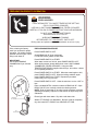
FEATURES & OPERATING CONTROLS (continued)
OPTIONAL FILTER WAND
FILTER
PUMP
QUICK DISCONNECT
FEMALE FITTING
LOCKING RING
OT
DRAIN VALVE
TO
YP
FR
SAFETY SWITCH
DRAIN HANDLE
3-WAY VALVE HANDLE
QUICK DISCONNECT
MALE FITTING
INSULATED HANDLE
WAND ASSEMBLY
4
361 2M-301669 Owners Manual WFAE-30F Free-Standing 30# Electric Fryer
NOTE: Wand option must be ordered at time of initial build.
PRECAUTIONS AND GENERAL INFORMATION
This fryer is intended for use in commercial establishments only.
This appliance is intended to prepare food for human consumption.
No other use is recommended or authorized by the manufacturer or its
agents.
DO NOT open any panel that requires the use of tools for access. Live
electric circuits may be exposed by opening such panels. Opening
access panels must be performed by an Authorized Service Agent only. Any procedure that requires the use of tools must be performed by
a qualified technician.
This appliance is equipped with an oil filtration system designed to filter
hot liquid shortening only. Water, cleaning agents and/or other liquids
will contaminate the oil and may damage the filter pump.
Operators of this appliance must be familiar with the appliance use,
limitations and associated restrictions. Operating instructions must be
read and understood by all persons using or installing this appliance.
Cleanliness of this appliance is essential to good sanitation. Read and
follow all included cleaning instructions and schedules to ensure the
safety of the food product.
DO NOT submerge any part of this appliance in water unless
specifically instructed to do so. This appliance is not jet stream
approved. DO NOT direct water jet or steam jet at this appliance,
nor at any control. DO NOT splash or pour water on, in or over any
controls. DO NOT wash area around this appliance with water jet.
Any part which has become wet must be thoroughly dried before use.
361 2M-301669 Owners Manual WFAE-30F Free-Standing 30# Electric Fryer
Cooking oil will be very hot when in use. Contact will cause severe
injury, and can cause blindness or death. Wear appropriate heatprotective clothing when operating or servicing this appliance.
This appliance must be operated with the supplied legs and casters
properly installed.
The technical content of this manual, including any parts breakdown
illustrations and/or adjustment procedures, is intended for use by qualified technical personnel only.
This manual is considered to be a permanent part of the appliance.
This manual and all supplied instructions, diagrams, schematics, parts
breakdown illustrations, notices and labels must remain with the
appliance if it is sold or moved to another location.
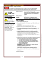
DANGER:
BURN HAZARD
Cooking oil in this appliance
operates at very high
temperatures. Contact with
hot oil can cause severe
injury or death. Wear
appropriate heat-protective
clothing when operating or
servicing this appliance.
WARNING:
BURN HAZARD
DO NOT allow water or ice to
contact hot oil. DO NOT
attempt to cool the oil with
water or ice. The water will
boil violently. Contact with
splattering or foaming hot oil
will cause severe burns.
WARNING:
SLIP AND FALL
HAZARD
Spilled cooking oil is very
slippery and can cause falls.
Clean up oil spills promptly.
CAUTION:
BURN HAZARD
Exposed surfaces can be hot
to the touch and may cause
burns.
CAUTION:
HEALTH HAZARD
Old cooking oil can be a
breeding ground for bacteria.
Clean and sanitize exterior
surfaces of fryer regularly.
AGENCY LISTING INFORMATION
This appliance conforms to NSF Standard 4 for sanitation only if
installed in accordance with the supplied Installation Instructions and
maintained according to the instructions in this manual.
STD 4
E6070
Domestic fryers are
and 240V.
and
listed under UL File E6070 for 208V
Export (European) fryers comply with
US
standards
for 380-415V 3NAC.
5
INSTALLATION
NOTE: DO NOT discard
the carton or other packing
materials until you have
inspected the appliance for
hidden damage and tested it
for proper operation.
Refer to SHIPPING DAMAGE
CLAIM PROCEDURE on the
inside front cover of this
manual.
WARNING:
FIRE HAZARD
Do not store gasoline or
any other flammable or
combustible material near this
appliance.
The area where the fryer is
installed must be kept clear of
combustibles and flammables.
This includes mops, rags,
grease, wrapping paper and
electric cords.
Installation and startup must
be performed by a Wells Manufacturing Authorized Service
Agency.
UNPACKING & INSPECTION
Carefully remove the appliance from the carton. Remove all
protective plastic film, packing materials and accessories from the
appliance before connecting performing any installation procedure.
Carefully read all instructions in this manual and the Installation
Instruction Sheet packed with the appliance before starting any
installation.
Read and understand all labels and diagrams attached to the
appliance.
Carefully account for all components and accessories before
discarding packing materials. Store all accessories in a convenient
place for later use.
COMPONENTS
1 ea.
FILTER RESERVOIR
1 ea.
FILTER SCREEN
1 ea.
FILTER PAPER HOLDER
4 ea.
OIL FILTER SUCTION TUBE O-RINGS
1 ea.
LIFT CRADLE
1 ea.
FRY BASKET
1 ea.
BASKET LIFTING HANDLE
1 ea.
WAND ASSEMBLY (if optioned)
ACCESSORIES
1 ea.
LITERATURE PACKAGE
1 pk.
FILTER PAPER
1 pk.
FILTER POWDER
1 ea.
HIGH TEMPERATURE BRUSHES
1 ea.
CLEANOUT DOWEL (wood rod)
SETUP
Installer must complete the
WARRANTY REGISTRATION
and FRYER CHECKOUT
form, and record the details of
the particular installation on
the CUSTOMER SERVICE
DATA form in this manual.
It is the responsibility of the installer to verify that this fryer installation is
in compliance with local code authorities and with the specifications
listed in this manual.
Certain local or state codes require fryers to be restrained with a tether
or other approved restraint device. It is the responsibility of the installer
to check with the authority having jurisdiction, in order to ascertain the
applicability of this requirement to this specific fryer installation.
Setup the fryer only on a firm, level, non-combustible surface. Verify
local codes for requirements. Concrete, tile, terrazzo or metal surfaces
are recommended. Metal or tile over combustible material may not
meet code for non-combustible surfaces.
Verify that the unit sits firmly ON BOTH CASTERS AND BOTH LEGS.
With the adjustable legs, adjust as required to level the appliance.
Both legs and both casters must be adjusted to firmly contact the floor
in order to prevent tipping.
Refer to the Installation Instruction Sheet for required clearances.
Maintain required clearances between the appliance and adjacent
combustible surfaces.
6
361 2M-301669 Owners Manual WFAE-30F Free-Standing 30# Electric Fryer
IMPORTANT:
Certain jurisdictions require
fryers to be restrained with a
TETHER or other approved
restraint device. It is the
responsibility of the installer
to check with the AUTHORITY
HAVING JURISDICTION in
order to ascertain the applicability
of this requirement to
THIS SPECIFIC INSTALLATION.
INSTALLATION (continued)
ELECTRICAL INSTALLATION
Refer to the nameplate on the front of the fryer and to the specifications
listed on page 1 of this manual. Verify that electric service voltage,
phase and amperage capacity meet or exceed these specifications.
US and Canadian Units Only:
Field wiring must be no less than 12 ga. Solid copper wire, rated for at
lease 75ºC.
EU Units Only:
• Supply cords shall be oil-resistant, sheathed flexible cable
not lighter than ordinary polychloroprene or other equivalent
synthetic elastomer-sheathed cord (code designation 245 IEC 57)
or approved metal conduit connection.
• Supply power wire must not wxceed 2 m between the point where
cord or cord guard enters the appliance and the entry to the plug.
• Minimum cross-sectional area of conductors shall not be less
than 2.5 mm2.
Fryers are shipped from the factory wired for 3Ø. Verify that field wiring
conforms to the Three-Phase Wiring Diagram included with the fryer.
NOTE: Fryers are FIELD-CONVERTIBLE TO 1Ø. For single-phase
operation refer to the 3-phase to 1-phase Instructions included with the
fryer. Verify that both internal wiring and field wiring conforms to the
Single-Phase Wiring Diagram included with the fryer.
NOTE: Supplied strain relief is intended for use with metallic conduit.
For flexible power cords, electrical installer must supply an appropriate
approved strain relief fitting.
361 2M-301669 Owners Manual WFAE-30F Free-Standing 30# Electric Fryer
INSTRUCTIONS
1. Using a screwdriver, remove terminal block access panel located
behind front door marked “NOTICE - REMOVE THIS PANEL FOR
TERMINAL BLOCK”.
2. Knock out the appropriate hole plug located on enclosure panel,
and connect conduit strain relief.
3. Thread supply leads through strain relief. Connect power leads to
terminals marked “L1”, “L2”, “L3”. On EU units, connect neutral
lead to terminal marked “N”.
4. Connect green-with-yellow-trace lead to ground lug marked
G
IMPORTANT:
Electric installation of this
appliance must be performed
by a licensed electrician.
Installation must conform to
the requirements of local
codes and ordinances, as
well as to the requirements of
the National Electrical Code.
IMPORTANT:
This installation instruction
has been prepared for
personnel authorized, qualified, certified or licensed to
install electrical equipment,
who should perfprm the initial
start-up and adjustments
covered in this manual.
IMPORTANT:
Verify the incoming voltage
matches unit nameplat e
specifications. Wiring this
appliance to voltage other
than as specified can cause
severe damage to the
appliance, or will result in
degraded performance.
IMPORTANT (EU only):
An approved all-pole power
disconnect switch with at
least 3mm contact gap, must
be supplied and installed in
the fixed wiring in an
accessible location (close
proximity to the appliance)
by a licensed electrician.
.
5. Secure all connections and reinstall terminal access cover.
IMPORTANT:
Field wiring must be routed and secured away from the FRYPOT,
TUBING and FILTER PUMP MOTOR. Field wiring must be
configured to allow access to the rear of fryer for cleaning and
access to the filter pump motor RESET BUTTON.
6. On EU units: Equal potential grounding screw is located at rear of
frame assembly, marked
.
Remove screw and secure an appropriate grounding wire with
terminal.
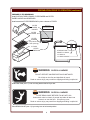
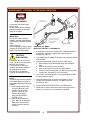
7
FILTER
PUMP &
MOTOR
FRYPOT
POWER
CORD
CONDUIT
FITTING
90º
Fig. 2 Field Wiring
PREPARATION PRIOR TO OPERATION
WARNING
WARNING:
BURN HAZARD
TURN THERMOSTAT TO LOWEST TEMPERATURE SETTING
(FULLY COUNTERCLOCKWISE)
USE ONLY LOW-FOAMING COMMERCIAL FRYER CLEANSER.
CAREFULLY FOLLOW CLEANSER INSTRUCTIONS AND WARNINGS.
DO NOT LEAVE FRYER UNATTENDED
WHILE BOILING OUT FRYPOT.
WHEN WATER BEGINS FOAMING,
BE PREPARED TO TURN POWER SWITCH OFF.
Boiling water and splatter can result in moderate to serious injury.
Prior to leaving the factory,
each fryer is tested for proper
operation. Oil residue must be
cleaned from the frypot before
filling it with fresh oil.
IMPORTANT:
Use a LOW-FOAMING
COMMERCIAL fryer cleanser
only.
PRE-CLEANING PROCEDURE
Press POWER SWITCH OFF.
Close DRAIN VALVE (lever horizontal).
Fill FRYPOT with 4 gallons of cold water.
Press POWER SWITCH to FRYER.
When water comes to a full boil, press POWER SWITCH OFF.
When boiling ceases, slowly add and stir in the LOW FOAMING
COMMERCIAL FRYER CLEANSER. Using the HIGH
TEMPERATURE BRUSH supplied with the fryer, stir until the cleanser is completely dissolved.
Press POWER SWITCH OFF. Allow the solution to cool to 120ºF or
less.
CRADLE
PIVOT
Place a suitable METAL container under the DRAIN VALVE. Open
DRAIN VALVE (lever vertical) to drain the cleaning solution.
NOTE: Drain no more than 4” at a time into the container to prevent
splashing and spilling. Dispose of used solution as required by local
ordinances.
Rinse frypot with clean water. Dry with a soft clean cloth.
CRADLE
LIFT ROD
Wash LIFT CRADLE in a dishwasher. Be sure cradle is completely
dry, then install LIFT CRADLE onto CRADLE LIFT ROD.
LIFT
CRADLE
8
361 2M-301669 Owners Manual WFAE-30F Free-Standing 30# Electric Fryer
Press POWER SWITCH to FRYER. When the water begins to boil,
press POWER SWITCH OFF. When the boiling subsides, again
press POWER SWITCH to FRYER. Repeat this procedure
continuously for five (5) minutes.
PREPARATION PRIOR TO OPERATION (continued)
PREPARE FILTER RESERVOIR
Install SUCTION TUBE O-RINGS, FILTER PAPER and FILTER
PAPER HOLDER into RESERVOIR.
Install assembled FILTER RESERVOIR in place a bottom of FRYER.
FILTER
PAPER
HOLDER
RESERVOIR
ASSEMBLY
CROSS-SECTION VIEW
FILTER
PAPER
FILTER
SCREEN
(clip inserts into
drain opening)
“O” RING
FILTER
RESERVOIR
STORAGE FOR 3
SPARE “O” RINGS
361 2M-301669 Owners Manual WFAE-30F Free-Standing 30# Electric Fryer
“O” RING IN
“O” RING GROOVE
WARNING
WARNING:
SLIP/FALL HAZARD
DO NOT OPERATE UNLESS DRIP PAN IS INSTALLED.
Oil will drip on the floor and slips/falls will result.
Death or serious injury may result from slipping and falling in spilled oil.
Install DRIP PAN (item 17) into mounting bracket behind fryer door.
WARNING
WARNING:
SLIP/FALL HAZARD
CLOSE DRAIN VALVE BEFORE FILLING WITH OIL.
Unless drain valve is closed, oil poured into kettle will drain into
reservoir or onto the floor. Oil spill may occur.
Death or serious injury may result from slipping and falling in spilled oil.
Close DRAIN VALVE (item 11) by turning lever to horizontal position.
9
PREPARATION PRIOR TO OPERATION (continued)
NOTE:
Fill the FRYPOT to the COLD (MAX) line on OIL LEVEL INDICATOR
with room temperature commercial-quality LIQUID SHORTENING.
This requires 30lbs. of oil.
Fill frypot with 30 lbs of
LIQUID SHORTENING
ONLY.
LOWER CONTROL PANEL
UPPER CONTROL PANEL
THERMOSTAT
FILTER
WELLS
MAX (COLD)
30 LB. 13KG OIL LEVEL
MIN (HOT)
SET
COOK
TIME
B
U
Z
Z
E
R
350
HI-LIMIT
RESET
OFF
CAUTION
FRYER MUST BE OFF
BEFORE USING FILTER
250
375
275
ºF
FRYER
OIL LEVEL INDICATOR
SET COOK
TEMPERATURE
OFF
FILTER
DO NOT USE
SOLID SHORTENING
LARD
START
COOK
CYCLE
COOK
HEAT
POWER
•
•
325
300
ON
POWER SWITCH (FILTER-OFF-FRYER)
Solid shortening will solidify in
the filter reservoir and filter
pump rendering the filtration
system inoperable.
Damage caused the use of
anything other than liquid
shortening is NOT COVERED
BY WARRANTY.
DRIP
PAN
WELLS
FRYER
OFF
FILTER
POWER
HEAT
COOK
FILTER
RESET HI-LIMIT
FILTER PUMP
SWITCH
DRAIN
VALVE
THERMOSTAT
325
300
ON
HI-LIMIT
350
275
375
RESET
OFF
CAUTION
FRYER MUST BE OFF
BEFORE USING FILTER
250
DRAIN
VALVE
LEVER
ºF
FILTER
RESERVOIR
Check operation of FRYER and all CONTROLS.
WARNING
WARNING:
OIL SPLATTER HAZARD
FAILURE TO DETERMINE THE SAFE WEIGHT OF PRODUCT
WILL RESULT IN HOT OIL RELEASE FROM THE FRYER
HOT OIL WILL CAUSE SEVERE BURNS ON CONTACT
Death or serious injury may result from slipping and falling in spilled oil.
IMPORTANT:
For operational safety it is
important to determine the maximum load weight for the specific operation:
• Start with small loads
• Gradually increase load
size
• Determine the largest load
that will allow a full cook
cycle without oil foaming
out of the frypot.
• Post the maximum load in a
conspicuous spot near the
fryer.
DETERMINE MAXIMUM LOAD WEIGHT:
For operational safety, it is very important to determine the maximum
load weight for the specific operation. This can be accomplished by
starting out with small loads and gradually increasing to the largest
load size that will allow a cook cycle to be completed without oil
foaming out of the FRYPOT.
10
361 2M-301669 Owners Manual WFAE-30F Free-Standing 30# Electric Fryer
The weight of product that can safely be cooked in this pressure fryer
will vary with oil level, product moisture content and oil temperature.
OPERATION
PRE-HEATING FRYER
CAUTION:
Make sure FRYPOT is filled with 30 LB. of cooking oil.
BURN HAZARD
Open door and set THERMOSTAT (item 10) to desired cooking
temperature. CLOSE THE DOOR.
Set POWER SWITCH (item 1) to FRYER. POWER LIGHT (item 2)
and HEAT LIGHT (item 3) will glow. HEAT LIGHT will cycle on and
off with the HEATING ELEMENTS. When HEAT LIGHT first goes off,
fryer is ready to cook the product.
Hot oil can cause serious burns
on contact. Wear appropriate
protective clothing when using
this fryer.
IMPORTANT:
Always remove basket handle
from basket before lowering lift
cradle.
SET COOK TIMER AND LOAD PRODUCT
Set TIMER (item 5) to desired cooking time.
FROZEN PRODUCT:
Load frozen product into BASKET. Using the BASKET HANDLE
(item 16) set BASKET on LIFT CRADLE.
IMPORTANT: REMOVE HANDLE.
Press RED BUTTON on TIMER to lower BASKET into FRYPOT.
FRESH PRODUCT:
Using BASKET HANDLE, set BASKET on LIFT CRADLE.
IMPORTANT: REMOVE THE HANDLE.
Press the red button on TIMER to lower BASKET into FRYPOT.
Manually drop each piece of fresh product into hot oil, just above
the oil level to minimize splattering.
ALWAYS USE PROTECTIVE EQUIPMENT, SUCH AS INSULATED
GLOVES, TO PROTECT AGAINST HOT OIL BURNS
TURN TO SET TIME
PRESS RED BUTTON TO START TIMER
361 2M-301669 Owners Manual WFAE-30F Free-Standing 30# Electric Fryer
COOK CYCLE AND BUZZER
When an audible alarm is desired at end of cook cycle, turn BUZZER
SWITCH (item 7) ON after TIMER has been started. BUZZER LIGHT
(item 6) will glow.
Note: If BUZZER SWITCH is turned ON before BASKET is lowered,
BUZZER will sound until BASKET has fully lowered.
At end of cook cycle, BASKET will raise and BUZZER will sound until
BUZZER SWITCH is turned OFF, or until the next cook cycle is started.
Use BASKET HANDLE (item 16) to remove basket of cooked product
from LIFT CRADLE. Serve or dispense cooked product as required.
11
8
9
10 11 12
7
13
14
6
15
16
5
4
17
3
18
2
19
20
1
21
0
TIMER
MAINTENANCE - FILTER OPERATION
WARNING
WARNING:
BURN HAZARD
HOT OIL SPILL OR SPLATTER
DO NOT REMOVE FILTER RESERVOIR WHEN IT CONTAINS HOT OIL
HOT OIL WILL CAUSE SEVERE BURNS ON CONTACT
PROTECTIVE CLOTHING AND GLOVES MUST BE WORN
DURING THE FILTERING PROCESS
Death or serious injury may result from contact with, or slipping and falling in, spilled oil.
WARNING
WARNING:
BURN HAZARD
DO NOT REMOVE FILTER RESERVOIR IF IT IS HOT
WEAR PROTECTIVE GLOVES OR
ALLOW RESERVOIR TO COOL BEFORE REMOVING
Oil will rapidly heat the reservoir. Serious burns can result
from touching the filter reservoir with bare hands.
IMPORTANT:
Replace filter paper after each
day’s filtration, or as needed to
return oil promptly to kettle.
1. Open FRYER DOOR and remove FILTER RESERVOIR.
2. Remove FILTER PAPER HOLDER, used FILTER PAPER and
FILTER SCREEN. Discard used filter paper and make sure filter
reservoir, filter screen and filter paper holder are clean and dry.
3. Install FILTER SCREEN in reservoir with spring clip on screen
pressed firmly into drain hole, and aligned parallel to sides of
reservoir. See diagram, page 9.
4. Place a NEW SHEET of filter paper on reservoir, with edges of
the paper evenly overhanging reservoir flanges.
5. Center FILTER PAPER HOLDER over filter paper, then press
firmly into reservoir. Make sure filter paper holder rests firmly on
reservoir bottom, with paper protruding evenly up all sides.
6. Inspect O-RING on FILTER SUCTION TUBE for damage.
Replace o-ring if it is scuffed, cut or cracked. Spare o-rings are
stored midway on the top portion of the suction tube.
7. Install filter reservoir assembly into fryer. Make sure o-ring
closest to end of suction tube is firmly seated in SUCTION LINE
RECEPTACLE.
12
361 2M-301669 Owners Manual WFAE-30F Free-Standing 30# Electric Fryer
IMPORTANT:
Crumbs and other debris left in
the filter reservoir can prevent
filter paper from sealing to
bottom of reservoir completely.
This will cause incomplete
filtration.
FILTER PAPER INSTALLATION
MAINTENANCE - FILTER OPERATION (continued)
FILTERING OIL
CAUTION
NOTE: For operation of optional filter wand, see page 16.
BURN HAZARD
NOTE:
Oil should be at least 300ºF (149ºC) DO NOT attempt to filter cold oil.
DO NOT attempt to pump oil when less than 300ºF. Cold oil will not
pass through the filter paper. Filtering cold oil will result in the
premature failure of the filter pump. Damage as a result of pumping
cold oil IS NOT COVERED BY WARRANTY.
NOTE:
DO NOT store oil in the reservoir for any extended period, including
overnight.
IMPORTANT:
The filtration system in your Wells Fryer is designed to filter hot liquid
shortening ONLY. Water, cleaning agents or other liquids will
damage the filter pump and may contaminate the food product
1. Press POWER SWITCH (item 1) to FILTER. Pump controls will
be energized and heating elements are de-energized.
2. Remove and examine filter reservoir:
• Verify that a serviceable sheet of filter paper is properly
installed.
• Verify that an o-ring is in place and in good condition.
Reinstall reservoir, making sure the SUCTION TUBE is firmly
seated in the SUCTION RECEPTACLE.
361 2M-301669 Owners Manual WFAE-30F Free-Standing 30# Electric Fryer
3. Press FILTER PUMP SWITCH (item 8) to ON to start filter pump.
4. Slowly rotate DRAIN VALVE LEVER (item 11) to the vertical
position. Oil will drain from the frypot and into the reservoir. The
filter pump will draw oil through the filter paper and return it to the
frypot.
IMPORTANT:
DO NOT leave the fryer unattended during the filtering process.
Continuously monitor oil level in the reservoir to avoid overflowing
the reservoir and spilling oil on the floor. Be prepared to turn the
drain valve lever clockwise to stop or regulate the flow of oil to the
reservoir.
5. Carefully and slowly add the contents of one package of FILTER
POWDER to the oil in the frypot. Sprinkle the filter powder onto
the surface of the oil at the point where it is being drawn down the
drain and into the filter reservoir.
(CONTINUED ON PAGE 14)
13
Protective clothing and gloves
must be worn during the filtering
process
CAUTION
BURN HAZARD
Filter reservoir may be hot.
Wear insulated gloves, or
allow reservoir to cool,
before touching it.
IMPORTANT:
Filtering cooking oil helps to
ensure the quality of the food
product. Careful observation of
the finished food product will
help you determine the optimal
filtering frequency.
(Example: Filter the oil after
each six loads of fresh breaded
chicken)
FILTER POWDER absorbs
acids and many other
contaminants in the cooking oil,
allowing the oil to be used longer before it must be
replaced. Wells Flavor Saver Oil
Filter Powder is available from
your Wells Equipment Dealer or
Authorized Service Agent in a
case of 45 packages
(p/n 22410).
NOTE: On fryers equipped
with optional FILTER WAND,
oil stream from the wand may
be directed at the sides of the
frypot to wash down crumbs
and cooking debris.
See page 16.
MAINTENANCE - FILTER OPERATION (continued)
WARNING
WARNING:
BURN HAZARD
WEAR PROTECTIVE CLOTHING AND INSULATED GLOVES
WHEN CLEANING FRYPOT WITH HI-TEMP BRUSH AND WHEN
CLEARING DRAIN WITH WOOD CLEANOUT DOWEL.
Frypot and oil will be hot. Hot oil may splatter.
Contact with hot oil can cause serious injury
NOTE:
Use the provided WOOD DOWEL to clear clogs in the frypot
drain. Push dowel down
through drain hole in the front
center of the frypot..
(CONTINUED FROM PAGE 13)
6. Brush down sides and bottom of frypot using provided
hi-temperature brush. Loosen crumbs and other debris to flush
them into filter reservoir.
7. Rotate DRAIN VALVE LEVER (item 11) to the horizontal position
when filtering is complete,
IMPORTANT:
Verify that all oil has been
returned to frypot at end of
filtering cycle.
8. Observe the oil returning to frypot. When bubbles appear, wait
approximately 15 seconds, then press FILTER PUMP SWITCH
to OFF.
9. Press POWER SWITCH to either:
a. FRYER position to resume cooking; or,
b. OFF position to service filter or shut-down fryer.
FILTER SERVICE - REPLACE FILTER PAPER
IMPORTANT:
Service filter and replace filter paper after each day’s filtration, or as
needed to promptly return oil to frypot.
1. Allow FILTER RESERVOIR to cool. Remove reservoir from fryer
and disassemble.
IMPORTANT:
Avoid contaminating the oil or
food product by verifying that all
components of filter reservoir
assembly are completely dry
before reassembling.
2. Dispose of used filter paper as required by local ordinances.
3. Clean FILTER RESERVOIR, FILTER SCREEN and FILTER
PAPER HOLDER in the dishwasher, or use warm water with a
mild detergent. Be sure all components are thoroughly dry, then
reassemble reservoir using a fresh sheet of filter paper.
14
361 2M-301669 Owners Manual WFAE-30F Free-Standing 30# Electric Fryer
IMPORTANT:
Crumbs and other debris left in
the filter reservoir can prevent
filter paper from sealing to
bottom of reservoir completely.
This will cause incomplete
filtration.
MAINTENANCE - DISCARDING USED OIL
WARNING
WARNING:
BURN HAZARD
OIL MUST COOL TO BELOW 120ºF (49ºC)
BEFORE DRAINING OIL FROM FRYER FOR DISPOSAL
Normal operating temperature of the fryer is 375ºF (191ºC)
Contact with hot oil can cause serious injury
WARNING
WARNING:
SLIP AND FALL HAZARD
DO NOT USE FILTER RESERVOIR TO DISCARD OIL
USE A METAL CONTAINER TO COLLECT OIL FOR DISPOSAL
DO NOT FILL DISPOSAL CONTAINER MORE THAN ½ FULL
Do not leave fryer unattended when draining oil
Oil spills may occur
Death or serious injury may result from contact with, or slipping and falling in, spilled oil.
WARNING
WARNING:
BURN HAZARD
DO NOT REMOVE FILTER RESERVOIR IF IT IS HOT
WEAR PROTECTIVE GLOVES OR
ALLOW RESERVOIR TO COOL BEFORE REMOVING
361 2M-301669 Owners Manual WFAE-30F Free-Standing 30# Electric Fryer
Oil will rapidly heat the reservoir. Serious burns can result
from touching the filter reservoir with bare hands.
DISCARDING USED OIL
NOTE: To use optional wand for discarding used oil, see page 16.
1. Press POWER SWITCH to OFF. Allow oil to cool to 120ºF (49ºC)
or less before attempting to drain oil from fryer.
2. Remove FILTER RESERVOIR ASSEMBLY. With a suitable
METAL container under DRAIN VALVE, slowly rotate DRAIN
VALVE LEVER to the vertical position. Fill the container no more
than 4” (100mm) deep.
3. Move the DRAIN VALVE LEVER to the horizontal position.
4. Carefully remove container from under fryer. Dump used oil into
your WASTE OIL CONTAINER. Repeat steps 2 & 3 until frypot is
empty.
5. Be sure DRAIN VALVE LEVER is in the CLOSED (horizontal)
position when finished.
6. Service FILTER RESERVOIR ASSEMBLY and reinstall .
15
IMPORTANT NOTE:
These instructions for
discarding used oil may be
disregarded if you are using
WELLS MOBILE OIL CADDY
WOC-1 (p/n 22470).
The WAOC-1 is a manual oil
pump/removal system that
allows you to pump used oil
directly into the caddy, and then
to pump the used oil into your
oil disposal container simply by
reversing pump direction.
REMEMBER:
Always follow the directions
provided with the caddy.
WAOC-1 is designed to handle
COLD oil. Always, and without
fail, allow the oil to cool to
120ºF or less prior to pumping.
HOT OIL WILL BURN YOU!
MAINTENANCE - OPTIONAL FILTER WAND OPERATION
DANGER:
DRAIN "OPEN"
(HANDLE VERTICAL)
BURN HAZARD
Contact with hot oil will cause
severe burns.
Always wear protective clothing
and heat resistant gloves when
using the oil wand.
IMPORTANT:
Be sure the wand is properly
installed, and that the discharge
nozzle of the oil wand is directed
either:
into the frypot, or
into the disposal container, before
pressing the FRYER-OFF-FILTER
switch to the FILTER position.
CAUTION:
BURN HAZARD
WAND PROPERLY
CONNECTED
D
TO
N
WA
OPTIONAL OIL WAND
WASH OUT FRYPOT or DISCARD OIL
1. If discarding oil, be sure a suitable hot oil disposal container
is available. Otherwise, prepare filter reservoir pan for
filtering (see page 12).
2. Turn DRAIN VALVE HANDLE vertical to open the drain and fill
filter reservoir.
3. Connect wand (female) fitting to the fryer (male) fitting:
a. Slide locking ring of wand female fitting fully toward the
hose.
b. Seat wand fitting fully onto fryer fitting.
c. Allow locking ring to return to its original position.
d. Check to verify that wand fitting is held securely by pulling
on the hose. It must NOT “pop” off of fitting.
4. Turn 3-WAY VALVE HANDLE to horizontal position to direct
the pump output to wand.
NOTE:
If the discharge from the nozzle is
not a steady stream, the filter is
clogged with breading and/or filter
powder:
a. Close the frypot drain valve
by turning the drain valve
handle to the horizontal
position. When all oil is
returned to the frypot,
press the FRYER-OFFFILTER to OFF.
b. Allow the filter reservoir to
cool. Refer to the Operation
Manual for instructions on
cleaning the filter and filter
reservoir.
5. Direct discharge nozzle of wand into the frypot, or into a
suitable hot oil disposal container. DO NOT fill beyond
the MAX OIL line.
6. Press FRYER-OFF-FILTER switch to FILTER position.
7. Wand may be used to wash down sides of the frypot during
filtering, or to pump oil into a container for disposal.
16
361 2M-301669 Owners Manual WFAE-30F Free-Standing 30# Electric Fryer
Contact with hot oil may cause
burns. DO NOT fill fryer beyond
MAX OIL line on frypot.
For disposal of oil use only a
container specifically designed
for the disposal of hot oil.
DO NOT fill hot oil disposal
container beyond MAX OIL line.
3-WAY VALVE TO "WAND"
(HANDLE HORIZONTAL)
MAINTENANCE - OPTIONAL FILTER WAND OPERATION (continued)
HEATER SAFETY SWITCH
("SAFE" WHEN DRAIN
HANDLE FULLY CLOSED)
DANGER:
BURN HAZARD
Contact with hot oil will cause
severe burns.
Always wear protective clothing
and heat resistant gloves when
operating the fryer.
DRAIN "CLOSED"
(HANDLE HORIZONTAL)
CAUTION:
FRYER
3-WAY VALVE
TO “FRYPOT”
(HANDLE
VERTICAL)
OFF
FILTER
OPTIONAL OIL WAND
RETURN FRYER TO NORMAL OPERATION
1. After washing down frypot, turn DRAIN VALVE HANDLE
horizontal to close the frypot drain.
361 2M-301669 Owners Manual WFAE-30F Free-Standing 30# Electric Fryer
IMPORTANT: Drain handle must be fully closed in order to
activate HEATER SAFETY SWITCH. Drain handle must be
horizontal before for fryer heating element can be energized.
2. At conclusion of use, press FRYER-OFF-FILTER switch to
OFF position, disconnect wand from fryer fitting and return
handle of the 3-WAY VALVE to the vertical position.
3. Drain any remaining oil in wand by pointing discharge nozzle
of wand down into frypot or disposal container.
4. Be sure 3-WAY VALVE HANDLE is vertical.
Press FRYER-OFF-FILTER switch to FILTER position.
When all oil has been returned to frypot, press FRYER-OFFFILTER switch to FRYER position to resume operation, or to
OFF position to shut down.
17
BURN HAZARD
Overflow of hot oil may cause
burns. DO NOT fill fryer beyond
MAX OIL line on frypot.
IMPORTANT:
When refilling the frypot, be
sure the 3-way valve handle is
vertical, and the drain valve
handle is horizontal before
pressing FRYER-OFF-FILTER
switch to the FILTER position.
MAINTENANCE - CLEANING INSTRUCTIONS
DANGER: BURN HAZARD
Contact with hot oil will cause severe burns. Allow the fryer to cool before cleaning.
Always wear protective clothing and heat resistant gloves when cleaning the fryer.
CAUTION:
PREPARATION
Press POWER SWITCH to OFF
Allow fryer to cool completely before cleaning
Disconnect fryer from electric power before
cleaning
FREQUENCY
Daily, or as needed
TOOLS
Mild Detergent, Non-abrasive cleanser
Soft Cloth or Sponge, Plastic Scouring Pad
ELECTRIC SHOCK
HAZARD
Disconnect fryer from electric
power before cleaning.
CAUTION:
BURN HAZARD
DAILY CLEANING
Allow fryer to cool completely
before cleaning.
IMPORTANT: DO NOT spill
or pour water into controls,
control panel or wiring.
2. Remove FRY BASKET, LIFT CRADLE and FILTER RESERVOIR
ASSEMBLY.
IMPORTANT: Clean reservoir only when empty.
3. Allow the oil to cool to a safe temperature (120ºF or less).
4. Fry basket and lift cradle may be washed in a dishwasher, or with
warm water and mild detergent. Rinse thoroughly and dry
completely.
5. Clean FILTER RESERVOIR, FILTER SCREEN and FILTER
PAPER HOLDER in the dishwasher, or use warm water with a
mild detergent. Be sure all components are thoroughly dry, then
reassemble reservoir using a fresh sheet of filter paper.
IMPORTANT: Be sure inside of RESERVOIR SUCTION TUBE is
completely dry.
6. Keep all exterior surfaces free from splashed grease by wiping with
a clean cloth dampened with warm water and mild detergent.
• Clean both exterior and interior of FRYPOT COVER.
• Clean side, front and accessible interior areas of cabinet.
• A non-abrasive detergent and plastic scouring pad may be
used for stubborn deposits.
• Dry with a soft clean cloth.
IMPORTANT: DO NOT use steel wool or abrasive cleansers
as these will damage the surface finish.
IMPORTANT: DO NOT spill or pour water into controls, control
panel or wiring. Damage to internal components will occur.
7. Reinstall FRY BASKET, LIFT CRADLE and FILTER RESERVOIR
ASSEMBLY.
Procedure is complete.
18
361 2M-301669 Owners Manual WFAE-30F Free-Standing 30# Electric Fryer
122 306626 OpManual for HDG-Series Griddles
122 306626 OpManual for HDG-Series Griddles
IMPORTANT: DO NOT use
steel wool or abrasive
cleansers for cleaning the
fryer cabinet or frypot.
1. Press POWER SWITCH to OFF.
MAINTENANCE - CLEANING INSTRUCTIONS (continued)
WARNING
WARNING:
BURN HAZARD
TURN THERMOSTAT TO LOWEST TEMPERATURE SETTING
(FULLY COUNTERCLOCKWISE)
USE ONLY LOW-FOAMING COMMERCIAL FRYER CLEANSER.
CAREFULLY FOLLOW CLEANSER INSTRUCTIONS AND WARNINGS.
DO NOT LEAVE FRYER UNATTENDED
WHILE BOILING OUT FRYPOT.
WHEN WATER BEGINS FOAMING,
BE PREPARED TO TURN POWER SWITCH OFF.
Boiling water and splatter can result in moderate to serious injury.
PREPARATION Drain oil from fryer before cleaning
FREQUENCY
Monthly, or as needed
TOOLS
Low-foaming commercial fryer cleanser
Metal disposal container
FRYPOT CLEANING - HOT BOILOUT PROCEDURE
Raise FRYPOT COVER (if closed). Press POWER SWITCH OFF.
Close DRAIN VALVE (lever horizontal). Fill FRYPOT with 4 gallons of
cold water.
361 2M-301669 Owners Manual WFAE-30F Free-Standing 30# Electric Fryer
Press POWER SWITCH to FRYER.
When water comes to a full boil, press POWER SWITCH OFF. When
boiling ceases, slowly add and stir in the LOW FOAMING COMMERCIAL FRYER CLEANSER. Using the HIGH
TEMPERATURE BRUSH supplied with the fryer, stir until the cleanser is completely dissolved.
Press POWER SWITCH to FRYER. When the water begins to boil,
press POWER SWITCH OFF. When the boiling subsides, again press
POWER SWITCH to FRYER. Repeat this procedure
continuously for five (5) minutes.
Press POWER SWITCH OFF. Allow the solution to set for thirty (30)
minutes.
Allow solution to cool to 120ºF (49ºC) or less before draining.
Place a suitable METAL container under the DRAIN VALVE. Open
DRAIN VALVE (lever vertical) to drain the cleaning solution.
NOTE: Drain no more than 4” at a time into the container to prevent
splashing and spilling. Dispose of used solution as required by local
ordinances.
Rinse frypot with clean water. Dry with a soft clean cloth.
19
IMPORTANT:
Use a LOW-FOAMING
COMMERCIAL fryer cleanser
only.
IMPORTANT:
DO NOT press FILTER PUMP
SWITCH to ON with anything
other than shortening in the
filter reservoir. Water and/or
cleaning chemicals can:
• cause severe oil splatter
• damage the filter pump
• contaminate cooking oil
and food product.
TROUBLESHOOTING
SYMPTOM
Fryer will not heat
Lift cradle will not lower
Lift cradle will not raise
Filter pump will not run
or pump overload trips frequently
Filter pump won’t pump, or pumps air
when filtering
SUGGESTED REMEDY
Unit disconnected from electric power
Reconnect to power
Check/reset circuit breaker
Temp control thermostat (item 10) not set
Set thermostat to desired temperature
Hi-Limit thermostat (item 9) tripped
Allow unit to cool, reset hi-limit
See page 3
Fryer safety switch not made
(fryer with optional wand only)
Be sure drain lever is horizontal
Internal damage
Contact your Authorized Wells Service
Agency for repairs
Timer not set or not activated
Set timer to other than “0”, press red
button to lower cradle.
Internal damage or mis-adjustment
Contact your Authorized Wells Service
Agency for repairs
Lift cradle not properly assembled to lift
rod
Properly assemble cradle pivot to lift rod
Internal damage or mis-adjustment
Contact your Authorized Wells Service
Agency for repairs
Switches not set for filtering
Press power switch (item 1) to FILTER
Press pump filter switch (item 6) to ON
Pump overload (item 9) tripped
Reset overload. Press red button until it
“clicks” and stays locked in
(Fryer with optional wand only) 3-way
valve not in “frypot” position
Be sure valve is in “frypot” position, or
that valve is in “wand” position with wand
fully seated in quick disconnect fitting.
Internal damage (pump overload trips
frequently)
Contact your Authorized Wells Service
Agency for repairs
Drain valve (item 11) not properly set
Oil level in reservoir must be manually
monitored at all times while filtering.
Adjust flow by opening or closing drain
valve
Filter paper surface clogged with crumbs
or other cooking debris
Turn drain valve OFF. When bubbles
begin appearing in frypot turn filter pump
switch OFF. Carefully slide reservoir out
6” and clear surface of filter paper with hi
-temp brush or wooden dowel. Reinstall
reservoir and resume filtering.
Suction tube not seated, allowing air to
enter system
When inserting filter reservoir be sure
suction tube is fully seated in suction line
receptacle.
Suction tube o-ring damaged
Replace o-ring
Internal damage
Contact your Authorized Wells Service
Agency for repairs
NOTE: There are no user serviceable
components in the fryer. In all cases of
damage or malfunction, contact your
Authorized Wells Service Agency for
repairs.
20
361 2M-301669 Owners Manual WFAE-30F Free-Standing 30# Electric Fryer
Filter reservoir overflows
during filter cycle
POSSIBLE CAUSE
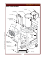
EXPLODED VIEW & PARTS LIST
WFAE-30F CABINET COMPONENTS
ASSEMBLY,
CRADLE LIFT ACTUATOR
DD-69828
HANDLE, DOOR
2R-38668
BUSHING
2K-47357 (2 places)
ASSEMBLY, FRYPOT
E7-47339
COVER, FRYPOT
E7-47384
PIN, HOLD DOWN COVER
2A-47343 (2 places)
BLOCK, HINGE
DD-67345 (2 places)
GUARD
E7-300527
FACEPLATE
2M-302391
361 2M-301669 Owners Manual WFAE-30F Free-Standing 30# Electric Fryer
CLAMP, FRYPOT
E7-46724 (2 places)
CLAMP, TOP FRYER
67332 (2 places)
MAGNET, DOOR
2R-46502
TUBE, SILICONE
.375 IDx 24-1/4”
E7-70906
FITTING,
SUCTION LINE
E7-46720
ASSEMBLY, DOOR
DD-61713
(includes 2R-38668
HANDLE)
HANDLE, DOOR
(only) 2R-38668
CASTER, RIGID 5”
2P-47011 (2 places)
CONDENSATE
TRAY
E7-46711
NOT SHOWN
PANEL, RIGHT SIDE E7-46722
PANEL, LEFT SIDE E7-46723
21
LEG, ADJUSTABLE
6” to 7-1/4”
2A-46480 (2 places)
IL1891A
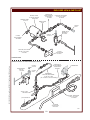
EXPLODED VIEW & PARTS LIST
LIFT ACTUATOR & MOTOR ASSEMBLY &
HEATING ELEMENTS & ELECTRICAL CONTROL COMPONENTS
*CAM, ACTUATOR
*BUSHING
*MOTOR, LIFT
2E-49826
2K-47357 (2 places)
*BEARING,
*ACTUATOR,
TRACK
2P-30483
LIFT E7-WL0034
2U-47366
*MICROSWITCH
2E-30198
*INSULATOR,
MICROSWITCH
E7-47085
*
*
*THESE PARTS AND
ASSOCIATED FASTENERS
INCLUDED IN ASSEMBLY,
CRADLE LIFT ACTUATOR
DD-69828
WASHER,
FIBER
2I-Z12311
*
LIF
TA
SS
SWITCH
FRY/OFF/FILTER
2E-49550
EM
BL
Y
*
LIGHT,
SIGNAL AMBER
2J-30516 (4 places)
FITTING, FLEX
CONDUIT 3/8 x 90º
2K-33996X
BUZZER 2E-44835
SWITCH, BUZZER
2E-45651
TIMER ASSEMBLY
2P-48469
ELEMENT, HEATING 208V 9000W WS-66664
ELEMENT, HEATING 240V 9000W WS-66691
PE
RC
ON
TR
OL
CO PAN
NT EL
RO
L
FR
YP
SAFETY CLAMP
ELEMENT, 2C-49689
(6 places)
OT
BO
X
LO
WE
RC
ON
TR
OL
PA
N
EL
GASKET, ELEMENT
WS-66863
CONTACTOR
3P 40A 208/240V
2E-Z14960
TERMINAL BLOCK
3P (DOMESTIC) 2E-30412
4P (EUROPEAN) WS-57465 SWITCH, FILTER
DD-47052
THERMOSTAT,
TEMPERATURE CONTROL
WS-66688
THERMOSTAT,
HI-LIMIT SAFETY
WS-66663
KNOB, TEMP. CONTROL
2R-45653
22
IL1892A
361 2M-301669 Owners Manual WFAE-30F Free-Standing 30# Electric Fryer
UP
*
*
EXPLODED VIEW & PARTS LIST
CHECKVALVE
3/8 NPT FEMALE x
3/8 NPT MALE
2V-46692
MOTOR, FILTER
1ø 125/230v 50/60 Hz
WS-501205
WASHER, FIBER
2I-Z12311
FLEX LINE, DISCHARGE
.6” OD x 9.5” LONG
2J-302289
PUMP, FILTER
501231
FRYPOT
INLET
DRAIN VALVE
W/HANDLE
E7-303769
FRYPOT
OUTLET
FITTING,
FLEX CONDUIT
2K-33996X
FLEX LINE, SUCTION
.75” OD x 16.5” LONG
2J-302287
FITTING,
SUCTION LINE
E7-46720
STANDARD FRYER
361 2M-301669 Owners Manual WFAE-30F Free-Standing 30# Electric Fryer
FRYER W/ OPTIONAL OIL WAND & DRAIN SAFETY SWITCH
CHECKVALVE
3/8 NPT FEMALE x
3/8 NPT MALE
2V-46692
FRYPOT
OUTLET
MICROSWITCH
120V 15A
2E-44887
PUMP/MOTOR
FRYPOT
INLET
MAKE FROM
FLEX LINE, DISCHARGE
.6” OD x 32” LONG
(ref. 2J-303094 - discard end fittings)
VALVE, 3-WAY
DD-304309
FLEX LINE, DISCHARGE
.6” OD x 9.5” LONG
2J-302289
part of DD-304734
OIL WAND
& HOSE ASSY
DD-304734
IL1893
23
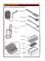
EXPLODED VIEW & PARTS LIST
WFAE-30F ACCESSORIES & REMOVEABLE COMPONENTS
PADDLE, STIRRING
CHICKEN 2B-302203
BRUSH, CLEANING FRYER
(HI-TEMP) 2P-302204
FRY BASKET
(STD) WS-22685
BASKET HANDLE
E7-300249
BRUSH, CLEANING
ELEMENT 2P-46479
DOWEL, CLEANOUT
FRYER 2C-49752
PIVOT, CRADLE
MOUNT 2A-47349
CRADLE
E7-47353
FILTER PAPER
2I-46507 (pk 100)
OPTIONAL LEAF FILTER
2I-301847
FILTER SCREEN
E7-46446
O-RING
2I-46474
FILTER RESERVOIR
E7-305626
O-RING FOR
FILTER LEAF (not shown)
WS-501900
FLAVOR-SAVER
FILTER POWDER
(not shown)
2M-301698
26
361 2M-301669 Owners Manual WFAE-30F Free-Standing 30# Electric Fryer
FILTER PAPER
HOLDER E7-304829
24
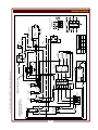
20A
16
C
7
27
20
12
FUSES (2)
15A MAX
POWER
SWITCH
22
12A
L1
1
13
L2
2
15
POWER
LIGHT
1Ø OR 3Ø, 208V OR 240V, 9KW w/BUZZER
WIRED 3Ø AS SHOWN
WFAE-30F & FAE-30F
L3
3
8
32
15
TERMINAL
BLOCK
CONTACTOR
9
HEAT-ON
LIGHT
19
11
24
7
8
LOWER CONTROL BOX
UPPER CONTROL BOX
COOK
LIGHT
FILTER
SWITCH
TERMINATE TIMER MOTOR LEADS
W/ 3/16 INS PO TERM. (P/N 2C-38898)
25
26
21
6
5
4
361 2M-301669 Owners Manual WFAE-30F Free-Standing 30# Electric Fryer
FILTER
MOTOR
22
12
22
32
M
11
21
31
L1
L3
L2
CONTROLLER
THERMOSTAT
TIMER
31
23
17
19
33
18
L3 ELEMENT
L2 ELEMENT
32
BUZZER
21.7
240
L1
25.0
C
13
HI LIMIT
SWITCH
34
L2
21.7
25.0
L3
21.7
25.0
37.5
43.3
60 HZ
1 PHASE
1/4 INS
MALE
LIFT
MOTOR
POSITION
SWITCH
16
M
3
2
1
15
20
1
L2
3
L3
12
8
7
CONTACTOR
SINGLE PHASE
L1
2
TERMINAL BLOCK
SINGLE PHASE
2M-Z13147B
6
5
4
L3
L2
L1
25
SINGLE PHASE CONVERSION
1/4 INS
FEMALE
LIFT
MOTOR
MOTOR LEAD TERMINATED
WITH A 3/16 INS STPO
NOM AMPS PER LINE
16
LIFT
MOTOR
HOUSING
NC
NO
THREE PHASE
208
VOLTS
10
14
35
L1 ELEMENT
36
BUZZER
SWITCH
BUZZER
LIGHT
WIRING DIAGRAM
NOTE
361 2M-301669 Owners Manual WFAE-30F Free-Standing 30# Electric Fryer
24
361 2M-301669 Owners Manual WFAE-30F Free-Standing 30# Electric Fryer
NOTE
25
NOTES
361 2M-301669 Owners Manual WFAE-30F Free-Standing 30# Electric Fryer
28
PARTS & SERVICE
DESCRIPTION
PART NO.
BRUSH, CLEANING HEATING ELEMENT
FILTER PAPER, 30-SERIES FRYER (pk100)
FLAVOR-SAVER OIL FILTER POWDER (pk45)
PADDLE, STIRRING CHICKEN
BRUSH, CLEANING FRYPOT
*FILTER WAND ASSY
2P-46479
2I-46507
5E-22410
2B-302203
2P-302204
DD-304734
*NOTE: The filter wand assembly involves a different plumbing
arrangement than standard fryer. This option must be ordered at time
of initial build and cannot be economically retrofitted to existing fryers.
IMPORTANT: Use only
factory authorized service
parts and replacement
filters.
For factory authorized
service, or to order factory
authorized replacement parts,
contact your Wells authorized
service agency, or call:
Wells Manufacturing
10 Sunnen Dr
St. Louis MO 63143 USA
Service Dept.
phone: (314) 678-6314
fax:
(314) 781-2714
361 2M-301669 Owners Manual WFAE-30F Free-Standing 30# Electric Fryer
Service Parts Department can
supply you with the name and
telephone number of the
WELLS AUTHORIZED
SERVICE AGENCY
nearest you.
CUSTOMER SERVICE DATA
please have this information available if calling for service
RESTAURANT ____________________________ LOCATION _____________
INSTALLATION DATE ______________________ TECHNICIAN ___________
SERVICE COMPANY ______________________________________________
ADDRESS __________________________ STATE ______ ZIP__________
TELEPHONE NUMBER (_____)_____-_________
EQUIPMENT MODEL NO. _______________
EQUIPMENT SERIAL NO. _______________
FUEL (check one)
208VAC
240VAC
29
380-415 3NAC
WELLS MANUFACTURING
10 Sunnen Dr., St. Louis, MO 63143
telephone: 314-678-6314
fax: 314-781-2714
www.wellsbloomfield.com