1
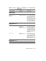
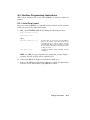
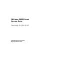
DEClaser 1100 Printer
Installation Guide
Order Number EK–DCL11–IN–002
Digital Equipment Corporation
Maynard, Massachusetts
First Printing, January 1991
Revised, June 1991
The information in this document is subject to change without notice and should not be
construed as a commitment by Digital Equipment Corporation.
Digital Equipment Corporation assumes no responsibility for any errors that may appear in
this document.
Any software described in this document is furnished under a license and may be used or
copied only in accordance with the terms of such license. No responsibility is assumed for
the use or reliability of software or equipment that is not supplied by Digital Equipment
Corporation or its affiliated companies.
Restricted Rights: Use, duplication, or disclosure by the U.S. Government is subject to
restrictions as set forth in subparagraph (c)(1)(ii) of the Rights in Technical Data and Computer
Software clause at DFARS 252.227–7013.
© Digital Equipment Corporation 1991
All rights reserved. Printed in Japan.
The Reader’s Comments form at the end of this document requests your critical evaluation to
assist in preparing future documentation.
The following are trademarks of Digital Equipment Corporation: DECdirect, DEClaser,
DECmailer, DECmate, DECservice, LN03, LN03 Plus, VAX DOCUMENT, and the DIGITAL
logo.
IBM is a registered trademark of International Business Machines Corporation and ProPrinter
is a trademark of International Business Machines Corporation. PostScript is a registered
trademark of Adobe Systems, Inc. HP and LaserJet are registered trademarks of HewlettPackard Company. Microsoft is a registered trademark of Microsoft Corporation. WordPerfect
is a trademark of WordPerfect Corporation.
S1702
This document was prepared using VAX DOCUMENT, Version 1.2.
First Printing, January 1991
Revised, June 1991
The information in this document is subject to change without notice and should not be
construed as a commitment by Digital Equipment Corporation.
Digital Equipment Corporation assumes no responsibility for any errors that may appear in
this document.
Any software described in this document is furnished under a license and may be used or
copied only in accordance with the terms of such license. No responsibility is assumed for
the use or reliability of software or equipment that is not supplied by Digital Equipment
Corporation or its affiliated companies.
Restricted Rights: Use, duplication, or disclosure by the U.S. Government is subject to
restrictions as set forth in subparagraph (c)(1)(ii) of the Rights in Technical Data and Computer
Software clause at DFARS 252.227–7013.
© Digital Equipment Corporation 1991
All rights reserved. Printed in U.S.A.
The Reader’s Comments form at the end of this document requests your critical evaluation to
assist in preparing future documentation.
The following are trademarks of Digital Equipment Corporation: DECdirect, DEClaser,
DECmailer, DECmate, DECserivce, LN03, LN03 Plus, VAX DOCUMENT, and the DIGITAL
logo.
IBM is a registered trademark of International Business Machines Corporation and ProPrinter
is a trademark of International Business Machines Corporation. PostScript is a registered
trademark of Adobe Systems, Inc. HP and LaserJet are registered trademarks of HewlettPackard Company. Microsoft is a registered trademark of Microsoft Corporation. WordPerfect
is a trademark of WordPerfect Corporation.
S1702
This document was prepared using VAX DOCUMENT, Version 1.2.
FCC NOTICE: This equipment generates and uses radio frequency energy
and if not installed and used properly, that is, in strict accordance with the
manufacturer’s instructions, may cause interference to radio and television
reception. It has been type tested and found to comply with the limits
for a Class B computing device in accordance with the specifications in
Subpart J of Part 15 of FCC Rules, which are designed to provide reasonable
protection against such interference in a residential installation. However,
there is no guarantee that interference will not occur in a particular
installation. If this equipment does cause interference to radio or television
reception, which can be determined by turning the equipment off and on,
the user is encouraged to try to correct the interference by one or more of
the following methods.
–
Reorient the receiving antenna.
–
Relocate the computer or peripheral with respect to the receiver.
–
Move the computer or peripheral away from the receiver.
–
Plug the computer or peripheral into a different outlet so that they are
on different branch circuits than the receiver.
If necessary, the user should consult the dealer or an experienced
radio/television technician for additional suggestions. The user may find
the booklet How to Identify and Resolve Radio/TV Interference Problems,
prepared by the Federal Communications Commission, helpful. This
booklet is available from the U.S. Government Printing Office, Washington,
DC 20402, Stock No. 004–000–00345–4.
To meet FCC requirements, a shielded parallel cable is required to connect
the device to a personal computer or other Class B device.
4
Contents
v
Preface
Chapter 1 Preparing Your Site
1.1
1.2
1.3
Power Requirements . . . . . . . . . . . . . . . . . . . . . . . . . . . . . . .
Operating Location Requirements . . . . . . . . . . . . . . . . . . . . .
Environmental Conditions . . . . . . . . . . . . . . . . . . . . . . . . . . .
1–1
1–2
1–3
Chapter 2 Unpacking Your Printer
2.1
2.2
2.3
Printer Inventory . . . . . . . . . . . . . . . . . . . . . . . . . . . . . . . . . .
DEClaser 1100 Printer Components . . . . . . . . . . . . . . . . . . . .
Removing the Shipping Material . . . . . . . . . . . . . . . . . . . . . .
2–1
2–4
2–7
Chapter 3 Installing the EP-L Cartridge
Chapter 4 Connecting the Printer
4.1
4.2
4.3
Serial Interface Connection . . . . . . . . . . . . . . . . . . . . . . . . . .
Parallel Interface Connection . . . . . . . . . . . . . . . . . . . . . . . . .
Power Source Connection . . . . . . . . . . . . . . . . . . . . . . . . . . . .
4–2
4–4
4–5
Chapter 5 Loading Paper
5.1
5.2
5.3
5.4
Loading Paper . . . . . . . . . . . . . . . . . . . . . . . . . .
Turning the Printer Power On . . . . . . . . . . . . . .
Producing the Printer Configuration Data Sheet
Conclusion . . . . . . . . . . . . . . . . . . . . . . . . . . . . .
.
.
.
.
.
.
.
.
.
.
.
.
.
.
.
.
.
.
.
.
.
.
.
.
.
.
.
.
.
.
.
.
.
.
.
.
.
.
.
.
5–2
5–6
5–6
5–7
iii
Appendix A Cabling Information
A.1 Cable Combinations . . . . . . . . . . . . .
A.2 Interface Programming Instructions
A.2.1
Serial Flow Control . . . . . . . . . . .
A.2.2
Parallel Communication . . . . . . . .
.
.
.
.
.
.
.
.
.
.
.
.
.
.
.
.
.
.
.
.
.
.
.
.
.
.
.
.
.
.
.
.
.
.
.
.
.
.
.
.
.
.
.
.
.
.
.
.
.
.
.
.
.
.
.
.
.
.
.
.
.
.
.
.
.
.
.
.
.
.
.
.
.
.
.
.
A–1
A–5
A–5
A–6
Cables and Adapters for Communication Connections . . . . . .
A–1
Tables
A–1
iv
Preface
The DEClaser 1100 printer is a nonimpact, desktop, page printer. This
guide covers the installation of the DEClaser 1100 printer up to the point
where it is operating properly. All operating information can be found in
the DEClaser 1100 Printer Operator’s Guide.
Intended Audience
This guide is written for installers of the DEClaser 1100 printer. The
installation procedure is designed to be followed in order beginning with
Chapter 1.
Document Structure
This guide is organized as follows:
•
Chapter 1, Preparing Your Site, discusses site preparation items,
such as power requirements, operating location, and environmental
conditions.
•
Chapter 2, Unpacking Your Printer, explains how to unpack the printer
and identifies major printer components.
•
Chapter 3, Installing the EP-L Cartridge, explains how to install the
electrophotographic laser (EP-L) cartridge.
•
Chapter 4, Connecting the Printer, explains how to connect the printer
to your computer system or video terminal.
•
Chapter 5, Loading Paper, explains how to load paper in the paper tray,
how to power on the printer, and how to print the default data sheet.
•
Appendix A, Cabling Information, explains how to cable your printer to
different systems, such as workstations and personal computers.
v
Ordering Additional Copies of This Documentation Set
The documentation set consists of one of each of the following:
•
DEClaser 1100 Printer Installation Guide
•
DEClaser 1100 Printer Operator’s Guide
•
Spine insert for the binder
•
Three-ring binder
You can order additional copies of this documentation set from DECdirect as
described in the ordering information section in the DEClaser 1100 Printer
Operator’s Guide. The ordering number for the documentation set is EK–
D1100–DK.
NOTE: You cannot order the installation or operator’s guide individually.
You can only order the documentation set.
Associated Documents
Several other related manuals are available for use with the DEClaser 1100
printer. You can order these optional manuals from DECdirect as described
in the ordering section at the end of the DEClaser 1100 Printer Operator’s
Guide.
Those optional manuals are:
•
Digital ANSI-Compliant Printing Protocol Level 3 Programming
Reference Manual (AA–PBWGA–TE)
This manual is for application programmers who create software that
produces Digital ANSI-compliant level 3 output. It describes printer
protocol character processing and printer control functions.
•
Digital ANSI-Compliant Printing Protocol Level 3 Programming
Supplement (AA–PBWHB–TE)
Contains device specific information for programmers who create
applications for Digital ANSI-compliant level 3 devices. It is also for
programmers who write applications with ANSI output that requires
conversion to the PostScript page description language for printing on
Digital printers.
•
Digital Laser Printers Guide to Paper and Other Media (EK–LASER–
GD)
This manual is for general users and contains detailed information
about buying and storing print media (paper, envelopes, labels, and
transparencies) that can be used with Digital laser printers.
vi
Conventions
The following conventions are used in this guide:
Convention
Meaning
NOTE
Notes provide important additional information.
CAUTION
Cautions provide information to prevent equipment damage.
WARNING
Warnings provide information to prevent personal injury.
Key
A key name is shown enclosed in a box to indicate that key on the
control panel. Key names are always shown in initial capital letters.
For example:
1.
Dash (—)
Press
to place the printer on line.
A statement preceded by a dash describes the result of a procedural
step. For example:
1.
Press
—
Check Mark ( )
On Line
On Line
to place the printer on line.
The On Line indicator lights.
A statement marked by a check mark indicates a special instruction
related to the procedural step. For example:
1.
Insert the paper into the tray until it stops.
The right edge of the paper should touch the paper feed
guide.
UPPERCASE
Printer status messages and operator call messages are shown in
uppercase. For example:
—
The display reads 00 READY.
Safety Information
The DEClaser 1100 printer complies with all U.S. Government safety
regulations applicable to laser beam light exposure. Read the following
information to become familiar with laser safety.
Laser Safety
The DEClaser 1100 printer complies with 21 CFR Chapter 1, Subchapter
J, as a Class 1 laser product under the U.S. Department of Health and
vii
Human Services (DHHS) Radiation Performance Standard according to the
Radiation Control for Health and Safety Act of 1968. The printer does not
emit hazardous light since the laser beam is totally enclosed during all
modes of customer operation and maintenance.
WARNING: Use of controls or adjustment procedures other than those
specified in this manual may result in hazardous laser light exposure.
CDRH Regulations
The Center for Devices and Radiological Health (CDRH) of the U.S. Food
and Drug Administration implemented regulations for laser products on
August 2, 1976. These regulations apply to laser products manufactured
beginning August 1, 1976. Compliance is mandatory for products marketed
in the United States.
viii
Chapter 1
Preparing Your Site
Electrical and environmental conditions surrounding the work location can
affect the performance of the DEClaser 1100 printer. This chapter lists
the requirements for installing the DEClaser printer in a location where it
performs best.
1.1 Power Requirements
The wall outlet you use should meet the following requirements:
Area
Voltage
Frequency
Amperage
North America
120 volts
50–60 Hz
At least an 8 Amp circuit
All others
220–240 volts
50 Hz
5 Amp circuit
NOTE: If you plug other equipment into the same power supply line, do not
exceed the amperage capacity of the line.
Preparing Your Site
1–1
1.2 Operating Location Requirements
Install the DEClaser 1100 printer in an area that meets the following
requirements:
•
A flat, level surface free from vibrations
•
Enough space to allow ventilation and easy access to all sides of the
printer for servicing
The following figure illustrates the space requirements for the printer when
the optional printer feeder unit is not installed.
mlo-005806
1–2 Installation Guide
The following figure illustrates the space requirements for the printer when
the optional printer feeder unit is installed.
mlo-005807
1.3 Environmental Conditions
Your operating site should abide by the following environmental
requirements.
•
To ensure proper operation, maintain the printer site within a
temperature range of 10°C to 32.5°C (50°F to 91°F).
•
To ensure consistent image quality and to prevent paper jams, maintain
a humidity range of 20% to 80% (noncondensing).
•
To avoid heat buildup in the unit, install the printer in a well-ventilated
area and do not expose it to direct sunlight.
•
To protect moving parts from unnecessary wear, avoid installing the
printer in a dusty area.
•
To prevent condensation, avoid installing the printer in an area where
it is:
— Subjected to sudden changes in temperature or high humidity.
— Exposed to a draft of hot or cold air from a heating system or an
air conditioner.
Preparing Your Site
1–3
Chapter 2
Unpacking Your Printer
This chapter explains how to unpack the DEClaser 1100 printer and
identifies printer components.
CAUTION: Do not power on the printer until instructed to do so.
2.1 Printer Inventory
Your DEClaser 1100 printer and accessories come packaged in two separate
boxes.
NOTE: For 240-volt printers, the serial interface cable and the power cord
are packaged in a separate box called a country kit.
The large box contains one of each of the following:
•
DEClaser 1100 printer
•
Front output tray
•
Power cord
•
Serial interface cable (BC16E)
•
Serial interface adapter (H8571–E) for coupling RS232 to RS423
connectors
•
Documentation set
The small box contains one EP-L cartridge.
NOTE: You may want to save the shipping cartons and the packing material;
they are useful when transporting the printer to another location.
Unpacking Your Printer
2–1
The following illustrations show the correct and incorrect methods of lifting
the printer.
CAUTION: When moving the printer from one location to another, close the
paper tray and hold the printer firmly at the bottom with both hands.
mlo-005804
2–2 Installation Guide
Never lift the printer by the paper output tray slot.
mlo-005803
Unpacking Your Printer
2–3
2.2 DEClaser 1100 Printer Components
The following illustration shows the front view of the printer with the major
components identified.
mlo-005825
2–4 Installation Guide
Number
Description
1
Control panel
2
Top output tray
3
Paper stop
4
Font cartridge slots
5
Power switch
6
Front cover release button
7
Paper tray
8
Extension tray
9
Adjustable paper guide
10
Fixing assembly cover
11
Front cover
Unpacking Your Printer
2–5
The following illustration shows the rear view of the printer with the major
components identified.
mlo-005823
Number
Description
1
Air vent
2
Power cord receptacle
3
Parallel interface connector
4
Video interface connector
5
Serial interface connector
2–6 Installation Guide
2.3 Removing the Shipping Material
Remove all shipping and packing material using the following procedure.
1. Remove the printer from the plastic bag.
2. Remove the shipping tape from the front of the printer.
Discard the plastic bag and the shipping tape.
mlo-005718
Unpacking Your Printer
2–7
3. Open the paper tray by pulling it toward you.
mlo-005824
2–8 Installation Guide
4. Lift up the release button to open the front cover.
mlo-005808
Unpacking Your Printer
2–9
5. Remove the orange-colored packing stopper by squeezing and then
lifting it out.
Discard the packing stopper.
mlo-006612B
6. Continue with Chapter 3 to install the EP-L cartridge.
2–10 Installation Guide
Chapter 3
Installing the EP-L Cartridge
This chapter describes how to install the EP-L cartridge.
When handling the EP-L cartridge, be sure you:
•
Install the EP-L cartridge immediately after removing it from its
protective bag.
•
Keep the cartridge away from CRTs, disk drives, and floppy disks. The
magnet in the cartridge can damage the data they contain.
•
Use the cartridge before its expiration date; otherwise, print quality
may deteriorate.
•
Do not stand the cartridge on end or upside down.
Installing the EP-L Cartridge
3–1
1. Remove the EP-L cartridge from its shipping carton.
mlo-005809
3–2 Installation Guide
2. Remove the EP-L cartridge from its protective bag.
mlo-005810
Installing the EP-L Cartridge
3–3
3. Hold the cartridge as shown and gently rock it five or six times to
distribute the toner evenly.
NOTE: Do not shake the cartridge vigorously.
mlo-005811
3–4 Installation Guide
4. Remove the sealing tape from the cartridge by holding the cartridge on
a flat, stable surface and gently pulling the orange tab straight out of
the cartridge.
CAUTION: Pull the tab straight out of the cartridge. Pulling the tab at
an angle can snap or cut the sealing tape.
–
The sealing tape is about 457 mm (18 in.) long and may have toner
on it. If you get toner on your hands or clothing, wash with cold
water and soap.
Discard the sealing tape.
mlo-005812
Installing the EP-L Cartridge
3–5
5. Insert the EP-L cartridge by aligning the arrow on the cartridge with
the
mark on the printer, and gently push the cartridge in until it
stops.
mlo-005813
3–6 Installation Guide
6. Slowly close the front cover.
NOTE: If the EP-L cartridge is not pushed in completely, the front cover
will not close.
mlo-005814
Installing the EP-L Cartridge
3–7
Chapter 4
Connecting the Printer
Your printer is equipped with the following interface connectors:
•
Serial
•
Parallel
•
Video
This chapter explains how to connect the serial and the parallel interface
connectors.
Refer to Appendix A for detailed information on connecting your DEClaser
printer to various host devices.
Appendix A lists adapters for both the host and the printer and lists hosts
that do not accept the BC16E serial interface cable. Special interface
instructions for IBM PCs, DECstation PCs, and compatibles are included
in this appendix.
If you are using an external video interface controller, refer to the controller
documentation for cabling information to the video connector.
Connecting the Printer
4–1
4.1 Serial Interface Connection
The serial interface connection uses the supplied BC16E serial interface
cable and the H8571–E serial interface adapter.
CAUTION: Before connecting the parallel interface cable, be sure the host
device you are connecting to is turned off.
Follow these directions for the serial interface connection:
1. Attach the H8571–E serial interface adapter to the serial interface
connector on the back of the printer.
Use a small flathead screwdriver or your fingers to secure the
adapter to the printer.
mlo-005721
4–2 Installation Guide
2. Plug one end of the BC16E serial interface cable into the H8571–E
serial interface adapter.
mlo-005819
3. Plug the other end of the BC16E serial interface cable into the serial
interface connector on the host device.
Connecting the Printer
4–3
4.2 Parallel Interface Connection
This procedure uses an optional BC19M–10 parallel interface cable to
describe the parallel connection to the printer. You must order the BC19M–
10 parallel interface cable through DECdirect or through your Digital sales
representative.
CAUTION: Before connecting the parallel interface cable, be sure the host
device you are connecting to is turned off.
1. Plug the other end of the BC19M–10 cable into the parallel interface
connector on the printer.
Secure the cable by pressing the clips over the sides of the
connector.
mlo-005722
2. Plug the end of the BC19M–10 cable (with the two screws attached to
it) firmly into the parallel interface connector on the host device and
tighten the two screws.
4–4 Installation Guide
4.3 Power Source Connection
Use the following procedure to connect the printer to the wall outlet.
1. Make sure the printer power switch is in the OFF (O) position.
mlo-005822
Connecting the Printer
4–5
2. Plug the power cord into the power cord receptacle.
mlo-005720
3. Insert the other end of the power cord into the wall outlet.
WARNING: Do not use a grounding adapter plug on the power cord.
You must have a grounded wall outlet that accepts a 3-pronged plug.
4–6 Installation Guide
Chapter 5
Loading Paper
This chapter explains how to load paper into the paper tray and how to
print the printer’s default data sheet. The paper tray holds 50 sheets of
75 g/m2 (20 lb.) paper. For further information about the kind of paper to
use and for instructions on how to install the front output tray, refer to the
DEClaser 1100 Printer Operator’s Guide.
The DEClaser 1100 printer is designed for 50 sheets of input and 50 sheets
of output at a time. Paper jams, uncollated pages, and sheets falling out
of the output tray may result if the paper output is allowed to exceed the
input sheet limit.
Loading Paper
5–1
5.1 Loading Paper
The following instructions show how to load paper.
1. Pull the extension tray straight out.
MLO-005815
5–2 Installation Guide
2. Tap a stack of paper on a flat surface to align the edges.
MLO-005816
Loading Paper
5–3
3. Insert the stack of paper into the tray as far as it will go.
The right edge of the paper should be touching the paper feed guide.
Forms and letterhead paper are loaded facedown, top edge first.
mlo-005968
5–4 Installation Guide
4. Slide the adjustable paper feed guide to the right (if necessary) until it
just touches the paper stack.
Do not press the adjustable paper guide against the stack of paper
so tightly that it restricts movement of the paper into the printer.
Make sure the paper lies perfectly flat in the tray.
Be sure the paper is below the paper height guides and not above
the paper limit line.
mlo-005964
Loading Paper
5–5
5.2 Turning the Printer Power On
The following instructions show how to turn the printer power on.
1. Press the power switch to the ON ( | ) position.
2. Confirm that the control panel indicators and the message display
operate properly as indicated by the following three items:
mlo-005820
— All indicators light for a moment.
— The Ready indicator flashes and the message display reads:
02 WARMING UP
— The Ready and the On Line indicators light and the message display
reads:
00 READY DEC
If your printer did not power on as described above, refer to the
troubleshooting section of the DEClaser 1100 Printer Operator’s Guide.
5.3 Producing the Printer Configuration Data Sheet
The following instructions show how to print the data sheet containing the
default values of this printer.
1. Press
On Line
to place the printer in the offline state.
— The On Line indicator goes off.
2. Press
Test/Font
.
— 05 TEST PRINT A appears on the display, and the following test
image prints.
5–6 Installation Guide
mlo-005821
5.4 Conclusion
This concludes the installation of your DEClaser 1100 printer. Refer to
your DEClaser 1100 Printer Operator’s Guide for detailed instructions on
features, maintenance, and troubleshooting.
Loading Paper
5–7
Appendix A
Cabling Information
This appendix describes the different cable combinations to use for
connecting your printer to a host device and includes IBM PC interface
programming instructions.
A.1 Cable Combinations
Table A–1, column 1 lists the host devices that you can connect to your
printer. They are grouped by the type of connector they use. The second
column lists the part numbers of the adapter and the cable required for
each host device. Determine what host device you have and obtain the
appropriate adapter. The third column describes how to connect the adapter
and/or the cable to the printer.
NOTE: For a complete list of accessories and supplies and instructions on
how to order them, refer to the DEClaser 1100 Printer Operator’s Guide.
Table A–1: Cables and Adapters for Communication Connections
Connector Type
Adapter and Cable
Required
Connecting
Instructions
H8571–A and
H8571–E1 and BC16E1
Attach the H8571–A (25-pinto-MMJ) adapter to these hosts,
then connect one end of the
BC16E cable to the H8571–
A. Attach the H8571–E adapter
to the DEClaser printer, then
connect the other end of the
BC16E cable to the H8571–
E.
25-Pin Plug Hosts
VAXstation 3200/3500
VT100 Series
DECserver 200/MC (DSRVB–AA)
CPU RS232 Ports
1 H8571–E
and BC16E (DECconnect cable) are included with the DEClaser 1100 printer.
Cabling Information
A–1
Table A–1 (Cont.): Cables and Adapters for Communication
Connections
Connector Type
Adapter and Cable
Required
Connecting
Instructions
H8571–B and
H8571–E1 and BC16E1
Attach the H8571–B (9-pinto-MMJ) adapter to these hosts,
then connect one end of the
BC16E cable to the H8571–
B. Attach the H8571–E adapter
to the DEClaser printer, then
connect the other end of the
BC16E cable to the H8571–
E.
H8571–E1 and BC16E1
Attach one end of the BC16E
cable to one of these hosts.
Attach the H8571–E adapter
to the DEClaser printer, then
connect the other end of the
BC16E cable to the H8571–
E.
H8571–D and
H8571–E1 and BC16E1
Attach the H8571–D adapter
to one of these hosts, then
connect one end of the BC16E
cable to the H8571–D. Attach
the H8571–E adapter to the
DEClaser printer, then connect the other end of the BC16E
cable to the H8571–E.
9-Pin Plug Hosts (DEC)
VT200 Series
DECmate
PRO Series
VAXstation 2000
DEC423 (MMJ)
Serial Hosts
VAXmate
MicroVAX 2000
DECserver 300
DECserver 200/DL (DSRVB–BA)
VT300 Series
CPU DEC423 Ports
25-Pin Socket Hosts
Rainbow
Digital Modems
1 H8571–E
and BC16E (DECconnect cable) are included with the DEClaser 1100 printer.
A–2 Installation Guide
Table A–1 (Cont.): Cables and Adapters for Communication
Connections
Adapter and Cable
Required
Connecting
Instructions
H8571–J and
H8571–E1 and BC16E1
Attach the H8571–J adapter
to one of these hosts, then
connect one end of the BC16E
cable to the H8571–J. Attach
the H8571–E adapter to the
DEClaser printer, then connect the other end of the BC16E
cable to the H8571–E. Use data
transmit ready (DTR) flow control. Refer to the DEClaser
1100 Printer Operator’s Guide.
200 Series
12–27591–01
Extender and
H8571–A and
H8571–E1 and BC16E1
Connect the female socket of
the extender cable to the host
and the male plug of the extender cable to the H8571–A.
Attach the H8571–E adapter
to the DEClaser printer, then
connect one end of the BC16E
to the H8571–A and the other
end of the BC16E cable to the
H8571–E.
300, 350 Series
H8571–A and
H8571–E1 and BC16E1
Attach the H8571–A adapter
to one of these hosts, then
connect one end of the BC16E
cable to the H8571–A. Attach
the H8571–E adapter to the
DEClaser printer, then connect the other end of the BC16E
cable to the H8571–E.
Connector Type
9-Pin Plug Hosts
(IBM PC/AT Type)
DECstation 210, 212
DECstation 316, 320
IBM PC/AT
European DECstations
Serial Port
European DECstations
Parallel Port
1 H8571–E
and BC16E (DECconnect cable) are included with the DEClaser 1100 printer.
Cabling Information
A–3
Table A–1 (Cont.): Cables and Adapters for Communication
Connections
Connector Type
Adapter and Cable
Required
Connecting
Instructions
BC19M–10
Connect the BC19M–10 to
the DEClaser printer and to
the host.
H8571–C and
H8571–E1 and BC16E1
Connect the H8571–C adapter
plug to the socket of your printer’s
BC22D cable. Connect one
end of the BC16E cable to the
H8571–C adapter. Attach the
H8571–E adapter to the DEClaser printer, then connect
the other end of the BC16E
cable to the H8571–E. The combination of the H8571–C adapter,
the BC16E cable, and the H8571–
E acts as a straight-through
cable.
European DECstations
Parallel Port
200, 300, 350 Series
Existing Cable
BC22D cable (already installed)
1 H8571–E
and BC16E (DECconnect cable) are included with the DEClaser 1100 printer.
A–4 Installation Guide
A.2 Interface Programming Instructions
This section describes how to set up an IBM PC to interface with your
printer.
A.2.1 Serial Flow Control
If you are using an IBM PC or compatible and you want to use the optional
serial port on your PC, follow these steps:
1. Edit your AUTOEXEC.BAT file by adding the following two lines:
mode com1:4800,n,8,1,p
mode lpt1:=com1:
where:
mode com1:4800,n,8,1,p
specifies that the first serial port (COM1) is
used by the printer, that 4800 baud is the
communication speed, that no parity is selected,
that eight data bits are selected, that one stop bit
is used, and that the printer continuously retries
on time-out errors.
mode lpt1:=com1:
reassigns the printer output to COM1, the first
serial port.
NOTE: On IBM personal computers and compatibles, printer output is
normally directed to LPT1, the first parallel port.
2. Connect the H8571–J adapter as described in Table A–1.
3. Refer to the DEClaser 1100 Printer Operator’s Guide for instructions
on how to select data transit ready (DTR) flow control.
Cabling Information
A–5
If you are using a 25-pin PC/SA with xon/xoff, follow these steps:
1. Edit your AUTOEXEC.BAT file to contain the following two lines:
mode com1:4800,n,8,1,-,n
mode lpt1:=com1:
where:
mode com1:4800,n,8,1,-,n
specifies that the first serial port (COM1) is
used by the printer, that 4800 baud is the
communication speed, that no parity is selected,
that eight data bits are selected, that one stop bit
is used, that the printer tries only once to connect,
then time-out, and that the type weight is normal.
mode lpt1:=com1:
reassigns the printer output to COM1, the first
serial port.
NOTE: On IBM personal computers and compatibles, printer output is
normally directed to LPT1, the first parallel port.
2. Connect the H8571–J adapter as described in Table A–1.
3. Refer to the DEClaser 1100 Printer Operator’s Guide for instructions
on how to select xon/xoff.
A.2.2 Parallel Communication
If you are using an IBM PC, DECstation PC, or compatible and want to
use the parallel port, follow these steps:
1. Refer to the DEClaser 1100 Printer Operator’s Guide for instructions
on how to select parallel operation.
2. Use Digital’s BC19M–10 cable or the industry standard Centronics 25pin D-shell cable to make the connection from the PC to the DEClaser
1100 printer.
A–6 Installation Guide