1
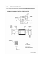
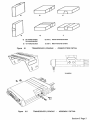
The control board may then be removed from the chassis but it remains connected to the radio PCB
and front panel by a flexible interconnecting circuit-Care must be exercised when re-attaching a
control PCB to the chassis, to ensure that the 5V regulator, IC208, has the insulating washer and
bush correctly fitted. Similarly, when re-attaching the radio PCB
to the chassis, care must be exercised to ensure that the transmitter power amplifier devices have
the correct amount of heatsink compound applied to their mounting faces before fixing to the
chassis.
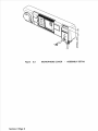
Should the interconnecting flexible printed circuit fail, a hand solderable replacement alternative is
available. The factory fitted flex strip must first be carefully removed from the control PCB, by
applying a "hot air" de-soldering tool to the solder joint and peeling away the soldered connections.
1.4
SALES CODES
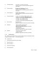
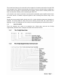
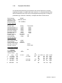
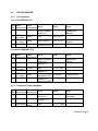
There are, basically, two codes to be described; the 12-digit sales code and the 20-digit
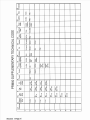
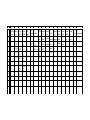
supplementary technical code. A sample of this latter code sheet is included.