1
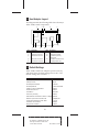
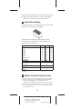
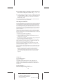
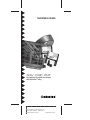
Installation Guide
AHA™-1530P/1532P
Plug and Play AT-to-SCSI Host Adapter
with SCSISelect™ Utility
R
AA
AAAA
AA
AAAAAAAA
AAAAAAAA
AAAAAAAA
AAAAAAAA
AAAAAAAA
AAAAAAAA
AAAAAAAA
AAAAAAAA
AAAAAAAA
AAAAAAAA
AAAAAAAA
AAAAAAAA
AAAAAAA
AA
AHA-1530P/1532P Installation Guide
AA
AA
AA
AA
AA
Part Number: 510484-00, Rev. B
AA
AA
AA
AA
Print
Spec
Number:
492211-00
AA
AA
AA
AA
Current Date: 4/27/94
ECN Date: 5/3/94 AA
AA
AA
AAAAAAAAAAAAAAAAAAAAAAAAAAAAAAAAAAAAAAAAAAAAAAAAAAAAAA
A
Note: Read the AHA-1530P/1532P Getting
Started guide first when you are ready to
install your AHA-1530P/1532P Plug and
Play host adapter. Getting Started explains
Plug and Play technology and tells you how
to make your PC Plug and Play ready before
you install the host adapter.
1 Overview
This Installation Guide explains how to physically
install and configure Adaptec AHA-1530P/1532P
Plug and Play SCSI host adapters. AHA-1530P/
1532P host adapters can be installed in Plug and Play
ready PCs with little or no manual configuration.
The steps needed to make your PC Plug and Play
ready depend on how the PC is configured. Does it
have a Plug and Play BIOS? Are you using an operating system that supports Plug and Play? One of the
steps may be to install the ISA Configuration Utility
(ICU) software included with the host adapter. All
this is explained in Getting Started.
AHA-1530P/1532P host adapters support the SCSI
Configured AutoMagically (SCAM) protocol, which
assigns SCSI IDs dynamically and resolves SCSI ID
conflicts automatically. If your system includes SCSI
disk drives or other peripherals that support SCAM,
you do not need to manually assign SCSI IDs to
these devices.
1
A
AAAA
AAAA
A
AA
AAAA
AAAAAAAA
AAAAAAAA
AAAAAAAA
AAAAAAAA
AAAAAAAA
AAAAAAAA
AAAAAAAA
AAAAAAAA
AAAAAAAA
AAAAAAAA
AAAAAAAA
AAAAAA
A
AA
AHA-1530P/1532P Installation Guide
A
AA
A
AA
A
AA
Part
Number:
510484-00,
Rev.
B
A
AA
A
AA
A
AA
Print
Spec
Number:
492211-00
A
AA
A
AA
A
AA
Current
Date:
4/27/94
ECN
Date:
5/3/94
A
AA
A
AAAAAAAAAAAAAAAAAAAAAAAAAAAAAAAAAAAAAAAAAAAAAAAAAAAAAA
AA
2 Host Adapter Layout
This diagram and the following table show the major
AHA-1530P/1532P components.
J1
U1
U7
J2 DS1
S1
J3
U5
U6
Label
DS1
J1
J2
Description
Termination Indicator
Floppy Drive Connector1
External LED Connector
Label
S1
U1
U5
J3
J4
Internal SCSI Connector
External SCSI Connector
U6
U7
1 AHA-1532P
J4
Description
Switch Block
Floppy Drive Controller1
AIC-3350 Plug and Play
Interface Chip
AIC-6360 SCSI Protocol Chip
Host Adapter BIOS Chip
only.
3 Default Settings
AHA-1530P/1532P host adapters operate correctly
with their factory default settings in most PCs. The
default settings are as follows:
Parameter
Host Adapter SCSI ID
Interrupt Channel
Host Adapter Termination
Host Adapter BIOS
Initiate Synchronous Negotiation
Enable Disconnection
Port Address
SCSI Parity Checking
Extended BIOS Translation for Drives >1 GByte
Maximum Synchronous Transfer Rate
Support Removable Disks under BIOS
Send Start Unit Command
Floppy Drive Controller1
Default Setting
7
IRQ 11
Automatic
Enabled at DC000h
Enabled
Enabled
340h-35Fh
Enabled
Disabled
10 MBytes/sec.
Boot only
Disabled
Enabled
1 AHA-1532P only
2
A
AAAA
AAAA
A
AA
AAAA
AAAAAAAA
AAAAAAAA
AAAAAAAA
AAAAAAAA
AAAAAAAA
AAAAAAAA
AAAAAAAA
AAAAAAAA
AAAAAAAA
AAAAAAAA
AAAAAAAA
AAAAAA
A
AA
AHA-1530P/1532P Installation Guide
A
AA
A
AA
A
AA
Part
Number:
510484-00,
Rev.
B
A
AA
A
AA
A
AA
Print
Spec
Number:
492211-00
A
AA
A
AA
A
AA
Current
Date:
4/27/94
ECN
Date:
5/3/94
A
AA
A
AAAAAAAAAAAAAAAAAAAAAAAAAAAAAAAAAAAAAAAAAAAAAAAAAAAAAA
AA
Plug and Play may override some default settings
when it assigns system resources. Section 6, Configuring the Host Adapter, explains how to change settings with the SCSISelect utility.
4 Installing the Host Adapter
Inserting the Host Adapter
Follow these steps to insert the host adapter in a slot:
WARNING: Turn OFF and disconnect the
power to your PC and attached devices
before you remove the chassis cover. See
your PC’s documentation for instructions.
1 Remove the PC chassis cover to expose the expansion slots and external access covers.
2 Identify an empty expansion slot.
3 Remove the corresponding external access cover
from the rear opening on the PC chassis.
4 Align the bus connector on the bottom of the host
adapter with the slot and carefully insert it into
the slot. Attach the host adapter bracket to the PC
chassis with the expansion slot cover screw.
Note: Do not replace the PC chassis cover or
reconnect the power yet.
Setting Host Adapter Switches
If you need to change host adapter switch settings,
do it now before you replace the chassis cover and
run the SCSISelect utility. (See Section 9, Switch Block
Settings.) Here are some possible reasons for changing the switch settings:
Controlling Floppy Drives (AHA-1532P only)
If you do not want to use the onboard floppy drive
controller on your AHA-1532P host adapter, set sw5
to On to disable it. If you connect the floppy drives to
the AHA-1532P floppy controller you must disable
other floppy controllers in the PC. See your PC
documentation.
3
A
AAAA
AAAA
A
AA
AAAA
AAAAAAAA
AAAAAAAA
AAAAAAAA
AAAAAAAA
AAAAAAAA
AAAAAAAA
AAAAAAAA
AAAAAAAA
AAAAAAAA
AAAAAAAA
AAAAAAAA
AAAAAA
A
AA
AHA-1530P/1532P Installation Guide
A
AA
A
AA
A
AA
Part
Number:
510484-00,
Rev.
B
A
AA
A
AA
A
AA
Print
Spec
Number:
492211-00
A
AA
A
AA
A
AA
Current
Date:
4/27/94
ECN
Date:
5/3/94
A
AA
A
AAAAAAAAAAAAAAAAAAAAAAAAAAAAAAAAAAAAAAAAAAAAAAAAAAAAAA
AA
Disabling the BIOS
The AHA-1530P/1532P onboard BIOS is enabled by
default. This allows you to boot your PC from a SCSI
disk drive connected to the host adapter. It also
allows you to run the SCSISelect utility when your
PC boots, as described in Section 6. However, when
the onboard BIOS is enabled, the host adapter ’s IRQ
and other resources are fixed and cannot be reassigned by Plug and Play, unless the PC motherboard
BIOS supports Plug and Play.
Depending on how your PC is configured, you may
need to change the default host adapter BIOS setting.
This is controlled by switches sw1, sw2, and sw3 on
switch block s1. Getting Started explains the possible
configuration scenarios.
Section 9 of this Installation Guide lists the values of
all the available switch settings.
5 Connecting Peripheral Devices
Assigning SCSI IDs
You can connect up to seven internal and/or external
SCSI devices to your host adapter. Each SCSI disk
drive, CD-ROM drive, or other peripheral device
must have a unique SCSI ID in the range of 0 to 6.
(The host adapter usually has ID 7.)
Some newer SCSI disk drives are SCAM-capable. The
SCAM software included with your host adapter
automatically assigns unique SCSI IDs to SCAMcapable devices when you boot your PC.
Most SCSI peripherals currently in use, however, are
not SCAM-capable. SCSI IDs on these devices are
set with switches or jumpers and cannot be changed
by SCAM commands.
If your SCSI peripherals are not SCAM-capable, you
must be sure that each device is set to a unique SCSI
ID. See your SCSI device documentation for
instructions.
The host adapter SCSI ID can be set in the SCSISelect
utility but may be changed by SCAM. Normally, you
should leave the host adapter SCSI ID at the default
setting of 7.
4
A
AAAA
AAAA
A
AA
AAAA
AAAAAAAA
AAAAAAAA
AAAAAAAA
AAAAAAAA
AAAAAAAA
AAAAAAAA
AAAAAAAA
AAAAAAAA
AAAAAAAA
AAAAAAAA
AAAAAAAA
AAAAAA
A
AA
AHA-1530P/1532P Installation Guide
A
AA
A
AA
A
AA
Part
Number:
510484-00,
Rev.
B
A
AA
A
AA
A
AA
Print
Spec
Number:
492211-00
A
AA
A
AA
A
AA
Current
Date:
4/27/94
ECN
Date:
5/3/94
A
AA
A
AAAAAAAAAAAAAAAAAAAAAAAAAAAAAAAAAAAAAAAAAAAAAAAAAAAAAA
AA
If you need to set SCSI IDs with switches or jumpers,
we recommend that you assign SCSI IDs 0 and 1 to
the first two SCSI hard disk drives.
Terminating SCSI Devices
The SCSI bus is the cabling that connects SCSI
devices to the AHA-1530P/1532P. Data can only be
transmitted on the SCSI bus if the devices at each end
of the bus are terminated. Termination must be disabled on all other devices on the SCSI bus.
Termination on the host adapter itself is controlled
by software commands via the SCSISelect utility. The
default setting is Automatic, which works like this:
■
The host adapter terminates itself if only external
or only internal peripherals are connected to it
(that is, if the host adapter is the last device on the
bus).
■
The host adapter disables its termination if both
internal and external peripherals are connected to
it (that is, if the host adapter is in the middle of
the bus).
You can also change the host adapter termination
setting to Enabled or Disabled. To do this, first complete the physical installation, then run SCSISelect.
(See Section 6, Configuring the Host Adapter.)
Termination Status Indicator
The onboard LED next to the internal SCSI connector
changes color to indicate the SCSI bus termination
status:
■
A green light means that termination is set correctly (two devices are terminated).
■
A red light means that more than two devices are
terminated.
■
An orange light means that fewer than two devices
are terminated.
(The LED lights up only when the disk drive is
active.)
5
A
AAAA
AAAA
A
AA
AAAA
AAAAAAAA
AAAAAAAA
AAAAAAAA
AAAAAAAA
AAAAAAAA
AAAAAAAA
AAAAAAAA
AAAAAAAA
AAAAAAAA
AAAAAAAA
AAAAAAAA
AAAAAA
A
AA
AHA-1530P/1532P Installation Guide
A
AA
A
AA
A
AA
Part
Number:
510484-00,
Rev.
B
A
AA
A
AA
A
AA
Print
Spec
Number:
492211-00
A
AA
A
AA
A
AA
Current
Date:
4/27/94
ECN
Date:
5/3/94
A
AA
A
AAAAAAAAAAAAAAAAAAAAAAAAAAAAAAAAAAAAAAAAAAAAAAAAAAAAAA
AA
Connecting Internal SCSI Peripherals
Caution: AHA-1530P/1532P host adapters
support only single-ended SCSI devices. Do
not connect differential SCSI devices to the
host adapter. Read the device documentation
to determine whether a SCSI device is singleended or differential.
Follow these steps to connect the host adapter to
SCSI devices mounted inside the PC case. Use the
internal SCSI cable included with your host adapter.
1 Disable termination on all internal SCSI devices.
Read the device documentation if you are not
sure how to do this.
2 Plug the 50-pin female connector on one end of
the internal cable into the host adapter’s internal
SCSI connector. (This is the end of the cable that
does not have a terminator attached to it.) Be sure
to match pin 1 on the cable with pin 1 on the host
adapter ’s internal SCSI connector.
Pin 1 is marked with a contrasting color on one
edge of the ribbon cable. A small triangle marks
pin 1 on the host adapter SCSI connector.
3 Plug the next female connector on the cable into
the connector of the closest internal SCSI device.
4 Plug the next female connector on the cable into
the connector of the second internal SCSI device,
if there is one. The terminator on the end of the
internal cable will extend beyond the second
internal device.
If you have more than two internal SCSI devices,
you must get a 50-pin internal cable with enough
connectors for all the devices. Be sure to terminate
the last internal device attached to the cable.
5 If you are using the AHA-1532P onboard floppy
drive controller, connect the 34-pin floppy ribbon
cable to the host adapter’s floppy connector. Be
sure to maintain pin-1 orientation.
6
A
AAAA
AAAA
A
AA
AAAA
AAAAAAAA
AAAAAAAA
AAAAAAAA
AAAAAAAA
AAAAAAAA
AAAAAAAA
AAAAAAAA
AAAAAAAA
AAAAAAAA
AAAAAAAA
AAAAAAAA
AAAAAA
A
AA
AHA-1530P/1532P Installation Guide
A
AA
A
AA
A
AA
Part
Number:
510484-00,
Rev.
B
A
AA
A
AA
A
AA
Print
Spec
Number:
492211-00
A
AA
A
AA
A
AA
Current
Date:
4/27/94
ECN
Date:
5/3/94
A
AA
A
AAAAAAAAAAAAAAAAAAAAAAAAAAAAAAAAAAAAAAAAAAAAAAAAAAAAAA
AA
Connecting External SCSI Peripherals
Follow these steps to connect the host adapter to
SCSI disk drives, CD-ROM drives, and other external
devices.
1 Attach the connector of a 50-pin, high-density
external SCSI cable to the host adapter ’s external
SCSI connector. (External cables can only be
plugged in one way, so pin-1 orientation is
automatic.)
2 Plug the other end of the cable into one of the two
SCSI connectors on the back of the first external
SCSI device.
3a If there is only one external SCSI device, insert a
terminator plug into the device’s other SCSI connector to terminate this end of the SCSI bus, or
3b If you have more than one external device, plug an
external cable into the first device’s other SCSI
connector. Plug the other end of this cable into a
SCSI connector on the next external device. Link
all external devices like this. Insert a terminator
plug into the other SCSI connector on the last
device.
If you have an external device with only one SCSI
connector, place it at the end of the bus and terminate it. (Read the device documentation.)
Reassembling and Starting the PC
Follow these steps to reassemble and power the PC:
1 Replace the PC chassis cover, following the
instructions in your PC’s documentation.
2 Be sure all power switches are OFF, then reconnect
the power cables to your PC.
3 Turn ON the power for the PC and peripheral(s).
Last sentence
deleted from
this paragraph.
At system bootup the host adapter BIOS sign-on
message appears on the monitor (if the BIOS is
enabled). The host adapter finds devices on the SCSI
bus and assigns SCSI IDs to SCAM devices.
7
A
AAAA
AAAA
A
AA
AAAA
AAAAAAAA
AAAAAAAA
AAAAAAAA
AAAAAAAA
AAAAAAAA
AAAAAAAA
AAAAAAAA
AAAAAAAA
AAAAAAAA
AAAAAAAA
AAAAAAAA
AAAAAA
A
AA
AHA-1530P/1532P Installation Guide
A
AA
A
AA
A
AA
Part
Number:
510484-00,
Rev.
B
A
AA
A
AA
A
AA
Print
Spec
Number:
492211-00
A
AA
A
AA
A
AA
Current
Date:
4/27/94
ECN
Date:
5/3/94
A
AA
A
AAAAAAAAAAAAAAAAAAAAAAAAAAAAAAAAAAAAAAAAAAAAAAAAAAAAAA
AA
6 Configuring the Host Adapter
Your host adapter includes the SCSISelect utility,
which lets you change configuration settings without opening your PC or editing configuration files.
Running the SCSISelect Utility
If the AHA-1530P/1532P onboard BIOS is enabled,
you can start the SCSISelect utility by pressing Ctrl-A
when the prompt appears at boot time.
If the AHA-1530P/1532P onboard BIOS is disabled,
you must run an executable version of SCSISelect
called 1530cfg.exe. You can download this file from
the Adaptec BBS. (The BBS phone number is listed
on page 10 of this Installation Guide.)
Use the ↑, ↓, and Enter keys to make selections. Press
Esc to return to the previous menu. Press F6 to
restore the original SCSISelect default values. To
abandon changes made in the Configure/View Host
Adapter Settings menu, press Esc and select No
when asked if you want to save the changes.
SCSISelect Main Menu Options
Configure/View Host Adapter Settings
The Configuration screen displays these options:
Host Adapter Interrupt (IRQ) Channel, Host
Adapter SCSI ID, SCSI Parity Checking, and Host
Adapter SCSI Termination. Highlight an option and
press Enter to see a list of possible values.
Note: If the host adapter BIOS is disabled,
Plug and Play assigns the host adapter’s IRQ
and other resources when you boot the PC.
This may override any IRQ changes you
made in the SCSISelect utility.
Select SCSI Device Configuration to view a menu of
the following options for each device on the SCSI
bus: Initiate Synchronous Negotiation, Maximum
Synchronous Transfer Rate, Enable Disconnect, and
Send Start Unit Command. You can set these options
individually for each device on the SCSI bus.
8
A
AAAA
AAAA
A
AA
AAAA
AAAAAAAA
AAAAAAAA
AAAAAAAA
AAAAAAAA
AAAAAAAA
AAAAAAAA
AAAAAAAA
AAAAAAAA
AAAAAAAA
AAAAAAAA
AAAAAAAA
AAAAAA
A
AA
AHA-1530P/1532P Installation Guide
A
AA
A
AA
A
AA
Part
Number:
510484-00,
Rev.
B
A
AA
A
AA
A
AA
Print
Spec
Number:
492211-00
A
AA
A
AA
A
AA
Current
Date:
4/27/94
ECN
Date:
5/3/94
A
AA
A
AAAAAAAAAAAAAAAAAAAAAAAAAAAAAAAAAAAAAAAAAAAAAAAAAAAAAA
AA
Select Advanced Configuration Options to view a
menu of the following options: Host Adapter BIOS
Enable/Disable, Support Removable Disks under
BIOS as Fixed Disks, and Extended BIOS Translation for DOS Drives > 1 GByte. Do not change these
options unless absolutely necessary.
SCSI Disk Utilities
When you select SCSI Disk Utilities from the Main
Menu, a list of installed SCSI devices appears. When
you select a device, the Utilities menu appears.
Format Disk runs the Adaptec SCSI low-level format utility. Verify Disk Media scans the selected
device's media for defects. If it finds bad blocks, it
prompts you to reassign them.
7 I/O Operating Environment Software
DOS/Windows
You can connect up to two SCSI hard disk drives to
the AHA-1530P/1532P without installing additional
software. Adaptec EZ-SCSI™ provides the additional
software you need if you want to
■
Install more than two SCSI hard disk drives
■
Install CD-ROM drives
■
Remove and insert CD-ROMs and other removable media while your PC is running
■
Use a scanner or a SCSI tape drive
To order EZ-SCSI and other Adaptec software products, call the Adaptec software and cables telephone
number listed on page 10 of this Installation Guide.
Other Operating Environments
Contact Adaptec or your operating system vendor
for information on the availability of AHA-1530P/
1532P drivers for other operating environments.
8 Troubleshooting Checklist
Do this if you have a problem during installation:
■
Make sure all SCSI cables and power cables are
properly connected and all devices are powered.
9
A
AAAA
AAAA
A
AA
AAAA
AAAAAAAA
AAAAAAAA
AAAAAAAA
AAAAAAAA
AAAAAAAA
AAAAAAAA
AAAAAAAA
AAAAAAAA
AAAAAAAA
AAAAAAAA
AAAAAAAA
AAAAAA
A
AA
AHA-1530P/1532P Installation Guide
A
AA
A
AA
A
AA
Part
Number:
510484-00,
Rev.
B
A
AA
A
AA
A
AA
Print
Spec
Number:
492211-00
A
AA
A
AA
A
AA
Current
Date:
4/27/94
ECN
Date:
5/3/94
A
AA
A
AAAAAAAAAAAAAAAAAAAAAAAAAAAAAAAAAAAAAAAAAAAAAAAAAAAAAA
AA
■
Make sure all SCSI devices have unique SCSI IDs.
■
Make sure the SCSI bus is correctly terminated.
(See Section 5, Connecting SCSI Peripherals.)
9 Switch Block Settings
The five switches on switch block s1 are all set to Off
by default, as shown in this diagram:
5
4
3
1
2
OF
F
This table shows all the possible settings of the
switches on switch block s1. Default settings are
marked with an asterisk (*).
BIOS Address
DC000h*
D8000h
D4000h
D0000h
CC000h
C8000h
DC000h, Inactive
BIOS Disable
Port Address
340h to 35Fh*
140h to 15Fh
Floppy Controller (AHA-1532P only)
Enabled*
Disabled
sw1
Off
On
Off
On
Off
On
Off
On
sw2
Off
Off
On
On
Off
Off
On
On
sw4
Off
On
sw5
Off
On
sw3
Off
Off
Off
Off
On
On
On
On
Off = Open
10 Adaptec Customer Support Services
■
For information on software upgrades, new releases, technical
advice, and other topics, call the Adaptec Electronic Bulletin
Board Service (BBS) 24 hours a day at 408-945-7727;
1200/2400/9600/14400 baud, 8 data bits, 1 stop bit, no parity.
■
For the latest online information about Adaptec products and
services, call the Interactive Fax Service 23 hours a day, 7 days a
week, at 408-957-7150.
10
A
AAAA
AAAA
A
AA
AAAA
AAAAAAAA
AAAAAAAA
AAAAAAAA
AAAAAAAA
AAAAAAAA
AAAAAAAA
AAAAAAAA
AAAAAAAA
AAAAAAAA
AAAAAAAA
AAAAAAAA
AAAAAA
A
AA
AHA-1530P/1532P Installation Guide
A
AA
A
AA
A
AA
Part
Number:
510484-00,
Rev.
B
A
AA
A
AA
A
AA
Print
Spec
Number:
492211-00
A
AA
A
AA
A
AA
Current
Date:
4/27/94
ECN
Date:
5/3/94
A
AA
A
AAAAAAAAAAAAAAAAAAAAAAAAAAAAAAAAAAAAAAAAAAAAAAAAAAAAAA
AA
■
For technical assistance, call Adaptec’s Technical Support Hot
Line at 800-959-SCSI (7274), or 408-945-2550.
M–Th: 6:00 a.m.–5:00 p.m., F: 6:00 a.m.–3:00 p.m., Pacific Time.
■
To order Adaptec software and cables, call 800-442-SCSI (7274)
or 818-365-6264. M–F: 6:00 a.m.–5:00 p.m., Pacific Time. If you
are calling from outside the U.S. and Canada, the number is
408-957-SCSI (7274).
■
To request literature on Adaptec products, call 800-934-2766.
M–F: 5:00 a.m.–6:00 p.m., Pacific Time.
FCC Compliance Statement
NOTE: This equipment has been tested and found to comply with the limits
for a Class B digital device, pursuant to Part 15 of the FCC rules. These limits are designed to provide reasonable protection against harmful interference in residential installations. This equipment generates, uses, and can
radiate radio frequency energy, and if not installed and used in accordance
with the instructions, may cause harmful interference to radio communications. However, there is no guarantee that interference will not occur in a
particular installation.
If this equipment does cause interference to radio or television equipment
reception, which can be determined by turning the equipment off and on,
the user is encouraged to try to correct the interference by one or more of the
following measures:
•
•
•
Reorient or relocate the receiving antenna
Move the equipment away from the receiver
Plug the equipment into an outlet on a circuit different from that to
which the receiver is powered
• If necessary, the user should consult the dealer or an experienced radio/
television technician for additional suggestions
CAUTION: Only equipment certified to comply with Class B (computer
input/output devices, terminals, printers, etc.) should be attached to this
equipment, and must have shielded interface cables.
Finally, any change or modifications to the equipment by the user not
expressly approved by the grantee or manufacturer could void the user's
authority to operate such equipment.
Each AHA-1530P/1532P is equipped with an FCC compliance label which
shows only the FCC Identification number. The full text of the associated
label follows:
This device complies with part 15 of the FCC rules. Operation is
subject to the following two conditions: (1) this device may not
cause harmful interference and (2) this device must accept any interference received, including interference that may cause undesired
operation.
Adaptec, Inc.
691 South Milpitas Blvd.
Milpitas, CA 95035
Copyright © 1993, 1994, Adaptec, Inc. All rights reserved.
Adaptec and the Adaptec logo are registered trademarks of
Adaptec, Inc. AHA, EZ-SCSI, and SCSISelect are trademarks of
Adaptec, Inc.
Printed in Singapore
Stock No.: 510484-00, Rev. B KL 5/94
Information subject to change without notice.
11
A
AAAA
AAAA
A
AA
AAAA
AAAAAAAA
AAAAAAAA
AAAAAAAA
AAAAAAAA
AAAAAAAA
AAAAAAAA
AAAAAAAA
AAAAAAAA
AAAAAAAA
AAAAAAAA
AAAAAAAA
AAAAAA
A
AA
AHA-1530P/1532P Installation Guide
A
AA
A
AA
A
AA
Part
Number:
510484-00,
Rev.
B
A
AA
A
AA
A
AA
Print
Spec
Number:
492211-00
A
AA
A
AA
A
AA
Current
Date:
4/27/94
ECN
Date:
5/3/94
A
AA
A
AAAAAAAAAAAAAAAAAAAAAAAAAAAAAAAAAAAAAAAAAAAAAAAAAAAAAA
AA