1
A Network Measurement System for Wide Area Networks
Matei Ciobotaru, C˘at˘alin Meiro¸su, Miron Brezuleanu, Mihai Ivanovici
January 15, 2003
Contents
1 Introduction
3
2 Network Performance Measurements Systems
4
2.1
2.2
2.3
Network testers . . . . . . . . . . . . . . . . . . . . . . . . . . . . . . . . . .
4
2.1.1
IXIA IxCore . . . . . . . . . . . . . . . . . . . . . . . . . . . . . . .
4
2.1.2
Brix 2500 Verifier . . . . . . . . . . . . . . . . . . . . . . . . . . . . .
4
2.1.3
Spirent Adtech AX/4000 . . . . . . . . . . . . . . . . . . . . . . . .
5
2.1.4
Surveyor and RIPE
. . . . . . . . . . . . . . . . . . . . . . . . . . .
5
Synchronization for long distance measurements . . . . . . . . . . . . . . . .
6
2.2.1
The Network Time Protocol . . . . . . . . . . . . . . . . . . . . . . .
6
2.2.2
Network Time Servers . . . . . . . . . . . . . . . . . . . . . . . . . .
7
2.2.3
GPS Receivers . . . . . . . . . . . . . . . . . . . . . . . . . . . . . .
8
2.2.4
Sample implementations . . . . . . . . . . . . . . . . . . . . . . . . .
9
Some observations . . . . . . . . . . . . . . . . . . . . . . . . . . . . . . . .
10
3 System Architecture
11
3.1
General overview . . . . . . . . . . . . . . . . . . . . . . . . . . . . . . . . .
11
3.2
Testing Wide Area Networks . . . . . . . . . . . . . . . . . . . . . . . . . .
13
3.3
Generating IP packets . . . . . . . . . . . . . . . . . . . . . . . . . . . . . .
14
3.4
The global clock system . . . . . . . . . . . . . . . . . . . . . . . . . . . . .
14
4 The GPS-based Clock Synchronization System
16
4.1
Resources that are used . . . . . . . . . . . . . . . . . . . . . . . . . . . . .
16
4.2
Description of the method . . . . . . . . . . . . . . . . . . . . . . . . . . . .
17
4.3
Testing the method . . . . . . . . . . . . . . . . . . . . . . . . . . . . . . . .
19
1
CONTENTS
5 Traffic Generation
5.1
Traffic profiles . . . . . . . . . . . . . . . . . . . . . . . . . . . . . . . . . . .
2
20
20
6 Measurements and Results
24
7 Conclusions and Future Work
26
A Installation
28
A.1 Technical requirements . . . . . . . . . . . . . . . . . . . . . . . . . . . . . .
28
A.2 Hardware . . . . . . . . . . . . . . . . . . . . . . . . . . . . . . . . . . . . .
28
A.3 Cable connections . . . . . . . . . . . . . . . . . . . . . . . . . . . . . . . .
29
A.4 Software . . . . . . . . . . . . . . . . . . . . . . . . . . . . . . . . . . . . . .
29
A.4.1 The GPS card driver . . . . . . . . . . . . . . . . . . . . . . . . . . .
30
A.4.2 The clock card kernel module . . . . . . . . . . . . . . . . . . . . . .
30
A.4.3 The manager program – HS MASTER . . . . . . . . . . . . . . . . .
31
A.4.4 Using the hs master . . . . . . . . . . . . . . . . . . . . . . . . . . .
32
B Implementation details
33
B.1 Clock boards . . . . . . . . . . . . . . . . . . . . . . . . . . . . . . . . . . .
33
B.1.1 Hardware . . . . . . . . . . . . . . . . . . . . . . . . . . . . . . . . .
33
B.1.2 Software and Firmware . . . . . . . . . . . . . . . . . . . . . . . . .
35
B.2 GPS cards . . . . . . . . . . . . . . . . . . . . . . . . . . . . . . . . . . . . .
35
B.3 Manager software . . . . . . . . . . . . . . . . . . . . . . . . . . . . . . . . .
36
C Results obtained during development
37
C.1 Testing the GPS card . . . . . . . . . . . . . . . . . . . . . . . . . . . . . .
37
C.2 Local synchronization test . . . . . . . . . . . . . . . . . . . . . . . . . . . .
37
C.3 Global synchronization test . . . . . . . . . . . . . . . . . . . . . . . . . . .
38
D GPS Synchronization HOW-TO
40
E Troubleshooting synchronization problems
42
Chapter 1
Introduction
In this report we present a system for measuring the performance of wide area computer
networks. The system is used to test network devices (switches, routers) and various network topologies that will be part of the ATLAS experiment at CERN.
This experiment (at the CERN Large Hadron Collider) will generate a huge amount of data
that will have to be processed and filtered in real time. There are proposals to distribute
the necessary computing power in different remote locations that will be connected by
high speed networks. In order to transfer the data generated by the experiment, very high
performance networking will be needed – speeds of the order of Gigabit/sec will be common.
We want to measure different parameters of high speed networks and estimate the impact
of their performance on the data processing system.
The most important measurements that are needed are the one-way transfer latency, the
throughput and the packet loss. We want to stress here that the one-way latency, as opposed
to half of the Round Trip Time (RTT), is important because the routing over the Internet is
not symmetric – a data stream between two points can travel on one route in one direction
and on a completely different route in the opposite direction.
The method of performing this type of latency measurement will be presented in detail in
this report. We shall see that it requires synchronized clocks in remote locations and we’ll
show how this is obtained using the Global Positioning System.
The following section will present several testing systems or architectures that are available
on the market. We shall speak also about the difficulties that appear in long distance
measurements.
3
Chapter 2
Network Performance
Measurements Systems
Network testers are devices that can perform measurements of various network parameters.
Usually they are deployed in key points of a network and they work in a distributed fashion.
They perform measurements by injecting traffic into one end of the network and capturing
it at the other end. Using special data embedded in the traffic streams, they are able to
determine one-way latencies, packet loss, jitter or throughput. There are testers that can do
Quality of Service measurements for Voice over IP, or that can emulate certain applications
to see how they behave over a certain network.
We are interested in a system that can perform accurate measurements over the Internet.
The system should be very flexible and the user should be able to extend it if new functionality is needed. Also a high performance system is needed to analyze networks running
at Gigabit speeds.
2.1
2.1.1
Network testers
IXIA IxCore
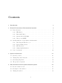
The IxCore is a network performance monitoring system. It is a distributed system consisting of collocated measuring devices called Ixia 100s, which are time synchronized across the
globe using the Global Positioning System (GPS) or the CDMA cellular system. IxCore
includes centralized, web-based reporting and management and provides real-time monitoring of critical network performance metrics such as one-way latency, packet loss and jitter.
The accuracy of latency measurements is at the order of microsecond. The system provides
historical reports and an SQL database with the measurements.
2.1.2
Brix 2500 Verifier
The Brix System consists of a family of purpose-built hardware appliances: including the
Brix 100 Verifier, Brix 1000 Verifier, and Brix 2500 Verifier – that are deployed pervasively
throughout a network and are tightly coupled with a carrier-class, central site software
4
CHAPTER 2. NETWORK PERFORMANCE MEASUREMENTS SYSTEMS
5
Figure 2.1: The IXIA IxCore Network Tester
system, BrixWorx. The Brix 2500 Verifier calculates fundamental network performance
statistics (such as one-way packet latency, jitter and packet loss) and application responsiveness (such as Web page download and call setup time) by measuring high-level application transactions. Timing measurements use the Brix 2500 Verifier’s hardware time
stamp engine and a GPS module, which can provide worldwide, accurate synchronization
to sub-100 microsecond precision, allowing Gigabit speed measurements.
2.1.3
Spirent Adtech AX/4000
The AX/4000 is a system for testing IP Performance and Quality of Service. AX/4000
Test Modules generate and analyze Layer 3 IP traffic at speeds up to 10 Gbps, while
software options enable sophisticated protocol emulation and decoding, control and data
plane testing, routing and MPLS emulation, and more. The real-time traffic generation
supports multiple traffic sources, traffic distribution models, packet length distributions,
class of service traffic prioritization and error injection in the data streams. The system
offers traffic filters, histograms and charts and protocol decoding. AX/4000 is a modular
multi-port system capable of testing multiple transmission technologies such as ATM, IP,
Frame Relay and Ethernet simultaneously at speeds up to 10 Gbps. It is built with FPGAs
and it offers a C/TCL function library for writing scripts. It also supports GPS timing
with an accuracy of 1us for one-way latency measurements.
2.1.4
Surveyor and RIPE
Surveyor and RIPE are systems that make one-way delay measurements over the Internet
and require a Global Positioning System (GPS) to provide clock synchronization between
sites. Both of these tools make end-to-end active performance measurements of the Internet.
They rely on a dedicated PC running Unix to be placed at each monitoring site. Each PC
in turn relies on a Global Positioning System (GPS) device to obtain accurate time and
to synchronize time between each of the monitors. The monitors send packets at Poisson
randomized time intervals to each other and use these packets to gather one way end-toend delay and loss measurements. They also make concurrent traceroutes which provide
route history information. Each box (monitoring agent) has its own GPS receiver so the
CHAPTER 2. NETWORK PERFORMANCE MEASUREMENTS SYSTEMS
6
accuracy of the measurements is good (around 10us) but depends on the operating system.
The traffic generated is for 10/100Mbps links.
2.2
Synchronization for long distance measurements
Time synchronization is a critical piece of infrastructure for any distributed system. In the
case of network research, we need synchronized clocks in order to accurately measure delays
in a distributed network that may span over a wide geographical area.
Our goal is to do one-way network measurements on a network with nodes which are
geographically far apart. This requires synchronized clocks on all the nodes involved in
the measurements. The maximum difference between two clocks should be less than 1
microsecond. This precision is needed for running tests over Gigabit Ethernet links.
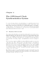
The delay between end nodes is measured in the following way: each packet generated by
a node is marked with a time stamp (value of a clock counter) by the sending node and
with another time stamp when it arrives at the destination node. In order to measure the
delay caused by the network we must make the difference between these two time stamps.
For this result to be meaningful we must have the clocks in the two end nodes perfectly
synchronized (Figure 2.2).
time = t1
time = t2
one way delay = t2 − t1
Figure 2.2: Measuring one way delay between two end nodes
In the following we shall present the clock synchronization methods that are available on the
market today. Expected performance is discussed. Most of the methods involve network
time transfer protocols that provide accuracies of the order of 1-10 milliseconds. When
used with GPS and direct connection time transfer techniques they can provide accuracies
of the order of 1-10 microseconds.
2.2.1
The Network Time Protocol
The most common method of synchronizing computer clocks in a network is based on the
Network Time Protocol. This protocol is designed to distribute accurate and reliable time
information to systems operating in diverse and widely distributed inter-networked environments. The system is based on a network of time servers operating in a self-organizing,
CHAPTER 2. NETWORK PERFORMANCE MEASUREMENTS SYSTEMS
7
hierarchical configuration where clocks are synchronized to each other and to world-wide
time standards (UTC time).
There is a hierarchy of NTP time servers, depending on the accuracy of their time references
(from stratum 0 – atomic clocks, up to stratum 15). NTP operates in a client/server fashion.
The client queries periodically the time server and it dynamically adjusts its clock to match
the one from the server. Due to unpredictable network delays that can’t be easily modeled
and due to the timing hardware found in common computers, in most cases the accuracy
of NTP synchronized clocks is of the order of milliseconds. However this can be improved
in certain conditions.
For the Unix operating systems there are kernel modifications — nanokernel patches —
that can improve the resolution of computer clocks to the order of nanoseconds. The goal
is to offer a function for reading time with the resolution up to a nanosecond. The principle
is to use the Process Cycle Counter found in modern processors – this counts CPU ticks,
at the frequency of the CPU. Therefore, the resolution is dependent on the CPU clock and
it is really at the order of 1 nanosecond with modern processors. There are three issues
concerning this system:
• The clock can’t be easily controlled or reseted on request
• There might appear indeterminations in the time-stamping process because of the
way the clock is read
• It does not work very well on multiprocessor systems
The accuracy can be greatly improved if NTP is used together with a very accurate PPS
signal (Pulse per Second) that comes from a GPS receiver or cesium oscillator. The NTP
client can use these pulses to adjust the clocks with much better precision. In this way one
can reach an accuracy of the order of microseconds. See Section 2.2.4 for more information.
2.2.2
Network Time Servers
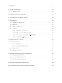
An NTP time server can be a normal workstation running NTP server software and that
is connected to a primary time reference (other time server or a GPS receiver). There are
companies offering network appliances that are dedicated time servers. Some of them are
presented below:
• TymServe 2100, Trusted Time SyncServer S100, Epsilon clock NTP, Lantronix CoBox
NTP
Figure 2.3: A network time server
The common features found in these time servers are:
CHAPTER 2. NETWORK PERFORMANCE MEASUREMENTS SYSTEMS
8
• Accuracy of 10ms on the client side
• Require external time reference (GPS receiver, dial-up, CDMA digital receiver)
• One or more 1Hz PPS and 10MHz outputs redistributed from the GPS
• Compatible with NTP v2,v3 or v4 (with asymmetric encryption)
• Multiple network interfaces
• High quality internal oscillator in case of failure of primary time reference
• Rack-Mountable Unit
As you can see all of these devices need some sort of external time reference. Using a
GPS receiver or some other kind of source, they can provide accurate time to a network of
computers. The accuracy obtained in the default setup is around 10ms.
2.2.3
GPS Receivers
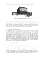
There are many GPS receivers on the market, most of them having the features needed for
network time synchronization. The most important features are a good precision and the
availability of the PPS signal that is used by most procedures. The receiver should also
provide the full time information on request. Some receivers are presented below:
• Motorola Oncore, Trimble Acutime, Jupiter-T, TAC-2 kit, Meinberg GPS PCI Card
Figure 2.4: Sample GPS receiver
The common features are:
• Very accurate (100ns) 1Hz PPS outputs (100PPS for Motorola Oncore)
• Monitoring software (some of them have LCD displays)
• Multiple simultaneous channels
• NMEA Ascii outputs (with the full UTC time information)
• Acquisition time (initial synchronization time): 5 - 20 minutes (cold boot, no data
known)
CHAPTER 2. NETWORK PERFORMANCE MEASUREMENTS SYSTEMS
9
• Some of them can be plugged directly into a computer (Meinberg PCI card)
Instead of a GPS receiver, one can use a CDMA receiver. The main advantage over GPS is
that it does not need a roof-mounted antenna because CDMA signals can be received inside
buildings. The system uses the CDMA cellular mobile communications network which, for
time and frequency applications, acts as a GPS repeater. The accuracy that can be obtained
is around 10 microseconds. One such system is the Praecis Ct from EndRun Technologies.
This device can provide the PPS output and can emulate a GPS receiver so it can be used
in conjunction with NTP (in places where a GPS antenna cannot be installed).
2.2.4
Sample implementations
In the next paragraphs we present two systems that use clock synchronization mechanisms:
one is for network measurements and the other is for accurate time-stamping of events.
High precision solution using NTP and GPS
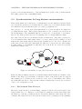
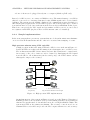
A high precision architecture using NTP and a GPS receiver is shown in Figure 2.5.
It uses an NTP server that reads the timing from a Stratum 0 source - a GPS receiver.
The workstations run NTP client software and a modified Unix kernel – a nanokernel.
An accuracy of the order of microsecond is obtained by distributing the PPS signal
from the GPS to all workstations (via the serial ports) - the NTP software can use
this signal to improve the accuracy.
Network Time Server
GPS Receiver
GPS PPS Signal
NTP via Ethernet
10 miliseconds accuracy
using NTP only
1 − 10 microseconds accuracy
using NTP and the GPS Pulse Per Second signal
Figure 2.5: High precision NTP implementation
An implementation of the setup from Figure 2.5 was done at the Tampere University of
Finland [9] where some researchers developed a measuring system for QoS parameters
that involves synchronized clocks and that can work over Gigabit Ethernet links. The
system uses NTP as the primary mechanism. The accuracy comes from a low-cost
Garmin GPS receiver that can provide the PPS output with microsecond accuracy.
CHAPTER 2. NETWORK PERFORMANCE MEASUREMENTS SYSTEMS
10
The computers involved in the system run a Linux with the nanokernel patches. This
allows a nanosecond resolution of the system clock. The PPS signal is distributed
from the GPS to the serial ports of all computers via standard Cat5 cabling. The
PPS distribution contains also a voltage level converter from TTL to RS-232. The
precision obtained with this setup is of 10 microseconds.
The time synchronization system for K2K experiment
The K2K is a physics experiment developed at the Japanese national high energy
physics laboratory [10]. The experiment needs synchronized clocks in two sites that
are at a distance of 250km one from the other. The solution involved GPS receivers
at each site and some custom made local clock boards (LTC). The clock boards have
a 50MHz free-running counter. The GPS has two outputs: the PPS signal whose
leading edge is correlated with the UTC second, and an Ascii stream with the full
GPS data (time and position). The PPS signal is used to calibrate the clock board
(to see the average number of clock ticks per UTC second).
Upon receipt of each event that needs a time stamp, the LTC count and the GPS
Ascii data are latched and recorded. The LTC count provides the fractional second
of the time, down to 20 nsec precision, accurately synchronized with UTC within
100 nsec. The Ascii data provides the date and coarse time down to seconds. The
accuracy that is obtained is of the order of hundreds of nanoseconds.
2.3
Some observations
Most commercial testers that were presented are dedicated devices that offer a set of services
but that can’t be easily modified by the user without the help of the manufacturer. We
are interested in a system that is powerful enough but still gives full access to its internal
functioning. All the systems described above provide similar functionality for network
testing.
For accurate long distance measurements the solution is the GPS for time synchronization.
If one wants to build a testing system using off-the-shelf PCs and network cards the solution
for accurate timing is the NTP. This protocol can transfer time from host workstations configured as a time server or from off-the-shelf time server products. These network transfer
techniques offer performance in the 1-10 millisecond synchronization accuracy range. This
performance can be extended further, to the 1-10 microsecond range, by employing direct
connection time transfer techniques: time code, serial time messaging, and 1 PPS/reference
frequency signals. The time resolution on the host computers can be also improved up to
the nanosecond level by using some internal registers found in modern processors. The
accuracy obtained is of the order of tens of microseconds.
The most accurate method is the one that uses directly a GPS reference and special clock
cards (as in the K2K experiment) — this is very similar to the method that will be described
in this report.
In the following we shall describe the architecture of the testing system – we shall see
that the most important parts use customized hardware. This is because a pure software
solution cannot handle the performance measurements at full Gigabit line speeds.
Chapter 3
System Architecture
3.1
General overview
The network tester that we use can generate Gigabit Ethernet traffic and can measure all
the important performance parameters of a network. The functionality is similar to other
products that can be found on the market, but our main advantage is the high degree
of flexibility and accuracy. The system uses mainly off-the-shelf hardware and custom
associated software.
The main hardware components are the Alteon Acenic Gigabit Ethernet network interface
cards. These network interfaces can be programmed by the user and their firmware can
be easily changed to suit any particular application or purpose (the source code of the
original firmware was freely available from the manufacturer) — so they give the possibility
to create a flexible network traffic generator and measurement tool.
The cards contain two programmable MIPS compatible processors, some Random Access
Memory and a PCI interface to the host computer. We have modified the code supplied by
the vendor in order to utilize the NIC as a tester. The cards were programmed to generate
frames (at layer 2) according to a pre-defined pattern up to Gigabit Ethernet line speed
for all packet sizes. For latency computation all outgoing packets are marked with a time
stamp from a global clock card (which was designed and built at CERN). The software
running on the network cards is written in C and compiled with tools adapted from the
GNU C compiler (gcc).
All the operations involving the real-time traffic (sending and receiving) are done by the
two CPUs on the card. This avoids the delays related to PCI transfers and allows the
system to generate traffic at full Gigabit line speed, even when multiple NICs are installed
in the same computer.
Prior to starting any tests, each card receives a traffic description table containing the full
header information of the packets to be generated, the size of the packets and the time
between two consecutively sent packets. We thus have full control over all the fields in the
headers (including the Priority from the VLAN field of the Ethernet packet). For the time
between consecutive packets and for all other fields of the packets the user can choose a fixed
value or any other random number distribution. After the traffic descriptors are loaded and
the test started, the host computer in not involved anymore in the traffic generation.
11
CHAPTER 3. SYSTEM ARCHITECTURE
12
The network cards have internal clocks which are synchronized with the global clock cards.
These clock cards are interconnected with wires and are always synchronized between them.
All the outgoing packets are marked with timestamps (values of the clock counter) and with
sequence numbers (for packet loss calculation).
The NIC receiving traffic uses the timestamps and its global clock reference to determine
the latencies of the incoming packets. The on-board processor builds a histogram with
the latency distribution. The histogram is transferred to the PC’s host processor after
completion of tests (to avoid the possible bottleneck on PCI communication with the host
computer).
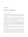
The user interface of the tester is programmed in a client-server manner. One client (a
GUI called the Steering) talks to several servers (the Agents) over an asynchronous socket
connection. The Agent software is installed on the computers hosting the NICs and it
controls their operation. One agent can control multiple cards from the same computer.
The Agent must be running prior to any attempt to be contacted by the Steering.
One−way latency
Packet loss
Throughput
Histograms
Manager
Device Under Test
Agents
Agents
Figure 3.1: The Gigabit Network Tester in a Local Area Network
The main software components of the tester are listed below:
Kernel modules - They enable the access to the Linux devices created for the underlying
hardware components.
Network card firmware - Runs on the Alteon Acenic GE NIC, sending and receiving
traffic according to traffic descriptors uploaded from the host computer
The Agents - Server software component that runs on the computer hosting the NICs; it
transmits the commands and reads the results from the test in real time
The Steering - GUI that controls the operation of the testbed, allowing the user to define
the test, run it and save the results
Traffic generator programs - They generate the array of packet descriptors describing
the traffic that has to be sent by each NIC in the testbed
CHAPTER 3. SYSTEM ARCHITECTURE
13
This measurement system is currently used (with up to 32 Gigabit Ethernet ports) to
characterize switches and LANs for the ATLAS Data Collection. The parameters that can
be measured are throughput, one-way latency and packet loss.
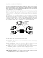
3.2
Testing Wide Area Networks
Initially the tester was designed to run on a Local Area Network (LAN) with all the agents
placed nearby and being interconnected by switches, but then we had to extend it to a
Wide Area Network (Internet). In a LAN setup we only have to deal with Ethernet traffic,
but for the Internet we have the IP layer and some other issues to consider.
The basic requirements for a network performance measuring system that is able to characterize connections over the Internet are:
• to compute throughput and packet loss, taking into account the fact that packets may
be re-ordered
• to compute one-way latency
One−way latency
Packet loss
Throughput
Histograms
Manager
Agent
Agent
Network Under Test
Figure 3.2: The network tester in a WAN environment
The one-way latency is important because the path through the Internet between two endpoints may go through different routers for the two directions. The best approach would
be to compute this value for each and every packet being sent. The exact value of the jitter
on a particular connection for any time interval and traffic pattern can thus be obtained.
To adapt our LAN-geared network performance measuring system to an Internet environment we had to add the following improvements:
• Generate and receive IP packets
• Take into account arrival of out-of-order packets in the packet loss calculation
• Develop a completely new global clock system able to synchronize traffic generators
located at distances of hundreds of kilometers (for one-way latency computation)
CHAPTER 3. SYSTEM ARCHITECTURE
3.3
14
Generating IP packets
We have modified the firmware on the network cards in order to be able to generate IP
packets instead of just simple Ethernet frames. The traffic descriptor table that is loaded
into the card before a test contains all the fields in the IP header, including the IP Type of
Service.
The TCP and UDP were not implemented due to the increased overhead associated with
these protocols. UDP requires the computation of a control sum on the data being transmitted and this would be too time consuming for the processor on-board the NIC to generate
packets at line speed. TCP requires the maintaining of a full history (within the sliding window) of packets being transmitted and received and the on-board memory is limited to 1MB
by the type of chips used by the manufacturer. Also, TCP would be too computationally
intensive to achieve Gigabit speeds on the current on-board processors.
Our traffic generator produces streaming traffic at the raw IP level. The content of the
packets can be considered as being random. The packet loss is calculated by using a
sequence number embedded in the packets.
3.4
The global clock system
The standard way of making network delay (latency) measurements is to calculate the
round-trip time and divide by two in order to obtain the one-way travel time. This method
has the advantage that the same clock is used for both of the send and receive timestamps
and the only important issue is how accurate this clock can be read. However, such a
calculation is only valid when the packet returns on the same route (which is not guaranteed
for an Internet environment).
Computing the one-way network latency provides an accurate estimate of the network’s
behavior under any traffic pattern, especially over long haul networks. In order to make
this calculation, the two timestamps have to be applied by two clocks that are very well
synchronized. Synchronizing two clocks with a sub-microsecond precision is not an easy
task, even when the two clocks are located in the same room. The problem is even more
difficult when a distance of a few hundreds kilometers separates the two clocks. Applying
the timestamps to every packets being sent and received at Gigabit speeds adds a further
degree of difficulty to the problem.
The synchronized clock of our LAN measurement system is based on custom-built boards
and electrical connections between a master and slave boards installed in all the computers
being part of the testbed. The accuracy of the clock board combined with the time-stamping
by the Alteon card when a packet is being sent and received is about 300 ns [2].
The approach of physically connecting the master and slave clock boards is no longer valid
when two parts of the testbed are geographically separated. To overcome this limitation
we are using the Global Positioning System (GPS) to provide a time reference. The GPS
signal is freely available everywhere on Earth and a receiver unit that has enough satellites
in view it is able to give the Universal Time with accuracy in the order of 100 ns [6]. We
are using off-the-shelf GPS receivers connected on the PCI bus of the computer. Only
one computer at each location of the testbed needs to be equipped with such a card and
connected to the special antenna. The GPS card replaces the master clock card from the
CHAPTER 3. SYSTEM ARCHITECTURE
15
previous system. Each computer hosting traffic generator NICs requires a slave clock card.
Typically tens of traffic generators can be accommodated in one system to generate tens of
gigabits of traffic. Each packet can be accurately timestamped.
In the following section we shall present in more detail this clock synchronization system.
Chapter 4
The GPS-based Clock
Synchronization System
To overcome the issues related to the synchronization of geographically separated nodes
we decided to use the Global Positioning System (GPS) to provide a time reference. The
method that is proposed uses custom made clock boards and GPS cards to do the synchronization. The computers part of the testbed are organized in sites that use a local method
of synchronization — all computers in a site are interconnected with wires that transmit
the timing information. To synchronize two remote sites we use a global synchronization
method that uses the GPS as a reference of time.
4.1
Resources that are used
We are using off-the-shelf GPS receivers with the satellite signal received via the exterior
aerials and connected to the PCI bus of the computer. The current implementation uses
Meinberg GPS167PCI cards. The card has a 9-pin connector that provides two important
outputs: one is a 10MHz clock signal and the other is PPS signal (Pulse-Per-Second) issued
at every change of the UTC second with accuracy of 250 nanoseconds. The GPS can also
provide the time to the hosting computer – the minimum time between two readings is of
1.5ms.
The clock cards are designed at CERN and contain an FPGA programmed to run a 32 bit
counter (the clock). These counters are used by the traffic generators to time-stamp the
packets and measure latency. Normally the counter runs according to an external clock
signal, but it can be reseted on request. Currently the frequency of the counter is 40MHz
and is derived from the GPS clock signal (the 10MHz frequency from the GPS is multiplied
by 4 in hardware and we obtain a frequency of 40MHz). At each site we have one master
clock card and several slave clock cards — the master card can send commands to the slaves
to trigger a reset of the counters.
The software is composed of two kernel modules (one for the clock card and one for the
GPS) and some manager programs. The manager is installed on the master computer in
each site and the other computers in a site run a program that accepts commands from the
site manager and that controls the clock cards.
16
CHAPTER 4. THE GPS-BASED CLOCK SYNCHRONIZATION SYSTEM
4.2
17
Description of the method
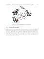
At each site of the testbed we use one GPS card and several clock cards (one for each
computer). The two signals from the GPS (10MHz and PPS) are distributed to all clock
cards. The slave clock cards are forced to count at the same rate by using the 10MHz
output from the GPS clock card — in this way they are automatically synchronized. The
setup inside a site is presented in Figure 4.1
GPS Card
Master Clock
Card
Wire for commands from the master card
10 MHz and 1Hz PPS signal from GPS
Slave Clock
Card
Slave Clock
Card
Slave Clock
Card
Figure 4.1: Local synchronization in a testbed site
Our global clock synchronization system is based on two key points:
• the ability to reset the counters of all the slave clock cards at the same time
• the ability to force the slave clock cards to count at exactly the same rate
Resetting the counters at the same time is accomplished with the help of the GPS card
and 1Hz PPS signal. This signal is issued by the card with an accuracy of 250 ns with
respect to the UTC second. The 1 Hz signal is connected directly to all clock cards in a
site. When a counter reset is required, the slave clock cards are put in a special listening
mode by software. In this mode, the cards are waiting for the next 1 Hz pulse to reset its
counter — when the first pulse comes, all the cards on the site reset their counter to zero.
Because the PPS signal is triggered by the UTC second, it means that it will arrive in the
same time in two remote sites that use different GPS cards. In this way we synchronize all
the clock cards of the testbed.
The procedure is as follows. First the users of the system agree to a certain reference time
at which they want to reset all the clocks. Let’s say this time is 8:00:00 o’clock. After this
the master computer at each site will put all the clock cards in a ”standby” state (using a
software signal, sent via the normal network).
Then the software that runs an all master computers in the system will start querying
continuously the time from the GPS, waiting for the reference time. When the time is 7:59
and 59.5 seconds (0.5 seconds before the reference time), the master card sends a signal to
all the clock cards from the neighboring computers. This signal is sent over a wire that is
linked to every card (all cards being connected in series, in a chain), so this signal is not
affected by network delays.
CHAPTER 4. THE GPS-BASED CLOCK SYNCHRONIZATION SYSTEM
18
When the clock cards receive this signal, they start waiting for the next pulse on the 1Hz
PPS wire. Keep in mind that this pulse comes from the GPS and is perfectly synchronized
with the UTC time. When the pulse comes on the 1Hz wire, it means that the reference
time was reached and all the cards will reset their counters. Because this pulse comes from
the GPS and all the GPS cards are synchronized between them, we know that we obtained
global synchronization and all clock cards in the system will start counting from zero at
the same time.
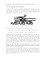
Agree on a reference time
Put all slave clock cards in the "standby" state
The site masters start polling the GPS cards
and wait for the reference time
When the time reaches 0.5 seconds before the reference
the masters send an "attention" pulse to all connected slaves
When the slaves receive the "attention" signal, they
wait for the next pulse on the PPS wire
When the PPS pulse arrives, it means the reference time
was reached and all slaves cards reset their counters
Figure 4.2: The steps involved in the synchronization procedure
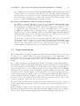
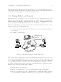
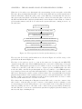
The steps involved in the synchronization are shown in Figure 4.2 and the setup on the
global scale is shown in Figure 4.3.
The slave clock cards are forced to count at the same rate by using the 10 MHz TTL
output from the GPS card. The 10 MHz signal is also connected to all the slave clock cards
inside a site. This signal is generated by an oscillator located on-board the GPS card. The
oscillator is controlled by the GPS receiver to output a precise 10 MHz signal. On other
words, the GPS controller keeps this signal as close as possible to a 10 MHz frequency.
A potential problem is the fact that this signal will be adjusted in different ways by each
GPS card. Among the possible reasons of such behavior are very small differences in the
physical characteristics of the crystals and the accuracy of the synchronization to the UTC.
Because of this, even after the initial reset all clocks are synchronized, we have to make
sure the synchronization is not lost after some time.
The solution involves using the 1 Hz pulse from the GPS card to reset the counters of the
slave cards to a known value at each occurrence of the signal. At the beginning of each
second (as triggered by the PPS pulse) we correct the values of the clock counters to known
values (by adding 40 * 106 to the value of the counter at the previous PPS). In this way,
the time difference between two synchronized systems is negligible (less then 500 ns) even
after several days of running freely.
CHAPTER 4. THE GPS-BASED CLOCK SYNCHRONIZATION SYSTEM
19
Local Site #1
Local Site #3
Internet
Local Site #2
Figure 4.3: Global synchronization over the Internet
4.3
Testing the method
The setup can be tested by telling all the cards in the system to save in the same time the
values of their clock counters. On a local site this is done using a wire from the master
clock card — when a pulse comes on this wire, the slaves save the time in a buffer memory.
The values in the buffers can be retrieved and compared afterwards. On a global scale the
saving of the counters is triggered by the PPS signal. Several tests were performed and we
concluded that the synchronization was functioning very well. For more information about
the tests see Appendix C on page 37.
Chapter 5
Traffic Generation
The network tester generates traffic according to a traffic description table that is loaded
into the network cards before a test is started. By network traffic we understand a stream
of packets. The way the packets are related inside the stream depends on the application,
but in general we can specify some statistical parameters that characterize the traffic.
Our traffic generator produces the packet stream according to a specified traffic pattern
description.
The traffic generator takes this description as an input and produces at the output a set
of packet descriptors. A packet descriptor is a group of some fields that characterize one
network packet. These fields can be: Source, Destination, Packet size, Inter packet time and
so on. These fields are all that we need to build a complete network packet. The additional
fields inside a packet (like checksum or length) are computed using this information.
5.1
Traffic profiles
Various types of traffic profiles (or traffic pattern descriptions) can be used. We can have
CBR traffic (Constant Bit Rate), bursts of packets, Poisson traffic, random, round robin or
any kind of combination of those. The user can create also his own custom traffic profiles.
The pattern description is specified by giving the statistical distribution for each of the
fields inside a packet descriptor (packet size, destination, inter packet time, etc). Then
the program generates random packets that have the required statistical characteristics. In
this way many kind of applications can be simulated and many types of traffic profiles are
possible. The distributions for different fields of the packet can be independent or correlated
such that some fields appear in pairs.
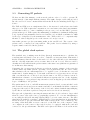
The output of the traffic generator is used to program the network cards to generate packets
according to the specifications. The Figure 5.1 shows a block diagram of the whole system.
At the end of the chain we have the post-processing software that will program the networking hardware to generate the traffic. Different post-processing software can produce
output for various types of hardware (network cards). Finally the network hardware is
programmed to generate the required traffic.
The fields inside a packet descriptor are shown in the following table:
20
CHAPTER 5. TRAFFIC GENERATION
<TrafficGeneratorConfiguration>
<FunctionDefinition name = "linear" parameters = "slope" >
slope * x
</FunctionDefinition>
<Pattern name = "sample1" number_of_descriptors = "4096" packet_type="1" >
<Source>
1:5, 10, 20:23
</Source>
<Destination>
round_robin(5, 10, 15 : 25)
</Destination>
<PacketSize>
RandomVar("gauss(x,900,10) + 2*gauss(x,1200,10)",800,1400)
</PacketSize>
<InterpacketTime>
rand_negexp(10)
</InterpacketTime>
</Pattern>
</TrafficGeneratorConfiguration>
Programmable Network Cards
Hardware
21
Traffic Generator
Software
91 1 8 5.000 0 23 1 10 82 308
98 1 23 5.000 0 1 2 5 45 100
101 1 0 5.000 0 3 3 10 32 106
116 1 9 5.000 0 22 1 10 8 294
94 1 3 5.000 0 5 2 1 57 285
101 1 3 5.000 0 1 3 10 83 286
115 1 26 5.000 0 25 1 1 13 317
88 1 4 5.000 0 20 2 5 46 295
86 1 2 5.000 0 23 3 10 85 305
Figure 5.1: Block diagram for the traffic generator
Field name
Source
Destination
Packet Size
Inter-packet Time
VLAN Id
VLAN Priority
IP ToS
Packet Type
Description
Specifies the source of the packets - an index in a table with real network addresses
(MAC or IP).
The index of the destination of the packet.
Can be a random variable with any distribution.
Size of the packet in bytes
The time between two consecutive packets. Usually it is a random variable with
a negative exponential distribution or a
”burst type” sequence.
The packets can belong to some Virtual
LANs. This field sets the distribution of
the IDs of those VLANs.
Sets the priority of the packet inside the
VLAN
Sets the IP Type of Service field.
The type of the packet: Ethernet or IP
The distributions that can be used for the fields are the following:
CHAPTER 5. TRAFFIC GENERATION
Distribution
rand normal( mean, stddev )
rand negexp( mean )
rand uniform( list )
round robin( list )
burst( burst length, inter
burst time, inter-packet time
within burst)
rand histogram( list of pairs:
value, probability)
RandomVar( ”expression depending on x”, min value,
max value)
22
Description
The Normal Gaussian distribution
with given mean and variance
Negative Exponential distribution –
usually used for inter-packet time
The values from the given list have
equal probability of appearance
The values from the list are chosen
one after the other
The values are from a burst-type
sequence. Used for inter packet
time to model packets that come in
bursts.
Each value has the given probability
of appearance
Generates a random number in the
interval [min value, max value] that
has the probability density given by
the expression from the first argument. The expression can be a function containing any built-in or userdefined function.
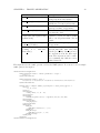
The input files for the traffic generator follow the XML syntax. You can see below a sample
traffic pattern description.
<TrafficGeneratorConfiguration>
<FunctionDefinition name = "linear" parameters = "slope" >
slope * x
</FunctionDefinition>
<FunctionDefinition name = "poly" >
26+(x/100-3)^5 -3*(x/100-3)^4 -11*(x/100-3)^3+27*(x/100-3)^2+10*(x/100-3)
</FunctionDefinition>
<Pattern name = "sample1" number_of_descriptors = "4096" packet_type="1" >
<Source>
1:5, 10, 20:23
</Source>
<Destination>
round_robin(5, 10, 15 : 25)
</Destination>
<PacketSize>
RandomVar("gauss(x,900,10) + 2*gauss(x,1200,10)",800,1400)
</PacketSize>
<InterpacketTime>
rand_negexp(10)
</InterpacketTime>
<VLAN_Data>
<VLAN_Id>
RandomVar("linear(3,x)", 0, 20)
</VLAN_Id>
<VLAN_Priority>
RandomVar("poly(x)", 0, 600)
</VLAN_Priority>
</VLAN_Data>
</Pattern>
</TrafficGeneratorConfiguration>
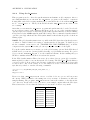
CHAPTER 5. TRAFFIC GENERATION
(a) Packet size
23
(b) VLAN Id
Figure 5.2: Sample histograms for the generated traffic
The histograms that result for two of the fields (packet size and the vlan id) are shown in
Figure 5.2
The traffic generator system can generate Ethernet frames when testing a Layer 2 environment (LAN) or streams of IP packets for the Internet. The following section presents some
results that were obtained with the network tester.
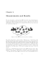
Chapter 6
Measurements and Results
The tester was put into operation in the CERN network and some measurements were
performed at the IP level ([7]). The system was composed of 2 PCs located in different
buildings inside CERN. We measured the average latency at different loads. For the clock
synchronization we used the GPS global clock system. The network topology between the
two ends is shown in Figure 6.1.
b513−bb10
Primergy
R
r513−gb8
GPS
1Gbps
R
1Gbps
1Gbps
Primergy
R
r513−an6
Primergy
R
R
b513−bb1
b513−gb8
1Gbps
100Mbps
100Mbps
b40−gb35
Primergy
r40−gb35
Primergy
R
1Gbps
R
Primergy
100Mbps
100Mbps
SWITCH
Primergy
100Mbps
PCATB56
GPS
r40−an4
1Gbps
Primergy
SWITCH
1Gbps
R
1Gbps
100Mbps
PCATBGPS01
Primergy
R
b40−bb10
Primergy
R
CERN
Network
b513−bb1
R = Router
Figure 6.1: The CERN network between the two buildings
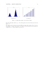
The packets pass through 5 routers and take a different route on each direction. The
packet size was 1518 bytes and the load was set to 20%. The Type of Service field in the
IP packets was also changed but no significant variations were observed. In Figure 6.2 we
show a latency histogram for the traffic between the two buildings. The sharp peak on the
left side in the distribution indicates that the load between the two building was rather
low, and packets were traversing the route without waiting in the queues in various routers
and switches. Knowing the exact configuration of the route we were able to calculate, that
the packets were spending 500 µs on wires and the remaining 540 µs inside routers and
switches.
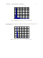
Another set of measurements was performed between CERN and Cracow ([8]). These
measurements are part of a feasibility study for moving part of the Atlas event processing
machines to off-site institutes. The first tests are using the existing network infra-structure
— the traffic passes through the CERN local network to Cracow via the GEANT backbone
24
CHAPTER 6. MEASUREMENTS AND RESULTS
25
Latency histogram
−3
x 10
18
16
14
12
10
8
6
4
2
0
1085
1090
1095
1100
1105
Latency [us]
Figure 6.2: Histogram of latencies for the test inside CERN
and national and regional networks. A histogram of latencies obtained during this test is
shown in Figure 6.3.
NORMALIZED LATENCY HISTOGRAM
0.18
0.16
0.14
0.12
0.1
0.08
0.06
0.04
0.02
0
20
30
40
50
LATENCY [ms]
60
70
80
Figure 6.3: Histogram of latencies between CERN and Cracow
Chapter 7
Conclusions and Future Work
The network tester was extended to an Internet environment. This implies IP traffic generation and global clock synchronization. The system can measure one-way latency, packet
loss, can build histograms. It can generate traffic according to the statistical distributions
of the fields of the packets and it can reach the Gigabit Ethernet line speed for all packet
sizes. The clock synchronization for one-way latency computation is achieved using the
GPS and CERN-designed clock cards.
The system will be used to evaluate the performance of long haul networks as part of a
feasibility study of locating the ATLAS third level trigger, the Event Filter, in remote
locations. Several tests were already done with the Institute of Nuclear Physics in Cracow
and others are about to follow.
26
Bibliography
[1] Testing and Modeling Ethernet Switches and Networks for use in ATLAS High-Level
Triggers
Dobinson, R W; Haas, S; Korcyl K; Le Vine, M J; Lokier, J; Martin, B; Meirosu, C;
Saka, F; Vella, K;
in: IEEE Trans Nucl Sci.: 48 (2001) no. 3 pt. 1 pp.607-12
[2] Testing Ethernet networks for the ATLAS data collection system
Barnes, F R M; Beuran, R; Dobinson, R W; Le Vine, M J; Martin, B; Lokier, J;
Meirosu, C
in: IEEE Trans Nucl. Sci.: 49 (2002) no. 1 pp.516-20
[3] Advanced Network Tester User’s Guide v2.0 4.04.2002
Catalin Meirosu
[4] GPS Synchronization Status Report
Miron Brezuleanu, Matei Ciobotaru, Catalin Meirosu; 28 May 2002
[5] GPS Sync - notes and documentation
Miron Brezuleanu, December 2001; available in the distribution directory
[6] GPS167PCI GPS Clock User’s manual
Meinberg Funkuhren
[7] Layer 3 measurements through the CERN network
Mihai Ivanovici, Marcia Maia, Catalin Meirosu
[8] Network performance measurements for massive data transfers between CERN/Geneva
and Cyfronet/Cracow
Krzysztof Korcyl, Grzegorz Sladowski, Razvan Beuran, Robert W. Dobinson, Mihai
Ivanovici, Marcia Losada Maia and Catalin Meirosu
[9] Low-cost Precise QoS Measurement Tool
Sven Ubik, Vladimir Smotlacha, Sampo Saaristo, Juha Laine;
Tampere University of Technology, Finland
[10] GPS Time Synchronization System for K2K
H. G. Berns, R. J. Wilkes – Department of Physics, University of Washington;
http://www.phys.washington.edu/∼berns/RT99/
[11] IXIA IxCore Data-sheet
http://www.ixiacom.com/pdfs/DS-IxCore.pdf
27
Appendix A
Installation
The installation consists in placing the GPS and clock boards in the computers, connecting
the cables and the GPS antenna and installing the required software.
A.1
Technical requirements
The following hardware resources are used:
• One GPS card per master computer per site
• GPS Antenna and cable
• Clock card in each computer in the system
• Cables and T connectors to interconnect the clock cards
The following software is needed for the system so perform properly:
• Linux operating system - kernel version 2.4.6 or greater
• Meinberg GPS drivers - MBG Tools for Linux 0.2.3beta
• Clock card kernel module - HSLCLOCK version adapted to work with the GPS
• TCP/IP network connection and xinetd server
A.2
Hardware
The GPS system works only if the antenna is properly mounted - it should be placed in a
location from which as much sky as possible can be seen - preferably on the roof of some
building. Check the output of the mbgstatus program to see if the antenna is properly
mounted. The GPS should see more than 7 satellites.
For the system to work properly, the switches on the GPS cards should have the following
configuration:
28
APPENDIX A. INSTALLATION
29
• switch 10 - ON (10MHz clock on pin 4)
• switch 4 - ON (1Hz pulse on pin 8)
• all other - OFF
Also some clock cards have to be installed into the computers. In the computer with the
GPS card you have to put a master clock card and in the others - slave clock cards (in fact
you can put master cards in all computers). The GPS is working fine if the green LED
is ON (on the connector of the board). You can also see if the GPS is working using an
oscilloscope. You should be able to see the 10MHz and the 1Hz signals.
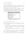
NOTE: The signals are available only after the GPS has synchronized with the satellites
- mbgstatus should show something like in Figure A.1.
A.3
Cable connections
If a local group consists of only one computer then the cable connections are the following:
GPS serial port – pin 4 (10MHz -clock)
→ input #1 on the clock board
GPS serial port – pin 8 (1Hz PPS)
→ input #3 on the clock board
output #2 (fire out) on the master clock board
→ input #4 on the same board (fire in)
If the local group contains one or more slave clock boards:
GPS serial port - pin 4 (10MHz clock)
using T connectors - at input #1
→ should be distributed to all clock cards
GPS serial port - pin 8 (1Hz PPS) → should be distributed to all clock cards using
T connectors - at input #3
output #2 (fire out) on the master clock board
→ should be distributed to
all clock cards using T connectors - at input #4 (fire in). From the last clock card in
the chain it should return to the master clock cards also at input #4.
NOTE: Be careful about connecting the slaves & master clock cards! The inputs of the
master should be the last to be connected, as the masters has the terminators. So even if
”fire out” has to be plugged back in the master’s ”fire in”, it should be first teed through
everybody else’s ”fire in” and be plainly connected to the master ”fire in” to get the input
in the master and to get a terminator. More information about this: the logbooks and
Brian himself.
A.4
Software
The software is made up of 2 kernel modules and some driver programs that control the
synchronization procedures.
APPENDIX A. INSTALLATION
A.4.1
30
The GPS card driver
The GPS kernel module is provided by Meinberg – we are using MBGtools for Linux
v0.2.3beta. On the local master computers you need to install the GPS kernel module –
mbgclock.o . The solution was tested with Linux kernels 2.4.4 and 2.4.6. It seems that
the Meinberg kernel module does not work on Linux 2.4.2.
The module has to be compiled first for the local kernel version. You have to go into the
directory mbgtools-lx-0.2.3- beta and type make . After this you can install the
module using insmod mbgtools-lx-0.2.3-beta/mbgclock/mbgclock.o .
Check the file /var/log/messages to see if the module loaded successfully. The device
associated with the GPS card is /dev/mbclk . To check that the GPS is working - run the
script gps status.sh . You should see something like in the Figure A.1:
Figure A.1: The GPS status window
A.4.2
The clock card kernel module
The module for the clock card has to be also compiled and installed. You have to go to the
directory hslclock module and type compile.sh . The compilation of the clock module
consists of two phases:
• The compilation of the firmware (in Handel-C) that produces the file hslclock module/hslclock.ttf . This compilation uses Razvan Beuran’s computer and should
be done only once on any machine because it does not use any kernel information.
See [4] for more information.
• The actual compilation of the kernel module – it produces the file hslclock module/hslclock.o This file depends on the current kernel.
After the compilation ends, you load the module using insmod hslclock module/
hslclock.o . Check also /var/log/messages for any errors. The devices associated
to the clock cards are /dev/hslclock0, /dev/hslclock1, ...
After the modules are loaded you should check that the clock is counting. The initial state
of the board does not allow time readings. To enable this you have to run the command
APPENDIX A. INSTALLATION
31
clock test/clock test 1 3 which sends the command ”3” (READ TIME) to board
number 1 (the first board /dev/hslclock0 ). Then you can run dump hslclock.sh 1 to
see if the clock is counting.
NOTE: In order for the clock card to work, it has to be connected to the 10MHz signal
from the GPS card – otherwise the counter does not change.
A.4.3
The manager program – HS MASTER
If the GPS and the clock are working fine then you can configure the hs master program
from the directory hsmaster . First you have to install hs daemon on each computer
involved in the synchronization process. For this you have to configure the (x)inetd
server to load hs daemon when a request at some port is made.
A simple way to configure xinetd is to copy the files from directory hsmaster/xinetd config to the directory /etc/xinetd.d . You may need to modify those files ( hs daemon
and hs daemon1 ) to specify the correct path to the hs daemon executable (on the line
”server = ....”). This path should be readable by all users. If you have problems please
refer to [4] for more details about this configuration.
NOTE: A hs daemon program should be installed on all the nodes that require synchronization and have a clock card inside, INCLUDING the ”master” node. The program
creates also some log files in the /tmp directory on the local machines ( hsdaemon log*.txt and hsdaemon results*.txt )
The master node is the node that hosts the GPS card. On this computer you will run the
hs master program. While hs daemon is an executable that can be placed in /usr/bin
on all the computers, hs master requires the presence of the program hs client in the
same directory as itself. It also requires the presence in the same directory of a configuration
file called hs nodes.conf . This file has lines of the form hostname:port listing all the
hostname : port combinations that correspond to local clock cards. DON’T FORGET to
list here the clock card in the master itself or it will be left out in all the operations!
An example of the contents of the hs nodes.conf could be:
pcstuff01.cern.ch:40000
pcstuff01.cern.ch:40001
pcstuff02.cern.ch:40000
Note that pcstuff01.cern.ch has two clock boards inside and it uses different ports for each
card. pcstuff02.cern.ch has a single card and uses port 40000.
NOTE: Important: You have to create a different hs nodes.conf file for each local
group of computers (site) that depends on a GPS card. Don’t list in this file machines from
other groups. On each master of each group you should run an instance of the hs master
program with a different configuration file.
To check that the system is working you can open a terminal window with dump hslclock.sh and use the Simple Synchronize option in hs master to see if the clock is
reset at some point (do not use the PPS Sync Thread option for this). Then you can use
the global synchronization tests to verify the whole system.
APPENDIX A. INSTALLATION
A.4.4
32
Using the hs master
This program is used to drive the synchronization mechanism on all computers. After a
successful installation you can start the hs master program on all ”master” computers
hosting GPS cards. Before trying anything else you should set the clock cards in READ TIME
mode: clock test 1 3 . Then you should check with dump hslclock.sh if the clocks
are counting.
After this you can start the hs master program and synchronize the boards. You decide
upon a reference time for all computers and then you choose one of the 2 synchronization
options. Option 1 resets the clocks at the specified time and after this the clocks are running
freely (driven by the 10MHz signal from the GPS cards). The recommended synchronization
option is option (6) which uses the PPS synchronization thread that keeps the clocks from
drifting apart.
NOTE: The global synchronization is not possible if the PPS Sync thread is already active
- you have to disable it first before trying to synchronize the clocks again. To disable it you
use the command clock test 1 14 [ DISABLE PPS SYNC THREAD (14) ] on all the
computers in the system. After this you can try to synchronize the clocks again.
To test the synchronization you can use one of the global testing options. If the PPS thread
is NOT active you can use options (3)-Global testing or (5)-Continuous testing. For option
(5) you can use hsdaemon log.sh to see the results in real-time. In the resulting files you
should see similar values from all clock cards in the system.
If the PPS Synchronization Thread is active (if you have chosen option (6) for synchronization) then you have to use another method for testing. The PPS Sync Thread makes a
correction of the clock at each second. Because of this if we read directly the clock at each
second we’ll see only ”ideal” values. To see the values before the correction from the PPS
sync thread you have to run the following commands:
clock_test 1 16 [ SET_READMODE_LAST_BAD_CLOCK_VALUE (16) ]
and then
dump_hslclock.sh 1
Please note that dump hslclock.sh tries to read the clock once per second but it uses
the sleep UNIX command so the timing is not very accurate. Sometimes you will some
samples missing. The program dump hslclock.sh writes the results to some files in the
”res” directory. In the table below you can see some sample outputs when the PPS Sync
Thread was active. Notice that the differences between the clocks are very small.
Clock 1
3843919866
3883919867
3923919867
3963919867
4003919867
4043919867
4083919867
4123919867
4163919868
Clock 2
3843919863
3883919867
3923919868
3963919868
4003919867
4043919867
4083919867
4123919868
4163919867
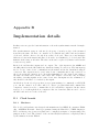
Appendix B
Implementation details
In this section we give the basic information on how the synchronization method is implemented.
The synchronization setup at each site (local group of nearby nodes) of the measured
network is the same. We have one ”master” node which hosts a GPS card and a master
clock card. All the other nodes only host a slave clock card. There are some hardware
differences between the master and slave clock cards - see Catalin’s log book for detail. The
firmware is the same on all cards. The slave cards can be replaced by master cards but the
reverse is not possible.
Each clock card has three inputs and one output. Two of the inputs are the 10MHz and
the 1Hz pulses from the GPS which are distributed using T connectors. The last input is
used to receive ”write down” commands from the master and is also distributed using T
connectors. The output is used to send ”write down” commands and is only connected on
the clock card in the ”master” node. It is then transmitted to the ”write down” input of
the same card then sent to all the other cards. The ”master” card is the only one having
the ability of sending signals on the ”write down” wire. Its inputs are also terminated, so
they should be the last to be reached by the signal.
On all the nodes in a local group there is a program waiting for commands on a TCP/IP
port. On the ”master” node there will be a ”driver” program which will command the
computers – in fact we need to command the clock boards in the computers, but the easiest
way is to do so is through the host computers. Also two kernel modules are used - one for
the GPS card and one for the clock card.
B.1
B.1.1
Clock boards
Hardware
The clock board hardware was designed and manufactured at CERN. It contains a FPGA
chip - ALTERA Flex 10k - that is programmed using the Handel-C / VHDL languages.
The board has 4 ports (connectors) that can be configured as inputs or outputs using some
jumpers on the board. The behavior of the card and its I/O features are completely defined
by the firmware from the FPGA.
33
APPENDIX B. IMPLEMENTATION DETAILS
34
For this project we use to types of clock cards: master cards and slave cards. The only
difference between them is that the master cards have the Write Down Output enabled.
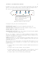
The connectors of the clock cards are shown in the figure Figure B.1.
24
Port #1
Port #2
Port #3
Port #4
Port #1 − 10 MHz clock from GPS (input)
Port #2 − Write down (OUTPUT) − only for master card
Port #3 − 1 Hz PPS signal from GPS (input)
Port #4 − Write down (input)
Figure B.1: Connectors on the clock board
A description of the ports of the clock cards is given below.
WRITE DOWN (input) For the special commands from the master card
GPS PPS (input) The 1Hz signal from the GPS card (PPS = Pulse Per Second)
CLOCK (input) The 10MHz clock from the GPS
WRITE DOWN (OUTPUT) Active only for master clock cards. It sends commands
to slaves and is connected to all the boards.
The type of a port (input or output) can be modified by making some hardware modifications on the board. There are a lot of clock boards available, but most of them are not yet
modified to work with the new configuration.
NOTE: Brian Martin’s logbook shows information about the jumper settings on the clock
cards. There is also some concise info on the I/O configuration of the board connectors in
Catalin Meirosu’s logbook.
There are already 4 clock cards modified for use with the GPS. Their numbers are noted
in Catalin’s logbook. More cards will need to be modified to test a complete setup. The
modified boards are:
• board #37 - master clock card, works fine - was used for initial tests (it was also used
by Miron).
• board #33 - slave clock card, works fine - also used by Miron
• board #24 - master clock card - recently modified - some problems were observed
with the continuous GPS testing (strange numbers appear from time to time).
• board #31 - master clock card - has the same problems as #24
APPENDIX B. IMPLEMENTATION DETAILS
B.1.2
35
Software and Firmware
The firmware is the program that is implemented by the FPGA and that controls all
the activity of the clock board. The firmware is written in Handel-C/VHDL. After the
compilation of the sources of the firmware one gets a hardware description/implementation.
This description is fitted for the FPGA using a software package called Altera MAX PLUS
II software.
The computer hosting the clock board controls it via a Linux kernel module. This module,
when it is loaded, writes the firmware into the FPGA. So if we need a new behavior for the
clock board, we have to compile a new firmware and then reload the kernel module.
B.2
GPS cards
Currently there are 2 identical GPS cards produced by a German company called Meinberg
- the model is GPS167PCI. The GPS card fits into a PCI slot of the computer. There
are some switches on the card that can enable or disable certain outputs – their state for
normal functioning will be given later. The card has a 9-pin serial port that provides on
some of its pins the 10MHz and the 1Hz PPS signals. These signals are distributed to all
clock cards in a local site using wires and T connectors.
For easier identification, the cards are marked with some numbers (on the white label from
the card). The card #1 was used for the initial test with only one computer. The firmware
from this card was upgraded from version 4.16 to version 4.18.
The card #2 had some problems at the beginning - the 10MHz clock was not available at
the output pin (pin number 4 on the serial connector), so we had to get this signal directly
from the 5pin jumper block located near the board bus connector.
NOTE: There is a mistake in the manual - the pin number 1 is located near the bus
connector, not pin number 5.
For the system to work properly, the switches on the cards must have the following configuration:
• switch 10 - ON (10MHz clock on pin 4)
• switch 4 - ON (1Hz pulse on pin 8)
• all other - OFF
You can also enable the time capture inputs of the GPS boards (switches 2 and 3 - ON).
After this, a falling TTL slope at one of the inputs (pins 6 or 7) lets the microprocessor
save the current real time in its capture buffer. You can use the program mbgtools-lx0.2.3-beta/mbggpscap/mbggpscap to see the data from this buffer.
The firmware on the GPS card can be upgraded when new version are provided by the
manufacturer.
APPENDIX B. IMPLEMENTATION DETAILS
B.3
36
Manager software
The driver software consists of 3 small programs that work together:
hs master This is the manager program on a site. At each site there is only one instance
of hs master that runs on the master computer. This program uses the services of
the GPS card and sends commands to the other computers.
hs daemon It is the program that listens to commands from the hs master and talks
directly to the clock cards. It runs on each computer from the system. It is supposed
to be registered by the inetd server.
hs client Is a helper program for hs master used to facilitate the communication
via a TCP/IP network.
The source files can be found in the hsmaster directory. hs client and hs daemon
aren’t called directly by the user, only hs master is. hs daemon is supposed to be registered with inetd or xinetd to run as a daemon. It only knows to receive a request/command
on stdin and to output a reply on stdout. All the commands that it receives are executed on
the local clock card. The socket listening is done by (x)inetd. See the installation section
for more details about this.
The hs master program checks if the clock card and GPS card kernel modules are loaded.
If they aren’t the program fails with a message telling why. Most errors encountered by
hs master are considered fatal, as they prevent the synchronization process from working.
The options available in the hs master menu correspond to the main procedures for the
synchronization and testing of the setup. The most important option is the one called
”Sync with PPS thread”. This is the most accurate option for synchronization because it
updates the clocks at each second to keep them from drifting apart.
Appendix C
Results obtained during
development
A lot of testing was performed to verify the method (see [4]). The first tests were intended to
check the GPS cards and to see how well they behave. Then some tests and measurements
were done to see if the synchronization method is working.
C.1
Testing the GPS card
The GPS card can provide position and timing information to the host computer. Using
a small utility program ( mbgstatus ) that comes from the manufacturer (Meinberg) we
gathered all positional parameters delivered by the GPS. The test was done using a GPS
card that had the antenna on the roof of a building and the card reported full strength
satellite signal and 9 satellites in view.
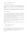
The values were written to some files and analyzed and plotted using Matlab. We recorded
the altitude, latitude, longitude and x, y, z coordinates. A full set was parameters was read
from the GPS every 5 seconds for several days. The Figure C.1 shows the graphs of these
parameters as they vary in time. There are large variations (especially for the altitude
which varies with 100 meters) but the manufacturer says that this is normal and it does
not affect the timing accuracy.
C.2
Local synchronization test
This test was done on a computer with 2 clock cards (master and slave) that were driven
by the same GPS card (hosted by the same computer). We synchronized the clocks and
then we took sample values of the clock counter at each pulse on the 1Hz PPS wire from
the GPS. The samples did not differ by more than one clock tick (because of the phase shift
between the 10MHz and the 1Hz signals) so the results were satisfactory.
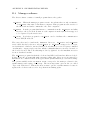
Another measurement was done to see the duration of one second in clock ticks. As we
said before, the GPS provides a 10MHz signal and the clock boards derive from it a 40MHz
signal, so the duration of one second should by always 40000000 clock ticks. We measured
37
APPENDIX C. RESULTS OBTAINED DURING DEVELOPMENT
38
Figure C.1: GPS Positional parameters for a period of 5 days
the difference between the values samples at two consecutive 1Hz PPS pulses and we saw
that the values varied between 39999995 and 40000005. These was explained by the fact
that the GPS adjusts its output signals to match the satellites.
Figure C.2: Ticks per second
C.3
Global synchronization test
For this test we installed 2 GPS cards in two computers located in different buildings.
The distance between the buildings was of several hundred meters and the antennas were
mounted on the roofs of the buildings.
There are two different methods for global synchronization - one that uses a periodic update/correction of the clocks and one that does not. Both methods use the same procedure
for the initial reset.
The method without the periodic update is not accurate enough for our purposes (the
APPENDIX C. RESULTS OBTAINED DURING DEVELOPMENT
39
clocks lose their synchronization [4]) so the preferred method is the one that corrects the
clocks at each second.
The test involves recording the values of all counters in the system at each second, as
triggered by the 1Hz PPS signal from the GPS. The table found in Appendix A.4.4 on page
32 shows some of these values.
A second test was to run ping type program (echo – reply) that measures the one-way
delay and the round trip time between the 2 sites. Some results are given below and can
be observed that the one-way delay is half of the round trip time.
64 bytes from pcatbgps01.cern.ch
icmp_seq=7 ttl=250 time=758 usec
64 bytes from pcatbgps01.cern.ch
icmp_seq=8 ttl=250 time=756 usec
64 bytes from pcatbgps01.cern.ch
icmp_seq=9 ttl=250 time=761 usec
(137.138.203.40):
oneway delay: 360.448000 usec
(137.138.203.40):
oneway delay: 368.640000 usec
(137.138.203.40):
oneway delay: 376.832000 usec
Appendix D
GPS Synchronization HOW-TO
1. Install the cards and connect the cables
2. Load the kernel modules: for GPS mbgclock.o and clock card hslclock.o
3. Make sure that the modules for the GPS and the clock card are loaded and fully
functional:
• Check the file /var/log/messages to see if the modules are loaded properly
• For the clock card: use the script dump hslclock.sh to see if the clock is
counting
• For the GPS card: use the program mbgstatus to see if the antenna is properly
connected and if the card is synchronized
4. Verify that the xinetd server is properly installed and put the configuration for
hs daemon into /etc/xinetd.d/hs daemon Make sure you set the correct path to
the program hs daemon . This must be done on ALL computers in the system. You
might need root privileges to do this.
5. Make sure the clock is in the ”Read time” mode. Run the command:
clock_test 1 3
6. Make sure that the PPS thread is disabled. Run the command:
clock_test 1 14
7. Try to reset the clock manually:
• Open a window with dump hslclock
• In another window run these 2 commands, one after the other:
clock_test 1 1
clock_test 1 2
• See if the clock resets after these 2 commands
This test has to be made at all sites that need to be synchronized.
8. Open a terminal window for each of the computers in the system and a terminal
window for each of the master computers in the system.
40
APPENDIX D. GPS SYNCHRONIZATION HOW-TO
41
9. Configure the file hs nodes.conf at each of the sites. In this file you list ONLY the
computers from that site - do not list computers from other sites. For example:
pcatb56.cern.ch:40000
10. Start the hs master program on the master computer at each of the sites.
11. Choose the option ”Synchronize with PPS thread”
12. Enter the same time on all the master computers, but take into account the local
time. The program will report the time from the local GPS - you have to give the
reference time with respect to that time.
13. After this the master computers will wait for the reference time and when it comes,
they will reset the local clock cards. See the windows with the clock dumps to check
if they reset. Now the cards should be globally synchronized.
14. To check the synchronization:
• Put the clock cards in mode 16 (read last bad clock value):
clock_test 1 16
This command tells the clock card to output not the value of the counter, but
the value of the counter before the PPS correction is made.
• Check the numbers that appear in the clock dumps – they should be similar.
• Put the clock cards back into the normal mode (read time):
clock_test 1 3
Appendix E
Troubleshooting synchronization
problems
Problems with the cables
• If the clock is not counting - probably the 10MHz signal from the GPS is not
plugged into the clock card.
• If the GPS does not synchronize, check the antenna connection and that the
antenna sees enough open sky (NOTE: in this case the clock card will not count
because the 10MHz signal will not be available).
• If the clock is counting, the GPS is ok and the clock card does not reset on
request - there might by a problem with 1 Hz PPS signal from the GPS or with
the Write Down signal from the master clock card.
The hs master program
• If the hs master can’t communicate with the slaves – check the xinetd configuration and the hs nodes.conf . Make sure only valid local site nodes
are listed there and also that the local master is in that file. Check the file
/etc/xinetd.d/hs daemon and make sure you have the correct path to the
hs daemon executable.
• The synchronization is not done – check the cables, try to manually reset the
clock cards, check if the GPS card is synchronized.
The clock cards
• The clock cards do not reset – make sure the PPS sync thread is not active (
clock test 1 14 ) and that the card is in the read time mode ( clock test
1 3 ). Also make sure that the master clock card is really a master card (you
can try to see the signals with an oscilloscope).
• The clock counter is 0 – send the read time command to the card: clock test
1 3
• The clock counter has a constant value different from zero – this looks like the
10MHz signal is no longer available – check the cables and the GPS.
42
APPENDIX E. TROUBLESHOOTING SYNCHRONIZATION PROBLEMS
43
The GPS cards
• Time is not synchronized – check the antenna and the cable. The card should
see more than 3 satellites. Please note that when moved to a new location, the
card needs around 15 minutes to synchronize.
• The 10MHz and PPS signals are not available – check the jumpers on the card
to activate these outputs.
Other problems
• If the kernel modules can’t be loaded – probably they need to be recompiled for
the current linux kernel version.