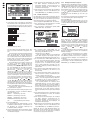
1
DIGITALER MULTIPLEXREKORDER DIGITAL MULTIPLEX RECORDER DMR -180 SET Best.-Nr. 18.2380 DMR -184 DMR -188 Best.-Nr. 18.2620 Best.-Nr. 18.2610 BEDIENUNGSANLEITUNG INSTRUCTION MANUAL MODE D’EMPLOI ISTRUZIONI PER L’USO MANUAL DE INSTRUCCIONES VEILIGHEIDSVOORSCHRIFTEN ŚRODKI BEZPIECZEŃSTWA SIKKERHEDSOPLYSNINGER SÄKERHETSFÖRESKRIFTER TURVALLISUUDESTA D Bevor Sie einschalten … A Wir wünschen Ihnen viel Spaß mit Ihrem neuen Gerät von MONACOR. Bitte lesen Sie diese Bedienungsanleitung vor dem Betrieb gründlich durch. Nur so lernen Sie alle Funktionsmöglichkeiten kennen, vermeiden Fehlbedienungen und schützen sich und Ihr Gerät vor eventuellen Schäden durch unsachgemäßen Gebrauch. Heben Sie die Anleitung für ein späteres Nachlesen auf. We wish you much pleasure with your new MONACOR unit. Please read these operating instructions carefully prior to operating the unit. Thus, you will get to know all functions of the unit, operating errors will be prevented, and yourself and the unit will be protected against any damage caused by improper use. Please keep the operating instructions for later use. Der deutsche Text beginnt auf der Seite 4. The English text starts on page 22. CH GB Before switching on … F Avant toute installation … B Nous vous souhaitons beaucoup de plaisir à utiliser cet appareil MONACOR. Lisez ce mode dʼemploi entièrement avant toute utilisation. Uniquement ainsi, vous pourrez apprendre lʼensemble des possibilités de fonctionnement de lʼappareil, éviter toute manipulation erronée et vous protéger, ainsi que lʼappareil, de dommages éventuels engendrés par une utilisation inadaptée. Conservez la notice pour pouvoir vous y reporter ultérieurement. Vi auguriamo buon divertimento con il vostro nuovo apparecchio di MONACOR. Leggete attentamente le istruzioni prima di mettere in funzione lʼapparecchio. Solo così potete conoscere tutte le funzionalità, evitare comandi sbagliati e proteggere voi stessi e lʼapparecchio da eventuali danni in seguito ad un uso improprio. Conservate le istruzioni per poterle consultare anche in futuro. La version française se trouve page 34. Il testo italiano inizia a pagina 52. CH E Antes de la utilización … Le deseamos una buena utilización para su nuevo aparato MONACOR. Por favor, lea estas instrucciones de uso atentamente antes de hacer funcionar el aparato. De esta manera conocerá todas las funciones de la unidad, se prevendrán errores de operación, usted y el aparato estarán protegidos en contra de todo daño causado por un uso inadecuado. Por favor, guarde las instrucciones para una futura utilización. I NL B Prima di accendere … Voor u inschakelt … Wij wensen u veel plezier met uw nieuwe apparaat van MONACOR. Lees de veiligheidsvoorschriften grondig door, alvorens het apparaat in gebruik te nemen. Zo behoedt u zichzelf en het apparaat voor eventuele schade door ondeskundig gebruik. Bewaar de handleiding voor latere raadpleging. De veiligheidsvoorschriften vindt u op pagina 94. El texto en español empieza en la página 76. PL Przed uruchomieniem … DK Życzymy zadowolenia z nowego produktu MONACOR. Prosimy zapoznać się z informacjami dotyczącymi bezpieczeństwa przed użytkowaniem urządzenia, w ten sposób zdrowie użytkownika nie będzie zagrożone, a urządzenie nie ulegnie uszkodzeniu. Instrukcję należy zachować do wglądu. Før du tænder … Vi håber, du bliver glad for dit nye MONACOR produkt. Læs sikkerhedsanvisningerne nøje før ibrugtagning, for at beskytte Dem og enheden mod skader, der skyldes forkert brug. Gem manualen til senere brug. Sikkerhedsanvisningerne findes på side 94. Informacje dotyczące bezpieczeństwa znajdują się na stronie 94. S Innan du slår på enheten … Vi önskar dig mycket glädje med din nya MONACOR produkt. Läs igenom säkerhetsföreskrifterna innan enheten tas i bruk för att undvika skador till följd av felaktig hantering. Behåll instruktionerna för framtida bruk. Säkerhetsföreskrifterna återfinns på sidan 95. FIN Ennen kytkemistä … Toivomme Sinulle paljon miellyttäviä hetkiä uuden MONACOR laitteen kanssa. Ennen laitteen käyttöä pyydämme Sinua huolellisesti tutustumaan turvallisuusohjeisiin. Näin vältyt vahingoilta, joita virheellinen laitteen käyttö saattaa aiheuttaa. Ole hyvä ja säilytä käyttöohjeet myöhempää tarvetta varten. Turvallisuusohjeet löytyvät sivulta 95. 2 DMR-180/-184 1 2 3 10 17 DMR-188 1 2 4 11 5 12 18 3 10 17 13 14 19 13 14 24 6 18 19 20 21 22 23 24 29 35 31 36 a b 3 26 9 16 32 34 8 15 33 30 9 25 7 27 28 8 16 5 12 7 15 20 21 22 23 4 11 6 25 26 D Inhalt A 1 CH Übersicht der Bedienelemente und Anschlüsse . . . . . . . . . . . . . . . . . . . . . . . . . 4 10 Alarmfunktionen . . . . . . . . . . . . . . . . . . . . 14 Auf der ausklappbaren Seite 3 finden Sie alle beschriebenen Bedienelemente und Anschlüsse. 10.1 Alarmkonfiguration . . . . . . . . . . . . . . . . . . . 14 1.1 Vorderseite des Rekorders . . . . . . . . . . . . . . 4 10.2 Benachrichtigung per E-Mail . . . . . . . . . . . 14 1.2 Rückseite des Rekorders . . . . . . . . . . . . . . . 4 10.3 Bewegungserkennung . . . . . . . . . . . . . . . . 15 1.3 Infrarot-Fernbedienung . . . . . . . . . . . . . . . . . 5 11 2 Hinweise für den sicheren Gebrauch . . . . 5 11.1 Einrichten der Steuerparameter . . . . . . . . . 15 3 Einsatzmöglichkeiten . . . . . . . . . . . . . . . . . 5 11.2 Steuerung einer Kamera . . . . . . . . . . . . . . 15 4 Festplatte einbauen . . . . . . . . . . . . . . . . . . 5 1 Ein-/Ausschalter 11.3 CRUISE-Funktion einrichten . . . . . . . . . . . 15 5 Geräte anschließen . . . . . . . . . . . . . . . . . . 5 2 Betriebsanzeige PWR 11.4 CRUISE-Funktion aktivieren / deaktivieren . 16 3 Infrarotempfänger für die Fernbedienung; Fernbedienung auf diesen Sensor richten 12 5.2 Audioanschlüsse . . . . . . . . . . . . . . . . . . . . . 5 12.1 Passwortschutz einrichten . . . . . . . . . . . . . 16 5.3 Alarm- und Steueranschlüsse . . . . . . . . . . . 6 12.2 Passwortschutz aktivieren . . . . . . . . . . . . . 16 5.3.1 Alarmeingänge . . . . . . . . . . . . . . . . . . . . . 6 13 5.3.2 Alarmausgang . . . . . . . . . . . . . . . . . . . . . . 6 13.1 Systeminformationen anzeigen . . . . . . . . . 17 Passwortschutz . . . . . . . . . . . . . . . . . . . . 16 Systemwartung . . . . . . . . . . . . . . . . . . . . . 17 5.3.3 Kamerafernsteuerung (PTZ) . . . . . . . . . . . 6 14 5.4 Maus . . . . . . . . . . . . . . . . . . . . . . . . . . . . . . . 6 14.1 Einrichten einer Netzwerkverbindung . . . . . 17 5.5 USB-Speichermedium . . . . . . . . . . . . . . . . . 6 5.7 Netzanschluss . . . . . . . . . . . . . . . . . . . . . . . 6 14.2 Fernbedienung über die Programme Windows Internet Explorer oder 9D-VIEWER . . . . . . . . . . . . . . . . . . . . 18 5.8 Batterien in die Fernbedienung einsetzen . . 6 14.2.1 Ansicht „LIVE“ . . . . . . . . . . . . . . . . . . . . . 18 6 Inbetriebnahme . . . . . . . . . . . . . . . . . . . . . . 6 14.2.1.1 Momentaufnahmen speichern . . . . . . . 18 6.1 Aufruf des Bildschirmmenüs . . . . . . . . . . . . . 6 14.2.1.2 Videosequenzen aufzeichnen . . . . . . . 18 6.2 Grundeinstellungen . . . . . . . . . . . . . . . . . . . 7 14.2.1.3 Kamerasteuerung (PTZ CONTROL) . . 18 6.2.1 Menüsprache ändern . . . . . . . . . . . . . . . . 7 14.2.2 Ansicht „REPLAY“ . . . . . . . . . . . . . . . . . . 19 6.2.2 Videoeinstellungen . . . . . . . . . . . . . . . . . . 7 14.2.2.1 Wiedergabesteuerung . . . . . . . . . . . . . 19 6.2.3 Kameranamen . . . . . . . . . . . . . . . . . . . . . . 7 14.2.2.2 Videodateien konvertieren . . . . . . . . . . 19 6.2.4 Datum und Uhrzeit . . . . . . . . . . . . . . . . . . 8 14.2.3 Ansicht „SETUP“ . . . . . . . . . . . . . . . . . . . 19 6.2.5 Bildeigenschaften korrigieren . . . . . . . . . . 8 14.2.3.1 SETUP/ RECORD . . . . . . . . . . . . . . . . 19 7 Live-Überwachung . . . . . . . . . . . . . . . . . . . 9 14.2.3.2 SETUP/ALARM . . . . . . . . . . . . . . . . . . 20 7.1 Anzeigeoptionen . . . . . . . . . . . . . . . . . . . . . . 9 14.2.3.3 SETUP/ PTZ . . . . . . . . . . . . . . . . . . . . . 20 7.2 Sequenzfunktion einrichten . . . . . . . . . . . . . 9 14.2.3.4 SETUP/ NETWORK . . . . . . . . . . . . . . . 20 7.3 Sequenzfunktion aktivieren/ deaktivieren . . . 9 14.2.3.5 SETUP/ SETTING . . . . . . . . . . . . . . . . 20 8 Aufnahme . . . . . . . . . . . . . . . . . . . . . . . . . . 9 14.2.3.6 SETUP/ HOST INFO . . . . . . . . . . . . . . 21 8.1 Generelle Aufnahmeeinstellungen . . . . . . . . 9 14.2.4 Ansicht „LOGOUT“ . . . . . . . . . . . . . . . . . 21 8.1.1 Einrichten / Löschen der Festplatte . . . . . 10 14.3 Fernzugriff über ein Mobiltelefon . . . . . . . . 21 8.2 Aufnahmesteuerung . . . . . . . . . . . . . . . . . . 10 15 8.2.1 Ständige Aufnahme . . . . . . . . . . . . . . . . . 10 8.2.2 Manuell gestartete Aufnahme . . . . . . . . . 10 8.2.3 Zeitgesteuerte Aufnahme . . . . . . . . . . . . 10 8.2.4 Alarmgesteuerte Aufnahme . . . . . . . . . . 11 8.2.5 Einblendungen während der Aufnahme . 11 8.2.6 Speicherung nach Aufnahmetyp . . . . . . . 11 9 Wiedergabe . . . . . . . . . . . . . . . . . . . . . . . . 11 9.1 Export von Videodateien . . . . . . . . . . . . . . 12 9.1.1 Formatieren des USB-Speichermediums 12 9.2 Wiedergabe von Aufzeichnungen mit dem Programm PLAYBACK . . . . . . . . . . . . . . . . 12 9.2.1 Videodateien öffnen . . . . . . . . . . . . . . . . 12 9.2.1.1 Eine einzelne Videodatei öffnen . . . . . 12 9.2.1.2 Mehrere Dateien gleichzeitig öffnen oder eine Videodatei suchen . . . . . . . . 12 9.2.1.3 Mehrere unabhängige Abspieler öffnen 12 9.2.2 Videoaufzeichnungen abspielen . . . . . . . 13 9.2.3 Videodateien bearbeiten . . . . . . . . . . . . . 13 9.2.3.1 Momentaufnahmen speichern . . . . . . . 13 9.2.3.2 Passage extrahieren . . . . . . . . . . . . . . 13 9.2.3.3 Videodatei im AVI-Format speichern . . 13 9.2.3.4 Videodateien löschen . . . . . . . . . . . . . 13 9.2.4 Einstellungen ändern . . . . . . . . . . . . . . . 13 9.2.4.1 Kamerakanäle auswählen . . . . . . . . . . 13 9.2.4.2 Audiowiedergabe auswählen . . . . . . . . 14 9.2.4.3 Fensteraufteilungen festlegen . . . . . . . 14 Übersicht der Bedienelemente und Anschlüsse 1.1 Vorderseite des Rekorders Kamerafernsteuerung (PTZ) . . . . . . . . . . 15 5.1 Videoanschlüsse . . . . . . . . . . . . . . . . . . . . . 5 5.6 Computernetzwerk (LAN) . . . . . . . . . . . . . . . 6 1 Fernzugriff über ein Computernetzwerk 17 Technische Daten . . . . . . . . . . . . . . . . . . . 21 4 HDD-LED blinkt bei Lese- oder Schreibzugriffen auf die Festplatte 5 DMR-180/-184: Tasten , , , zur Anzeige des entsprechenden Kanals (CH 1, CH 2, CH 3 oder CH 4) als Vollbild DMR-188: Tasten und zur Wahl eines Kanals (CH 1 bis CH 8) als Vollbildanzeige Taste SEARCH zum direkten Aufruf des Untermenüs für die Suche bestimmter Videoaufzeichnungen Taste MUTE Wiedergabe zur Tonstummschaltung bei der 6 DMR-180/-184: Taste zum Wechsel von der Vollbilddarstellung eines Kanals auf die Quadrantendarstellung aller Kanäle DMR-188: Taste zum Wechsel von der Vollbilddarstellung eines Kanals auf die Darstellung mehrerer Kanäle; mit jedem Tastendruck wird zwischen der Quadrantendarstellung der Kanäle CH 1 bis CH 4, CH 5 bis CH 8 und der gleichzeitigen Darstellung aller acht Kanäle umgeschaltet 7 Taste MENU/ ESC zum Aufrufen und Verlassen des Hauptmenüs, zum Verlassen eines Untermenüs oder eines Eingabefeldes 8 Tasten und zur Auswahl eines Menüpunktes, Eingabefeldes, Listeneintrags, einer Einfügeposition oder einer Schaltfläche 9 Taste SEL/ EDIT zum Aufruf der Menüliste oder eines Untermenüs und zur Bestätigung einer Auswahl oder Eingabe 10 Taste REW für den schnellen Rücklauf bei der Wiedergabe einer Videoaufzeichnung (2-, 4oder 8-fache Wiedergabegeschwindigkeit); im Menü zur Auswahl eines Menüpunktes, Eingabefeldes, Listeneintrags, einer Einfügeposition oder einer Schaltfläche 11 Taste PAUSE zur Unterbrechung der Wiedergabe (PAUSE) und zur Fortsetzung in Einzelbildern (FRAME) bei jedem weiteren Tastendruck; zum Aktivieren/ Deaktivieren der Sequenzfunktion 12 Taste PLAY zum Start der Wiedergabe einer Videoaufzeichnung und zur Fortsetzung der Wiedergabe nach einer Unterbrechung 13 Taste FWD für den schnellen Vorlauf bei der Wiedergabe einer Videoaufzeichnung (2-, 4oder 8-fache Wiedergabegeschwindigkeit); im Menü zur Auswahl eines Menüpunktes, Eingabefeldes, Listeneintrags, einer Einfügeposition oder einer Schaltfläche 14 Taste STOP zum Beenden der Wiedergabe oder einer manuell gestarteten Aufnahme 15 Taste REC zum manuellen Start einer Aufnahme (die aufzunehmenden Kanäle müssen dafür im Einstellmenü freigegeben sein Kap. 8.1) 16 Taste PTZ zum Aufruf der Menüliste (aus der auch der Menüpunkt PTZ zur Kamerasteuerung gewählt werden kann) 1.2 Rückseite des Rekorders 17 Video-Eingänge als BNC-Buchsen zum Anschluss der Kameras 4 18 Video-Ausgänge als BNC-Buchsen zum Anschluss von Monitoren 19 DMR-180/-184: Audio-Eingänge AIN 1 – 4 für die Kanäle CH 1 – 4 als Cinch-Buchsen zum Anschluss der Audioausgänge von Kameras mit Mikrofonen; beim DMR-188 ist nur ein Audio-Eingang vorhanden, dieser kann im Einstellmenü dem gewünschten Video-Eingang zugeordnet werden 20 Audio-Ausgänge als Cinch-Buchsen z. B. zum Anschluss an die Audio-Eingänge von Monitoren 21 USB-Buchse den Maus zum Anschluss der beiliegen- 22 USB-Buchse zum Anschluss eines externen Speichermediums (USB-Stick oder Festplatte) zur Datensicherung oder Weiterverarbeitung der Videoaufzeichnungen 23 Buchse LAN zum Anschluss an ein Computernetzwerk (Ethernet) zwecks Fernbedienung über einen Computer 24 Anschlussklemmen RS485 +/-: Datenbus für die PTZ-Steuerung von Kameras ( Kap. 11) 2 Hinweise für den sicheren Gebrauch Die Geräte (Videorekorder und Netzgerät) entsprechen allen erforderlichen Richtlinien der EU und sind deshalb mit gekennzeichnet. WARNUNG Das Netzgerät wird mit lebensgefährlicher Netzspannung versorgt. Nehmen Sie deshalb niemals selbst Eingriffe am Gerät vor! Es besteht die Gefahr eines elektrischen Schlages. Beachten Sie auch unbedingt die folgenden Punkte: G Verwenden Sie die Geräte nur im Innenbereich und schützen Sie sie vor Tropf- und Spritzwasser, hoher Luftfeuchtigkeit und Hitze (zulässiger Einsatztemperaturbereich 0 – 40 °C). Nehmen Sie die Geräte nicht in Betrieb und ziehen Sie sofort den Netzstecker des Netzgerätes aus der Steckdose, 1. wenn sichtbare Schäden an einem Gerät oder an der Netzanschlussleitung vorhanden sind, 2. wenn nach einem Sturz oder Ähnlichem der Verdacht auf einen Defekt besteht, 3. wenn Funktionsstörungen auftreten. Geben Sie die Geräte in jedem Fall zur Reparatur in eine Fachwerkstatt. Verwenden Sie für die Reinigung nur ein trockenes, weiches Tuch, niemals Wasser oder Chemikalien. G Werden die Geräte zweckentfremdet, nicht richtig bedient, falsch angeschlossen oder nicht fachgerecht repariert, kann keine Haftung für daraus resultierende Sach- oder Personenschäden und keine Garantie für die Geräte übernommen werden. Ebenso kann keine Haftung für durch Fehlbedienung oder durch einen Defekt entstandene Datenverluste und deren Folgeschäden übernommen werden. Infrarot-Fernbedienung 27 Tasten 0 – 9 zur Anzeige des entsprechenden Kanals (CH 1 bis CH 4 bzw. beim DMR-188: CH 1 bis CH 8) als Vollbild; im Einstellmenü zur Eingabe von Ziffern 28 DMR-180/-184: Taste ALL zum Wechsel von der Vollbilddarstellung eines Kanals auf die Quadrantendarstellung aller Kanäle Start oder Fortsetzung der Wiedergabe Unterbrechung der Wiedergabe (PAUSE), Einzelbild-Weiterschaltung (FRAME); Aktivieren/ Deaktivieren der Sequenzfunktion Sollen die Geräte endgültig aus dem Betrieb genommen werden, übergeben Sie sie zur umweltgerechten Entsorgung einem örtlichen Recyclingbetrieb. 3 Einsatzmöglichkeiten Die digitalen Videorekorder DMR-180, DMR-184 und DMR-188 sind speziell für den Einsatz in VideoÜberwachungsanlagen konzipiert. Die Aufzeichnung von bis zu 4 (DMR-180 und DMR-184) bzw. 8 (DMR-188) Kamerasignalen erfolgt auf einer bis zu 1 TByte großen Festplatte nach dem hocheffizienten H.264-Kompressionsverfahren. Der DMR180 ist bereits mit einer 250-GB-Festplatte ausgestattet und wird im Set DMR-180SET mit zwei Kameras mit Infrarot-LEDs sowie Anschlusskabeln geliefert. Wiedergabe mit 2-, 4- oder 8-facher Geschwindigkeit vorwärts Die Rekorder bieten u. A. folgende Funktionen: Wiedergabe mit 2-, 4- oder 8-facher Geschwindigkeit rückwärts – Audioaufnahme für 4 Kanäle (DMR-180 und DMR-184) bzw. 1 Kanal (DMR-188) manueller Start einer Aufnahme – 4 Aufnahmearten: manuell gestartet, zeitgesteuert, durch externes Alarmsignal oder durch den internen Bewegungsdetektor ausgelöst Beenden der Wiedergabe oder einer manuell gestarteten Aufnahme 32 Taste MENU zum Aufrufen und Verlassen des Hauptmenüs, zum Verlassen von Untermenüs oder eines Eingabefeldes 33 Taste SEL zum Aufruf der Menüliste oder eines Untermenüs und zur Bestätigung einer Auswahl oder Eingabe 34 Taste MUTE ohne Funktion 35 Batteriefachverriegelung 36 Batteriefachdeckel – RS-485-Schnittstelle zur Fernsteuerung geeigneter Kameras (PTZ) G G 31 Tasten für die Rekorderfunktionen: – USB-2.0-Schnittstelle zum Export der Videodateien – Fernzugriff für Live-Überwachung, Wiedergabe von Aufzeichnungen und Konfigurieren des Rekorders über LAN/Internet per Computer oder Mobiltelefon mit beiliegender Software oder Windows Internet Explorer 26 Buchse DC 12 V für die Stromversorgung über das beiliegende Netzgerät an 100 – 240 V~ / 50 – 60 Hz 30 Taste AUDIO/SEARCH ohne Funktion – Alarmauslösung bei Bewegungserkennung, externem Alarmsignal, Videosignalausfall, voller oder fehlender Festplatte Die in dem Videorekorder entstehende Wärme muss durch Luftzirkulation abgegeben werden. Decken Sie darum die Lüftungsöffnungen des Gehäuses nicht ab. Ziehen Sie den Netzstecker nie am Kabel aus der Steckdose, fassen Sie immer am Stecker an. – 3 Aufnahmequalitäten – Bildkorrekturen für jeden Kamerakanal einzeln einstellbar – Video-Bewegungsdetektor für jeden Kamerakanal unterschiedlich konfigurierbar – 2-stufiger Passwortschutz gegen unbefugte Bedienung – 2 Videoausgänge und 1 VGA-Ausgang, 2 Audioausgänge (DMR-180, DMR-184) bzw. 1 Audioausgang (DMR-188) A CH – 4 (DMR-180 und DMR-184) bzw. 8 (DMR-188) Alarmeingänge, 1 Alarmausgang G G D – Infrarot-Fernbedienung – LAN-Schnittstelle zum Anschluss an ein Computernetzwerk/Internet 25 Buchse VGA zum Anschluss eines ComputerMonitors mit VGA-Eingang 29 Tasten , , , zur Auswahl eines Menüpunktes, Eingabefeldes, Listeneintrags, einer Einfügeposition oder einer Schaltfläche – einfache Bedienung über mitgelieferte Maus möglich Stellen Sie keine mit Flüssigkeit gefüllten Gefäße, z. B. Trinkgläser, auf die Geräte. ALARM: Ausgang für alarmverarbeitende Geräte (z. B. Signalgeber) DMR-188: zum Wechsel von der Vollbilddarstellung eines Kanals auf die Darstellung mehrerer Kanäle; mit jedem Tastendruck wird zwischen der Quadrantendarstellung der Kanäle CH 1 bis CH 4, CH 5 bis CH 8 und der gleichzeitigen Darstellung aller acht Kanäle umgeschaltet – Videosystem umschaltbar PAL/ NTSC G SENSOR 1 – 4 (bei DMR-188 Sensor 1 – 8): Anschlüsse für alarmauslösende Sensoren (z. B. Bewegungsmelder; Kap. 10.1) 1.3 – Kamerasignale einzeln als Vollbild oder bei geteiltem Bildschirm gleichzeitig darstellbar – Aufnahme, Live-Überwachung und Fernzugriff gleichzeitig möglich – Wiedergabe exportierter Aufzeichnungen mit beiliegender Software 4 Festplatte einbauen Damit eine Videoaufzeichnung erfolgen kann, muss zunächst eine Festplatte (Anschlusstyp SATA, max. 1 TByte) installiert werden. Der DMR-180 wird bereits mit einer eingebauten 250-GByte-Festplatte geliefert, diese kann bei Bedarf ebenfalls gegen eine bis 1 TByte große ausgetauscht werden. Zum Einbau der Festplatte: 1) Den Rekorder von der Spannungsversorgung trennen. 2) Die Schrauben, mit denen der Gehäusedeckel befestigt ist, entfernen und den Deckel abnehmen. 3) Die Stecker des Stromversorgungskabels (a) und des Datenkabels (b), wie in Abbildung 7 gezeigt, auf die Kontakte der Festplatte stecken. 4) Die Festplatte mit je zwei Schrauben auf der linken und rechten Seite an den Halteschienen befestigen. 5) Den Gehäusedeckel wieder aufsetzen und mit den Schrauben befestigen. 5 Geräte anschließen Die Abbildungen 69 und 70 auf den letzten Seiten der Anleitung zeigen ein Anschlussbeispiel jeweils für den DMR-180 oder DMR-184 und den DMR-188, wobei die gezeigten Anschlussmöglichkeiten jedoch nicht alle genutzt werden müssen. Vor dem Anschließen von Geräten bzw. vor dem Ändern bestehender Anschlüsse den Rekorder ausschalten. 5.1 Videoanschlüsse 1) An die Buchsen CH 1 – CH 4 bzw. CH 1 – CH 8 (17) die Videoausgänge der Kameras anschließen. 2) Den Videoeingang eines Monitors an eine der beiden Buchsen VIDEO OUTPUT (18) und/oder einen Computermonitor mit VGA-Eingang an die Buchse VGA (25) anschließen. An die zweite Buchse VIDEO OUTPUT (18) kann ein weiterer Monitor oder z. B. ein anderer Videorekorder angeschlossen werden. 5.2 Audioanschlüsse 1) Zur Tonaufzeichnung und / oder zur Live-Überwachung können an die Cinch-Eingangsbuchsen AIN1 – AIN4 (19) z. B. die Audioausgänge von Kameras mit integrierten Mikrofonen angeschlossen werden oder die Vorverstärker von separat aufgestellten Mikrofonen. Beim DMR-188 steht nur ein Audioeingang AUDIO INPUT (19) zur 5 D A CH Verfügung. Dieser kann für die Aufzeichnung einem beliebigen Videoeingang zugeordnet werden ( Kap. 8.1). 2) Für die Tonwiedergabe steht an beiden CinchAusgangsbuchsen AUDIO OUTPUT (20) das Mono-Signal des gerade gezeigten Kanals zur Verfügung. Bei der gleichzeitigen Darstellung mehrerer Kanäle wird der Ton des zuletzt im Vollbild gezeigten Kanals wiedergegeben. Beim DMR-188 liegt an der Buchse AUDIO OUTPUT (20) ein Tonsignal an, wenn der zugeordnete Kanal gezeigt wird oder zuletzt als Vollbild gewählt war. Die Tonaufzeichnung oder der Live-Ton kann über einen Monitor mit integriertem Lautsprecher oder über eine Audioanlage wiedergegeben werden. Dazu einen der Ausgänge mit dem Audioeingang des Monitors bzw. mit einem Line-Eingang der Audioanlage verbinden. 5.3 Alarm- und Steueranschlüsse Über die Federklemmleiste (24) bietet das Gerät verschiedene Ein- und Ausgänge zur Steuerung und Alarmauswertung. 5.3.1 Alarmeingänge Als Alarmsensoren können z. B. Bewegungssensoren oder Lichtschranken eingesetzt werden, die mit Schließkontakt (NO = normally open) oder Öffner (NC = normally closed) ausgestattet sind. Die Sensoren an die folgenden Kontakte der Klemmleiste anschließen: DMR-180 und DMR-184 Sensor für Kanal 1 an Kontakt 3 und 4 Sensor für Kanal 2 an Kontakt 5 und 6 Sensor für Kanal 3 an Kontakt 7 und 8 Sensor für Kanal 4 an Kontakt 9 und 10 DMR-188 Sensor für Kanal 1 an Kontakt 3 und 4 Sensor für Kanal 2 an Kontakt 4 und 5 Sensor für Kanal 3 an Kontakt 6 und 7 Sensor für Kanal 4 an Kontakt 7 und 8 Sensor für Kanal 5 an Kontakt 9 und 10 Sensor für Kanal 6 an Kontakt 10 und 11 Sensor für Kanal 7 an Kontakt 12 und 13 Sensor für Kanal 8 an Kontakt 13 und 14 Der Kontakttyp (NO oder NC) muss für jeden Kanal separat eingestellt werden ( Zeile I/O STATUS im Menü ALARM SETUP, Kap. 10.1). Ab Werk ist eine Alarmauslösung durch einen Schließkontakt voreingestellt. 5.3.2 Alarmausgang Als potentialfreier Alarmausgang steht ein Relais mit Schließkontakt (max. mit 24 V/ 500 mA belastbar) zur Verfügung. An den Alarmausgang kann z. B. ein akustischer oder optischer Alarmgeber angeschlossen werden. 5.3.3 Kamerafernsteuerung (PTZ) Über die RS-485-Schnittstelle lassen sich geeignete Kameras fernsteuern. Je nach Ausstattung der Kamera können Bewegungen wie Schwenken (Pan) und Neigen (Tilt) aber auch die Brennweite (Zoom), Blendenöffnung (Iris) und Bewegungsgeschwindigkeit über den Rekorder gesteuert werden. Die Klemmkontakte 1 (- = RS-485-A) und 2 (+ = RS-485-B) mit den entsprechenden Kontakten der Kamera verbinden. Eine weitere Kamera kann parallel an die Anschlüsse der ersten angeschlossen werden und an diese wiederum eine weitere, usw. bis alle Kameras in einer Kette verbunden sind. Zur Verringerung von Störeinstrahlungen sollten verdrillte Leitungen verwendet werden. An der letzten Kamera den Datenbus durch Verbinden der beiden Leitungen über einen 120-ΩWiderstand abschließen (dies ist häufig über einen Schalter an der Kamera möglich). Damit die Kameras vom Rekorder unabhängig angesprochen werden können, muss ihnen eine individuelle Adresse zugewiesen werden. Dies geschieht gewöhnlich an der Kamera über ein Bildschirmmenü oder DIP-Schalter. Entsprechend muss am Rekorder eingestellt werden, über welche Adresse die jeweilige Kamera gesteuert wird, und welche Übertragungsparameter und welKap. 11.1). ches Protokoll sie benötigt ( 5.4 Maus Für eine komfortablere Bedienung des Rekorders die beiliegende Maus an die obere USB-Buchse (21) anschließen. 5.5 USB-Speichermedium Zur externen Sicherung der Aufnahmen oder zur Übertragung auf einen Computer kann an die zweite USB-Buchse (22) eine Festplatte mit USBAnschluss oder ein USB-Stick (Flash-EEPROMSpeicher) angeschlossen werden. 5.6 Computernetzwerk (LAN) Zur Fernsteuerung des Rekorders über einen Computer beide Geräte über die RJ45-Buchse LAN (23) verbinden oder den Rekorder z. B. über einen Router in ein lokales Computernetzwerk einbinden bzw. eine Verbindung zum Internet herstellen. Hinweis: Bei einer direkten Verbindung mit einem Computer wird ein Crossover-Kabel benötigt. 5.7 Netzanschluss Zum Schluss das beiliegende Netzgerät an die Buchse DC 12 V (26) anschließen und den Netzstecker in eine Steckdose (100 – 240 V~ / 50 – 60 Hz) stecken. Im Set DMR-180SET wird ein Stromverteiler mitgeliefert. Über diesen können mit dem Rekorder bis zu 4 Kameras angeschlossen werden, wenn diese 12 V Betriebsspannung benötigen und die Gesamtstromaufnahme aller Geräte 5 A nicht übersteigt. Dabei muss auch der zusätzliche Stromverbrauch einer eingebauten oder an der USB-Buchse (22) angeschlossenen Festplatte berücksichtigt werden. Eine Ausgangsleitung des Verteilers ist mit einem Entstörfilter (Verdickung) versehen. Diese Leitung an den Rekorder anschließen. Für den DMR-184 ist der Stromverteiler als Zubehör mit der Bezeichnung PSA-14 erhältlich. Beim DMR-188 benötigen die Kameras eine eigene Stromversorgung. 5.8 Batterien in die Fernbedienung einsetzen 1) Die Verriegelung (35) des Batteriefachs auf der Rückseite der Fernbedienung nach unten schieben und das Batteriefach (36) aufklappen. 2) Die beiden Batterien vom Typ Micro (AAA) einsetzen, wie im Batteriefach angegeben. 3) Den Batteriefachdeckel wieder einsetzen und einrasten lassen. Verbrauchte Batterien dürfen nicht in den Hausmüll geworfen werden. Sie gehören in den Sondermüll (z. B. Sammelbehälter bei ihrem Einzelhändler). 6 Inbetriebnahme Erst den Monitor und dann den Rekorder mit dem Schalter (1) einschalten. Auf dem Bildschirm erscheint zunächst „System Initializing...“ und anschließend ein viergeteilter (DMR-188: neungeteilter) Bildschirm mit allen Kamerabildern, die für die Live-Überwachung gewählt sind ( Kap. 7.1). Nach dem Betrieb den Rekorder mit dem Schalter wieder ausschalten. Wird er längere Zeit nicht benötigt, das Netzgerät vom Netz trennen, da es auch bei ausgeschaltetem Rekorder einen geringen Strom verbraucht. 6.1 Aufruf des Bildschirmmenüs Die Einstellungen des Rekorders werden über ein Bildschirmmenü vorgenommen. Dies kann über die Tasten am Rekorder oder die Infrarot-Fernbedienung erfolgen. Die komfortabelste Bedienung bietet jedoch die mitgelieferte Maus. Es stehen verschiedene Menüsprachen zur Auswahl (Wahl der Menüsprache Kap. 6.2.1). Diese Anleitung bezieht sich ausschließlich auf die englischen Menüs, die vom Werk aus voreingestellt sind. Zum Aufruf der Menüliste die rechte Maustaste, die Taste SEL/ EDIT (9), PTZ (16) oder SEL (33) drücken. Es erscheint die folgende Liste: MAIN MENU MENU LOCK VIDEO SEARCH PTZ START RECORD STOP RECORD START CRUISE ⑧ Menüliste Zur Auswahl eines Listeneintrags die Tasten und (8 oder 29) verwenden oder den Mauszeiger darauf bewegen. Das Rad auf der Maus hat bei diesem Rekorder keine Funktion. Der gewählte Listeneintrag wird grün hervorgehoben. Zum Aufrufen des gewählten Menüpunktes oder der gewählten Funktion mit der linken Maustaste auf den Eintrag klicken oder die Taste SEL/ EDIT (9) oder SEL (33) drücken. Zum Ausblenden der Menüliste, ohne einen Menüpunkt oder eine Funktion aufzurufen, mit der linken Maustaste neben die Liste klicken oder die Taste MENU/ ESC (7) oder MENU (32) drücken. Die Listeneinträge haben folgende Funktionen: MAIN MENU Aufruf des Hauptmenüs ( folgender Abschnitt) MENU LOCK Aktivieren des Passwortschutzes gegen unbefugte Bedienung ( Kap. 12) VIDEO SEARCH Aufruf des Untermenüs zur Aufzeichnungssuche für die Wiedergabe oder den Datenexport ( Kap. 9) PTZ Fernsteuerung von Kameras ( Kap. 11) START RECORD manueller Aufnahmestart ( Kap. 8.2.2) STOP RECORD manuell gestartete Aufnahme beenden START CRUISE Starten einer programmierten Überwachungstour mit fernsteuerbaren Kameras; nach dem Start erscheint an dieser Stelle STOP CRUISE zum Beenden der Überwachungstour ( Kap. 11.4) Die meisten Einstellungen erfolgen über das Hauptmenü (MAIN MENU), dessen Struktur mit den wesentlichen Untermenüs als Übersicht in der Abbildung 9 dargestellt ist. 6 MAIN MENU ┣ CAMERA ┃ ┣ COLOR SETUP ┃ ┗ AUTOSEQ ┣ RECORD ┃ ┗ SCHEDULE ┣ NETWORK ┣ SEARCH ┃ ┣ FILE LIST ┃ ┗ BACKUP ┣ DEVICES ┃ ┣ HDD ┃ ┣ ALARM ┃ ┣ PTZ ┃ ┣ MOBILE ┃ ┗ MOTION ┗ SYSTEM ┣ DATE/TIME ┣ PASSWORD ┣ VIDEO ┣ LANGUAGE ┣ INFO ┗ MAINTAIN VIDEO Wahl des verwendeten Videosystems und Einstellung der Bildauflösung für den VGA-Ausgang LANGUAGE Wahl der Menüsprache INFO Anzeige von Gerätetyp, Firmware-Version und Festlegung der MAC-Adresse MAINTAIN Optionen zum regelmäßigen Neustart, manueller Neustart, Firmware aktualisieren Das Hauptmenü ( Abb. 10) lässt sich, zusätzlich zum beschriebenen Weg über die Menüliste, auch mit der Taste MENU/ ESC (7) oder MENU (32) direkt aufrufen. 4) Das Listenfeld mit der Maus oder durch Drücken der Taste SEL/ EDIT (9) oder SEL (33) anwählen und aus der Liste die gewünschte Sprache wählen. Dazu mit der linken Maustaste auf die Sprache klicken oder diese mithilfe der Tasten und (8 oder 29) markieren und anschließend die Taste SEL/ EDIT oder SEL drücken. 5) Zum Speichern der Einstellungen die Schaltfläche APPLY betätigen, anschließend die eingeblendete Meldung „Saved successfully!“ (erfolgreich gespeichert) durch Betätigen der Schaltfläche OK bestätigen. Das System wird daraufhin mit der gewählten Sprache neu gestartet. 6) Zum Verlassen des Untermenüs, ohne die Änderung zu übernehmen, die Schaltfläche EXIT betätigen oder die rechte Maustaste, die Taste MENU/ ESC (7) oder MENU (32) drücken. Zur Änderung der Videoeinstellungen: Ein Überblick über die Menüs: 1) Das Hauptmenü (MAIN MENU, Abb. 10) aufrufen. CAMERA ⑩ Hauptmenü 2) Das Untermenü Systemeinstellungen SYSTEM / SYSTEM SETUP (Abb. 11) aufrufen. Zum Aufruf eines Untermenüs mit der linken Maustaste auf das entsprechende Symbol klicken oder es mit den Tasten und (8), (10) und (13) am Rekorder oder , , , (29) auf der Fernbedienung auswählen und mit der Taste SEL/ EDIT (9) oder SEL (33) bestätigen. Um das Hauptmenü oder ein Untermenü zu verlassen, die rechte Maustaste oder die Taste MENU/ ESC (7) oder MENU (32) drücken. 3) Das Untermenü Videoeinstellungen (VIDEO / VIDEO SETUP, Abb. 13) aufrufen. COLOR SETUP Einstellung der Kamerabilder (Farbe, Helligkeit, Kontrast) AUTOSEQ Einstellungen für die Sequenzfunktion RECORD Aufnahme-Einstellungen (Bildauflösung, Qualität, Audio) SCHEDULE Wochenzeitplan für zeit- oder alarmgesteuerte Aufzeichnung NETWORK Parameter für Netzwerkanbindung SEARCH Übersicht der Aufzeichnungen sortiert nach Aufnahmezeitpunkt/ Kamerakanal/ Aufnahmegrund (FILE LIST), Wiedergabe und Export (BACKUP) einer Aufzeichnung 6.2 Grundeinstellungen 6.2.1 Menüsprache ändern Die voreingestellte Sprache für die Einstellungen und Dialoge im Bildschirmmenü, auf die sich auch diese Anleitung bezieht, ist Englisch. Zum Ändern der Sprache: 1) Das Hauptmenü (MAIN MENU, Abb. 10) aufrufen. 2) Das Untermenü Systemeinstellungen SYSTEM / SYSTEM SETUP (Abb. 11) aufrufen. HDD Informationen zur Festplatte und deren Aufnahmekapazität, Überschreibverhalten, Option zum Formatieren der Festplatte oder eines über USB angeschlossenen Speichermediums ALARM Einstellungen für über den RS-485-Datenbus steuerbare Kameras, Wahl der Kameras für die automatische Überwachungstour ⑪ Untermenü Systemeinstellungen 3) Das Untermenü Sprache (LANGUAGE / SYSTEM LANGUAGE, Abb. 12) aufrufen. MOBILE Parameter für die Fernbedienung des Rekorders über ein Mobiltelefon 4) Im Listenfeld neben VGA RESOLUTION die gewünschte Bildauflösung für den VGA-Ausgang wählen (Bildpunkte horizontal × vertikal). Dazu das Listenfeld mit der Maus oder durch Drücken der Taste SEL/ EDIT (9) oder SEL (33) anwählen. Mit der linken Maustaste auf die Auflösung klicken oder diese mithilfe der Tasten und (8 oder 29) markieren und anschließend die Taste SEL/ EDIT oder SEL drücken. 6) Zum Speichern der Einstellungen die Schaltfläche APPLY betätigen, anschließend die eingeblendete Meldung „Saved successfully!“ (erfolgreich gespeichert) durch Betätigen der Schaltfläche OK bestätigen. Bei einer Änderung des Videosystems wird das System daraufhin neu gestartet. 7) Zum Verlassen des Untermenüs die Schaltfläche EXIT betätigen oder die rechte Maustaste, die Taste MENU/ ESC (7) oder MENU (32) drücken. MOTION Einstellungen für die automatische Bewegungserkennung über die Kamerabilder (Empfindlichkeit, Detektionsbereiche) 6.2.3 Kameranamen Für jeden Kamerakanal kann ein Name aus bis zu 8 Zeichen ins Bild eingeblendet werden. Zur Benennung der Kameras und zur Positionierung der Namen: DATE/TIME Einstellung von Datum und Uhrzeit, Anzeigeformat, Zeitzone, Sommerzeitumstellung 1) Das Hauptmenü (MAIN MENU, Abb. 10) aufrufen. PASSWORD Festlegen eines Benutzer- und Administratorpassworts gegen unbefugte Bedienung ⑬ Untermenü Videoeinstellungen 5) Mit der Maus auf das Listenfeld neben VIDEO SYSTEM klicken oder dieses mithilfe der Taste (8 oder 29) markieren und anschließend die Taste SEL/ EDIT (9) oder SEL (33) drücken. Zwischen PAL und NTSC wählen und mit der Taste SEL/ EDIT oder SEL bestätigen. Schaltverhalten der Sensoren an den Alarmeingängen, Optionen zur Alarmauslösung bei Videosignalausfall/ Speicherplatzmangel/ Festplattenausfall, Aktionsdauer des Alarmausgangs, der Videoaufzeichnung und des akustischen Alarmsignals, Einstellungen für den E-Mail-Versand im Alarmfall PTZ A CH 6.2.2 Videoeinstellungen Das Gerät ist ab Werk auf die europäische Videonorm PAL eingestellt, lässt sich aber auch bei Bedarf auf die amerikanische Videonorm NTSC umstellen. Zudem kann für die Verwendung des VGAAusgangs zwischen verschiedenen Bildauflösungen gewählt werden. ⑨ Menüstruktur Kameranamen, Kamera-Auswahl für Live-Überwachung, Zeiteinblendung D ⑫ Untermenü Sprache 2) Das Untermenü CAMERA/DISPLAY SETUP (Abb. 14) aufrufen. 7 7) Zum Speichern der Einstellungen die Schaltfläche APPLY betätigen, anschließend die eingeblendete Meldung „Saved successfully!“ (erfolgreich gespeichert) durch Betätigen der Schaltfläche OK bestätigen. D A CH 8) Zum Verlassen des Untermenüs die Schaltfläche EXIT betätigen oder die rechte Maustaste, die Taste MENU/ ESC (7) oder MENU (32) drücken. ⑭ Untermenü Anzeigeeinstellungen 3) In der Spalte TITLE in der Zeile des einzustellenden Kamerakanals im Eingabefeld auf das erste zu ändernde Zeichen klicken. Es öffnet sich eine Zeichensatzpalette mit Großbuchstaben (Abb.15). 6.2.4 Datum und Uhrzeit Der Rekorder ist mit einer Uhr ausgestattet, die mithilfe einer Batterie auch bei ausgeschaltetem Rekorder oder bei Ausfall der Stromversorgung weiterläuft. Zur Einstellung von Datum und Uhrzeit: 1) Das Hauptmenü (MAIN MENU, Abb. 10) aufrufen. 2) Das Untermenü Systemeinstellungen SYSTEM / SYSTEM SETUP (Abb. 11) aufrufen. 6.2.5 Bildeigenschaften korrigieren Bei Bedarf können die Bildeigenschaften der Kamerabilder korrigiert werden. Dazu in dem Untermenü CAMERA/ DISPLAY SETUP (Abb. 14) auf die Schaltfläche SETUP in der Zeile für den einzustellenden Kamerakanal klicken oder diese mit den Tasten und (8), (10) und (13) am Rekorder oder , , , (29) auf der Fernbedienung auswählen und mit der Taste SEL/ EDIT (9) oder SEL (33) bestätigen. Das Untermenü zur Einstellung der Bildeigenschaften COLOR SETUP (Abb. 19) wird angezeigt. Nur beim DMR-188: Für die Einstellung der Kamerakanäle 5 – 8 erst die Schaltfläche NEXT betätigen. Für die Rückkehr zur vorherigen Menüseite später die Schaltfläche PREV. betätigen. 3) Das Untermenü Datum/ Uhrzeit (DATE/TIME / TIME SETUP, Abb. 18) aufrufen. ⑮ Zeichensatzpalette Großbuchstaben ⑲ Untermenü Bildeigenschaften ⑯ Zeichensatzpalette Kleinbuchstaben ⑰ Zeichensatzpalette Ziffern ⑱ Untermenü Datum/ Uhrzeit Auf den gewünschten Buchstaben klicken. Nun kann der nächste Buchstabe eingegeben werden. Zum Umschalten zur Kleinbuchstaben-Palette (Abb. 16) auf ABC klicken und zum Weiterschalten zu den Ziffern (Abb. 17) auf abc. Das Klicken auf 123 führt wieder zurück zur GroßbuchstabenPalette. Zum Löschen des zuletzt eingegebenen Zeichens auf das Symbol ← klicken. Zum Beenden der Eingabe auf das Symbol ↵ klicken. Für die Bedienung ohne Maus zunächst mit den Tasten und (8), (10) und (13) am Rekorder oder , , , (29) auf der Fernbedienung das Eingabefeld auswählen und mit der Taste SEL/ EDIT (9) oder SEL (33) bestätigen. Das erste Zeichen ist nun hervorgehoben. Mit den Tasten (10) und (13) oder und (29) die zu ändernde Zeichenposition wählen und mit SEL/ EDIT (9) oder SEL (33) bestätigen. Nun öffnet sich die Zeichenpalette mit Großbuchstaben. Das Eingeben und Löschen eines Zeichens und das Umschalten der Zeichenpaletten, wie bei der Mausbedienung beschrieben, erfolgt nun mit den Tasten , (8), (10), (13) oder , , , (29) und anschließender Bestätigung mit SEL/ EDIT (9) oder SEL (33). Nach dem Abschluss der Eingabe über das Symbol ↵ das Eingabefeld durch Drücken der Taste MENU/ ESC (7) oder MENU (32) verlassen. Die Namen der anderen Kamerakanäle auf die gleiche Weise eingeben. 4) Im Listenfeld neben DATE FORMAT das gewünschte Format für die Datumsanzeige wählen: Monat/ Tag/ Jahr (MM/ DD/ YY) oder Jahr-Monat-Tag (YY-MM-DD). Dann das aktuelle Datum in das Eingabefeld neben DATE eingeben. Die Eingabe erfolgt wie bei der Eingabe der Kameranamen ( Kap. 6.2.3). 4) In der Spalte POSITION in dem jeweiligen Listenfeld auswählen, ob und wo der Name ins Bild eingeblendet werden soll. UPLEFT Einblendung oben links DOWNLEFT Einblendung unten links UPRIGHT Einblendung oben rechts DOWNRIGHT Einblendung unten rechts OFF keine Einblendung des Namens 5) Nur beim DMR-188: Für die Einstellung der Kamerakanäle 5 – 8 die Schaltfläche NEXT betätigen. Anschließend für die Rückkehr zur vorherigen Menüseite die Schaltfläche PREV. betätigen. 6) Um alle Einstellungen dieses Untermenüs auf die Werksvoreinstellungen zu setzen, die Schaltfläche DEFAULT betätigen. 8 5) Im Listenfeld neben TIME FORMAT zwischen der 24- und 12-Stunden-Anzeige wählen. Dann die aktuelle Uhrzeit in das Eingabefeld neben TIME eingeben. Ist das 12-Stunden-Format gewählt, muss in dem zusätzlichen Listenfeld noch zwischen AM (vormittags) und PM (nachmittags) gewählt werden. 6) Im Listenfeld neben TIME ZONE die Zeitzone des Einsatzortes auswählen (z. B. GMT+O1:OO für Deutschland). 7) Im Listenfeld neben DST wählen, ob die Uhr automatisch zwischen Sommer- und Winterzeit umschalten soll (ON) oder nicht (OFF). Ist ON gewählt, im Listenfeld neben DST MODE wählen, ob zu den allgemein üblichen Zeitpunkten (DEFAULT) oder zu selbst gewählten Zeitpunkten (CUSTOM) umgeschaltet werden soll. Ist CUSTOM gewählt, im Listenfeld neben STARTTIME festlegen, ob in der ersten, zweiten, dritten oder vierten Woche und neben SUNDAY, in welchem Monat am Sonntag um 2 Uhr morgens auf die Sommerzeit umgeschaltet werden soll. Entsprechend in der Zeile darunter festlegen, wann auf die Winterzeit zurückgeschaltet werden soll. 8) Um alle Einstellungen dieses Untermenüs auf die Werksvoreinstellungen zu setzen, die Schaltfläche DEFAULT betätigen. 9) Zum Speichern der Einstellungen die Schaltfläche APPLY betätigen, anschließend die eingeblendete Meldung „Saved successfully!“ (erfolgreich gespeichert) durch Betätigen der Schaltfläche OK bestätigen. 10)Zum Verlassen des Untermenüs die Schaltfläche EXIT betätigen oder die rechte Maustaste, die Taste MENU/ ESC (7) oder MENU (32) drücken. Behält die Uhr bis zum Wiedereinschalten des Rekorders nicht die aktuelle Zeit, kann die Batterie (Knopfzelle im Innern des Rekorders) verbraucht sein und muss ausgewechselt werden. Durch Bewegen der dargestellten Schieberegler können die Werte für Farbton (HUE), Helligkeit (BRIGHT), Kontrast (CONTRAST) und Farbsättigung (SATURATION) eingestellt werden. Wenn keine Maus angeschlossen ist, mit den Tasten und (8 oder 29) den jeweiligen Regler auswählen und mit den Tasten (10) und (13) oder , (29) den Wert ändern. Um alle Einstellungen dieses Untermenüs auf die Werksvoreinstellungen zu setzen, die Schaltfläche DEFAULT betätigen. Zum Speichern der Einstellungen die Schaltfläche APPLY betätigen, anschließend die eingeblendete Meldung „Saved successfully!“ (erfolgreich gespeichert) durch Betätigen der Schaltfläche OK bestätigen. Zum Verlassen des Untermenüs die Schaltfläche EXIT betätigen oder die rechte Maustaste, die Taste MENU/ ESC (7) oder MENU (32) drücken. 7 Live-Überwachung Die Darstellung der Kamerabilder für die Live-Überwachung ist unabhängig von der Aufnahmeaktivität des Rekorders. Um ein Kamerabild als Vollbild darzustellen, mit dem Mauszeiger darauf doppelklicken (linke Maustaste). Ist eine Kamera fernsteuerbar, kann sie in der Vollbild-Darstellung bedient werden ( Kap. 11). Zum Zurückschalten auf das geteilte Bild erneut doppelklicken. Alternativ kann die Umschaltung auch über die Tasten des Rekorders oder der Infrarot-Fernbedienung erfolgen. DMR-180 und DMR-184: Mit den Tasten , , , (5) oder mit den Zifferntasten (27) der Fernbedienung, den Kamerakanal CH 1, CH 2, CH 3 oder CH 4 für die Vollbilddarstellung wählen. Zum Zurückschalten auf das geteilte Bild die Taste (6) oder die Taste ALL (28) drücken. DMR-188: Mit den Tasten und (5) den gewünschten Kanal CH 1 bis CH 8 für die Vollbilddarstellung auswählen oder diesen mit den Zifferntasten (27) der Fernbedienung direkt wählen. Zum Zurückschalten auf das geteilte Bild die Taste (6) oder die Taste ALL (28) drücken. Mit jedem weiteren Tastendruck wechselt das Bild zwischen der Quadrantendarstellung der Kanäle CH 1 bis CH 4, CH 5 bis CH 8 und der gleichzeitigen Darstellung aller acht Kanäle. 7.1 Anzeigeoptionen Zur Festlegung, welches Kamerabild für die LiveÜberwachung zu sehen sein soll und ob Datum und Uhrzeit eingeblendet werden sollen sowie zum Einrichten der Sequenzfunktion: 1) Das Hauptmenü (MAIN MENU, Abb. 10) aufrufen. 2) Das Untermenü CAMERA/DISPLAY SETUP (Abb. 14) aufrufen. 3) In Spalte LIVE in der Zeile für jeden Kamerakanal im Listenfeld wählen, ob er für die Live-Überwachung angezeigt werden soll (ON) oder nicht (OFF). Die Einstellung entscheidet auch über die Ausgabe des Tonsignals für den entsprechenden Kanal. 4) Nur beim DMR-188: Für die Einstellung der Kamerakanäle 5 – 8 die Schaltfläche NEXT betätigen. Anschließend für die Rückkehr zur vorherigen Menüseite die Schaltfläche PREV. betätigen. 5) Im Listenfeld neben DISPLAY TIME WHILE IN LIVE VIEW wählen, ob das Datum und die Uhrzeit bei der Live-Überwachung eingeblendet werden sollen (ON) oder nicht (OFF). 6) Zum Einrichten der Sequenzschaltung die Kap. 7.2). Schaltfläche AUTOSEQ betätigen ( 7) Um alle Einstellungen dieses Untermenüs auf die Werksvoreinstellungen zu setzen, die Schaltfläche DEFAULT betätigen. 8) Zum Speichern der Einstellungen die Schaltfläche APPLY betätigen, anschließend die eingeblendete Meldung „Saved successfully!“ (erfolgreich gespeichert) durch Betätigen der Schaltfläche OK bestätigen. 9) Zum Verlassen des Untermenüs die Schaltfläche EXIT betätigen oder die rechte Maustaste, die Taste MENU/ ESC (7) oder MENU (32) drücken. 7.2 Sequenzfunktion einrichten Mit der Sequenzfunktion wechselt während der LiveÜberwachung automatisch die Ansicht. Zum Konfigurieren der Sequenzfunktion das Untermenü AUTOSEQ (Abb. 20) über die Schaltfläche AUTOSEQ im Untermenü CAMERA / DISPLAY SETUP (Abb. 14) aufrufen. 8 8.1 ⑳ Untermenü Sequenzfunktion einrichten 1) In dem Listenfeld neben den Kamerakanälen jeweils die Verweildauer (in Sekunden) für die Vollbildansicht dieser Kamera wählen oder OFF wählen, wenn die Kamera bei der Sequenzfunktion nicht als Vollbild angezeigt werden soll. Bei QUAD wählen, ob und wie lange die Quadrantenansicht gezeigt werden soll. Beim DMR-188 kann außer den Zeiten für die Vollbildansichten der Kanäle 1 bis 8 die Zeit für die Quadrantenansichten der Kanäle 1 bis 4 und 5 bis 8 sowie für die Darstellung aller acht Kanäle festgelegt werden. Aufnahme D Die Videosignale werden auf der internen Festplatte aufgezeichnet. Diese muss vor der ersten Aufnahme vom Videorekorder formatiert worden sein. Um Speicherplatz zu sparen, werden die Videosignale nach dem hocheffizienten Standard H.264 (MPEG-4/AVC) komprimiert. Die Bildqualität der Aufzeichnung (und davon abhängig der Kompressionsgrad) kann eingestellt werden. A CH Generelle Aufnahmeeinstellungen Vor der ersten Aufnahme sollte festgelegt werden, welche Kamerakanäle für die Aufnahme vorgesehen sind, mit welcher Bildauflösung und in welcher Qualität aufgenommen werden soll, ob ein Tonsignal mit aufgenommen werden soll und wie die maximale Größe der Videodateien sein soll. 1) Das Hauptmenü (MAIN MENU, Abb. 10) aufrufen. 2) Das Untermenü RECORD / RECORD SETUP (Abb. 21) aufrufen. 2) Um alle Einstellungen dieses Untermenüs auf die Werksvoreinstellungen zu setzen, die Schaltfläche DEFAULT betätigen. 3) Zum Speichern der Einstellungen die Schaltfläche APPLY betätigen, anschließend die eingeblendete Meldung „Saved successfully!“ (erfolgreich gespeichert) durch Betätigen der Schaltfläche OK bestätigen. 4) Zum Verlassen des Untermenüs die Schaltfläche EXIT betätigen oder die rechte Maustaste, die Taste MENU/ ESC (7) oder MENU (32) drücken. 7.3 Sequenzfunktion aktivieren/deaktivieren Zum Starten der Sequenzfunktion nach Verlassen des Bildschirmmenüs die Taste PAUSE (11) am Rekorder oder auf der Fernbedienung (31) drücken. Auf dem Bildschirm wird AUTOSEQ eingeblendet und die Verweildauer für jede Ansicht bis 0 heruntergezählt, um dann zur nächsten Ansicht zu wechseln. Kamerakanäle ohne Videosignal werden dabei automatisch übersprungen. Zum Beenden der Sequenzfunktion die Taste erneut drücken. ㉑ Untermenü Aufnahmeeinstellungen 3) In der Zeile CHANNEL für jeden Kamerakanal im Listenfeld wählen, ob er generell für die Aufnahme zur Verfügung stehen soll (ON) oder nicht (OFF). 4) In der Zeile RESOLUTION die Auflösung (Bildpunkte horizontal × vertikal) wählen, mit der das Videosignal aufgenommen werden soll. Die Auflösung hängt auch von der eingestellten Videonorm ( Kap. 6.2.2) ab. Beim DMR-188 kann die Auflösung nicht gewählt werden, es wird grundsätzlich mit der Auflösung CIF aufgenommen. PAL NTSC D1 704 × 576 704 × 480 HD1 704 × 288 704 × 240 CIF 352 × 288 352 × 240 5) In der Zeile QUALITY die Bildqualität auswählen, mit der das Videosignal aufgenommen werden soll. Mit steigender Qualität (NORMAL → GOOD → BEST) erhöht sich auch der Speicherplatzbedarf. 6) In Zeile AUDIO wählen, ob die Tonsignale mit aufgezeichnet werden sollen (ENABLE) oder nicht (DISABLE). Beim DMR-188, der nur über einen Audioeingang verfügt, kann in dem Listenfeld neben AUDIO REC gewählt werden, mit welchem Kamerakanal das Tonsignal aufgezeichnet werden soll. Ist der Listeneintrag OFF gewählt, wird kein Tonsignal aufgezeichnet. 7) Im Listenfeld PACK TIME die maximale Größe der Videodateien wählen, d. h. die Aufnahmezeit, nach der automatisch eine neue Datei angelegt wird. 8) Um alle Einstellungen dieses Untermenüs auf die Werksvoreinstellungen zu setzen, die Schaltfläche DEFAULT betätigen. 9) Zum Speichern der Einstellungen die Schaltfläche APPLY betätigen, anschließend die eingeblendete Meldung „Saved successfully!“ (erfolgreich gespeichert) durch Betätigen der Schaltfläche OK bestätigen. 10)Zum Verlassen des Untermenüs die Schaltfläche EXIT betätigen oder die rechte Maustaste, die Taste MENU/ ESC (7) oder MENU (32) drücken. 9 D A CH Weiterhin kann festgelegt werden, ob das Datum und die Uhrzeit als Bildeinblendung mit aufgezeichnet werden sollen: Der Rekorder wird nun automatisch neu gestartet. Anschließend wieder dieses Untermenü HDD/ HDD MANAGEMENT (Abb. 23) aufrufen. 1) Über das Hauptmenü (Abb. 10) das Untermenü CAMERA / DISPLAY SETUP (Abb. 14) aufrufen. 4) In der Zeile OVERWRITE wählen, ob bei voller Festplatte die ältesten Aufnahmen automatisch wieder überschrieben werden sollen (ENABLE) oder nicht (DISABLE). 2) Im Listenfeld neben DISPLAY TIME WHILE RECORDING wählen, ob das Datum und die Uhrzeit im Bild mit aufgezeichnet werden sollen (ON) oder nicht (OFF). 3) Zum Speichern der Einstellungen die Schaltfläche APPLY betätigen, anschließend die eingeblendete Meldung „Saved successfully!“ (erfolgreich gespeichert) durch Betätigen der Schaltfläche OK bestätigen. 4) Zum Verlassen des Untermenüs die Schaltfläche EXIT betätigen oder die rechte Maustaste, die Taste MENU/ ESC (7) oder MENU (32) drücken. 8.1.1 Einrichten/ Löschen der Festplatte 1) Im Hauptmenü (Abb. 10) das Untermenü DEVICES/ DEVICE MANAGEMENT (Abb. 22) aufrufen. 5) Um alle Einstellungen dieses Untermenüs auf die Werksvoreinstellungen zu setzen, die Schaltfläche DEFAULT betätigen. 6) Zum Speichern der Einstellungen die Schaltfläche APPLY betätigen, anschließend die eingeblendete Meldung „Saved successfully!“ (erfolgreich gespeichert) durch Betätigen der Schaltfläche OK bestätigen. 7) Zum Verlassen des Untermenüs die Schaltfläche EXIT betätigen oder die rechte Maustaste, die Taste MENU/ ESC (7) oder MENU (32) drücken. 8.2 Aufnahmesteuerung Sind Kamerakanäle grundsätzlich für die Aufnahme ausgewählt ( Kap. 8.1), gibt es verschiedene Arten, eine Aufnahme zu starten. 8.2.1 Ständige Aufnahme Sollen die gewünschten Kamerakanäle ständig aufgenommen werden, im Untermenü RECORD / RECORD SETUP (Kap. 8.1, Abb. 21) in der Zeile REC. MODE die Option ALWAYS wählen und die Einstellung mit APPLY bestätigen. Alle Kanäle, für die in der Zeile CHANNEL der Eintrag ON festgelegt ist, werden dann aufgenommen, sobald der Rekorder eingeschaltet wird und Kamerasignale anliegen. 8.2.2 Manuell gestartete Aufnahme Eine Aufnahme kann auch manuell gestartet werden. Dazu die Taste REC (15) am Rekorder oder (31) auf der Fernbedienung drücken oder in der Menüliste (Einblendung über die rechte Maustaste, Kap. 6.1, Abb. 8) den Punkt START RECORD aufrufen. Alle in der Zeile CHANNEL im Untermenü RECORD / RECORD SETUP ( Kap. 8.1, Abb. 21) auf ON stehenden Kanäle werden dann aufgenommen. Zum Beenden der Aufnahme die Taste STOP (14) am Rekorder oder (31) auf der Fernbedienung drücken oder in der Menüliste (Einblendung über die rechte Maustaste) den Punkt STOP RECORD aufrufen. 8.2.3 Zeitgesteuerte Aufnahme Die Aufnahme kann auch automatisch über einen für jeden Kamerakanal individuell festgelegten Zeitplan gesteuert werden. ㉒ Untermenü Geräteverwaltung 2) Das Untermenü HDD/ HDD MANAGEMENT (Abb. 23) aufrufen. Kap. 8.1, 1) Im Untermenü RECORD/RECORD SETUP ( Abb. 21) in der Zeile REC. MODE die Option TIME SCHEDULE RECORD wählen und die Schaltfläche SCHEDULE betätigen. Das Untermenü für den Aufnahmezeitplan SCHEDULE (Abb. 24) wird nun angezeigt. Es enthält einen Wochenplan mit den Wochentagen Sonntag bis Sonnabend in der Vertikalen und den Stunden des Tages in der Horizontalen. ㉓ Untermenü Festplatteneinstellungen In der Zeile HDD STATUS wird der Zustand der Festplatte angezeigt. OK: Die Festplatte ist aufnahmebereit. No Disk Found: Es ist keine Festplatte installiert. Not Formatted: Die Festplatte ist noch nicht oder falsch formatiert. (Der Rekorder verwendet ein eigenes Format, das nicht mit den bei Computern üblichen Formaten kompatibel ist.) In der Zeile TOTAL SPACE wird die gesamte Festplattenkapazität, in der Zeile FREE SPACE der noch freie Speicherplatz angezeigt. In der Zeile USEABLE REC. TIME steht die verfügbare Aufnahmezeit, abhängig vom freien Speicherplatz und der im Untermenü RECORD / RECORD SETUP (Kap. 8.1, Abb. 21) eingestellten Aufnahmequalität und Bildauflösung. 3) Ist die Festplatte noch nicht für die Benutzung in diesem Rekorder formatiert oder sollen alle bisher auf der Festplatte gespeicherten Aufnahmen gelöscht werden (es ist nicht möglich, einzelne Aufnahmen von der Festplatte zu löschen), die Schaltfläche HDD FORMAT betätigen. Zum Start der Formatierung die Sicherheitsabfrage, die darauf hinweist, dass beim Formatieren alle Daten auf der Festplatte gelöscht werden, mit OK bestätigen. Mit CANCEL lässt sich der Vorgang abbrechen. Nach erfolgreicher Formatierung die Meldung „Formatted successfully!“ mit OK bestätigen. 10 ㉔ Untermenü Aufnahmezeitplan 2) Neben CHANNEL im Listenfeld den Kamerakanal wählen, für den ein Aufnahmezeitplan festgelegt werden soll. Ist für alle aufzunehmenden Kanäle der gleiche Plan vorgesehen, die Option ALL wählen. 3) Um die Aufnahmeart für jede Stunde einzutragen, in der Zeile unter dem Plan einen entsprechenden Haken für die Aufnahmeart setzen und dann die Zeiträume markieren: Bei ALARM einen Haken setzen und dann alle Felder für die Stunden anklicken, in denen nur bei Alarmauslösung eine Aufnahme gestartet werden soll (mehr zur Alarmauslösung im folgenden Abschnitt). Die Felder sind dann rot gefüllt. Bei GENERAL einen Haken setzen und dann alle Felder für die Stunden anklicken, in denen immer aufgenommen werden soll. Die Felder sind dann grün gefüllt. Bei NO RECORD einen Haken setzen und dann alle Felder für die Stunden anklicken, in denen nicht aufgenommen werden soll. Die Felder sind schwarz gefüllt. Für die Bedienung ohne Maus zunächst mit den Tasten und (8), (10) und (13) am Rekorder oder , , , (29) auf der Fernbedienung ein Feld auswählen und dann mit der Taste SEL/ EDIT (9) oder SEL (33) bestätigen. 4) Zur Vereinfachung der Eingabe gibt es zusätzlich eine Kopierfunktion, mit der es möglich ist, die für einen Wochentag vorgenommenen Einstellungen in die Zeilen der anderen Wochentage zu kopieren: In dem Listenfeld neben FROM die fertig eingestellte Zeile des entsprechenden Wochentags einstellen. Dann rechts neben TO das Kopierziel (den Wochentag oder ALL für alle Wochentage) wählen. Anschließend die Schaltfläche COPY betätigen. 9 Wiedergabe 7) Zum Verlassen des Untermenüs die Schaltfläche EXIT betätigen oder die rechte Maustaste, die Taste MENU/ ESC (7) oder MENU (32) drücken. 8.2.4 Alarmgesteuerte Aufnahme Eine Aufnahme kann auch über eine im Kamerabild erkannte Bewegung ausgelöst werden oder über einen externen Melder, der an dem entsprechenden Alarmeingang SENSOR (24) des jeweiligen Kamerakanals angeschlossen ist. Die Einstellungen für die Alarmerkennung und die Alarmauswertung sind in Kapitel 10 beschrieben. Voraussetzung für die Auslösung einer alarmgesteuerten Aufnahme ist die generelle Zulassung des Kamerakanals für die Aufnahme ( Kap. 8.1), das Vorhandensein eines Videosignals sowie die Wahl einer zeitgesteuerten Aufnahme ( Kap. 8.2.3) mit der Vorgabe „Alarmaufnahme“ zum Zeitpunkt der Alarmauslösung. 8.2.5 Einblendungen während der Aufnahme Zusätzlich zum Blinken der LED HDD (4) wird über die folgenden Symbole im jeweiligen Kamerabild der Aufnahmestatus gezeigt: R zeitgesteuerte, ständige oder manuell gestartete Aufnahme I über einen Alarmeingang ausgelöste Aufnahme M über den internen Bewegungsdetektor ausgelöste Aufnahme H Aufnahme kann nicht gestartet werden, da die Festplatte fehlt, nicht formatiert oder voll ist (bei Kap.8.1.1, ausgeschaltetem Überschreibmodus, Schritt 4 OVERWRITE = DISABLE) 8.2.6 Speicherung nach Aufnahmetyp Die Speicherung der Videodaten erfolgt je nach Auslösung der Aufnahme als „Alarmaufnahme“ oder „Normalaufnahme“. Bei der Wiedergabe lassen sich die Dateien dann nach ihrem Typ auswählen. Wird während einer ständigen oder zeitgesteuerten Aufnahme ein Alarm über einen Alarmeingang oder den internen Bewegungsdetektor ausgelöst, legt der Rekorder auf der Festplatte eine neue Datei vom Typ „Alarmaufnahme“ an. Nach verstrichener Kap. 10.1, DURATION) wird Alarmaufnahmezeit ( die Aufnahme mit einer neuen Datei vom Typ „Normalaufnahme“ fortgesetzt. Bei einer manuell gestarteten Aufnahme wird dagegen durchgehend eine Datei vom Typ „Normalaufnahme“ gespeichert, auch wenn zwischenzeitlich ein Alarm ausgelöst und das Symbol I oder M einKap. 8.2.5). geblendet wird ( A 1) Das Untermenü SEARCH / VIDEO SEARCH (Abb. 25) entweder über das Hauptmenü (Abb. 10), die Kap. 6.1, Abb. 8) oder, bei ausgeMenüliste ( blendetem Menü, über die Taste PLAY (12) oder (31) aufrufen. Der DMR-188 hat zusätzlich noch die Taste SEARCH (5) zum direkten Aufruf dieses Untermenüs. CH ㉖ Wiedergabesteuerung 5) Um alle Einstellungen dieses Untermenüs auf die Werksvoreinstellungen zu setzen, die Schaltfläche DEFAULT betätigen. 6) Zum Speichern der Einstellungen die Schaltfläche APPLY betätigen, anschließend die eingeblendete Meldung „Saved successfully!“ (erfolgreich gespeichert) durch Betätigen der Schaltfläche OK bestätigen. D Zur Wiedergabe einer Aufzeichnung: ㉕ Untermenü Aufzeichnungssuche 2) Ist der genaue Zeitpunkt einer Aufzeichnung bekannt, das Datum und die Uhrzeit in die entsprechenden Eingabefelder in der obersten Zeile eingeben (detaillierte Beschreibung einer EinKap. 6.2.3). Anschließend die Schaltflägabe che PLAYBACK betätigen. Wird daraufhin die Wiedergabe gestartet, bei Schritt 5) weiterlesen. Hinweis: Wird ein Zeitpunkt eingegeben, der kurz vor dem Ende einer Aufzeichnung liegt, so kann diese nicht mit dieser Auswahlmethode wiedergegeben werden. Um diese Aufzeichnung zu zeigen, einen früheren Zeitpunkt eingeben oder die in Schritt 7) beschriebene direkte Dateiauswahl für die Wiedergabe nutzen. 3) Ist nur der ungefähre Zeitraum bekannt, in der eine Aufnahme entstand, das gewünschte Datum oder ein beliebiges Datum innerhalb des gewünschten Monats eingeben und die Schaltfläche SEARCH betätigen. In der Übersicht wird nun der gewählte Monat dargestellt und darunter die 24 Stunden des gewählten Tages. In den farbig markierten Zeiträumen wurden Aufnahmen gespeichert. Dabei stehen grüne Markierungen für „Normalaufnahmen“, die durch eine ständige Aufnahme oder einen zeitgesteuerten oder manuellen Aufnahmestart entstanden sind. Rote Markierungen stehen dagegen für Aufnahmen, die durch einen Alarm (über einen Alarmeingang oder den internen Bewegungsdetektor) ausgelöst wurden. Um die Übersicht eines anderen Tages zu zeigen, diesen in der Monatsübersicht anklicken oder mit den Tasten und (8), (10) und (13) am Rekorder oder , , , (29) auf der Fernbedienung auswählen und mit der Taste SEL/ EDIT (9) oder SEL (33) bestätigen. 4) Zur Wiedergabe der Aufzeichnungen in der Tagesübersicht auf den gewünschten Zeitraum klicken (die Übersicht ist in Halbstundenabschnitte unterteilt) oder mit den Tasten und (8), (10) und (13) am Rekorder oder , , , (29) auf der Fernbedienung auswählen und mit der Taste SEL/ EDIT (9) oder SEL (33) bestätigen. Hinweis: Ist innerhalb eines Halbstundenabschnitts eine weitere Aufzeichnung vorhanden, so kann diese nicht mit dieser Auswahlmethode wiedergegeben werden. Um diese Aufzeichnung zu zeigen, die in Schritt 7) beschriebene direkte Dateiauswahl für die Wiedergabe nutzen. 5) Die Wiedergabe beginnt immer mit einem geteilten Bildschirm. Wie bei der Live-Überwachung kann aber mit einem Doppelklick der linken Maustaste oder mit den entsprechenden Tasten zwischen den verschiedenen Ansichten umgeKap. 7). schaltet werden ( 6) Bewegt man den Mauszeiger an den unteren Bildschirmrand, wird eine Symbolleiste zur Steuerung der Wiedergabe eingeblendet ( Abb. 26). Die Symbole können mit der Maus bedient werden: PAUSE, FRAME – zur Unterbrechung der Wiedergabe und zum Weiterschreiten in Einzelbildern PLAY – zum Fortsetzen der Wiedergabe SLOW1/2, SLOW1/4, SLOW1/8 – zur Wiedergabe in Zeitlupe mit 1⁄2, 1⁄4 oder 1⁄ 8 der Normalgeschwindigkeit >>2X, >>4X, >>8X – zur Wiedergabe mit doppelter, vierfacher oder achtfacher Geschwindigkeit <<2X, <<4X, <<8X – zur Rückwärtswiedergabe mit doppelter, vierfacher oder achtfacher Geschwindigkeit Hat das Kästchen keinen Haken, kann mit die Lautstärke für die Tonwiedergabe eingestellt werden. Zur Stummschaltung das Kästchen anklicken. zum Abbruch der Wiedergabe Alternativ kann die Wiedergabe auch über die Tasten am Gerät oder auf der Fernbedienung gesteuert werden: PAUSE (11) oder PLAY (12) oder FWD (13) oder REW (10) oder STOP (14) oder (31) = PAUSE, FRAME (31) = PLAY (31) = >>2X, >>4X, >>8X (31) = <<2X, <<4X, <<8X (31) = Abbruch der Wiedergabe Nur DMR-188: Mit der Taste MUTE (5) kann die Tonwiedergabe stummgeschaltet werden. Nach dem Abbruch oder Ende einer Wiedergabe wird wieder das Untermenü SEARCH/VIDEO SEARCH (Abb. 25) angezeigt. 7) Zur gezielten Auswahl einer Videoaufzeichnung in Form einer einzelnen Videodatei die Schaltfläche FILE LIST betätigen. Daraufhin wird die Dateiliste des gewählten Tages (Beispiel: Abb. 27) angezeigt. ㉗ Untermenü Videodateiliste Zu jeder Datei ist der Kamerakanal (CH), der Aufnahmezeitraum (TIME), die Dateigröße in Megabyte (SIZE) und der Typ der Aufnahme (TYPE) angegeben. Über das Listenfeld hinter SWITCH CHN lässt sich einstellen, ob die Aufzeichnungen aller Kamerakanäle (ALL) oder nur die eines bestimmten Kanals (CH1, CH2, ...) aufgelistet werden sollen. Ebenso kann hinter TYPE gewählt werden, ob die Aufzeichnungen beiden Typs (ALL) oder nur die „Normalaufnahmen“ (NORMAL) oder nur die durch einen Alarm verursachten Aufnahmen 11 D A CH (ALARM) in der Liste aufgeführt werden sollen ( Kap. 8.2.6). Erstreckt sich die Liste über mehrere Bildschirmseiten, können diese mit den Schaltflächen auf der rechten Seite durchgeblättert werden: FIRST erste Bildschirmseite (älteste Aufzeichnungen des gewählten Tages) PREV. vorherige Seite NEXT nächste Seite LAST letzte Seite (neueste Aufzeichungen des gewählten Tages) Für die Wiedergabe eine Videodatei in der Liste anklicken oder mit den Tasten und (8), (10) und (13) am Rekorder oder , , , (29) auf der Fernbedienung auswählen und mit der Taste SEL/ EDIT (9) oder SEL (33) bestätigen. Die Steuerung der Wiedergabe erfolgt wie in den Schritten 5) und 6) beschrieben. Um die Liste zu verlassen und zum Untermenü SEARCH / VIDEO SEARCH zurückzukehren, die Schaltfläche EXIT betätigen. Hinweis: Einzelne Aufnahmen von der Festplatte zu löschen, ist nicht möglich. Es kann nur die komplette Festplatte gelöscht (formatiert) werden ( Kap. 8.1.1). 9.1 Export von Videodateien Die auf der internen Festplatte aufgenommenen Videodateien können zur Sicherung oder zum Betrachten mit einem Computer auf ein an dem USB-Anschluss (22) angeschlossenes Speichermedium (USB-Stick oder Festplatte) kopiert werden. (Nach dem Anschluss können einige Sekunden vergehen, bis das Speichermedium erkannt wird.) 1) Wie im Kapitel 9 beschrieben, einen bestimmten Tag, an dem Videoaufzeichnungen durchgeführt wurden, auswählen und die Dateiliste (Beispiel: Abb. 27) aufrufen. 2) In der Spalte BAK neben den gewünschten Videodateien das Kästchen anklicken oder mit den Tasten und (8), (10) und (13) am Rekorder oder , , , (29) auf der Fernbedienung auswählen und mit der Taste SEL/ EDIT (9) oder SEL (33) bestätigen. Es erhält dann einen Haken. Beim erneuten Anklicken wird der Haken wieder entfernt. Erstreckt sich die Liste über mehrere Bildschirmseiten, können diese mit den Schaltflächen auf der rechten Seite durchgeblättert werden: FIRST erste Bildschirmseite (älteste Aufzeichnungen des gewählten Tages) PREV. vorherige Seite NEXT nächste Seite LAST letzte Seite (neueste Aufzeichnungen des gewählten Tages) Zur Vereinfachung der Auswahl dienen die folgenden Schaltflächen: ALL alle Dateien auf dieser Bildschirmseite erhalten einen Haken INVERSE die Auswahl auf dieser Bildschirmseite wird umgekehrt, d. h. bei allen ausgewählten Dateien wird der Haken entfernt, alle anderen erhalten einen Haken Alle Meldungen durch Klicken auf OK oder mit der Taste SEL/ EDIT (9) oder SEL (33) bestätigen. Der Rekorder legt auf dem Speichermedium ein Verzeichnis „RecordFile“ an und speichert darin die Dateien im *.264-Format (H.264-komprimiert). Aus den Dateinamen sind Kanalnummer, Datum und Zeitraum der Aufnahme ersichtlich. Mit den mitgelieferten Computer-Programmen ist die Wiedergabe auf einem Computer und eine Konvertierung in das AVI-Format möglich. 9.1.1 Formatieren des USB-Speichermediums Ein USB-Stick oder eine Festplatte am USB-Anschluss kann zum Löschen aller darauf befindlichen Daten vom Rekorder formatiert werden. Das hier verwendete FAT-Format ist mit den meisten Computern kompatibel. 1) Im Hauptmenü (Abb. 10) das Untermenü DEVICES/ DEVICE MANAGEMENT (Abb. 22) aufrufen. 2) Das Untermenü HDD/ HDD MANAGEMENT (Abb. 23, Kap. 8.1.1) aufrufen. 3) Die Schaltfläche USB FORMAT betätigen. Zum Start der Formatierung die Sicherheitsabfrage, die darauf hinweist, dass beim Formatieren alle Daten auf dem Speichermedium gelöscht werden, mit OK bestätigen. Mit CANCEL lässt sich der Vorgang abbrechen. 1) Für das Durchsuchen eines Verzeichnisses den Menüpunkt „File ± Open Local Dir“ aufrufen, für ein komplettes Laufwerk den Menüpunkt „File ± Open Local Disk“. 2) In der gezeigten Verzeichnisstruktur das zu durchsuchende Verzeichnis oder Laufwerk bestimmen. Der Computer durchsucht nun die entsprechenden Speicherorte und zeigt währenddessen „Browsering file, …“. 3) Ist die Bedienleiste für die Wiedergabe (Abb. 32) noch nicht sichtbar, diese über die Schaltfläche einblenden. 4) Rechts über der Bedienleiste befindet sich eine Schaltfläche mit dem Datum der ersten gefundenen Aufzeichnung. Sollen Aufzeichnungen eines anderen Datums wiedergegeben werden, auf diese Schaltfläche klicken. Es öffnet sich ein Fenster mit einem Kalender (Abb. 29), in dem ein anderes Datum gewählt werden kann. Die Tage, für die Videoaufzeichnungen vorhanden sind, erscheinen hervorgehoben. Auf den gewünschten Tag klicken und mit „OK“ bestätigen (Cancel = Abbrechen). 4) Nach erfolgreicher Formatierung die Meldung „Formatted successfully!“ mit OK bestätigen. 9.2 Wiedergabe von Aufzeichnungen mit dem Programm PLAYBACK Exportierte Videodateien können mithilfe des mitgelieferten Programms PLAYBACK auch auf einem Computer wiedergegeben werden, der nicht mit dem Rekorder verbunden ist. Dazu das USB-Speichermedium (USB-Stick oder Festplatte), auf dem die Dateien gespeichert sind, an den Computer anschließen. Ebenso können Videodateien, die per Fernzugriff auf einem Computer gespeichert wurden ( Kap. 14.2) mit dem Programm PLAYBACK wiedergegeben werden. Zur Installation das Programm „PlaybackSetup[…].exe“ starten und den Anweisungen auf dem Bildschirm folgen. Nach der Installation die Programmdatei „Playback.exe“ starten. 9.2.1 Videodateien öffnen 9.2.1.1 Eine einzelne Videodatei öffnen Um eine bestimmte H.264-Videodatei (Dateiendung .264) zu öffnen, auf diese doppelklicken oder zuerst das Programm PLAYBACK starten und dann die Datei über den Menüpunkt „File ± Open Local File“ öffnen. Dabei darauf achten, dass im Fenster „Öffnen“ im Listenfeld „Dateityp“ die Option „264 Files (.264)“ gewählt ist. Das Programm startet mit der in der Abb. 28 gezeigten Ansicht und beginnt mit der Wiedergabe der Datei. ㉙ „Select Day“ 5) Das gewählte Datum erscheint jetzt auf der Schaltfläche über der Bedienleiste. Darunter gibt es für jede Stunde des Tages eine Schaltfläche. Die Stunden, für die Videoaufzeichnungen vorhanden sind, erscheinen hervorgehoben. Zur Auswahl einer Aufzeichnung auf eine dieser Schaltflächen klicken. 6) In der Minutenskala unterhalb der StundenSchaltflächen ist durch eine farbige Linie der Zeitraum verfügbarer Aufnahmen markiert. Mit der Maus kann ein bestimmter Zeitpunkt auf der Linie angewählt werden. Sind Videodateien verschiedener Kamerakanäle vorhanden, die zur selben Zeit aufgenommen wurden, können diese gleichzeitig in einem geteilten Fenster wiedergegeben werden. 9.2.1.3 Mehrere unabhängige Abspieler öffnen Um Videoaufzeichnungen vergleichen zu können, die nicht zum selben Zeitpunkt entstanden sind, ist es möglich, bis zu vier unabhängige Abspieler auf einem Bildschirm zu öffnen. Die Abspieler können auch auf unterschiedliche Speicherorte der Videodateien zugreifen. 1) Den Menüpunkt „File ± Open Multiple Disk“ aufrufen. Es öffnet sich das Fenster „Open Multiple Disk“ (Abb. 30). Beim Umblättern der Bildschirmseiten bleibt die Auswahl erhalten. 3) Sind alle gewünschten Dateien ausgewählt, die Schaltfläche BACKUP betätigen. Erscheint die Meldung „No file selected!“, wurde keine Datei ausgewählt. Erscheint die Meldung „No USB device found!“, ist kein Speichermedium an der USBBuchse angeschlossen oder das angeschlossene Medium nicht oder falsch formatiert ( Kap. 9.1.1). Während des Kopierens wird die Gesamtzahl der zu kopierenden Dateien und der Fortschritt des Vorgangs angezeigt. Nach erfolgreichem Kopiervorgang erscheint die Meldung „Backup Successfully!“. 12 ㉚ „Open Multiple Disk“ ㉘ Startbildschirm des Programms PLAYBACK 9.2.1.2 Mehrere Dateien gleichzeitig öffnen oder eine Videodatei suchen Soll eine Videodatei für einen bestimmten Aufnahmezeitpunkt gesucht werden, kann ein ganzes Verzeichnis mit allen Unterverzeichnissen oder ein komplettes Laufwerk geöffnet und nach Videoaufzeichnungen durchsucht werden. 2) Für jeden benötigten Abspieler „Disk 1“ bis „Disk 4“ auf die Schaltfläche „…“ klicken und in der gezeigten Verzeichnisstruktur das Verzeichnis oder Laufwerk festlegen, in dem sich die abzuspielenden Videodateien befinden. 3) Das Fenster „Open Multiple Disk“ mit „OK“ verlassen. Der Computer durchsucht nun die entsprechenden Speicherorte und zeigt währenddessen „Browsering file, …“. Wie im Kapitel 9.2.1.2 beschrieben, können jetzt für jeden Abspieler separat Aufzeichnungen eines bestimmten Aufnahmezeitpunktes gewählt werden. Auch die Steuerung der Wiedergabe erfolgt für jeden Abspieler über eine eigene Bedienleiste ( Kap. 9.2.2). Mit der Maus können die Fenster der Abspieler in Größe und Anordnung verändert werden (z. B. Abb. 31) oder die Fenster nicht benötigter Abspieler geschlossen werden. Über den Menüpunkt „View ± Default Multiple Videobar View“ kann die Anordnung auf eine Grundeinstellung zurückgesetzt werden. 9.2.3 Videodateien bearbeiten 9.2.3.1 Momentaufnahmen speichern Bei der Wiedergabe einer Aufzeichnung kann eine Momentaufnahme als Bilddatei im Windows-Bitmap-Format (*.BMP) gespeichert werden. 1) Bei gleichzeitiger Wiedergabe mehrerer Kanäle das zu speichernde Bild mit der Maus auswählen. Das ausgewählte Bild ist farbig umrandet. 2) In der Bedienleiste auf das Symbol „Capture Bitmap“ klicken oder den Menüpunkt „Play ± Capture Picture“ aufrufen. 3) In dem nun erscheinenden Fenster den Dateinamen und den Speicherort für die Bilddatei bestimmen und die Eingabe mit „OK“ bestätigen. 9.2.3.2 Passage extrahieren Mit der Clip-Funktion ist es möglich, eine beliebige Passage innerhalb aller geöffneten Videodateien auszuwählen und diese als neue Dateien zu speichern. 1) Die Aufzeichnung abspielen, um den Beginn der Passage zu finden oder mit der Maus die entsprechende Stelle auf der Zeitskala wählen. ㉛ Beispielansicht „Multiple Disk“ 9.2.2 Videoaufzeichnungen abspielen Die Steuerung der Wiedergabe ist über das Menü „Play“ oder über die Bedienleiste (Abb. 32) möglich. Ist die Bedienleiste nicht sichtbar, kann sie über die Schaltfläche eingeblendet werden. Zum Wiederausblenden auf die Schaltfläche klicken. ㉜ Bedienleiste für die Wiedergabe 2) Am Beginn der zu extrahierenden Passage auf die Schaltfläche „Start Operation“ klicken. Ein kleiner senkrechter Strich markiert diesen Zeitpunkt auf der Skala. 3) Ist die Wiedergabe am Ende der gewünschten Passage angelangt, auf die Schaltfläche „Clip File“ klicken. Das Fenster „Time Range“ (Abb. 33) wird daraufhin eingeblendet. Es zeigt den Zeitpunkt des Beginns „From:“ und des Endes „To:“ der gewählten Passage an. Durch Änderung der Werte in den Feldern für Jahr (Year), Monat (Month), Tag (Day), Stunde (Hour), Minute (Minute) und Sekunde (Second) können die beiden Zeitpunkte noch korrigiert werden. Die Wiedergabefunktionen: Wiedergabe vorwärts Menü: „Play ± Play“ Wiedergabe unterbrechen Menü: „Play ± Pause“ Wiedergabe beenden Menü: „Play ± Stop“ ein Einzelbild vor Menü: „Play ± Forward Frame“ Wiedergabegeschwindigkeit verringern Menü: „Play ± Decrease Rate“ Wiedergabegeschwindigkeit normal Wiedergabegeschwindigkeit erhöhen Menü: „Play ± Increase Rate“ eine Stunde vorspringen Menü: „Play ± Next Hour“ Anzahl der gezeigten Kanäle verringern alle Kanäle werden gleichzeitig gezeigt Menü: „Play ± All Video“ Anzahl der gezeigten Kanäle erhöhen Einstellung der Lautstärke für Videodateien mit Audiosignalen / Stummschaltung durch Klicken auf das Lautsprechersymbol oder über den Menüpunkt „Play ± Mute“ Links unten wird der Aufnahmezeitpunkt der gerade wiedergegebenen Aufzeichnung angezeigt. Rechts davon ist die aktuelle Wiedergabegeschwindigkeit zu lesen: X1 = normale Geschwindigkeit X2 – X16 = 2- bis 16-fache Geschwindigkeit X1/2 – X1/16 = 1⁄2 – 1⁄16 Normalgeschwindigkeit Wie beim Rekorder lässt sich auch hier durch Doppelklicken auf ein Bild zwischen der Vollbildansicht eines einzelnen Kamerakanals und der gleichzeitigen Ansicht mehrerer Kanäle umschalten. 4) Sind die Angaben korrekt, auf die Schaltfläche „OK“ klicken (Cancel = Abbrechen). In dem nun erscheinenden Fenster den Dateinamen und den Speicherort für die AVI-Videodatei festlegen und die Eingabe mit „OK“ bestätigen. Sind mehrere Dateien für den gewählten Zeitraum geöffnet, wird für jeden Kamerakanal eine eigene Datei gespeichert (wenn der Kanal nicht grundsätzlich für die Anzeige deaktiviert wurde Kap. 9.2.4.1, „Play The Video“). Nach jeder Speicherung einer AVI-Videodatei erscheint erneut das Fenster zum Festlegen des Dateinamens und des Speicherortes für die nächste AVI-Videodatei. Das Speichern längerer Passagen kann einige Zeit in Anspruch nehmen. D A CH 9.2.3.4 Videodateien löschen Mit dieser Funktion können Videodateien für einen einzugebenden Zeitraum gelöscht werden. 1) Die Aufzeichnung abspielen, um den Beginn des zu löschenden Abschnitts zu finden oder mit der Maus die entsprechende Stelle auf der Zeitskala wählen. 2) Am Beginn des zu löschenden Bereichs auf die Schaltfläche „Start Operation“ klicken. Ein kleiner senkrechter Strich markiert diesen Zeitpunkt auf der Skala. 3) Ist die Wiedergabe am Ende der gewünschten Passage angelangt oder der Zeitpunkt mit der Maus auf der Zeitskala bestimmt worden, auf die Schaltfläche „Delete File“ klicken. Das Fenster „Time Range“ (Abb. 33) wird daraufhin eingeblendet. Es zeigt den Zeitpunkt des Beginns „From:“ und des Endes „To:“ des gewählten Zeitraums an. Durch Änderung der Werte in den Feldern für Jahr (Year), Monat (Month), Tag (Day), Stunde (Hour), Minute (Minute) und Sekunde (Second) können die beiden Zeitpunkte noch korrigiert werden. 4) Sind die Angaben korrekt, auf die Schaltfläche „OK“ klicken (Cancel = Abbrechen). Alle Dateien, deren Aufnahmezeitraum vollständig in dem eingegebenen Zeitrahmen liegt, werden gelöscht. Wiedergabe rückwärts ein Einzelbild zurück Menü: „Play ± Backward Frame“ (Hour), Minute (Minute) und Sekunde (Second) können die beiden Zeitpunkte noch korrigiert werden. ㉝ „Time Range“ 4) Sind die Angaben korrekt, auf die Schaltfläche „OK“ klicken (Cancel = Abbrechen). In der nun gezeigten Verzeichnisstruktur den Speicherort für die neuen Videodateien vorgeben. Das Programm legt dort einen neuen Ordner „Clip_Data“ an und speichert darin die neuen Dateien für alle Kanäle, die nicht grundsätzlich für die Anzeige Kap. 9.2.4.1, „Play The deaktiviert wurden ( Video“). 9.2.3.3 Videodatei im AVI-Format speichern Die vom Videorekorder aufgezeichneten Dateien und die Videodateien, die über die Clip-Funktion extrahiert wurden, sind nach dem H.264-Standard komprimiert. Um diese Aufzeichnungen auch mit Programmen wiederzugeben, die diesen Standard noch nicht unterstützen, können die Dateien oder beliebige Ausschnitte der Dateien im AVI-Format gespeichert werden. Hinweise: – Es ist mit dieser Funktion nicht möglich, bestimmte Abschnitte innerhalb einer Videodatei zu löschen. – Die Funktion betrifft nicht nur die Datei des ausgewählten Kanals, sondern es werden alle geöffneten Dateien in diesem Zeitraum gelöscht (wenn deren Kanal nicht grundsätzlich für die Anzeige deaktiviert wurde Kap. 9.2.4.1, „Play The Video“). 9.2.4 Einstellungen ändern Über das Menü „Setting“ können die Einstellungen zur Auswahl der Kamerakanäle, der Tonwiedergabe und zur Fensteraufteilung geändert werden. 9.2.4.1 Kamerakanäle auswählen 1) Den Menüpunkt „Setting ± Video Play Setting ± Normal Video Bar“ aufrufen. Es öffnet sich das Fenster „Play The Video Setting“ (Abb. 34). 1) Die Aufzeichnung abspielen, um den Beginn der Passage zu finden. 2) Am Beginn der zu speichernden Passage auf die Schaltfläche „Start Operation“ klicken. Ein kleiner senkrechter Strich markiert diesen Zeitpunkt auf der Skala. 3) Ist die Wiedergabe am Ende der gewünschten Passage angelangt, auf die Schaltfläche „Change to AVI“ klicken. Das Fenster „Time Range“ (Abb. 33) wird daraufhin eingeblendet. Es zeigt den Zeitpunkt des Beginns „From:“ und des Endes „To:“ der gewählten Passage an. Durch Änderung der Werte in den Feldern für Jahr (Year), Monat (Month), Tag (Day), Stunde ㉞ „Video Play Setting“ 2) Im Listenfeld „Channel“ nacheinander die verwendeten Kamerakanäle auswählen und bei „Play The Video“ zu jedem Kanal den Haken setzen, wenn die Aufzeichnungen des Kanals wiedergegeben werden sollen. Ist die Anzeige des Kanals unerwünscht, den Haken entfernen. 13 D A CH 3) Die Änderung durch Klicken auf „OK“ übernehmen. Damit sich die Änderungen auf die Anzeige auswirken, muss eine laufende Wiedergabe zunächst mit beendet werden. Kommen gleichzeitig mehrere unabhängige Abspieler zum Einsatz ( Kap. 9.2.1.3), können die Einstellungen über die Menüpunkte „Setting ± Video Play Setting ± First/ Second/ Third/ Fourth Video Bar Of Multiple Disk“ auf die gleiche Weise für alle Abspieler separat vorgenommen werden. 9.2.4.2 Audiowiedergabe auswählen Damit auch das Audiosignal zu einer Videoaufzeichnung abgespielt wird: 1) Den Menüpunkt „Setting ± Audio Channel Setting ± Normal Video Bar“ aufrufen. Es öffnet sich das Fenster „Audio Channel Setting“ (Abb. 35). 10 Alarmfunktionen Ein Alarm kann über den internen Bewegungsdetektor, einen Alarmeingang für externe Sensoren (z. B. Lichtschranke oder Bewegungsmelder), den Ausfall eines Videosignals oder bei einer vollen oder fehlenden Festplatte ausgelöst werden. Abhängig von der Konfiguration des Rekorders gibt es verschiedene Reaktionen auf einen Alarm, z. B. Start einer Aufnahme, Aktivieren des Alarmausgangs, Ausgabe eines Warntons, Einblendung eines Hinweises auf dem Bildschirm, Versenden einer E-Mail mit einem Foto des auslösenden Objekts. Kommen gleichzeitig mehrere unabhängige AbspieKap. 9.2.1.3), können die Einler zum Einsatz ( stellungen über die Menüpunkte „Setting ± Audio Channel Setting ± First/ Second/ Third/ Fourth Video Bar Of Multiple Disk“ auf die gleiche Weise für alle Abspieler separat vorgenommen werden. 9.2.4.3 Fensteraufteilungen festlegen Bei der gleichzeitigen Wiedergabe mehrerer Kamerakanäle kann mit den Schaltflächen und in der Bedienleiste (Abb. 32) zwischen Ansichten mit einer unterschiedlichen Anzahl von Anzeigefeldern gewählt werden. Welcher Kanal in den einzelnen Ansichten in welchem Anzeigefeld wiedergegeben wird, lässt sich folgendermaßen festlegen: 1) Den Menüpunkt „Setting ± Video Channel Split Setting“ aufrufen. Es öffnet sich das Fenster „Video Channel Split Setting“ (Abb. 36, Beispiel mit 5 Anzeigefeldern). 1) Im Hauptmenü (Abb. 10) das Untermenü DEVICES/ DEVICE MANAGEMENT (Abb. 22) aufrufen. 10.2 Benachrichtigung per E-Mail 1) Nach dem Betätigen der Schaltfläche EMAIL SETUP in dem Untermenü ALARM / ALARM SETUP (Abb. 37) erscheint das Untermenü EMAIL SETUP (Abb. 38). ㊲ Untermenü Alarmeinstellungen 3) In der Zeile I/O STATUS für jeden Alarmeingang im Listenfeld wählen, ob er ausgewertet werden soll und welchen Kontakttyp der angeschlossene Melder hat: OFF der Eingang wird ignoriert NO Kontaktart Schließer (normally open) NC Kontaktart Öffner (normally closed) Hinweis: Damit ein Alarm über einen Alarmeingang ausgelöst werden kann, muss der entsprechende Kamerakanal für die Aufnahme zugelassen sein! (Untermenü RECORD / RECORD SETUP, Zeile CHANNEL = ON, Kap. 8.1) Nur beim DMR-188: Für die Einstellung der Kamerakanäle 5 – 8 die Schaltfläche NEXT betätigen. Anschließend für die Rückkehr zur vorherigen Menüseite die Schaltfläche PREV. betätigen. 4) Im Listenfeld neben HDD LOSS wählen, ob ein Alarm bei fehlender Festplatte ausgelöst werden soll (ON) oder nicht (OFF). 5) Im Listenfeld neben HDD SPACE wählen, ob ein Alarm bei voller Festplatte ausgelöst werden soll (ON) oder nicht (OFF). Hinweis: Damit ein Alarm bei Ausfall eines Videosignals ausgelöst werden kann, muss der entsprechende Kamerakanal für die Aufnahme zugelassen sein! (Untermenü RECORD / RECORD SETUP, Zeile CHANNEL = ON, Kap. 8.1) ㊱ „Video Channel Split Setting – 5 Channels“ 3) Für jedes Anzeigefeld dieser Ansicht in das Eingabefeld eingeben oder aus der Liste auswählen, welcher Kamerakanal dort angezeigt werden soll. Eine Fehlermeldung wird angezeigt, wenn versehentlich derselbe Kanal für mehrere Felder einer Ansicht gewählt wurde. 4) Sind alle gewünschten Ansichten dem eigenen Bedarf angepasst, die Änderungen durch Klicken auf „OK“ übernehmen. 14 Ist der Rekorder über die Buchse LAN (23) an ein Computernetzwerk angeschlossen und dieses mit dem Internet verbunden ( Kap. 14.1), kann im Alarmfall per E-Mail eine Benachrichtigung an eine zuvor festgelegte Adresse verschickt werden. Die E-Mail enthält dann als Dateianhang eine Bilddatei im JPG-Format, die eine Momentaufnahme aus dem Videosignal des auslösenden Kamerakanals darstellt. Zum Einrichten der E-Mail-Benachrichtigung: 6) Im Listenfeld neben VIDEO LOSS wählen, ob ein Alarm bei Ausfall eines Videosignals ausgelöst werden soll (ON) oder nicht (OFF). 2) Über die Register im oberen Bereich aus den Ansichten mit 1 – 16 Anzeigefeldern (1 – 16 Channels) diejenige wählen, deren Darstellung geändert werden soll. 12)Zum Speichern der Einstellungen die Schaltfläche APPLY betätigen, anschließend die eingeblendete Meldung „Saved successfully!“ (erfolgreich gespeichert) durch Betätigen der Schaltfläche OK bestätigen. 10.1 Alarmkonfiguration ㉟ „Audio Channel Setting“ 3) Die Änderung durch Klicken auf „OK“ übernehmen. Damit sich die Änderungen auf die Tonwiedergabe auswirken, muss eine laufende Wiedergabe zunächst mit beendet werden. 11)Um alle Einstellungen dieses Untermenüs auf die Werksvoreinstellungen zu setzen, die Schaltfläche DEFAULT betätigen. 13)Zum Verlassen des Untermenüs die Schaltfläche EXIT betätigen oder die rechte Maustaste, die Taste MENU/ ESC (7) oder MENU (32) drücken. 2) Das Untermenü ALARM / ALARM SETUP (Abb. 37) aufrufen. 2) Im Listenfeld „Channel“ nacheinander die verwendeten Kamerakanäle auswählen und bei „The channel has sound data“ zu jedem Kanal den Haken setzen, wenn seine Aufzeichnungen Audiosignale enthalten. Den Haken entfernen, wenn für den Kanal keine Audioaufzeichnungen vorhanden sind oder diese nie gehört werden sollen. Schaltfläche EMAIL SETUP betätigen (Details dazu im folgenden Abschnitt) 7) Unter dem Punkt ALARM MANAGE im Listenfeld neben DURATION wählen, wie lang die Videosequenz sein soll (3OS, 1MIN, 2MIN, 5MIN), die aufgezeichnet wird, nachdem ein Alarm über einen Alarmeingang oder den internen Bewegungsdetektor ausgelöst wurde. 8) Im Listenfeld neben OUTPUT wählen, wie lange das Relais am Alarmausgang ALARM (24) nach der Alarmauslösung geschlossen sein soll (1OS, 2OS, 4OS, 6OS) oder ob es nicht reagieren soll (OFF). 9) Im Listenfeld neben BUZZER wählen, wie lange bei einer Alarmauslösung ein Warnton zu hören sein soll (1OS, 2OS, 4OS, 6OS) oder ob es keinen Warnton geben soll (OFF). 10)Zum Einrichten der Benachrichtigung per E-Mail im Alarmfall und zum Aktivieren dieser Option die ㊳ Untermenü E-Mail-Einstellungen Beispiel: Versand über „Google Mail“ 2) Im Listenfeld hinter EMAIL wählen, ob die Benachrichtigungsfunktion eingeschaltet sein soll (ON) oder nicht (OFF). 3) Bei eingeschalteter Benachrichtigungsfunktion die erforderlichen Parameter zum Versand der E-Mails eingeben: SSL Verschlüsselung ein (ON) oder aus (OFF) SMTP PORT Portnummer für den Versand SEND EMAIL Absenderadresse SEND PW Passwort für den Zugang am MailServer für das Senden RECV EMAIL Empfängeradresse Im Kapitel 6.2.3 ist eine Texteingabe detailliert beschrieben. Zusätzlich zu den dort aufgeführten Eingabemöglichkeiten für die Kameranamen stehen hier auch Sonderzeichen (Abb. 39) zur Verfügung. ㊴ Zeichensatzpalette Sonderzeichen 4) Um alle Einstellungen dieses Untermenüs auf die Werksvoreinstellungen zu setzen, die Schaltfläche DEFAULT betätigen. 5) Zum Speichern der Einstellungen die Schaltfläche APPLY betätigen, anschließend die eingeblendete Meldung „Saved successfully!“ (erfolgreich gespeichert) durch Betätigen der Schaltfläche OK bestätigen. 6) Zum Verlassen des Untermenüs die Schaltfläche EXIT betätigen oder die rechte Maustaste, die Taste MENU/ ESC (7) oder MENU (32) drücken. 10.3 Bewegungserkennung 11 Zum Einrichten des internen Bewegungsdetektors: Geeignete Kameras können über einen Datenbus an den Anschlussklemmen RS-485 (24) vom Rekorder ferngesteuert werden. Je nach Ausstattung der Kamera können die Bewegungen Schwenken (Pan) und Neigen (Tilt) aber auch die Brennweite (Zoom), Blendenöffnung (Iris) und Bewegungsgeschwindigkeit gesteuert werden. Dabei ist es sogar möglich, bestimmte Kamerapositionen oder -einstellungen zu speichern und automatisch nacheinander anfahren Kap. 11.3/ 11.4). zu lassen (CRUISE-Funktion, 1) Im Hauptmenü (Abb. 10) das Untermenü DEVICES/ DEVICE MANAGEMENT (Abb. 22) aufrufen. 2) Das Untermenü MOTION / MOTION DETECTION (Abb. 40) aufrufen. Kamerafernsteuerung (PTZ) 11.1 Einrichten der Steuerparameter 1) Im Hauptmenü (Abb. 10) das Untermenü DEVICES/ DEVICE MANAGEMENT (Abb. 22) aufrufen. 11.2 Steuerung einer Kamera D Zum Steuern einer Kamera während der Live-Überwachung: 1) Das Bild der zu steuernden Kamera in die Vollbildansicht bringen [durch Doppelklick auf das Bild in der geteilten Ansicht oder durch Drücken der entsprechenden Taste (5 oder 27), Kap. 7]. A CH 2) Die Menüliste (Abb. 8) aufrufen [die rechte Maustaste, die Taste PTZ (16), SEL/ EDIT (9) oder SEL (33) drücken]. 3) Den Listeneintrag PTZ aufrufen [anklicken oder mit den Tasten und (8 oder 29) auswählen und mit der Taste SEL/ EDIT (9) oder SEL (33) bestätigen]. Das Fenster PTZ SETUP (Abb. 43) wird angezeigt. 2) Das Untermenü PTZ / PTZ SETUP (Abb. 42) aufrufen. ㊵ Untermenü Bewegungserkennung 3) In der Zeile STATUS für jeden Kamerakanal im Listenfeld wählen, ob eine erkannte Bewegung als Alarm ausgewertet werden soll (ON) oder nicht (OFF). ㊸ Fenster zur Kamerasteuerung Hinweis: Damit ein Alarm über den Bewegungsdetektor ausgelöst werden kann, muss der entsprechende Kamerakanal für die Aufnahme zugelassen sein! (Untermenü RECORD / RECORD SETUP, Zeile CHANNEL = ON, Kap. 8.1) 4) In der Zeile SENSITIVITY im Listenfeld jeweils die Empfindlichkeit der Bewegungserkennung einstellen (1 = gering, 4 = hoch). 5) Zum Festlegen des Erfassungsbereichs (MD AREA) jeweils die Schaltfläche SETUP in der entsprechenden Spalte betätigen. Es wird nun das Kamerabild gezeigt. Dieses ist mit einem Raster aus 13 × 10 Feldern überzogen (Abb. 41). Die rot eingefärbten Felder markieren den Erfassungsbereich für die Bewegungserkennung. ㊷ Untermenü Einstellungen für die Kamerasteuerung 3) Für jeden Kamerakanal können hier folgende Parameter für die Kommunikation eingegeben werden: PROTOCOL PELCO-P BAUD RATE Datenübertragungsrate 12OO, ..., 96OO Baud DATA BIT Anzahl der Datenbits 5, ..., 8 STOP BIT Anzahl der Stoppbits 1, 2 PARITY Parität NONE (keine), ODD (ungerade), EVEN (gerade), MARK (immer 1), SPACE (immer 0) CRUISE 7) Nur beim DMR-188: Für die Einstellung der Kamerakanäle 5 – 8 die Schaltfläche NEXT betätigen. Anschließend für die Rückkehr zur vorherigen Menüseite die Schaltfläche PREV. betätigen. 8) Um alle Einstellungen dieses Untermenüs auf die Werksvoreinstellungen zu setzen, die Schaltfläche DEFAULT betätigen. ON = Kamera für automatische Überwachungstour (CRUISE-Funktion) freigeben ㊶ Bewegungserkennungsraster 6) Zum Ändern eines Feldes mit dem Mauszeiger darauf klicken oder mit den Tasten und (8), (10) und (13) am Rekorder oder , , , (29) auf der Fernbedienung ein Feld auswählen und mit der Taste SEL/ EDIT (9) oder SEL (33) bestätigen. Zum Ändern größerer Bereiche kann der Mauszeiger auch bei heruntergedrückter Maustaste über den Bereich gezogen werden. Zum Beenden der Bereichsfestlegung die rechte Maustaste, die Taste MENU/ ESC (7) oder MENU (32) drücken. Steuerprotokoll PELCO-D oder OFF = Kamera für automatische Überwachungstour (CRUISE-Funktion) sperren ADDRESS 4) Um die Kamera zu bewegen, mit dem Mauszeiger auf die Richtungspfeile klicken oder jeweils einen Pfeil mit den Tasten und (8), (10) und (13) am Rekorder oder , , , (29) auf der Fernbedienung auswählen und mit der Taste SEL/ EDIT (9) oder SEL (33) die entsprechende Bewegung auslösen. 5) Mit dem Schieberegler Bewegungsgeschwindigkeit einstellen. die 6) Jeweils durch Betätigen der Schaltfläche oder die Brennweite (ZOOM), die Schärfe (FOCUS) und die Blende (IRIS) der Kamera einstellen. Hinweis: Welche der genannten Einstellungen der Kamera tatsächlich fernsteuerbar sind, hängt von der Ausstattung der verwendeten Kamera ab. 7) Zum Programmieren der CRUISE-Funktion die Schaltfläche CRUISE SET betätigen. Näheres hierzu im folgenden Abschnitt. 8) Zum Schließen des Fensters die Schaltfläche EXIT betätigen oder die rechte Maustaste, die Taste MENU/ ESC (7) oder MENU (32) drücken. 11.3 CRUISE-Funktion einrichten Mit der CRUISE-Funktion kann der Rekorder die ferngesteuerten Kameras eine Überwachungstour aus mehreren programmierten Positionen wiederholt abfahren lassen. Zum Festlegen der Positionen: 1) Über die Schaltfläche CRUISE SET im Fenster PTZ SETUP (Abb. 43) das Fenster CRUISE SETUP (Abb. 44) aufrufen. an der Kamera eingestellte Adresse zur individuellen Steuerung Für die Änderung der Parameter den gewünschten Wert im jeweiligen Listenfeld auswählen bzw. die Adresse eingeben (detaillierte Beschreibung Kap. 6.2.3) einer Eingabe 4) Nur beim DMR-188: Für die Einstellung der Kamerakanäle 5 – 8 die Schaltfläche NEXT betätigen. Anschließend für die Rückkehr zur vorherigen Menüseite die Schaltfläche PREV. betätigen. 5) Um alle Einstellungen dieses Untermenüs auf die Werksvoreinstellungen zu setzen, die Schaltfläche DEFAULT betätigen. 9) Zum Speichern der Einstellungen die Schaltfläche APPLY betätigen, anschließend die eingeblendete Meldung „Saved successfully!“ (erfolgreich gespeichert) durch Betätigen der Schaltfläche OK bestätigen. 6) Zum Speichern der Einstellungen die Schaltfläche APPLY betätigen, anschließend die eingeblendete Meldung „Saved successfully!“ (erfolgreich gespeichert) durch Betätigen der Schaltfläche OK bestätigen. 10)Zum Verlassen des Untermenüs die Schaltfläche EXIT betätigen oder die rechte Maustaste, die Taste MENU/ ESC (7) oder MENU (32) drücken. 7) Zum Verlassen des Untermenüs die Schaltfläche EXIT betätigen oder die rechte Maustaste, die Taste MENU/ ESC (7) oder MENU (32) drücken. ㊹ Fenster zur Einstellung der CRUISE-Funktion 2) Im Listenfeld links oben den einzustellenden Kamerakanal wählen. Das Kamerabild wird daraufhin angezeigt. 3) Durch Betätigen der Richtungspfeile die Kamera auf das erste Überwachungsziel ausrichten. 4) In das Eingabefeld STOP TIME die Verweilzeit für diese Position eingeben (in Sekunden). 5) Durch Betätigen der Schaltfläche SET die Position speichern. Hinter TOTAL: steht die Anzahl der bereits programmierten Positionen. 6) Im Eingabefeld CUR.POINT steht die Nummer der nächsten zu programmierenden Position. Diese kann auch geändert werden. Wird nach der Eingabe der Nummer einer bereits gespeicherten Position die Schaltfläche GOTO betätigt, fährt die 15 D A CH Kamera diese Position an (detaillierte BeschreiKap. 6.2.3). bung einer Eingabe 7) Die nächste Position anfahren und speichern, bis alle gewünschten Positionen programmiert sind. Hinweis: Soll beim Festlegen einer Kameraposition auch die Einstellung der Brennweite, Schärfe oder Blende angepasst werden, nach dem Ausrichten der Kamera die Schaltfläche SAVE betätigen, die Speichermeldung mit OK bestätigen, mit EXIT zum Fenster PTZ SETUP zurückkehren und die gewünschten Einstellungen vornehmen. Dann wieder mit CRUISE SET das Fenster CRUISE SETUP aufrufen und mit SET die Position speichern. 8) Zum Löschen aller gespeicherten Positionen der gewählten Kamera die Schaltfläche CLEAN betätigen. 9) Sind alle Positionen für eine Kamera festgelegt, zum Speichern die Schaltfläche SAVE betätigen. 12 Passwortschutz Um den Rekorder gegen unbefugtes Ändern von Menüeinstellungen zu schützen, kann ein zweistufiger Passwortschutz aktiviert werden. Mit dem Benutzerpasswort ist es möglich, auf das Kap. 9) zuzugreiUntermenü VIDEO SEARCH ( fen, um Aufzeichnungen abzuspielen oder Videodateien zu exportieren. Außerdem ist die Kamerafernsteuerung ( Kap. 11) möglich. Für alle anderen Einstellungen im Menü ist die Kenntnis des Administratorpasswortes erforderlich. 12.1 Passwortschutz einrichten Zum Einrichten der Passwörter: 1) Das Hauptmenü (MAIN MENU, Abb. 10) aufrufen. 2) Das Untermenü Systemeinstellungen SYSTEM / SYSTEM SETUP (Abb. 11) aufrufen. 3) Das Untermenü Passworteinstellungen (PASSWORD / PASSWORD SETUP, Abb. 45) aufrufen. 10)Zur Einstellung einer weiteren Kamera diese im Listenfeld auswählen und wie bei der ersten Kamera die Positionen speichern. (erfolgreich gespeichert) durch Betätigen der Schaltfläche OK bestätigen. 8) Zum Verlassen des Untermenüs die Schaltfläche EXIT betätigen oder die rechte Maustaste, die Taste MENU/ ESC (7) oder MENU (32) drücken. 12.2 Passwortschutz aktivieren Zum Aktivieren des Passwortschutzes nach Verlassen des Einstellmenüs: 1) Die Menüliste (Abb. 8) aufrufen [die rechte Maustaste, die Taste PTZ (16), SEL/ EDIT (9) oder SEL (33) drücken]. 2) Den Listeneintrag MENU LOCK aufrufen [anklicken oder mit den Tasten und (8 oder 29) auswählen und mit der Taste SEL/ EDIT (9) oder SEL (33) bestätigen]. Wird nun das Hauptmenü, der Untermenüpunkt VIDEO SEARCH oder PTZ aufgerufen, erscheint das Fenster USER LOGIN (Abb. 46). 11)Über die Schaltfläche EXIT das Fenster CRUISE SETUP verlassen. 11.4 CRUISE-Funktion aktivieren/deaktivieren ㊻ Fenster Passworteingabe Zum Starten der CRUISE-Funktion: 1) Die Menüliste (Abb. 8) aufrufen [die rechte Maustaste, die Taste PTZ (16), SEL/ EDIT (9) oder SEL (33) drücken]. 2) Den Listeneintrag START CRUISE aufrufen [anklicken oder mit den Tasten und (8 oder 29) auswählen und mit der Taste SEL/ EDIT (9) oder SEL (33) bestätigen]. Die Menüliste wird ausgeblendet und die automatische Überwachungstour der Kameras beginnt. Hinweis: Damit eine Kamera an der Überwachungstour teilnimmt, muss im Untermenü PTZ / PTZ SETUP ( Kap. 11.1) für den Kamerakanal diese Funktion eingeschaltet sein (CRUISE = ON). Zum Beenden der CRUISE-Funktion: 1) Die Menüliste aufrufen. 2) Den Listeneintrag STOP CRUISE aufrufen. Die Menüliste wird ausgeblendet und die CRUISEFunktion stoppt. Zur Freigabe des Zugangs: ㊺ Untermenü Passworteinstellungen 4) Im Eingabefeld DEVICE ID kann der hier voreingestellte Wert OOOOOO als Gerätenummer in der Regel beibehalten werden. Eine geänderte Nummer muss auch später bei der Passworteingabe zur Bedienung des Rekorders bekannt sein. 5) Im Listenfeld neben PASSWORD ENABLE wählen, ob ein Passwortschutz verwendet werden soll (ON) oder nicht (OFF). 6) Wurde ON gewählt, in das Eingabefeld hinter USER PASSWORD eine 6-stellige Zahl eingeben, die als Benutzerpasswort dienen soll (detaillierte Beschreibung einer Eingabe Kap. 6.2.3). Hinter CONFIRM diese Zahl zur Bestätigung wiederholen. In das Eingabefeld hinter ADMIN PASSWORD eine 6-stellige Zahl eingeben, die als Administratorpasswort dienen soll. Hinter CONFIRM diese Zahl zur Bestätigung wiederholen und gut merken! 7) Zum Speichern der Einstellungen die Schaltfläche APPLY betätigen, anschließend die eingeblendete Meldung „Saved successfully!“ 16 1) In das Eingabefeld DEVICE ID: die Gerätenummer eingeben (detaillierte Beschreibung einer Kap. 6.2.3). Die hier voreingestellte Eingabe Nummer OOOOOO kann beibehalten werden, wenn diese im Untermenü PASSWORD / PASSWORD SETUP ( Abb. 45, Kap. 12.1) nicht geändert wurde. 2) In das Eingabefeld PASSWORD: das Benutzeroder Administratorpasswort eingeben. 3) Die Schaltfläche APPLY betätigen. Bei richtigen Eingaben wird nun der dem Passwort entsprechende Zugang gewährt. Bei einer falschen Eingabe der Gerätenummer erscheint die Meldung „Device number error!“, bei falsch eingegebenem Passwort die Meldung „Incorrect password!“ Die Meldung mit OK bestätigen, die Eingabe korrigieren und mit APPLY übernehmen. Hinweis: Wurde das Benutzerpasswort zum Aufruf des Untermenüs VIDEO SEARCH oder PTZ eingegeben, erscheint bei Anwahl eines anderen Menüpunktes die Meldung „Limited Authority!“ Um für den Zugang zum gewünschten Menüpunkt das Administratorpasswort eingeben zu können, muss zuerst wieder das Menü verlassen und der Punkt MENU LOCK aus der Menüliste gewählt werden. 13 Systemwartung Im Untermenü Systemwartung kann der Rekorder auf die Werksvorgaben zurückgesetzt, die Firmware (Betriebssystem des Rekorders) aktualisiert oder der Rekorder manuell oder in regelmäßigen Abständen automatisch neu gestartet werden: 1) Das Hauptmenü (MAIN MENU, Abb. 10) aufrufen. 2) Das Untermenü Systemeinstellungen SYSTEM / SYSTEM SETUP (Abb. 11) aufrufen. 3) Das Untermenü Systemwartung MAINTAIN / SYSTEM MAINTAIN, Abb. 47) aufrufen. 9) Um alle Einstellungen dieses Untermenüs auf die Werksvoreinstellungen zu setzen, die Schaltfläche DEFAULT betätigen. 10)Zum Speichern der Einstellungen die Schaltfläche APPLY betätigen, anschließend die eingeblendete Meldung „Saved successfully!“ (erfolgreich gespeichert) durch Betätigen der Schaltfläche OK bestätigen. 14 Fernzugriff über ein Computernetzwerk Der Videorekorder kann über seine Anschlussbuchse LAN (23) mit einem einzelnen Computer, einem lokalen Computernetzwerk oder, z. B. über einen Router, mit dem Internet verbunden werden. Für die korrekte Einrichtung sind unbedingt Netzwerktechnik-Kenntnisse erforderlich. 11)Zum Verlassen des Untermenüs die Schaltfläche EXIT betätigen oder die rechte Maustaste, die Taste MENU/ ESC (7) oder MENU (32) drücken. 14.1 Einrichten einer Netzwerkverbindung 13.1 Systeminformationen anzeigen 2) Das Untermenü Netzwerkeinstellungen NETWORK / NETWORK SETUP (Abb. 49) aufrufen. D A CH 1) Das Hauptmenü (MAIN MENU, Abb. 10) aufrufen. Zur Anzeige des Gerätetyps und der Version der verwendeten Betriebssoftware sowie zur Anzeige und Änderung der MAC-Adresse des Geräts: 1) Aus dem Untermenü Systemeinstellungen SYSTEM/ SYSTEM SETUP (Abb. 11) das Untermenü INFO/ SYSTEM INFORMATION (Abb. 48) aufrufen. ㊼ Untermenü Systemwartung 4) Im Listenfeld hinter AUTO MAINTAIN wählen, ob der Rekorder in regelmäßigen Abständen neu gestartet werden soll (ON) oder nicht (OFF). Bei einem regelmäßigen Neustart kann z. B. eine defekte Festplatte erkannt und der Fehler gemeldet werden. 5) Ist ON eingestellt, hinter AUTO REBOOT wählen, ob der Neustart täglich (EVERY DAY), wöchentlich (EVERY WEEK) oder monatlich (EVERY MONTH) erfolgen soll. Anschließend noch den Zeitpunkt festlegen, d. h. die Uhrzeit und, wenn erforderlich, den Tag bzw. Wochentag einstellen. 6) Um manuell einen Neustart auszulösen, die Schaltfläche REBOOT betätigen und die daraufhin gezeigte Sicherheitsabfrage mit OK bestätigen. Mit CANCEL lässt sich der Vorgang abbrechen. 7) Um den Rekorder auf die Werksvorgaben zurückzusetzen, die Schaltfläche LOAD DEFAULT betätigen und die daraufhin gezeigte Sicherheitsabfrage, dass alle vom Anwender vorgenommenen Einstellungen damit verloren gehen, mit OK bestätigen. Mit CANCEL lässt sich der Vorgang abbrechen. 8) Über die Schaltfläche SYSTEM UPDATE besteht die Möglichkeit, eine neue Betriebssoftware von einem an der USB-Buchse (22) angeschlossenen Speichermedium in den Rekorder zu laden. Die Anzeige der aktuellen Systeminformationen wird im folgenden Abschnitt ( Kap. 13.1) beschrieben. ㊾ Untermenü Netzwerkeinstellungen 3) Bei TYPE die Art der Netzwerkanbindung wählen: DHCP (Dynamic Host Configuration Protocol), der Rekorder bekommt seine Netzwerkkonfiguration durch einen DHCP-Server (z. B. den Router) zugewiesen STATIC die Netzwerkkonfiguration (IP ADDRESS, SUBNET MASK, GATEWAY) PPPOE (Point-to-Point Protocol over Ethernet) z. B. für eine Internetverbindung direkt über DSL-Modem, die Zugangsdaten (PPPOE NAME, PASSWORD) erhält man vom Internetdienstanbieter ㊽ Untermenü Systeminformationen 2) Hinter DEVICE TYPE wird die interne Gerätebezeichnung angezeigt, hinter SOFTWARE VERSION die vom Gerät verwendete Version der Betriebssoftware. 3) Im Eingabefeld hinter MAC ADDRESS (Media Access Control Address) ist die HardwareAdresse des Rekorders (6 Bytes im Hexadezimalformat) für die eindeutige Identifizierung des Gerätes in einem Computernetzwerk (Ethernet) vorgegeben. Diese kann bei Bedarf geändert werden (detaillierte Beschreibung einer Eingabe Kap. 6.2.3). 4) Zum Speichern einer geänderten MAC ADDRESS die Schaltfläche APPLY betätigen, anschließend die eingeblendete Meldung „Saved successfully!“ (erfolgreich gespeichert) durch Betätigen der Schaltfläche OK bestätigen. 5) Zum Verlassen des Untermenüs die Schaltfläche EXIT betätigen oder die rechte Maustaste, die Taste MENU/ ESC (7) oder MENU (32) drücken. wird manuell im Rekorder festgelegt 4) Die für den gewählten Typ der Netzwerkanbindung erforderlichen Parameter (PORT, WEB PORT, IP ADDRESS, SUBNET MASK, GATEWAY, DNS) eingeben (detaillierte Beschreibung einer Eingabe Kap. 6.2.3). 5) Für den Fernzugriff muss die IP-Adresse des Rekorders bekannt sein. Viele Internetdienstanbieter variieren diese aber bei jedem Verbindungsaufbau (dynamische IP-Adresse). Um dieses Problem zu lösen, kann ein DDNS-Server genutzt werden, ein Netzwerkdienst, der von verschiedenen Dienstleistern angeboten wird. Nach der Anmeldung bei einem Dienstleister wählt man eine eindeutige Subdomain, unter der der Rekorder dann angesprochen werden kann sowie eine Benutzerkennung und ein Passwort für den Zugang. Die Subdomain könnte z. B. „example.dyndns.org“ lauten, wenn der DDNSDienst „dyndns“ in Anspruch genommen wurde. Die Nutzung dieses Dienstes wird zumeist im Router konfiguriert, der den Rekorder mit dem Internet verbindet, ist aber auch mit dem Rekorder möglich. Bei jedem Verbindungsaufbau sendet nun der Router bzw. Rekorder seine aktuelle IP-Adresse an den DDNS-Server, der diese speichert und Anfragen an die gewählte Subdomain entsprechend an den Rekorder weiterleitet. Zum Konfigurieren des Rekorders für die Nutzung eines DDNS-Servers im Untermenü Netzwerkeinstellungen die Schaltfläche DDNS SETUP betätigen. Das Untermenü DDNS SETUP, Abb. 50 wird angezeigt. Im Listenfeld hinter DDNS wählen, ob die DDNS-Funktion des Rekorders genutzt werden soll (ON) oder nicht (OFF). Der Dienstleister kann im Listenfeld hinter SERVER gewählt werden. In die Eingabefelder die bei der Anmeldung beim Dienstleister festgelegten Parameter für Subdomain (HOST NAME), Benutzerkennung (USERNAME) und Passwort (PASSWORD) eingeben. 17 2) Bei „MEDIA PORT“ die Portnummer eingeben, die im Eingabefeld PORT im Untermenü Netzwerkeinstellungen des Rekorders eingetragen ist ( Kap. 14.1, Abb. 49). D A CH 3) Bei „PASSWORD“ das Benutzer- oder Administratorpasswort eingeben, wenn ein Passwortschutz für den Netzwerkzugriff eingerichtet Kap. 14.2.3.5). wurde ( Hinweis: Der Passwortschutz für den Netzwerkzugriff ist unabhängig von dem in Kapitel 12 beschriebenen Passwortschutz für die lokale Bedienung des Rekorders. ㊿ Untermenü DDNS Beispiel: dynamische IP über „dyndns“ 4) Bei „NETWORK“ die Art der Netzwerkverbindung wählen: „LAN“ (lokales Netz) oder „INTERNET“. 7) Zum Speichern der Einstellungen die Schaltfläche APPLY betätigen, anschließend die eingeblendete Meldung „Saved successfully!“ (erfolgreich gespeichert) durch Betätigen der Schaltfläche OK bestätigen. 5) Auf die Schaltfläche „LOGIN“ klicken. Bei richtig eingegebenen Anmeldedaten und korrekter Netzwerkverbindung wird jetzt die Ansicht „LIVE“ (Abb. 52) angezeigt und der Fernzugriff auf den Rekorder ist möglich. Anderenfalls erscheint links unten im Fenster „Login Failed!“, dann die Netzwerkverbindung und die Eingaben überprüfen, bei Bedarf korrigieren und erneut auf „LOGIN“ klicken. Hinweis: Die Änderungen der Netzwerkparameter werden erst nach einem Neustart des Rekorders wirksam. Die verschiedenen Ansichten (LIVE/ REPLAY/ SETUP/ LOGOUT) können über die Register im oberen Bereich umgeschaltet werden. 8) Zum Verlassen des Untermenüs die Schaltfläche EXIT betätigen oder die rechte Maustaste, die Taste MENU/ ESC (7) oder MENU (32) drücken. Wurden Änderungen vorgenommen, erscheint eine Meldung, die den Neustart des Rekorders ankündigt. Die Meldung durch Betätigen der Schaltfläche OK bestätigen. Hinweis: Erscheint beim Aufruf einer Funktion im D9-Viewer oder IE die Meldung „Other User Configuring...“, wird die Funktion dadurch blockiert, dass am Rekorder momentan das Einstellmenü oder die Kamerasteuerung (PTZ) aufgerufen ist. Nach Verlassen des Menüs bzw. der Kamerasteuerung am Rekorder ist diese Funktion wieder für den Fernzugriff verfügbar. 6) Um alle Einstellungen des Untermenüs auf die Werksvoreinstellungen zu setzen, die Schaltfläche DEFAULT betätigen. 14.2 Fernbedienung über die Programme Windows Internet Explorer oder 9D-VIEWER Über das Netzwerk kann mit den Programmen Windows Internet Explorer (IE) oder dem mitgelieferten 9D-VIEWER auf den Rekorder zugegriffen werden, um, unabhängig von der am Rekorder gewählten Ansicht, Live-Bilder der Kameras anzuzeigen oder Aufzeichnungen wiederzugeben. Zudem können Einstellungen des Rekorders geändert werden. Beim ersten Verbindungsaufbau über den IE, nach Eingabe der IP-Adresse des Rekorders (bzw. der öffentlichen IP-Adresse des Routers, an dem der Rekorder angeschlossen ist) in die Adresszeile, lädt der IE eine erforderliche Erweiterung (ActiveX-Steuerelement) vom Rekorder und installiert sie auf dem Computer. Wenn nötig, müssen die Sicherheitseinstellungen des IE so gelockert werden, dass dieser Vorgang zugelassen wird. Alternativ zur Bedienung über den IE lässt sich auch das Programm 9D-VIEWER verwenden. Dieses wird auf der CD mitgeliefert und bietet die gleichen Möglichkeiten wie bei der Bedienung über den IE. Zur Installation das Programm „D9-PCVieweren.exe“ starten und den Anweisungen auf dem Bildschirm folgen. Nach der Installation die Programmdatei „D9-VIEWER.exe“ starten. Nach dem Start, bzw. dem Verbindungsaufbau erscheint das Fenster „USER LOGIN“ (Abb. 51). . Ansicht LIVE 1) Bei „IP ADDRESS“ die IP-Adresse des Rekorders eintragen (ist beim IE schon eingetragen) bzw. die öffentliche IP-Adresse des Routers, an den der Rekorder angeschlossen ist. Windows ist ein registriertes Warenzeichen der Microsoft Corporation in den USA und anderen Ländern. 18 14.2.1.1 Momentaufnahmen speichern Das Klicken auf das Symbol „CAPTURE“ speichert eine Momentaufnahme des gerade gewählten Bildes (bei einer Mehrfachdarstellung durch eine rote Umrandung gekennzeichnet) im Windows-Bitmap-Format (*.BMP). Die Speicherung erfolgt in einem Unterverzeichnis „Capture“ getrennt nach Kanälen in dem Pfad, der im Eingabefeld „FILE SAVE PATH“ unter „SETUP/ SETTING“ festgelegt wird ( Kap. 14.2.3.5). 14.2.1.2 Videosequenzen aufzeichnen Das Klicken auf das Symbol „RECORD“ startet und beendet die Aufnahme aller Kamerakanäle, die für die Anzeige gewählt sind, d. h. nicht mit „CLOSE“ ausgeblendet worden sind. Dabei wird unabhängig von der Aufnahmetätigkeit des Rekorders eine Aufzeichnung der übertragenen Live-Bilder auf dem Computer angelegt. Alternativ kann eine Aufnahme für die Kamerakanäle einzeln gesteuert werden, indem mit der rechten Maustaste auf das entsprechende Kamerabild geklickt und aus der dann erscheinenden Liste zum Starten der Aufnahme „START RECORD“ oder zum Beenden „STOP“ gewählt wird. Während einer Aufnahme wird im entsprechenden Bild das Symbol R gezeigt. Anders als beim Rekorder wird eine Aufnahme unabhängig davon ausgeführt, ob der Kamerakanal im Rekorder für die Aufnahme zugelassen ist und ob ein Videosignal vorhanden ist. Die Videodateien sind, wie im Rekorder, nach dem Standard H.264 komprimiert (*.264-Format). Die Speicherung erfolgt in einem Unterverzeichnis „Record“ getrennt nach Aufnahmemonat und Kanälen in dem Pfad, der im Eingabefeld „FILE SAVE PATH“ unter „SETUP/ SETTING“ festgelegt wird ( Kap. 14.2.3.5). 14.2.1.3 Kamerasteuerung (PTZ CONTROL) Ähnlich wie im Kapitel 11 beschrieben ist, können im Fensterbereich „PTZ CONTROL“ (Abb. 54) geeignete Kameras ferngesteuert werden. 14.2.1 Ansicht „LIVE“ Auf der linken Seite werden die aktuellen Kamerabilder angezeigt. Durch Doppelklicken auf ein Kamerabild kann auf die Vollbilddarstellung und wieder zurück geschaltet werden. Ebenso kann über die Schaltflächen im Fensterbereich „PLAY CONTROL“ (Abb. 53) zwischen Vollbild, 4-geteilter, 9-geteilter und 16-geteilter Darstellung umgeschaltet werden. , Ansicht LIVE, PTZ CONTROL - Ansicht LIVE, PLAY CONTROL / Fenster „USER LOGIN“ für den Fernzugriff Über die Symbole kann die Lautstärke für das Audiosignal des gerade gewählten Kamerakanals (bei einer Mehrfachdarstellung durch eine rote Umrandung gekennzeichnet) eingestellt werden. Klicken auf das Lautsprechersymbol schaltet den Ton stumm. Durch Klicken auf das Symbol „OPEN WINDOW“ kann die Anzeige der Kamerabilder generell ein- und ausgeschaltet werden. Dies kann auch über die Optionen „OPEN ALL“ und „CLOSE ALL“ in der Liste geschehen, die erscheint, wenn man mit der rechten Maustaste auf ein Kamerabild klickt. Alternativ kann die Anzeige für die Kamerakanäle einzeln gesteuert werden, indem mit der rechten Maustaste auf das entsprechende Anzeigefeld geklickt und aus der dann erscheinenden Liste zum Einblenden des Kamerabildes „OPEN WINDOW“ oder zum Ausblenden „CLOSE“ gewählt wird. Zur Bewegungssteuerung der angewählten Kamera auf die Pfeile klicken. Abhängig von der Ausstattung der Kamera können auch die Brennweite (ZOOM), die Schärfe (FOCUS) und die Blende (IRIS), jeweils durch Klicken auf oder , ferngesteuert werden. Nach erfolgter Einstellung zum Speichern einer Kameraposition auf die Schaltfläche „SET“ klicken. Zum Anfahren einer bereits gespeicherten Position die Positionsnummer in das Feld hinter „CUR“ eingeben und dann auf „GOTO“ klicken. Durch Klicken auf „CLS“ können alle gespeicherten Positionen gelöscht werden. Über die Schaltfläche „SAVE“ werden die hier programmierten Positionen an den Rekorder übertragen und dort gespeichert. Mit „LOAD“ können die gespeicherten Positionen zurück auf den Computer geladen werden. Das Klicken auf „CRUISE“ startet und stoppt die Überwachungstour, bei der automatisch alle pro- grammierten Kamerapositionen wiederholt abgefahren werden ( Kap. 11.4). 14.2.2 Ansicht „REPLAY“ 5 Ansicht REPLAY Über die Ansicht „REPLAY“ (Abb. 55) können Aufzeichnungen wiedergegeben werden, die auf der Festplatte im Rekorder gespeichert sind (nicht die Aufnahmen, die in der Ansicht „LIVE“ mit der Funktion „RECORD“ erstellt worden sind, vgl. Kap. 14.2.1.2). befeld „FILE SAVE PATH“ unter „SETUP/ SETKap. 14.2.3.5). TING“ festgelegt wird ( 14.2.2.1 Wiedergabesteuerung Ähnlich wie im Kapitel 9 beschrieben, kann im unteren Fensterbereich (Abb. 58) die Wiedergabe einer Videodatei gesteuert werden. Das vertikale Kästchen (grün) zeigt die aktuelle Abspielposition innerhalb einer Videodatei und kann auch mit der Maus verschoben werden, um einen bestimmten Zeitpunkt auszuwählen. Der dahinter liegende horizontale Balken (blau) zeigt den Vorgang des Herunterladens der Datei vom Rekorder an. Bei größeren Dateien kann es, solange die Datei noch geladen wird, zu Verzögerungen bei der Bedienung kommen. 3) Im rechten Listenfeld unter dem Kalender wählen, ob die Aufnahmen beiden Typs (ALL TYPE) oder nur die durch einen Alarm ausgelösten (ALARM) oder die manuell oder zeitgesteuert ausgelösten Aufnahmen vom Typ „Normal“ (COMMON) aufgelistet werden sollen. 4) Auf die Schaltfläche „SEARCH“ klicken. Die an dem gewählten Tag aufgezeichneten Videodateien werden in der Liste (Abb. 57) angezeigt. Zu jeder Datei werden der Aufnahmetyp ( = Normalaufnahme, = Alarmaufnahme), der Aufnahmezeitraum, die Kamerakanalnummer sowie die Dateigröße angegeben. Zur Aktualisierung der Auflistung der Aufzeichnungen des gewählten Tages auf die Schaltfläche „REFLASH“ (Abb. 56) klicken. 7 Ansicht REPLAY, Videodateiliste 6) Mit „BACKUP“ wird die ausgewählte Videodatei auf dem Computer gespeichert. Die so gespeicherten Videodateien sind, wie im Rekorder, nach dem Standard H.264 komprimiert (*.264Format). Die Speicherung erfolgt in einem Unterverzeichnis „Backup“ in dem Pfad, der im Einga- 4) Die Konvertierung durch Klicken auf „Convert“ starten. Nach erfolgreicher Konvertierung erscheint die Meldung „Conversion finished!“ 5) Für weitere Konvertierungen die Schritte 2 – 4 wiederholen. Anschließend das Fenster „AviConvert“ schließen. 14.2.3 Ansicht „SETUP“ Über die Ansicht „SETUP“ können Informationen zum Rekorder abgerufen, Einstellungen des Rekorders geändert und Einstellungen für den Fernzugriff vorgenommen werden. Die Bedeutung der Schaltflächen: PAUSE zur Unterbrechung der Wiedergabe Anzeige: „PAUSE“ PLAY zum Starten oder Fortsetzen der Wiedergabe Anzeige: „1x“ F.F. zur Wiedergabe mit doppelter, 4-facher, 8-facher oder 16-facher Geschwindigkeit (wiederholt klicken) Anzeige: „2x“, „4x“, „8x“, „16x“ NEXT FRAME zur Wiedergabe in Zeitlupe mit 1⁄2, 1⁄4, 1⁄8 oder 1⁄16 der Normalgeschwindigkeit (wiederholt klicken) Anzeige: „-2x“, „-4x“, „-8x“, „-16x“ zur Unterbrechung der Wiedergabe und zum Weiterschreiten in Einzelbildern Anzeige: „Step“ Mit dem „Schieberegler“ auf der rechten Seite kann die Lautstärke der Tonwiedergabe eingestellt werden. 14.2.2.2 Videodateien konvertieren Die vom Videorekorder aufgezeichneten Dateien und die Videodateien, die über die Funktion „RECORD“ in der Ansicht „LIVE“ auf dem Computer Kap. 14.2.1.2), sind nach aufgezeichnet wurden ( dem H.264-Standard komprimiert. Um diese auch mit Programmen wiederzugeben, die diesen Standard noch nicht unterstützen, können die Dateien im AVI-Videoformat gespeichert werden. Dateien vom Rekorder müssen dafür zunächst mithilfe der Schaltfläche „BACKUP“ (Abb. 57) auf den Computer heruntergeladen und dort gespeichert werden. Für die Konvertierung: 1) Auf „264 TO AVI“ (Abb. 58) klicken. Es öffnet sich das Fenster „AviConvert“ (Abb. 59). 5) Eine Videodatei aus der Liste wählen und die Wiedergabe mit „REPLAY“ starten. A CH 14.2.3.1 SETUP/ RECORD 6 Ansicht REPLAY, Aufzeichnung wählen 2) Im linken Listenfeld unter dem Kalender wählen, ob die Aufnahmen aller Kamerakanäle (ALL) oder nur die eines bestimmten Kanals (1, 2, …) aufgelistet werden sollen. D 4 Ansicht REPLAY, Wiedergabesteuerung SLOW 1) Über den Kalender (Abb. 56) den Tag auswählen, an dem die gewünschte Aufzeichnung entstanden ist (Tage, für die Aufzeichnungen vorliegen, sind fett dargestellt). 3) In die Zeile „DESTINATIONFILE“ den Pfad und Namen der Zieldatei (mit der Endung .AVI) eingeben oder auf die Schaltfläche „…“ klicken, den Pfad suchen und den Dateinamen eingeben. 3 Konvertierung in das AVI-Format 2) In die Zeile „SOURCEFILE“ den Pfad der umzuwandelnden Datei eingeben oder auf die Schaltfläche „…“ klicken und die Datei suchen. Die Dateien vom Rekorder befinden sich im Verzeichnis „Backup“, die auf dem Computer aufgezeichneten Dateien im Verzeichnis „Record“ in dem unter „SETUP/ SETTING“, „FILE SAVE Kap. 14.2.3.5). PATH“ festgelegten Pfad ( 2 Ansicht SETUP/ RECORD Die in der Ansicht „SETUP/ RECORD“ (Abb. 60) vorgenommenen Einstellungen betreffen das Untermenü für die Aufnahmeeinstellungen „RECORD SETUP“ im Rekorder ( Kap. 8.1). Dabei entspricht: bei „RESOLUTION“ (nicht beim DMR-188) HIGHEST = D1 (im Rekordermenü) HIGH = HD1 NORMAL = CIF bei „QUALITY“ BEST = BEST FINE = GOOD NORMAL = NORMAL bei „AUDIO“ ON = ENABLE OFF = DISABLE bei „REC.MODE“ TIMER RECORD = TIME SCHEDULE RECORD POWER UP = ALWAYS Nur beim DMR-188: Für die Einstellung der Kamerakanäle 5 – 8 die Schaltfläche „NEXT“ betätigen. Anschließend für die Rückkehr zur vorherigen Ansicht die Schaltfläche „PREVIOUS“ betätigen. Ist „TIMER RECORD“ gewählt, öffnet sich über die Schaltfläche „SCHEDULE“ der Aufnahmezeitplan (Abb. 61). 1 Ansicht SETUP/ RECORD/SCHEDULE Wie in Kapitel 8.2.3 beschrieben, kann hier der Aufnahmezeitplan für die Kamerakanäle festgelegt werden. Dabei entspricht „NORMAL“ = GENERAL und „NO“ = NO RECORD. Mit dem Klicken auf „APPLY“ werden die Änderungen vom Rekorder übernommen, „EXIT“ schließt 19 D A CH das Fenster. Bei einer erfolgreichen Übertragung erscheint die Meldung „Configure success!“. 14.2.3.3 SETUP/ PTZ 14.2.3.5 SETUP/ SETTING 14.2.3.2 SETUP/ALARM : Ansicht SETUP/ PTZ 9 Ansicht SETUP/ALARM Die in der Ansicht „SETUP/ALARM“ (Abb. 62) vorgenommenen Einstellungen betreffen das Untermenü Alarmkonfiguration „ALARM SETUP“ ( Kap. 10.1) und die Bewegungserkennung „MOTION DETECTION“ ( Kap. 10.3) des Rekorders. Dabei entspricht „I/O ALARM“ = I/O STATUS im Rekordermenü, „POST REC“ = DURATION und bei „OUT- PUT“ ist „0“ = OFF. Bei „MOTION DETECT“ ist unter „SENSITIVITY“ LOW = 1 (im Rekordermenü) NORMAL = 2 HIGH =3 HIGHEST = 4 In dem über die Schaltfläche „SETUP“ eingeblendeten Fenster kann ähnlich wie am Rekorder durch Klicken auf die Rasterfelder (Rotfärbung) der Erfassungsbereich für die Bewegungserkennung eines jeden Kanals festgelegt werden (die äußersten Felder gehören nicht dazu). Dabei ist das Kamerabild aber nicht sichtbar (Abb. 63). Die in der Ansicht „SETUP/ PTZ“ (Abb. 64) vorgenommenen Einstellungen betreffen das Untermenü für die Einrichtung der Kamerafernsteuerung „PTZ SETUP“ im Rekorder ( Kap. 11.1). Dabei entspricht hier „VERIFY“ dem Begriff PARITY im Untermenü des Rekorders. Die Option „CRUISE = ON/ OFF“ ist hier nicht vorhanden und muss direkt am Rekorder eingestellt werden. Nur beim DMR-188: Für die Einstellung der Kamerakanäle 5 – 8 die Schaltfläche „NEXT“ betätigen. Anschließend für die Rückkehr zur vorherigen Ansicht die Schaltfläche „PREVIOUS“ betätigen. Über die Schaltfläche „DEFAULT“ werden die Werksvoreinstellungen angezeigt. Mit dem Klicken auf die Schaltfläche „APPLY“ werden die Änderungen der Ansicht „SETUP/ PTZ“ an den Rekorder übertragen. Bei einer erfolgreichen Übertragung erscheint die Meldung „Configure success!“. 14.2.3.4 SETUP/ NETWORK < Ansicht SETUP/ NETWORK 8 Ansicht SETUP/ALARM/ MOTION Das Klicken auf „CLEAR“ setzt alle Felder zurück, „CONFIRM“ übernimmt die durchgeführten Änderungen, „CANCEL“ verwirft sie. Nur beim DMR-188: Für die Einstellung der Kamerakanäle 5 – 8 die Schaltfläche „NEXT“ betätigen. Anschließend für die Rückkehr zur vorherigen Ansicht die Schaltfläche „PREVIOUS“ betätigen. Über die Schaltfläche „DEFAULT“ werden die Werksvoreinstellungen angezeigt. Mit dem Klicken auf die Schaltfläche „APPLY“ werden die Änderungen der Ansicht „SETUP/ALARM“ an den Rekorder übertragen. Bei einer erfolgreichen Übertragung erscheint die Meldung „Configure success!“. 20 Die in der Ansicht „SETUP/ NETWORK“ (Abb. 65) vorgenommenen Einstellungen betreffen das Untermenü für die Einrichtung der Netzwerkverbindung „NETWORK SETUP“ im Rekorder ( Kap. 14.1). Über die Schaltfläche „DEFAULT“ werden die Werksvoreinstellungen angezeigt. Mit dem Klicken auf die Schaltfläche „APPLY“ werden die Änderungen der Ansicht „SETUP/ NETWORK“ an den Rekorder übertragen. Bei einer erfolgreichen Übertragung erscheint die Meldung „Configure success!“. Hinweis: Die Änderungen der Netzwerkparameter werden erst nach einem Neustart des Rekorders wirksam. Außerdem gilt es zu beachten, dass bei unbedachter Änderung dieser Parameter eventuell kein Fernzugriff mehr möglich ist, sodass die Korrektur der Parameter am Rekorder selbst vorgenommen werden muss. ; Ansicht SETUP/ SETTING In der Ansicht „SETUP/ SETTING“ (Abb. 66) kann zum einen die automatische Umschaltung zwischen Sommer- und Winterzeit des Rekorders geändert werden, zum anderen sind Einstellungen für den Fernzugriff möglich. Über „INTERNET BANDWIDTH“ kann die Bandbreite für die Videoübertragung über das Internet eingestellt werden. „FILE SAVE PATH“ gibt den Verzeichnispfad vor, in dem die Dateien der Funktionen „CAPTURE“ ( Kap. 14.2.1.1), „RECORD“ ( Kap. 14.2.1.2) und „BACKUP“ ( Kap. 14.2.2) gespeichert werden. Mit „IE PASSWORD ENABLE“ kann festgelegt werden, ob der Passwortschutz für den Fernzugriff aktiv sein soll (ON) oder nicht (OFF). Dieser Passwortschutz ist unabhängig von dem Passwortschutz am Rekorder ( Kap. 12) und gilt nur für den Fernzugriff. Wurde „ON“ gewählt, in das Feld „USER PASSWORD“ das gewünschte Benutzerpasswort eingeben und im Feld daneben die Eingabe zur Sicherheit wiederholen. In das Feld „ADMIN PASSWORD“ das gewünschte Administratorpasswort eingeben und im Feld daneben die Eingabe zur Sicherheit wiederholen. Das Passwort gut merken, bei Verlust ist keine Fernkonfiguration mehr möglich! Der Passwortschutz wird erst bei einem neuen Verbindungsaufbau zum Rekorder wirksam (LOGOUT/ LOGIN, Kap. 14.2.4). Wird bei der Anmeldung (Fenster „USER LOGIN“, Abb. 51) in das Feld „PASSWORD“ das festgelegte Benutzerpasswort eingegeben, stehen anschließend nur die Ansichten „LIVE“, „REPLAY“ und „LOGOUT“ zur Verfügung. Für die restlichen Funktionen des Fernzugriffs ist die Eingabe des Administratorpasswortes erforderlich. Die unter „DST“ einstellbaren Parameter betreffen die automatische Umschaltung des Rekorders zwischen Sommer- und Winterzeit ( Kap. 6.2.4). Über die Schaltfläche „DEFAULT“ werden die Werksvoreinstellungen angezeigt. Mit dem Klicken auf die Schaltfläche „APPLY“ werden die Änderungen der Ansicht „SETUP/SETTING“ an den Rekorder übertragen. Bei einer erfolgreichen Übertragung erscheint die Meldung „Configure success!“. 14.2.3.6 SETUP/ HOST INFO = Ansicht SETUP/ HOST INFO In der Ansicht „SETUP/HOST INFO“ (Abb. 67) werden Informationen zum Rekorder angezeigt, die auch in den Untermenüs „HDD MANAGEMENT“ ( Kap. 8.1.1) und „SYSTEM INFORMATION“ ( Kap. 13.1) im Rekorder verfügbar sind. HDD STATUS = benutzter Speicherplatz der Festplatte (z. B. 4G/250G für eine 250-Gigabyte-Festplatte, auf der 4 GB belegt sind) SOFT VERSION = SOFTWARE VERSION AVAILABLE TIME = USEABLE REC.TIME MAC ADDRESS = Geräteadresse (Media Access Control Address) 14.3 Fernzugriff über ein Mobiltelefon 15 Ähnlich wie über einen Computer kann der Rekorder auch über ein geeignetes internetfähiges Mobiltelefon (UMTS oder WLAN) fernbedient werden. Dazu muss der Rekorder mit dem LAN/ Internet verbunden ( Kap. 14/14.1) und ein spezielles Programm auf dem Mobiltelefon installiert werden. Für Mobiltelefone mit den Betriebssystemen „Windows Mobile“ und „Symbian“ werden Programme auf der CD mitgeliefert. Videonorm: . . . . . . . . . . . . PAL/ NTSC wählbar Zur Installation der Programme: Audioausgänge DMR-180/-184: . . . . . . . 2 Cinch DMR-188: . . . . . . . . . . . 1 Cinch 1) Je nach Betriebssystem des Mobiltelefons die Datei aus dem entsprechenden Verzeichnis von der CD über einen Computer auf die Speicherkarte des Mobiltelefons kopieren (z. B. per Datenkabel). 2) Die kopierte Datei im Mobiltelefon aufrufen und das darin enthaltene Programm im Speicher des Telefons installieren. Technische Daten D Videoeingänge DMR-180/-184: . . . . . . . 4 BNC DMR-188: . . . . . . . . . . . 8 BNC A CH Videoausgänge: . . . . . . . . 2 BNC, 1 VGA Audioeingänge DMR-180/-184: . . . . . . . 4 Cinch DMR-188: . . . . . . . . . . . 1 Cinch Anzeige-Bildauflösung (Bildpunkte horiz. × vert.) PAL: . . . . . . . . . . . . . . . 704 × 576 NTSC: . . . . . . . . . . . . . . 704 × 480 Aufnahme-Bildauflösung (Bildpunkte horiz. × vert.) DMR-180/-184: PAL NTSC Zum Einrichten des Zugangs am Rekorder: 1) Im Hauptmenü (Abb. 10) das Untermenü DEVICES/ DEVICE MANAGEMENT (Abb. 22) aufrufen. D1 704 × 576 704 × 480 HD1 704 × 288 704 × 240 2) Das Untermenü MOBILE (Abb. 68) aufrufen. CIF 352 × 288 352 × 240 DMR-188: 14.2.4 Ansicht „LOGOUT“ Beim Umschalten auf die Ansicht „LOGOUT“ wird die Datenkommunikation mit dem Rekorder beendet und für eine Neuanmeldung das Fenster „USER LOGIN“, Abb. 51 angezeigt. CIF PAL NTSC 352 × 288 352 × 240 Videokompression: . . . . . . H.264 Aufzeichnungsbildrate (Bilder pro Sekunde) DMR-180/-184: D1 > Untermenü Mobiltelefoneinstellungen 3) In das Eingabefeld hinter USER NAME eine Benutzerkennung eingeben. Die hier festgelegte Benutzerkennung muss auch in dem Programm eingegeben werden, das auf dem Mobiltelefon installiert wurde. 4) In das Eingabefeld hinter USER PASSWORD ein Passwort für den Zugang eingeben. Das hier festgelegte Passwort muss auch in dem Programm eingegeben werden, das auf dem Mobiltelefon installiert wurde. 5) In das Eingabefeld hinter SERVER PORT die Nummer des Server-Ports eingeben. Dieser Port gilt nur für den mobilen Zugriff. Die Nummer kann im Bereich 1024 bis 65535 gewählt werden, darf aber nicht gleich einer Portnummer sein, die im Untermenü Netzwerkeinstellungen NETWORK / NETWORK SETUP ( Kap. 14.1, Abb. 49) eingegeben wurde. Der hier festgelegte Serverport muss auch in dem Programm eingestellt werden, das auf dem Mobiltelefon installiert wurde. 6) Um alle Einstellungen dieses Untermenüs auf die Werksvoreinstellungen zu setzen, die Schaltfläche DEFAULT betätigen. 7) Zum Speichern der Einstellungen die Schaltfläche APPLY betätigen, anschließend die eingeblendete Meldung „Saved successfully!“ (erfolgreich gespeichert) durch Betätigen der Schaltfläche OK bestätigen. PAL NTSC 25 fps 30 fps HD1 50 fps 60 fps CIF 100 fps 120 fps PAL NTSC 200 fps 240 fps DMR-188: CIF Alarmeingänge DMR-180/-184: . . . . . . . 4, NO/ NC-Kontakt wählbar DMR-188: . . . . . . . . . . . 8, NO/ NC-Kontakt wählbar Alarmausgang: . . . . . . . . . 1 NO-Kontakt, max. 24 V/ 500 mA Kamerafernsteuerung: . . . PELCO-P-/ PELCO-DProtokoll über RS-485 Schnittstellen: . . . . . . . . . . 2 USB 2.0 für Speichermedium und Maus, 1 RJ45 Ethernet für Computernetzwerk Stromversorgung über beiliegendes Netzgerät DMR-180/-184: . . . . . . . 12 V / max. 5 A DMR-188: . . . . . . . . . . . 12 V / max. 3 A Stromaufnahme des Rekorders (ohne Festplatte): . . . . . . . 0,8 – 1,3 A an 12 V Abmessungen: . . . . . . . . . 300 × 55 × 225 mm 8) Zum Verlassen des Untermenüs die Schaltfläche EXIT betätigen oder die rechte Maustaste, die Taste MENU/ ESC (7) oder MENU (32) drücken. Gewicht DMR-180: . . . . . . . . . . . 4 kg DMR-184: . . . . . . . . . . . 3,5 kg DMR-188: . . . . . . . . . . . 3,7 kg Im Gegensatz zum Fernzugriff über einen Computer können auf dem Telefon nicht mehrere Kamerakanäle gleichzeitig angezeigt werden. Die Anzeigegeschwindigkeit hängt von der Schnelligkeit der Internetverbindung ab. Änderungen vorbehalten. Diese Bedienungsanleitung ist urheberrechtlich für MONACOR ® INTERNATIONAL GmbH & Co. KG geschützt. Eine Reproduktion für eigene kommerzielle Zwecke – auch auszugsweise – ist untersagt. 21 GB Contents 1 Operating Elements and Connections . . 22 10 Alarm Functions . . . . . . . . . . . . . . . . . . . . 32 1.1 Front side of the recorder . . . . . . . . . . . . . . 22 10.1 Alarm configuration . . . . . . . . . . . . . . . . . . . 32 1.2 Rear side of the recorder . . . . . . . . . . . . . . 22 10.2 Notification by e-mail . . . . . . . . . . . . . . . . . 32 1.3 Infrared remote control . . . . . . . . . . . . . . . . 23 10.3 Motion detection . . . . . . . . . . . . . . . . . . . . . 32 2 Safety Notes . . . . . . . . . . . . . . . . . . . . . . . 23 11 3 Applications . . . . . . . . . . . . . . . . . . . . . . . 23 11.1 Configuring the control parameters . . . . . . 33 4 Installing a Hard Disk . . . . . . . . . . . . . . . . 23 11.2 Controlling a camera . . . . . . . . . . . . . . . . . 33 5 Connecting Units . . . . . . . . . . . . . . . . . . . 23 11.3 Configuring the CRUISE function . . . . . . . . 33 5.1 Video connections . . . . . . . . . . . . . . . . . . . 23 5.2 Audio connections . . . . . . . . . . . . . . . . . . . 23 11.4 Activating / deactivating the CRUISE function . . . . . . . . . . . . . . . . . 33 5.3 Alarm and control connections . . . . . . . . . . 24 12 5.3.1 Alarm inputs . . . . . . . . . . . . . . . . . . . . . . 24 12.1 Configuring the password protection . . . . . 34 5.3.2 Alarm output . . . . . . . . . . . . . . . . . . . . . . 24 12.2 Activating the password protection . . . . . . . 34 5.3.3 Camera remote control (PTZ) . . . . . . . . . 24 13 5.4 Mouse . . . . . . . . . . . . . . . . . . . . . . . . . . . . . 24 13.1 Indicating system information . . . . . . . . . . . 35 5.5 USB storage medium . . . . . . . . . . . . . . . . . 24 14 5.6 Computer network (LAN) . . . . . . . . . . . . . . 24 14.1 Setting up a network connection . . . . . . . . 35 5.7 Mains connection . . . . . . . . . . . . . . . . . . . . 24 5.8 Inserting batteries into the remote control . 24 14.2 Remote control via the programs Windows Internet Explorer or 9D-VIEWER 35 6 Camera remote control (PTZ) . . . . . . . . . 33 Password Protection . . . . . . . . . . . . . . . . 34 System Maintenance . . . . . . . . . . . . . . . . 34 Operation . . . . . . . . . . . . . . . . . . . . . . . . . . 24 14.2.1 View “LIVE” . . . . . . . . . . . . . . . . . . . . . . . 36 14.2.1.1 Storing snapshots . . . . . . . . . . . . . . . . 36 6.2 Basic settings . . . . . . . . . . . . . . . . . . . . . . . 25 14.2.1.2 Recording video sequences . . . . . . . . 36 6.2.1 Changing the menu language . . . . . . . . . 25 14.2.1.3 Camera control (PTZ CONTROL) . . . . 36 6.2.2 Video settings . . . . . . . . . . . . . . . . . . . . . 25 14.2.2 View “REPLAY” . . . . . . . . . . . . . . . . . . . . 36 6.2.3 Camera names . . . . . . . . . . . . . . . . . . . . 25 14.2.2.1 Replay control . . . . . . . . . . . . . . . . . . . 37 6.2.4 Date and time . . . . . . . . . . . . . . . . . . . . . 26 14.2.2.2 Converting video files . . . . . . . . . . . . . 37 6.2.5 Correcting image properties . . . . . . . . . . 26 14.2.3 View “SETUP” . . . . . . . . . . . . . . . . . . . . . 37 7 Live surveillance . . . . . . . . . . . . . . . . . . . . 27 14.2.3.1 SETUP/ RECORD . . . . . . . . . . . . . . . . 37 7.1 Display options . . . . . . . . . . . . . . . . . . . . . . 27 14.2.3.2 SETUP/ALARM . . . . . . . . . . . . . . . . . . 37 7.2 Configuring the sequence function . . . . . . . 27 14.2.3.3 SETUP/ PTZ . . . . . . . . . . . . . . . . . . . . . 38 7.3 Activating / deactivating the sequence function . . . . . . . . . . . . . . . . . . . . . . . . . . . . 27 14.2.3.4 SETUP/ NETWORK . . . . . . . . . . . . . . . 38 8 14.2.3.5 SETUP/ SETTING . . . . . . . . . . . . . . . . 38 Recording . . . . . . . . . . . . . . . . . . . . . . . . . 27 14.2.3.6 SETUP/ HOST INFO . . . . . . . . . . . . . . 38 8.1 General settings for recording . . . . . . . . . . 27 14.2.4 View “LOGOUT” . . . . . . . . . . . . . . . . . . . 38 8.1.1 Configuring/deleting the hard disk . . . . . . 28 14.3 Remote access via a mobile phone . . . . . . 39 8.2 Recording control . . . . . . . . . . . . . . . . . . . . 28 15 8.2.2 Manual start of recording . . . . . . . . . . . . 28 8.2.3 Time-controlled recording . . . . . . . . . . . . 28 8.2.4 Alarm-controlled recording . . . . . . . . . . . 28 8.2.5 Insertions during recording . . . . . . . . . . . 28 8.2.6 Storage according to type of recording . . 28 9 Replay . . . . . . . . . . . . . . . . . . . . . . . . . . . . 29 9.1 Exporting video files . . . . . . . . . . . . . . . . . . 29 9.1.1 Formatting the USB storage medium . . . 30 9.2 Replay of recordings with the program PLAYBACK . . . . . . . . . . . . . . . . . . . . . . . . . 30 9.2.1 Opening video files . . . . . . . . . . . . . . . . . 30 9.2.1.1 Opening a single video file . . . . . . . . . . 30 9.2.1.2 Opening several files at the same time or searching for a video file . . . . . . . . . 30 9.2.1.3 Opening several independent players . 30 9.2.2 Replaying video recordings . . . . . . . . . . . 30 9.2.3 Processing video files . . . . . . . . . . . . . . . 30 9.2.3.1 Storing snapshots . . . . . . . . . . . . . . . . 30 9.2.3.2 Extracting a passage . . . . . . . . . . . . . . 30 9.2.3.3 Storing a video file in AVI format . . . . . 31 9.2.3.4 Deleting video files . . . . . . . . . . . . . . . . 31 1 Operating Elements and Connections 1.1 Front side of the recorder 1 Power switch 2 Power LED PWR 3 Infrared receiver for the remote control; direct the remote control towards this sensor 4 LED HDD; will flash when reading from the hard disk or writing on the hard disk 5 DMR-180 / DMR-184: buttons , , and to indicate the corresponding channel (CH 1, CH 2, CH 3 or CH 4) as a full image DMR-188: buttons and to select a channel (CH 1 to CH 8) for full image display Remote Access via Computer Network . 35 6.1 Activating the OSD menu . . . . . . . . . . . . . . 24 8.2.1 Permanent recording . . . . . . . . . . . . . . . . 28 All operating elements and connections described can be found on the fold-out page 3. Specifications . . . . . . . . . . . . . . . . . . . . . . 39 button SEARCH to directly activate the submenu for searching for particular video recordings button MUTE ing to mute the sound when replay- 6 DMR-180 / DMR-184: button to change from full image display of a channel to quadrant display of all channels DMR-188: button to change from full image display of a channel to display of several channels; each time the button is pressed, the view is switched between quadrant display of the channels CH 1 to CH 4, CH 5 to CH 8 and simultaneous display of all eight channels 7 Button MENU / ESC to activate and deactivate the main menu, to deactivate a submenu or an input field 8 Buttons and to select a menu item, an input field, a list entry, an inserting position or a button 9 Button SEL / EDIT to activate the menu list or a submenu and to confirm a selection or input 10 Button REW for fast rewind when replaying a video recording (2-fold, 4-fold or 9-fold replay speed); in the menu: to select a menu item, an input field, a list entry, an inserting position or a button 11 Button PAUSE to interrupt the replay (PAUSE) and to continue in frames (FRAME) each time the button is pressed; to activate / deactivate the sequence function 12 Button PLAY to start the replay of a video recording and to continue the replay after an interruption 13 Button FWD for fast forward when replaying a video recording (2-fold, 4-fold or 9-fold replay speed); in the menu: to select a menu item, an input field, a list entry, an inserting position or a button 14 Button STOP to stop the replay or to stop a recording started manually 15 Button REC to start a recording manually (for this purpose, the channels to be recorded must chapter 8.1) be released in the setting menu 16 Button PTZ to activate the menu list (where the menu item PTZ for controlling the camera will also be selected) 9.2.4 Changing settings . . . . . . . . . . . . . . . . . . 31 22 9.2.4.1 Selecting camera channels . . . . . . . . . 31 1.2 9.2.4.2 Selecting audio replay . . . . . . . . . . . . . 31 9.2.4.3 Defining window arrangements . . . . . . 31 17 Video inputs as BNC jacks to connect the cameras Rear side of the recorder 18 Video outputs as BNC jacks to connect monitors 2 19 DMR-180 / DMR-184: audio inputs AIN 1 – 4 for the channels CH 1 – 4 as RCA jacks to connect the audio outputs of cameras with microphones; DMR-188 only has one audio input which can be assigned to the desired video input in the setting menu The units (video recorder and power supply unit) correspond to all required directives of the EU and are therefore marked with . 20 Audio outputs as RCA jacks, e. g. to connect the audio inputs of monitors 21 USB port to connect the mouse provided 22 USB port to connect an external storage medium (USB stick or hard disk) for data backup or for processing the video recordings 23 Jack LAN to connect a computer network (Ethernet) for remote control via a computer WARNING The power supply unit uses dangerous mains voltage. Leave servicing to skilled personnel only. Inexpert handling or modification of the unit may result in electric shock. Please observe the following items in any case: G Do not place any vessel filled with liquid on the units, e. g. a drinking glass. G The heat generated within the video recorder must be dissipated by air circulation. Therefore, the air vents of the housing must not be covered. chap- SENSOR 1 – 4 (DMR-188: Sensor 1 – 8): connections for sensors triggering an alarm (e. g. motion detectors; chapter 10.1) G ALARM: output for units processing an alarm (e. g. signal devices) 25 Jack VGA to connect a computer monitor with VGA input 26 Jack DC 12 V for power supply via the power supply unit provided and connected to 100 – 240 V~ / 50 – 60 Hz 1.3 30 Button AUDIO / SEARCH without function 31 Buttons for the recorder functions: start or continuation of replay interruption of replay (PAUSE), sequential frames (FRAME); activation / deactivation of the sequence function replay at 2-fold, 4-fold or 8-fold forward speed replay at 2-fold, 4-fold or 8-fold reverse speed manual start of a recording end of replay or of a recording started manually – USB 2.0 interface for exporting video files – RS-485 interface for remote control of suitable cameras (PTZ) – LAN interface for connection to a computer network / to the Internet – remote access for live surveillance, replay of recordings and configuration of the recorder via LAN / Internet by computer or mobile phone with the software provided or Windows Internet Explorer – recording, live surveillance and remote access possible at the same time – replay of exported recordings via software provided 4 Installing a Hard Disk To make video recordings, install a hard disk (connection type SATA, 1 TB max.) first. DMR-180 is supplied with a 250 GB hard disk already installed which may also be replaced by a 1 TB hard disk, if required. To install the hard disk: 2) Release the screws fixing the cover of the housing, then remove the cover. G No guarantee claims for the units and no liability for any resulting personal damage or material damage will be accepted if the units are used for other purposes than originally intended, if they are not correctly connected or operated, or if they are not repaired in an expert way. Likewise, no liability will be accepted for operating errors or for data loss caused by a defect and for consequential damage of this data loss. 3) Connect the plugs of the power supply cable (a) and of the data cable (b) to the contacts of the hard disk according to figure 7. If the units are to be put out of operation definitively, take them to a local recycling plant for a disposal which will not be harmful to the environment. 3 Applications The digital video recorders DMR-180, DMR-184 and DMR-188 are specially designed for applications in video surveillance systems. Recordings of up to 4 (DMR-180 and DMR-184) or 8 (DMR-188) camera signals are made on a hard disk of 1 TB max. according to the highly efficient H.264 compression procedure. DMR-180 is already equipped with a 250 GB hard disk and is supplied with two cameras with infrared LEDs and connection cables in the set DMR-180SET. The features of the recorder include, among others: 1) Disconnect the recorder from the power supply. 4) Fasten the hard disk to the supporting rails via two screws each on the right and left sides. 5) Replace the cover of the housing and fasten the screws again. 5 Connecting Units Figures 69 and 70 on the last pages of the instruction manual show an example for connection each for DMR-180 or DMR-184 and DMR-188; however, it will not be necessary to use all of the connection possibilities shown. Switch off the recorder before connecting any units or changing any existing connections. 5.1 Video connections 1) Connect the video outputs of the cameras to the jacks CH 1 – CH 4 or CH 1 – CH 8 (17). 2) Connect the video input of a monitor to one of the two jacks VIDEO OUTPUT (18) and / or connect a computer monitor with VGA input to the jack VGA (25). The second jack VIDEO OUTPUT (18) allows to connect another monitor or, for example, another video recorder. – 3 recording qualities – audio recording for 4 channels (DMR-180 and DMR-184) or 1 channel (DMR-188) – 4 recording modes: started manually, time-controlled, triggered by external alarm signal or by the internal motion detector 33 Button SEL to activate the menu list or a submenu and to confirm a selection or input – image corrections to be adjusted separately for each camera channel 34 Button MUTE without function – video motion detector to be configured differently for each camera channel 36 Battery compartment cover – alarm triggering via motion detection, via external alarm signal, in case of video signal loss or if hard disk is full or missing For cleaning only use a dry, soft cloth; never use water or chemicals. 32 Button MENU to activate / deactivate the main menu, to deactivate submenus or an input field 35 Battery compartment latch – 4 (DMR-180 and DMR-184) or 8 (DMR-188) alarm inputs, 1 alarm output G DMR-188: to change from full image display of a channel to the display of several channels; each time the button is pressed, the view will switch between the quadrant display of the channels CH 1 to CH 4, CH 5 to CH 8 and the simultaneous display of all eight channels GB – infrared remote control Never pull the mains cable for disconnecting the mains plug from the socket, always seize the plug. 28 DMR-180 / DMR-184: button ALL to change from full image display of a channel to the quadrant display of all channels 29 Buttons , , and to select a menu item, an input field, a list entry, an inserting position or a button Do not operate the units and immediately disconnect the mains plug of the power supply unit from the socket 1. if one of the units or the mains cable is visibly damaged, 2. if a defect might have occurred after a unit was dropped or suffered a similar accident, 3. if malfunctions occur. In any case the units must be repaired by skilled personnel. – easy operation via mouse control (mouse provided) G Infrared remote control 27 Buttons 0 – 9 to display the corresponding channel (CH 1 to CH 4 or for DMR-188: CH 1 to CH 8) as a full image; in the setting menu, to enter numbers The units are suitable for indoor use only. Protect them against dripping water and splash water, high air humidity and heat (admissible ambient temperature range 0 – 40 °C). G 24 Terminals RS485 + / -: data bus for PTZ control of cameras ( ter 11) Safety Notes – 2-stage password protection against unauthorized operation – 2 video outputs and 1 VGA output, 2 audio outputs (DMR-180, DMR-184) or 1 audio output (DMR188) – camera signals to be reproduced individually as a full image or simultaneously with a split screen – video system to be selected: PAL / NTSC 5.2 Audio connections 1) For audio recordings and / or live surveillance, the RCA input jacks AIN1 – AIN4 (19) allow to connect, for example, the audio outputs of cameras with integrated microphones or the preamplifiers of microphones set up separately. DMR-188 only offers one AUDIO INPUT (19). This input may be assigned to any desired video input for recording ( chapter 8.1). 2) For audio replay, the mono signal of the channel currently displayed will be available at both RCA output jacks AUDIO OUTPUT (20). If several channels are displayed at the same time, the sound of the last channel shown as a full image will be replayed. For DMR-188, there will be an audio signal at the jack AUDIO OUTPUT (20) if the channel assigned is displayed or was the last channel selected as a full image. 23 GB It will be possible to reproduce the audio recording or the live sound via a monitor with integrated speaker or via an audio system. For this purpose, connect one of the outputs to the audio input of the monitor or to a line input of the audio system. 5.3 Alarm and control connections Via the terminal strip (24), the recorder offers various inputs and outputs for control and alarm evaluation. 5.3.1 Alarm inputs As alarm sensors, use e.g. motion detectors or light barriers equipped with NO (normally open) contacts or NC (normally closed) contacts. Connect the sensors to the following contacts of the terminal strip: DMR-180 and DMR-184 sensor for channel 1 to contacts 3 and 4 sensor for channel 2 to contacts 5 and 6 sensor for channel 3 to contacts 7 and 8 sensor for channel 4 to contacts 9 and 10 DMR-188 sensor for channel 1 to contacts 3 and 4 sensor for channel 2 to contacts 4 and 5 sensor for channel 3 to contacts 6 and 7 sensor for channel 4 to contacts 7 and 8 sensor for channel 5 to contacts 9 and 10 sensor for channel 6 to contacts 10 and 11 sensor for channel 7 to contacts 12 and 13 sensor for channel 8 to contacts 13 and 14 Adjust the contact type (NO or NC) separately for line I/O STATUS in the menu each channel ( ALARM SETUP, chapter 10.1). Alarm triggering via a normally open contact is factory-set. 5.3.2 Alarm output As a potential-free alarm output, a relay with normally open contact (with a maximum load of 24 V / 500 mA) is available. The alarm output allows to connect, for example, an audible or visible alarm device. 5.3.3 Camera remote control (PTZ) Via the RS-485 interface, remote control of suitable cameras will be possible. According to the features of the camera, movements such as pan and tilt, but also zoom, iris and motion speed will be controlled via the recorder. Connect the clip contacts 1 (- = RS-485-A) and 2 (+ = RS-485-B) to the corresponding contacts of the camera. It will be possible to connect another camera in parallel to the connections of the first one and a further camera to this one again, etc. until all cameras have been connected in a chain. To reduce interference, it is recommended to use twisted cables. On the last camera, terminate the data bus by connecting the two cables via a 120 Ω resistor (this will often be possible via a switch on the camera). Assign an individual address to the cameras so that you will be able to activate them independently of the recorder. This is usually made via an OSD menu or a DIP switch on the camera. Make the corresponding settings on the recorder, i. e. the address to control the corresponding camera and the transmission parameters and protocol required ( chapter 11.1). 5.4 Mouse For a more convenient operation of the recorder, connect the mouse provided to the upper USB port (21). 5.5 Computer network (LAN) For remote control of the recorder via a computer, connect the two units via the RJ45 jack LAN (23) or link the recorder to a local computer network (e. g. via a router) or make a connection to the Internet. Note: For direct connection to a computer, a crossover cable will be required. 5.7 Mains connection Finally connect the power supply unit provided to the jack DC 12 V (26) and connect the mains plug to a socket (100 – 240 V~ / 50 – 60 Hz). The set DMR-180SET includes a power distributor which will allow to connect up to 4 cameras to the recorder provided that the cameras require a 12 V operating voltage and the total power consumption of all units will not exceed 5 A. For this purpose, also take into account the additional power consumption of a hard disk, installed or connected to the USB port (22). The output cable of the distributor is provided with an interference suppression filter (bulge). Connect this cable to the recorder. For DMR-184, the power distributor is available as an accessory (designation PSA-14). For DMR-188, the cameras will require a separate power supply. 5.8 Operation First switch on the monitor, then switch on the recorder with the switch (1). On the screen, first “System Initializing…” will appear, then a display divided into four parts (DMR-188: divided into nine parts) with all camera images selected for live surveillance ( chapter 7.1). After operation, switch off the recorder with the switch . If it is not used for a longer period, disconnect the power supply unit from the mains as it will have a low power consumption even with the recorder switched off. USB storage medium For external backup of the recordings or for transmission to a computer, it will be possible to connect a hard disk with USB connection a or a USB stick (flash EEPROM memory) to the second USB port (22). 5.6 6 Inserting batteries into the remote control 6.1 Activating the OSD menu The settings of the recorder will be made via OSD menu. This will be possible via the buttons on the recorder or the infrared remote control. However, the most convenient operation will be via mouse control (mouse provided). Different menu languages will be available (Selection of menu language – chapter 6.2.1). This instruction manual only refers to the English menus preset in the factory. To activate the menu list, click the right mouse button or press the button SEL / EDIT (9), PTZ (16) or SEL (33). The following list will appear: MAIN MENU MENU LOCK VIDEO SEARCH PTZ START RECORD STOP RECORD START CRUISE ⑧ Menu list To select a list entry, use the buttons and (8, 29) or move the mouse pointer to it. The wheel on the mouse will not have any effect for this recorder. The list entry selected will be highlighted in green. To activate the menu item selected or the function selected, click the entry with the left mouse button or press the button SEL / EDIT (9) or SEL (33). To exit the menu list without activating a menu item or a function, click next to the list with the left mouse button or press the button MENU / ESC (7) or MENU (32). 1) Slide the latch (35) of the battery compartment on the rear side of the remote control downwards and open the battery compartment (36). The list entries will have the following functions: 2) Insert the two batteries of the type AAA as indicated in the battery compartment. MENU LOCK 3) Replace the cover of the battery compartment and engage it. Dead batteries must not be placed in the household waste; always take them to a special waste disposal, e. g. collection container at your retailer. MAIN MENU Activation of the main menu ( section below) Activation of the password protection against unauthorized operation ( chapter 12) VIDEO SEARCH Activation of the submenu to search for recordings for replay or data export ( chapter 9) PTZ Remote control of cameras ( chapter 11) START RECORD Manual start of recording ( chapter 8.2.2) STOP RECORD Stop of a recording started manually START CRUISE Start of a programmed surveillance tour with remote-controlled cameras; after the start, STOP CRUISE will appear to end the surveillance tour ( chapter 11.4) Most settings are made via the MAIN MENU; an overview of its structure with the most important submenus is shown in figure 9. 24 MAIN MENU ┣ CAMERA ┃ ┣ COLOR SETUP ┃ ┗ AUTOSEQ ┣ RECORD ┃ ┗ SCHEDULE ┣ NETWORK ┣ SEARCH ┃ ┣ FILE LIST ┃ ┗ BACKUP ┣ DEVICES ┃ ┣ HDD ┃ ┣ ALARM ┃ ┣ PTZ ┃ ┣ MOBILE ┃ ┗ MOTION ┗ SYSTEM ┣ DATE/TIME ┣ PASSWORD ┣ VIDEO ┣ LANGUAGE ┣ INFO ┗ MAINTAIN LANGUAGE Selection of menu language INFO Indication of type of unit, firmware version and definition of the MAC address MAINTAIN Options for regular restart, manual restart, firmware update Alternatively to the way described via the menu list, it will also be possible to activate the main menu ( figure 10) directly with the button MENU / ESC (7) or MENU (32): 6.2.2 Video settings In the factory, the recorder has been set to the European video standard PAL; however, it will be possible to set it to the American video standard NTSC, if required. In addition, for using the VGA output, various resolutions will be available: 3) Activate (fig. 13). To activate a submenu, click the corresponding icon with the left mouse button or select it with the buttons and (8), (10) and (13) on the recorder or , , , (29) on the remote control and confirm with the button SEL / EDIT (9) or SEL (33). To exit the main menu or a submenu, click the right mouse button or press the button MENU / ESC (7) or MENU (32). Setting of camera images (colour, brightness, contrast) 6) To exit the submenu without accepting the changes, click the button EXIT or click the right mouse button or press the button MENU / ESC (7) or MENU (32): 1) Activate the MAIN MENU (fig. 10). An overview of the menus: COLOR SETUP 5) To store the settings, click the button APPLY, then confirm the message inserted “Saved successfully!” by clicking the button OK. The system will then be restarted with the language selected. 2) Activate the submenu SYSTEM / SYSTEM SETUP (fig. 11). ⑩ Main menu Camera name, selection of cameras for live surveillance, time indication GB To change the video settings: ⑨ Menu structure CAMERA ton or mark it via the buttons and (8 or 29) and then press the button SEL / EDIT or SEL. the submenu VIDEO / VIDEO SETUP AUTOSEQ Settings for the sequence function 6.2 Basic settings RECORD Settings for recording (resolution, quality, audio) SCHEDULE Weekly schedule for time-controlled or alarmcontrolled recording NETWORK Parameters for network connection SEARCH 6.2.1 Changing the menu language The preset language for the settings and dialogues in the OSD menu is English. This instruction manual refers to this language. To change the language: 1) Activate the main menu (MAIN MENU, fig. 10). 2) Activate the submenu SYSTEM / SYSTEM SETUP (fig. 11). Overview of the recordings sorted according to date / camera channel / reason for recording (FILE LIST), replay and export (BACKUP) of a recording Information concerning the hard disk and its recording capacity, overwrite behaviour, option for formatting the hard disk or a storage medium connected via USB 6) To store the settings, click the button APPLY, then confirm the message inserted “Saved successfully!” by clicking the button OK. If the video system has been changed, the system will then be restarted. ALARM PTZ Settings for cameras to be controlled via the RS485 data bus, selection of cameras for the automatic surveillance tour 4) In the list field next to VGA RESOLUTION, select the desired resolution for the VGA output (pixels horizontal × vertical). For this purpose, select the list field with the mouse or by pressing the button SEL / EDIT (9) or SEL (33). Click the resolution with the left mouse button or mark it via the buttons and (8 or 29), then press the button SEL / EDIT or SEL. 5) Click the list field next to VIDEO SYSTEM with the mouse or mark it via the button (8 or 29), then press the button SEL / EDIT (9) or SEL (33). Select PAL or NTSC and confirm with the button SEL / EDIT or SEL. HDD Response of the sensors at the alarm inputs, options for alarm triggering in case of video signal loss / lack of storage space / hard disk failure, closing time of the alarm output, the video recording and the audible alarm signal, settings for e-mail transmission in case of alarm ⑬ Submenu VIDEO SETUP ⑪ Submenu SYSTEM SETUP 3) Activate the submenu LANGUAGE / SYSTEM LANGUAGE (fig. 12). 7) To exit the submenu, click the button EXIT or the right mouse button or press the button MENU / ESC (7) or MENU (32): 6.2.3 Camera names For each camera channel, it will be possible to insert a name of up to eight characters in the image. To name the cameras and to position their names: 1) Activate the MAIN MENU (fig. 10). MOBILE 2) Activate the submenu CAMERA/DISPLAY SETUP (fig. 14). Parameters for remote control of the recorder via a mobile phone MOTION Settings for automatic motion detection via the camera images (sensitivity, detection zones) DATE/TIME Setting of date and time, indication format, time zone, automatic change to daylight saving time PASSWORD Definition of a user password and administrator password against unauthorized operation VIDEO Selection of the video system used and setting of the resolution for the VGA output ⑫ Submenu SYSTEM LANGUAGE 4) Select the list field with the mouse or by pressing the button SEL / EDIT (9) or SEL (33) and select the desired language from the list. For this purpose, click the language with the left mouse but- ⑭ Submenu DISPLAY SETUP 25 GB 3) In the column TITLE, click the first character to be changed in the line of the camera channel to be set. A set of characters with upper-case letters will appear (fig. 15). 2) Activate the submenu SYSTEM / SYSTEM SETUP (fig. 11). 6.2.5 Correcting image properties The properties of the camera images may be corrected, if required. For this purpose, in the submenu CAMERA/ DISPLAY SETUP (fig. 14), click SETUP in the line for the camera channel to be set and select it with the buttons and (8) and (10) and (13) on the recorder or , , , (29) on the remote control and confirm with the button SEL / EDIT (9) or SEL (33). 3) Activate the submenu DATE/TIME / TIME SETUP (fig. 18). The submenu for setting the image properties COLOR SETUP (fig. 19) will appear: 6.2.4 Date and time The recorder is equipped with a clock. Due to a battery, this clock will still run when the recorder is switched off or in case of power failure. To set the date and time: 1) Activate the MAIN MENU (fig. 10). ⑮ Set of characters with upper-case letters For DMR-188 only: For setting the camera channels 5 – 8, click NEXT first. Then click PREV. to return to the previous menu page. ⑯ Set of characters with lower-case letters ⑰ Set of characters with numbers Click the letter desired. Now enter the next letter. To change to the lower-case letters (fig. 16), click ABC and to change to the numbers (fig. 17), click abc. If you click 123, you will return to the upper-case letters. To delete the last character entered, click the icon ←. To terminate the input, click the icon ↵. For operation without mouse, first select the input field with the buttons and (8), (10) and (13) on the recorder or , , , (29) on the remote control and confirm with the button SEL / EDIT (9) or SEL (33). The first character will be highlighted now. Select the character position to be changed with the buttons (10) and (13) or and (29) and confirm with SEL / EDIT (9) or SEL (33). Now the set of characters with upper-case letters will appear. To enter and delete a character and to change the sets of characters, as described for mouse operation, use the buttons , (8), (10), (13) or , , , (29) and then confirm with SEL / EDIT (9) or SEL (33). After completing the input via the icon ↵, exit the input field by pressing the button MENU / ESC (7) or MENU (32). Enter the names of the other camera channels in the same way. 4) In the column POSITION, define in the corresponding list field if and where the name is to be inserted in the image: UPLEFT insertion at the top on the left DOWNLEFT insertion at the bottom on the left UPRIGHT insertion at the top on the right DOWNRIGHT insertion at the bottom on the right OFF 5) For DMR-188 only: For setting the camera channels 5 – 8, click NEXT. Then click PREV. to return to the previous menu page. 6) To reset all settings of this submenu to the factory settings, click the button DEFAULT. 7) To store the settings, click the button APPLY, then confirm the message inserted “Saved successfully!” by clicking the button OK. 8) To exit the submenu, click the button EXIT or the right mouse button or press the button MENU / ESC (7) or MENU (32). 26 ⑱ Submenu TIME SETUP 4) In the list field next to DATE FORMAT, select the desired format for indicating the date: MM / DD / YY or YY-MM-DD Then enter the current date in the input field next to DATE. It will be entered like the camera name ( chapter 6.2.3). 5) In the list field next to TIME FORMAT, select 24hour or 12-hour indication. Then enter the current time in the input field next to TIME. If the 12-hour format has been selected, define AM or PM in the additional list field. 6) In the list field next to TIME ZONE, select the time zone of the place of application (e. g. GMT for UK). 7) In the list field next to DST, select automatic change for daylight saving time (ON) or not (OFF). If ON has been selected, define in the list field next to DST MODE if the change is to be effected at the usual times (DEFAULT) or at a time defined individually (CUSTOM). If CUSTOM has been selected, define in the list field next to STARTTIME if the change to daylight saving time is to be made in the first, second, third or fourth week and next to SUNDAY in which month the change to daylight saving time is to be made on a Sunday at 2 a. m. In the line below it, define the date for the change back to standard time. 8) To reset all settings of this submenu to the factory settings, click the button DEFAULT. 9) To store the settings, click the button APPLY, then confirm the message inserted “Saved successfully!” by clicking the button OK. 10)To exit the submenu, click the button EXIT or the right mouse button or press the button MENU / ESC (7) or MENU (32). If the clock does not keep the current time until the recorder is switched on again, the battery (button cell inside the recorder) may be exhausted und must be replaced. ⑲ Submenu COLOR SETUP To set the values for HUE, BRIGHT, CONTRAST and SATURATION, move the sliding controls shown on the menu. If no mouse is connected, select the corresponding control with the buttons and (8, 29) and change the value with the buttons (10) and (13) or , (29). To reset all settings of this submenu to the factory settings, click the button DEFAULT. To store the settings, click the button APPLY, then confirm the message inserted “Saved successfully!” by clicking the button OK. To exit the submenu, click the button EXIT or the right mouse button or press the button MENU / ESC (7) or MENU (32). 7 Live Surveillance The display of the camera images for live surveillance is independent of the recording activity of the recorder. To display a camera image as a full image, double-click it with the mouse pointer (left mouse button). If a camera can be remote-controlled, it can be operated in full image display ( chapter 11). To return to the split screen, double-click once again. Alternatively, switchover will also be possible via the buttons on the recorder on or the infrared remote control. DMR-180 and DMR-184: Select the camera channel CH 1, CH 2, CH 3 or CH 4 for full image display with the buttons , , , (5) or with the numerical keys (27) of the remote control. To return to the split screen, press the button (6) or the button ALL (28). DMR-188: Select the desired channel CH 1 to CH 8 for full image display with the buttons and (5) or directly select it with the numerical keys (27) on the remote control. To return to the split screen, press the button (6) or the button ALL (28). Each time the button is pressed again, the image will switch between quad display of channels CH 1 to CH 4, CH 5 to CH 8 and simultaneous display of all eight channels. 7.1 Display options 7.2 Configuring the sequence function With the sequence function, the display will change automatically during live surveillance. To configure the sequence function, activate the submenu AUTOSEQ (fig. 20) via the button AUTOSEQ in the submenu CAMERA / DISPLAY SETUP (fig. 14). ⑳ Submenu AUTOSEQ 1) In the list field next to the camera channels, select the dwell time (in seconds) for full image display of each camera or select OFF if the camera is not to be displayed as a full image for the sequence function. For QUAD, define if the quad display is to be shown and define its dwell time. DMR-188: Apart from the times for full image displays of channels 1 to 8, it will also be possible to define the times for the quad displays of channels 1 to 4 and 5 to 8 and for the display of all eight channels. 1) Activate the MAIN MENU (fig. 10). 4) To exit the submenu, click the button EXIT or the right mouse button or press the button MENU / ESC (7) or MENU (32). 4) For DMR-188 only: For setting the camera channels 5 – 8, click NEXT. Then click PREV. to return to the previous menu page. 5) In the list field next to DISPLAY TIME WHILE IN LIVE VIEW, define if the date and the time are to be inserted for live surveillance (ON) or not (OFF). 6) To configure the sequential switching, click AUTOSEQ ( chapter 7.2). 7) To reset all settings of this submenu to the factory settings, click the button DEFAULT. 8) To store the settings, click the button APPLY, then confirm the message inserted “Saved successfully!” by clicking the button OK. 9) To exit the submenu, click the button EXIT or the right mouse button or press the button MENU / ESC (7) or MENU (32). GB General settings for recording Prior to the first recording, define the camera channels intended for recording, the resolution and the quality is to be used, define if an audio signal is to be recorded as well and the maximum size of the video files. 1) Activate the MAIN MENU (fig. 10). 2) Activate the submenu RECORD / RECORD SETUP (fig. 21). 2) To reset all settings of this submenu to the factory settings, click the button DEFAULT. 3) To store the settings, click the button APPLY, then confirm the message inserted “Saved successfully!” by clicking the button OK. 3) In the column LIVE, define for each camera channel in the list field if it is to be displayed for live surveillance (ON) or not (OFF). The setting will also determine if there will be an audio signal for the corresponding channel. Recording The video signals will be recorded on the internal hard disk. This hard disk must be formatted prior to the first recording by the video recorder. To save storage space, the video signals will be compressed according to the highly efficient standard H.264 (MPEG-4 / AVC). The image quality of the recording (and thus the compression rate) will be adjustable. 8.1 To define the camera image for live surveillance and to define if date and time are to be inserted and to configure the sequence function: 2) Activate the submenu CAMERA/DISPLAY SETUP (fig. 14). 8 7.3 Activating / deactivating the sequence function To start the sequence function, press the button PAUSE (11) on the recorder or on the remote control (31) after exiting the OSD menu. AUTOSEQ will be inserted and the dwell time for each view will be counted down to 0 before proceeding to the next view. Camera channels without video signal will be skipped automatically. To end the sequence function, press the button once again. ㉑ Submenu RECORD SETUP 3) In the line CHANNEL, define for each camera channel in the list field if it is to be available for recording (ON) or not (OFF). 4) In the line RESOLUTION, select the resolution (pixels horizontal × vertical) for recording the video signal. The resolution will also depend on the video standard used ( chapter 6.2.2). DMR-188: It will not be possible to select the resolution; recordings will always be made with the resolution CIF. PAL NTSC D1 704 × 576 704 × 480 HD1 704 × 288 704 × 240 CIF 352 × 288 352 × 240 5) In the line QUALITY, select the quality for recording the video signal. With increased quality (NORMAL → GOOD → BEST), the storage space required will also be increased. 6) In line AUDIO, define if the audio signals are to be recorded as well (ENABLE) or not (DISABLE). DMR-188: This recorder only has one audio input. In the list field next to AUDIO REC, it will be possible to select the camera channel for recording the audio signal. If OFF is selected, no audio signal will be recorded. 7) In the list field PACK TIME, select the maximum size of the video files, i. e. the recording time after which a new file will be created automatically. 8) To reset all settings of this submenu to the factory settings, click the button DEFAULT. 9) To store the settings, click the button APPLY, then confirm the message inserted “Saved successfully!” by clicking the button OK. 10)To exit the submenu, click the button EXIT or the right mouse button or press the button MENU / ESC (7) or MENU (32). Furthermore, it can be defined if the date and the time inserted in the image are also to be recorded: 1) Call the submenu CAMERA / DISPLAY SETUP (fig. 14) via the main menu (fig. 10). 2) In the list field next to DISPLAY TIME WHILE RECORDING, define if the date and the time in the image are also to be recorded (ON) or not (OFF). 3) To store the settings, click the button APPLY, then confirm the message inserted “Saved successfully!” by clicking the button OK. 27 GB 4) To exit the submenu, click the button EXIT or the right mouse button or press the button MENU / ESC (7) or MENU (32). 8.1.1 Configuring / deleting the hard disk 1) Activate the submenu DEVICES/ DEVICE MANAGEMENT (fig. 22) in the main menu (fig. 10). 6) To store the settings, click the button APPLY, then confirm the message inserted “Saved successfully!” by clicking the button OK. 7) To exit the submenu, click the button EXIT or the right mouse button or press the button MENU / ESC (7) or MENU (32). 8.2 Recording control If camera channels have generally been selected for recording ( chapter 8.1), there will be different ways to start a recording. ㉒ Submenu DEVICE MANAGEMENT 2) Activate the submenu HDD/ HDD MANAGEMENT (fig. 23). ㉓ Submenu HDD MANAGEMENT In the line HDD STATUS, the status of the hard disk will be indicated. OK: The hard disk is ready for recording. No Disk Found: No hard disk installed. Not Formatted: The hard disk has not been for- matted or has not been correctly formatted. (The recorder will use its own format which is not compatible to the usual formats for computers.) 8.2.1 Permanent recording For permanent recording of the desired camera channels, select the option ALWAYS in the line REC. MODE of the submenu RECORD / RECORD SETUP (chapter 8.1, fig. 21) and confirm with APPLY. All channels for which ON has been selected in the line CHANNEL will be recorded once the recorder has been switched on and camera signals have been applied. 8.2.2 Manual start of recording It will also be possible to start a recording manually. For this purpose, press the button REC (15) on the recorder or (31) on the remote control or activate the item START RECORD in the menu list (insertion via the right mouse button chapter 6.1, fig. 8). All channels set to ON in the line CHANNEL in the submenu RECORD / RECORD SETUP ( chapter 8.1, fig. 21) will be recorded. To end the recording, press the button STOP (14) on the recorder or (31) on the remote control or activate the item STOP RECORD in the menu list (insertion via the right mouse button). 8.2.3 Time-controlled recording It will also be possible to control the recording automatically via a schedule defined individually for each camera channel. 1) In the submenu RECORD/RECORD SETUP ( chapter 8.1, fig. 21) in the line REC. MODE, select the option TIME SCHEDULE RECORD and click the button SCHEDULE. The submenu for the SCHEDULE (fig. 24) will appear. It contains a weekly schedule with the days Sunday to Saturday in the vertical and the hours of the day in the horizontal. In the line TOTAL SPACE, the total hard disk capacity will be indicated; in the line FREE SPACE, the free storage space will be indicated. The line USEABLE REC. TIME will indicate the recording time, depending on free storage space and the recording quality and resolution set in the submenu RECORD / RECORD SETUP (chapter 8.1, fig. 21). 3) If the hard disk has not been formatted for use in this recorder or if all recordings previously made are to be deleted (it will not be possible to delete individual recordings from the hard disk), click the button HDD FORMAT. To start formatting, click OK in the confirmation prompt pointing out that formatting will delete all data on the hard disk. To abort the procedure, click CANCEL. After successful formatting, confirm the message “Formatted successfully!” with OK. Now the recorder will be restarted automatically. Then reactivate this submenu HDD/ HDD MANAGEMENT (fig. 23). 4) In the line OVERWRITE, define if the oldest recordings are to be overwritten automatically (ENABLE) or not (DISABLE) when the hard disk is full. 5) To reset all settings of this submenu to the factory settings, click the button DEFAULT. 28 Tick off GENERAL and then click all fields for the hours of permanent recording. These fields will be green. Tick off NO RECORD and then click all fields for the hours without recording. These fields will be black. For operation without a mouse, first select a field with the buttons and (8), (10) and (13) on the recorder or , , , (29) on the remote control and confirm with the button SEL / EDIT (9) or SEL (33). ㉔ Submenu SCHEDULE 2) Next to CHANNEL in the list field, select the camera channel for which a recording schedule is to be defined. If the same schedule is intended for all channels to be recorded, select the option ALL. 3) To enter the type of recording for each hour, tick off the corresponding type in the line below the schedule and then mark the periods. Tick off ALARM and then click all fields for the hours when a recording is to be started in case of alarm triggering only (detailed information concerning alarm triggering can be found in the chapter below). These fields will be red. 4) To simplify the input, there is an additional copy function which will allow you to copy the settings made for a day of the week to the lines for the other days: In the list field next to FROM, set the preset line of the corresponding day. Then select the copy target (the day of the week or ALL for all days of the week) on the right next to TO. Then click the button COPY. 5) To reset all settings of this submenu to the factory settings, click the button DEFAULT. 6) To store the settings, click the button APPLY, then confirm the message inserted “Saved successfully!” by clicking the button OK. 7) To exit the submenu, click the button EXIT or the right mouse button or press the button MENU / ESC (7) or MENU (32). 8.2.4 Alarm-controlled recording A recording can also be started by a movement detected in the camera image or via an external sensor connected to the corresponding alarm input SENSOR (24) of the corresponding camera channel. The settings for alarm detection and the alarm evaluation are described in chapter 10. The requirements for starting an alarm-controlled recording are general approval of the camera channel for recording ( chapter 8.1), presence of a video signal and selection of time-controlled recording ( chapter 8.2.3) with the setting “Alarm recording” at the time of alarm triggering. 8.2.5 Insertions during recording In addition to flashing of the LED HDD (4), the recording status will be indicated via the following icons in the corresponding camera image: R time-controlled recording, permanent recording or manual recording I recording triggered via an alarm input M recording triggered via the internal motion detector H no start of recording because there is no hard disk, the hard disk has not been formatted or the hard disk is full (if the overwrite mode has been chapter 8.1.1, step 4 OVERWRITE deactivated = DISABLE) 8.2.6 Storage according to type of recording According to the start of the recording, the video data will be stored as “alarm recording” or “normal recording”. For replay, the files can be selected according to their type. If an alarm is triggered via an alarm input or the internal motion detector during a permanent or timecontrolled recording, the recorder will create a new file of the type “alarm recording” on the hard disk. At the end of the alarm recording time ( chapter 10.1, DURATION), recording will be continued with a new file of the type “normal recording”. However, with a recording started manually, a file of the type “normal recording” will be stored continuously, even if in the meantime an alarm is triggered chapter 8.2.5). and the icon I or M is inserted ( 9 Replay triggered by an alarm only (ALARM) are to be listed ( chapter 8.2.6). If the list extends over several screen pages, scroll through the pages with the buttons on the right: FIRST first menu page (oldest recordings of the day selected) PREV. previous page NEXT next page LAST last page (latest recordings of the day selected) To replay a recording: 1) Activate the submenu SEARCH / VIDEO SEARCH (fig. 25) either via the main menu (fig. 10), the chapter 6.1, fig. 8) or, if the menu menu list ( has been deactivated, via the button PLAY (12) or (31). DMR-188 is additionally equipped with the button SEARCH (5) for direct activation of this submenu. ㉖ Replay control ㉕ Submenu VIDEO SEARCH 2) If you know the precise time of a recording, enter the date and the time in the corresponding input fields in the upper line (detailed description chapter 6.2.3). Then click the butof an input ton PLAYBACK. If the replay is started, continue with step 5). Note: If you enter a time which is close to the end of the recording, you will not be able to replay it with this selection method. To replay this recording, enter an earlier time or use the direct selection of files for the reproduction described in step 7). 3) If you only know the approximate period of time when the recording was made, enter the desired date or any date in the desired month and click the button SEARCH. In the overview, the selected month will be shown with the 24 hours of the day selected below it. Recordings were stored in the periods of time highlighted in colours: Green highlights are “normal recordings” made via permanent recording, time-controlled recording or manual recording. However, red highlights are recordings triggered by an alarm (via an alarm input or via the internal motion detector). To show the overview of another day, click it in the overview of the month or select it with the buttons and (8) and (10) and (13) on the recorder or , , , (29) on the remote control and confirm with the button SEL / EDIT (9) or SEL (33). 6) If the mouse pointer is moved to the lower edge of the screen, a toolbar for controlling the replay will appear ( fig. 26). Click the icons with the mouse: PAUSE, FRAME – to interrupt the replay and to continue in frames PLAY – to continue the replay SLOW1/2, SLOW1/4, SLOW1/8 – for replay in slow motion at 1⁄2, 1⁄4 or 1⁄ 8 of the normal speed >>2X, >>4X, >>8X – for replay at double, four-fold or eight-fold speed <<2X, <<4X, <<8X – for reverse replay at double, four-fold or eight-fold speed If the box is not ticked off, adjust the volume for audio replay with . For muting, tick off the box. to abort the replay Alternatively, it will also be possible to control the replay via the buttons on the recorder or on the remote control: PAUSE (11) or PLAY (12) or FWD (13) or REW (10) or STOP (14) or (31) = PAUSE, FRAME (31) = PLAY (31) = >>2X, >>4X, >>8X (31) = <<2X, <<4X, <<8X (31) = abort of replay DMR-188 only: The audio replay will be muted with the button MUTE (5). After aborting or ending a replay, the submenu SEARCH/VIDEO SEARCH (fig. 25) will reappear. 7) For specific selection of a video recording in the form of a single video file, click the button FILE LIST. The file list of the day selected (example: fig. 27) will be indicated. 5) The replay will always start with a split screen; however, like for live surveillance, the different views can be switched over with a double click of the left mouse button or with the corresponding chapter 7). buttons ( For replay, click a video file in the list or select it with the buttons and (8) and (10) and (13) on the recorder or , , , (29) on the remote control and confirm with the button SEL / EDIT (9) or SEL (33). The replay will be controlled as described in steps 5) and 6). To exit the list and to return to the submenu SEARCH / VIDEO SEARCH, click the button EXIT. Note: It will not be possible to delete individual recordings from the hard disk; it will only be possible to delete (format) the entire hard disk ( chapter 8.1.1). 9.1 Exporting video files For backup or for viewing on a computer, it will be possible to copy the video files recorded on the internal hard disk to a storage medium (USB stick or hard disk) connected to the USB port (22). [After connection, it may take a few seconds until the storage medium has been recognized.] 1) As described in chapter 9, select a particular day when video recordings were made and activate the file list (example: fig. 27). 2) In the column BAK, click the box next to the desired video files or select it with the buttons and (8) and (10) and (13) on the recorder or , , , (29) on the remote control and confirm with the button SEL / EDIT (9) or SEL (33). It will be ticked off. When it is clicked again, the tick mark will be removed. If the list extends over several screen pages, scroll through the pages with the buttons on the right: FIRST first menu page (oldest recordings of the day selected) PREV. previous page NEXT next page LAST last page (latest recordings of the day selected) The following buttons will simplify the selection: all files on this screen page will be ticked off INVERSE the selection on this screen page will be inversed, i. e. for all files selected, the tick mark will be removed; all other files will be ticked off ALL 4) To replay the recordings, click the desired period of time in the overview of the day (the overview is divided into half-hour sections) or select it with the buttons and (8) and (10) and (13) on the recorder or , , , (29) on the remote control and confirm with the button SEL / EDIT (9) or SEL (33). Note: If another recording is available within a half-hour section, you will not be able to replay it with this selection method. To replay this recording, use the direct selection of files described in step 7). GB When scrolling through the menu pages, the selection will be maintained. ㉗ Submenu FILE LIST For each file, its camera channel (CH), the recording time (TIME), the file size in MB (SIZE) and the type of recording (TYPE) will be indicated. Via the list field next to SWITCH CHN, it will be possible to define if recordings of all camera channels (ALL) or recordings of a particular channel only (CH1, CH2, ...) are to be listed. Next to TYPE, define if recording of both types (ALL), “normal recordings” only (NORMAL) or recordings 3) If all desired files have been selected, click the button BACKUP. If the message “No file selected!” appears, no file has been selected. If the message “No USB device found!” appears, no storage medium has been connected to the USB port or the medium connected has not been formatted or has not correctly been formatted ( chapter 9.1.1). While copying, the total number of files to be copied and the progress of this process will be indicated. After successful copying, the message “Backup Successfully!” will appear. Confirm all messages by clicking the button OK or confirm with the button SEL / EDIT (9) or SEL (33). The recorder will create a directory “RecordFile” on the storage medium and will store the files in *.264 format (H.264 compressed) in it. The file name will contain the channel number, the date and the time of recording. The computer programs provided will allow reproduction on a computer and conversion to AVI format. 29 GB 9.1.1 Formatting the USB storage medium It will be possible to format a USB stick or a hard disk connected to the USB port by the recorder for deleting all data copied on it. The FAT format used here will be compatible with most computers. Click the desired day and confirm with “OK” (or click “Cancel” to abort). 9.2.2 Replaying video recordings Control of the replay will be possible via the menu “Play” or via the toolbar (fig. 32). If the toolbar is not visible, activate it via the button . To deactivate it, click the button . 1) Activate the submenu DEVICES/ DEVICE MANAGEMENT (fig. 22) in the main menu (fig. 10). 2) Activate the submenu HDD/ HDD MANAGEMENT (fig. 23, chapter 8.1.1). ㉜ Toolbar for the replay 3) Click the button USB FORMAT. To start formatting, click OK in the confirmation prompt pointing out that formatting will delete all data on the storage medium. The procedure will be aborted with CANCEL. 4) After successful formatting, confirm the message “Formatted successfully!” with OK. 9.2 Replay of recordings with the program PLAYBACK The program PLAYBACK provided will allow to replay exported video files on a computer not connected to the recorder. For this purpose, connect the USB storage medium (USB stick or hard disk) on which the files have been stored to the computer. It will also be possible to replay video files stored on a computer by remote access ( chapter 14.2) with the program PLAYBACK. For installation, start the program “PlaybackSetup[…].exe” and follow the instructions on the screen. After installation, start the program file “Playback.exe”. 9.2.1 Opening video files 9.2.1.1 Opening a single video file To open a particular H.264 video file (file extension .264), double-click it or start the program PLAYBACK first, then open the file via the menu item “File ± Open Local File”. Make sure that the option “264 Files (.264)” has been selected in the window “Open” in the list field “File type”. The program will start with the view shown in fig. 28 and will start replaying the file. ㉙ “Select Day” 5) The date selected will appear on the button above the toolbar. Below it, there will be a button for every hour of the day. The hours for which video recordings are available will be highlighted. To select a recording, click one of these buttons. 6) In the minute scale below the hour buttons, the period of time for available recordings will be marked by a coloured line. Select a particular time on this line with the mouse. If video files of different camera channels made at the same time are available, it will be possible to replay them at the same time in a split window. 9.2.1.3 Opening several independent players To compare video recordings not made at the same time, it will be possible to open up to four independent players on a screen. The players will also be able to access different storage locations of the video files. 1) Activate the menu item “File ± Open Multiple Disk”. The window “Open Multiple Disk” (fig. 30) will appear. At the bottom on the left, the recording time of the recording currently replayed will be indicated. The current replay speed can be found on the right of it: X1 = normal speed X2 – X16 = 2-fold to 16-fold speed X1/2 – X1/16 = 1⁄2 to 1⁄16 of normal speed ㉚ “Open Multiple Disk” 2) For each player “Disk 1” to “Disk 4” required, click the button “…” and in the directory structure shown define the directory or drive with the video recordings to be replayed. ㉘ Start screen of the program PLAYBACK 9.2.1.2 Opening several files at the same time or searching for a video file When searching for a video file recorded at a particular time, it will be possible to open a whole directory with all subdirectories or a whole drive and search for video recordings. 1) For searching a directory, activate the menu item “File ± Open Local Dir”, for searching a whole drive, activate the menu item “File ± Open Local Disk”. 3) Exit the window “Open Multiple Disk” with “OK”. The computer will now search the corresponding storage locations and will meanwhile show “Browsering file, …”. As described in chapter 9.2.1.2, recordings of a particular recording time can be selected separately for each player. The replay will be controlled via a separate toolbar for each player chapter 9.2.2). Via the mouse, the windows ( of the players can be varied in size and arrangement (e. g. fig. 31) or the windows of players not required can be closed. The menu item “View ± Default Multiple Videobar View” will reset the arrangement to basic setting. 9.2.3 Processing video files 9.2.3.1 Storing snapshots When replaying a recording, it will be possible to store a snapshot as an image file in Windows bitmap format (*.BMP). 1) If several channels are replayed at the same time, select the image to be stored with the mouse. The image selected will have a coloured frame. “Capture Bitmap” 2) In the toolbar, click the icon or activate the menu item “Play ± Capture Picture”. 3) In the window now appearing, define the file name and the storage location for the image file and confirm with “OK”. 1) Replay the recording to find the beginning of the passage or select the corresponding spot on the time scale with the mouse. 3) If the toolbar for replay (fig. 32) is not visible yet, click the button to insert it. 30 Like for the recorder, the display will also be switched over between full image display of a single camera channel and simultaneous display of several channels when double-clicking the image. 9.2.3.2 Extracting a passage The clip function will allow to select any passage within all open video files and to store it as a new file respectively. 2) In the directory structure shown, define the directory or drive to be searched. The computer will now search the corresponding storage locations and will meanwhile show “Browsering file, …”. 4) Above the toolbar on the right, you will find a button with the date of the first recording found. For replaying recordings of another date, click this button. A window with a calendar (fig. 29) will appear where another date can be selected. The days when video recordings were made will be highlighted. The replay functions: forward replay menu: “Play ± Play” reverse replay interrupt replay menu: “Play ± Pause” stop replay menu: “Play ± Stop” reverse one frame menu: “Play ± Backward Frame” advance one frame menu: “Play ± Forward Frame” reduce replay speed menu: “Play ± Decrease Rate” normal replay speed increase replay speed menu: “Play ± Increase Rate” skip one hour menu: “Play ± Next Hour” reduce number of channels displayed display all channels at the same time menu: “Play ± All Video” increase number of channels displayed volume setting for video files with audio signals / muting by clicking the speaker icon or via the menu item “Play ± Mute” 2) At the beginning of the passage to be extracted, click the button “Start Operation”. A small vertical line will mark this point of time on the scale. ㉛ Sample screen “Multiple Disk” 3) When the replay is at the end of the desired passage, click the button “Clip File”. The window “Time Range” (fig. 33) will appear. It will show the time of the beginning “From:” and of the end “To:” of the passage selected. To readjust the two points of time, change the values in the fields for year, month, day, hour, minute and second. Notes: – With this function, it will not be possible to delete particular sections within a video file. – The function will not only affect the file of the channel selected; all open files of this time will be deleted (if the channel has not generally been deactivated for display chapter 9.2.4.1 “Play The Video”). Setting” will open (fig. 36, example with 5 display fields). GB 9.2.4 Changing settings The menu “Setting” will allow to change the settings for selecting camera channels, audio replay and arrangement of windows. ㉝ “Time Range” 4) If all entries are correct, click the button “OK” (or click “Cancel” to abort). In the directory structure now indicated, define the storage location for the new video files. The program will create a new folder “Clip Data” and will store in it the new files for all channels which have not generally been chapter 9.2.4.1 “Play deactivated for display ( The Video”). 9.2.3.3 Storing a video file in AVI format The files recorded by the video recorder and the video files extracted via the clip function, will be compressed according to the H.264 standard. To replay these recordings with programs not yet supporting this standard, store the files or any passages of the files in AVI format. 9.2.4.1 Selecting camera channels 1) Activate the menu item “Setting ± Video Play Setting ± Normal Video Bar”. The window “Play The Video Setting” will open (fig. 34). 3) For each display field of this view, enter in the input field or select from the list which camera channel is to be displayed there. An error message will appear if the same channel has inadvertently been selected for several fields of a view. ㉞ “Video Play Setting” 1) Replay the recording to find the beginning of the passage. 2) In the list field “Channel”, successively select the camera channels used and tick off “Play The Video” for each channel if the recordings of the channel are to be replayed. If display of the channel is not desired, remove the tick mark. 2) At the beginning of the passage to be stored, click the button “Start Operation”. A small vertical line will mark this point of time on the scale. 3) Click “OK” to accept the change. Stop a replay being reproduced with first so that the changes will have an effect on the display. 3) When the replay is at the end of the desired passage, click the button “Change to AVI”. The window “Time Range” (fig. 33) will appear. It will show the time of the beginning “From:” and of the end “To:” of the passage selected. To readjust the two points of time, change the values in the fields for year, month, day, hour, minute and second. If several independent players are used at the same chapter 9.2.1.3), the settings will be made time ( separately for all players in the same way via the menu items “Setting ± Video Play Setting ± First / Second / Third / Fourth Video Bar Of Multiple Disk”. 4) If all entries are correct, click the button “OK” (or click “Cancel” to abort). In the window now appearing, define the file name and the storage location for the AVI video file and confirm with “OK”. If several files for the time selected are open, an individual file will be stored for each camera channel (if the channel has not generally been deactivated for display chapter 9.2.4.1 “Play The Video”). Each time an AVI video file has been stored, the window for defining the file name and the storage location for the next AVI video file will reappear. Storing long passages may take some time. 1) Activate the menu item “Setting ± Audio Channel Setting ± Normal Video Bar”. The window “Audio Channel Setting” will open (fig. 35). 9.2.3.4 Deleting video files This function will delete video files for a time to be entered. 1) Replay the recording to find the beginning of the passage to be deleted or select the corresponding spot on the time scale with the mouse. 2) At the beginning of the passage to be deleted, click the button “Start Operation”. A small vertical line will mark this point of time on the scale. 3) When the replay is at the end of the desired passage or the point of time has been defined on the time scale with the mouse, click the button “Delete File”. The window “Time Range” (fig. 33) will appear. It will show the time of the beginning “From:” and of the end “To:” of the passage selected. To readjust the two points of time, change the values in the fields for year, month, day, hour, minute and second. 4) If all entries are correct, click the button “OK” (or click “Cancel” to abort). All files entirely recorded within the time frame entered will be deleted. ㊱ “Video Channel Split Setting – 5 Channels” 2) Via the tabs in the upper part, select the views to be changed from the display fields 1 – 16 (1 – 16 Channels). 4) If all desired views have been adapted to your individual requirements, click “OK” to accept the changes. 9.2.4.2 Selecting audio replay For replaying the audio signal with a video recording: ㉟ “Audio Channel Setting” 2) In the list field “ʻChannel”, successively select the camera channels used and tick off “The channel has sound data” for each channel if the recordings contain audio signals. Remove the tick mark if no audio recordings are available for the channel or if they are not to be replayed. 3) Click “OK” to accept the change. Stop a replay being reproduced with first so that the changes will have an effect on the audio replay. If several independent players are used at the same time ( chapter 9.2.1.3), the settings will be made separately for all players in the same way via the menu items “Setting ± Audio Channel Setting ± First / Second / Third / Fourth Video Bar Of Multiple Disk”. 9.2.4.3 Defining window arrangements If several camera channels are replayed at the same time, click the buttons and in the toolbar (fig. 32) to change between views with a different number of display fields. Define which channel is to be reproduced in which display field in the individual views as follows: 1) Activate the menu item “Setting ± Video Channel Split Setting”. The window “Video Channel Split 31 GB 10 Alarm Functions It will be possible to trigger an alarm via the internal motion detector, via an alarm input for external sensors (e. g. light barrier or motion detector), if a video signal is lost or if the hard disk is full or missing. Depending on the configuration of the recorder, there are various responses to an alarm, e. g. start of a recording, activation of the alarm output, acoustic alarm signal, insertion of a message on the screen, transmission of an e-mail with a photo of the object triggering the alarm. 10.1 Alarm configuration 1) Activate the submenu DEVICES/ DEVICE MANAGEMENT (fig. 22) in the main menu (fig. 10). 2) Activate the submenu ALARM / ALARM SETUP (fig. 37). 6OS) in case of alarm triggering or if an acoustic alarm signal is not desired (OFF). 10)To send a message by e-mail in case of alarm and to activate this option, click the button EMAIL SETUP (for details see chapter below). 11)To reset all settings of this submenu to the factory settings, click the button DEFAULT. If the recorder is connected to a computer network via the jack LAN (23) and this network is connected chapter 14.1), in case of alarm, to the Internet ( notification by e-mail to an address previously defined will be possible. As an attachment, the e-mail will contain an image file in JPG format showing a snapshot from the video signal of the camera channel triggering the alarm. contact type NO (normally open) contact type NC (normally closed) Note: To trigger an alarm via an alarm input, the corresponding camera channel must be approved for recording (submenu RECORD / RECORD SETUP, line CHANNEL = ON, chapter 8.1). For DMR-188 only: For setting the camera channels 5 – 8, click NEXT. Then click PREV. to return to the previous menu page. 4) In the list field next to HDD LOSS, define if an alarm is to be triggered (ON) or not (OFF) when the hard disk is missing. 5) In the list field next to HDD SPACE, define if an alarm is to be triggered (ON) or not (OFF) when the hard disk is full. 6) In the list field next to VIDEO LOSS, define if an alarm is to be triggered (ON) or not (OFF) when there is no video signal. Note: To trigger an alarm in case of video signal loss, the corresponding camera channel must be approved for recording! (Submenu RECORD / RECORD SETUP, line CHANNEL = ON, chapter 8.1) 7) In the item ALARM MANAGE in the list field next to DURATION, define the length of the video sequence (3OS, 1MIN, 2MIN, 5MIN) to be recorded when an alarm has been triggered via an alarm input or via the internal motion detector. 8) In the list field next to OUTPUT, define the closing time of the relay (1OS, 2OS, 4OS, 6OS) at the alarm output ALARM (24) after alarm triggering or if response is not desired (OFF). 9) In the list field next to BUZZER, define the duration of the acoustic alarm signal (1OS, 2OS, 4OS, 32 ㊵ Submenu MOTION DETECTION 3) In the line STATUS, define in the list field for each camera channel if a movement detected is to be evaluated as an alarm (ON) or not (OFF). Note: To trigger an alarm via motion detection, the corresponding camera channel must be approved for recording! (Submenu RECORD / RECORD SETUP, chapter 8.1). line CHANNEL = ON, 4) In the line SENSITIVITY in the list field, set the sensitivity for motion detection (1 = low, 4 = high) of each camera channel. 5) To define the coverage (MD AREA), click the button SETUP in the corresponding column. The camera image will be displayed with a grid of 13 × 10 fields over it (fig. 41). The red fields will mark the coverage for motion detection. 3) In the line I/O STATUS, define for each alarm input in the list field if it is to be evaluated and define the contact type of the sensor connected: NC 2) Activate the submenu MOTION / MOTION DETECTION (fig. 40). 10.2 Notification by e-mail ㊲ Submenu ALARM SETUP the input will be ignored 1) Activate the submenu DEVICES/ DEVICE MANAGEMENT (fig. 22) in the main menu (fig. 10). 13)To exit the submenu, click the button EXIT or the right mouse button or press the button MENU / ESC (7) or MENU (32). 1) After clicking the button EMAIL SETUP in the submenu ALARM / ALARM SETUP (fig. 37), the submenu EMAIL SETUP will appear (fig. 38). NO To configure the internal motion detector: 12)To store the settings, click the button APPLY, then confirm the message inserted “Saved successfully!” by clicking the button OK. To configure the notification by e-mail: OFF 10.3 Motion detection ㊳ Submenu EMAIL SETUP Example: transmission via “Google Mail” 2) In the list field next to EMAIL, define if the notification function is to be activated (ON) or not (OFF). 3) When the notification function has been activated, enter the parameters required for sending e-mails: SSL encryption ON or OFF SMTP PORT port number for transmission SEND EMAIL address of sender SEND PW password for access to the mail server for transmission RECV EMAIL address of receiver In chapter 6.2.3, a text input is described in detail. In addition to the input possibilities for the camera names listed there, special characters (fig. 39) will also be available. ㊴ Set of special characters ㊶ Motion detection grid 6) To change a field, click the field with the mouse pointer or select a field with the buttons and (8), (10) and (13) on the recorder or , , , (29) on the remote control and confirm with the button SEL / EDIT (9) or SEL (33). To change large areas, keep the mouse button pressed and move the mouse pointer over the area. To exit the area definition, click the right mouse button or press the button MENU / ESC (7) or MENU (32). 7) For DMR-188 only: For setting the camera channels 5 – 8, click NEXT. Then click PREV. to return to the previous menu page. 4) To reset all settings of this submenu to the factory settings, click the button DEFAULT. 8) To reset all settings of this submenu to the factory settings, click the button DEFAULT. 5) To store the settings, click the button APPLY, then confirm the message inserted “Saved successfully!” by clicking the button OK. 9) To store the settings, click the button APPLY, then confirm the message inserted “Saved successfully!” by clicking the button OK. 6) To exit the submenu, click the button EXIT or the right mouse button or press the button MENU / ESC (7) or MENU (32). 10)To exit the submenu, click the button EXIT or the right mouse button or press the button MENU / ESC (7) or MENU (32). 11 Camera Remote Control (PTZ) It will be possible to remote-control suitable cameras from the recorder via a data bus connected to the terminals RS-485 (24). According to the features of the camera, remote control of movements such as pan and tilt, but also zoom, iris and speed will be possible. It will even be possible to store certain camera positions or settings and to start them automatically one after the other (CRUISE function, chapters 11.3 / 11.4). 11.1 Configuring the control parameters 11.2 Controlling a camera To control a camera during live surveillance: 1) Activate the full image display of the camera to be controlled [by double-clicking the image in the split screen or by pressing the corresponding butchapter 7]. ton (5 or 27), 2) Activate the menu list (fig. 8) [click the right mouse button or press the button PTZ (16), SEL / EDIT (9) or SEL (33)]. 3) Activate the list entry PTZ [click it or select it with the buttons and (8 or 29) and confirm with the button SEL / EDIT (9) or SEL (33)]. The window PTZ SETUP (fig. 43) will appear. 1) Activate the submenu DEVICES/ DEVICE MANAGEMENT (fig. 22) in the main menu (fig. 10). 2) Activate the submenu PTZ / PTZ SETUP (fig. 42). 5) Click the button SET to store the position. Next to TOTAL: you will find the number of positions already programmed. GB 6) In the input field CUR. POINT, the number of the next position to be programmed will be indicated. It can also be changed. If the button GOTO is clicked after entering the number of a position already stored, the camera will go to this position (detailed description of an input chapter 6.2.3). 7) Go to the next position and store it until all desired positions have been programmed. Note: To adapt the setting for zoom, focus or iris when defining the camera position, click the button SAVE after aligning the camera, confirm with OK, return to the window PTZ SETUP with EXIT and make the desired settings. Then activate the window CRUISE SETUP again with CRUISE SET and store the position with SET. 8) To delete all positions stored for the camera selected, click the button CLEAN. ㊸ Window PTZ SETUP ㊷ Submenu PTZ SETUP 3) For each camera channel, the following parameters for communication can be entered: PROTOCOL control protocol PELCO-D or PELCO-P BAUD RATE data transmission rate 12OO, ..., 96OO bauds DATA BIT number of data bits 5, ..., 8 STOP BIT number of stop bits 1, 2 PARITY parity NONE, ODD, EVEN, MARK (always 1), SPACE (always 0) CRUISE ON = release camera for automatic surveillance tour (CRUISE function) OFF = lock camera for automatic surveillance tour (CRUISE function) ADDRESS address for individual control set on the camera 4) To move the camera, click the direction arrows with the mouse pointer or select an arrow each with the buttons and (8), (10) and (13) on the recorder or , , , (29) on the remote control and release the corresponding movement with the button SEL / EDIT (9) or SEL (33). 5) Set the speed with the sliding control . 6) Click the button or to respectively set the ZOOM, the FOCUS and the IRIS of the camera. Note: It will depend on the features of the camera used which of the settings mentioned above can be remote-controlled. 7) To program the CRUISE function, click the button CRUISE SET. Details can be found in the chapter below. 8) To close the window, click the button EXIT or the right mouse button or press the button MENU / ESC (7) or MENU (32). 11.3 Configuring the CRUISE function The CRUISE function will enable the recorder to incite the remote-controlled cameras to repeatedly perform a surveillance tour consisting of several programmed positions. 9) When all positions for a camera have been defined, click the button SAVE to store. 10)For setting another camera, select it in the list field and store the positions like for the first camera. 11)Exit the window CRUISE SETUP via the button EXIT. 11.4 Activating / deactivating the CRUISE function To start the CRUISE function: 1) Activate the menu list (fig. 8) [click the right mouse button or press the button PTZ (16), SEL / EDIT (9) or SEL (33)]. 2) Activate the list entry START CRUISE [click it or select it with the buttons and (8 or 29) and confirm with the button SEL / EDIT (9) or SEL (33)]. The menu list will disappear and the automatic surveillance tour of the cameras will start. Note: To include a camera in the surveillance tour, activate this function (CRUISE = ON) for the camera channel in the submenu PTZ / PTZ SETUP ( chapter 11.1). To stop the CRUISE function: 1) Activate the menu list. 2) Activate the list entry STOP CRUISE. The menu list will disappear and the CRUISE function will stop. To define the positions: 1) Activate the window CRUISE SETUP (fig. 44) via the button CRUISE SET in the window PTZ SETUP (fig. 43). To change the parameters, select the desired value in the corresponding list field or enter the address (detailed description of an input chapter 6.2.3). 4) For DMR-188 only: For setting the camera channels 5 – 8, click NEXT. Then click PREV. to return to the previous menu page. 5) To reset all settings of this submenu to the factory settings, click the button DEFAULT. 6) To store the settings, click the button APPLY, then confirm the message inserted “Saved successfully!” by clicking the button OK. 7) To exit the submenu, click the button EXIT or the right mouse button or press the button MENU / ESC (7) or MENU (32). ㊹ Window CRUISE SETUP 2) In the list field at the top on the left, select the camera channel to be set. The camera image will be displayed. 3) Click the arrows for direction to align the camera to the first surveillance target. 4) Enter the dwell time (in seconds) for this position in the input field STOP TIME. 33 GB 12 Password Protection To protect the recorder against unauthorized change of menu settings, it will be possible to activate a two-stage password protection. With the user password, it will be possible to access the submenu VIDEO SEARCH ( chapter 9) to replay recordings or to export video files. Furthermore, remote control of the camera ( chapter 11) will also be possible. For all other settings in the menu, knowledge of the administrator password will be essential. 12.1 Configuring the password protection 12.2 Activating the password protection 13 To activate the password protection after exiting the setting menu: In the submenu SYSTEM MAINTAIN, it will be possible to reset the recorder to the factory settings, to update the firmware (operating system of the recorder) or to restart the recorder manually or automatically at regular intervals. 1) Activate the menu list (fig. 8) [click the right mouse button or press the button PTZ (16), SEL / EDIT (9) or SEL (33)]. 2) Activate the list entry MENU LOCK [click it or select it with the buttons and (8 or 29) and confirm with the button SEL / EDIT (9) or SEL (33)]. If the main menu, the submenu item VIDEO SEARCH or PTZ is activated, the window USER LOGIN (fig. 46) will appear. System Maintenance 1) Activate the main menu (MAIN MENU, fig. 10). 2) Activate the submenu SYSTEM / SYSTEM SETUP (fig. 11). 3) Activate the submenu MAINTAIN / SYSTEM MAINTAIN (fig. 47). To configure the passwords: 1) Activate the main menu (MAIN MENU, fig. 10). 2) Activate the submenu SYSTEM / SYSTEM SETUP (fig. 11). 3) Activate the submenu PASSWORD / PASSWORD SETUP (fig. 45). ㊻ Window USER LOGIN To gain access: 1) Enter the device number in the input field DEVICE ID: (detailed description of an input chapter 6.2.3). The preset number 000000 may be maintained if it has not been changed in the submenu PASSWORD / PASSWORD SETUP ( fig. 45, chapter 12.1). 2) Enter the user password or administrator password in the input field PASSWORD:. ㊺ Submenu PASSWORD SETUP 4) In the input field DEVICE ID, the preset value OOOOOO can usually be maintained as a device number. If the number is modified, you will have to remember it later when entering the password for operating the recorder. 5) In the list field next to PASSWORD ENABLE, define if a password protection is to be used (ON) or not (OFF). 6) If ON has been selected, enter a 6-digit number to be used as a user password in the input field next to USER PASSWORD (detailed description of an input chapter 6.2.3). To confirm it, repeat this number next to CONFIRM. Enter a 6-digit number to be used as an administrator password in the input field next to ADMIN PASSWORD . To confirm it, repeat this number next to CONFIRM and memorize it well! 34 3) Click the button APPLY. If the input is correct, access corresponding to the password will be granted. If the input of the device number is incorrect, the message “Device number error!” will appear; if the password is incorrect, the message “Incorrect password!” will appear. Confirm the message with OK, correct the input and accept it with APPLY. Note: If the user password was entered to activate the submenu VIDEO SEARCH or PTZ, the message “Limited Authority!” will appear when another menu item is selected. To be able to enter the administrator password for access to the menu item desired, it will be necessary to exit the menu first and to select the item MENU LOCK from the menu list. ㊼ Submenu SYSTEM MAINTAIN 4) In the list field next to AUTO MAINTAIN, define if the recorder is to be restarted at regular intervals (ON) or not (OFF). When the recorder is restarted regularly, it may be possible e. g. to detect a defective hard disk and to report the defect. 5) If ON has been selected, define next to AUTO REBOOT if the restart is to made EVERY DAY, EVERY WEEK or EVERY MONTH. Then define the time and, if required, the day or day of the week. 6) To restart the recorder manually, click the button REBOOT and click OK in the confirmation prompt appearing. To abort the process, click CANCEL. 7) To reset the recorder to the factory settings, click the button LOAD DEFAULT and click OK in the confirmation prompt pointing out that all settings made by the user will be lost. To abort the process, click CANCEL. 8) Via the button SYSTEM UPDATE, it will be possible to load a new operating software on the recorder from a storage medium connected to the USB port (22). Indication of the current system information will be described in the chapter chapter 13.1). below ( 9) To reset all settings of this submenu to the factory settings, click the button DEFAULT. 7) To store the settings, click the button APPLY, then confirm the message inserted “Saved successfully!” by clicking the button OK. 10)To store the settings, click the button APPLY, then confirm the message inserted “Saved successfully!” by clicking the button OK. 8) To exit the submenu, click the button EXIT or the right mouse button or press the button MENU / ESC (7) or MENU (32). 11)To exit the submenu, click the button EXIT or click the right mouse button or press the button MENU / ESC (7) or MENU (32): 13.1 Indicating system information To indicate the type of unit and the version of the operating software used and to indicate and change the MAC address of the recorder: 1) Activate the submenu INFO/ SYSTEM INFORMATION (fig. 48) from the submenu SYSTEM/ SYSTEM SETUP (fig. 11). 14 Remote Access via Computer Network GB Via its connection jack LAN (23), it will be possible to connect the video recorder to an individual computer, to a local computer network or, e. g. via a router, to the Internet. For correct configuration, comprehensive knowledge of computer network technology will be essential. 14.1 Setting up a network connection 1) Activate the main menu (MAIN MENU, fig. 10). 2) Activate the submenu NETWORK / NETWORK SETUP (fig. 49). ㊿ Submenu DDNS SETUP Example: dynamic IP via “dyndns” 6) To reset all settings of this submenu to the factory settings, click the button DEFAULT. 7) To store the settings, click the button APPLY, then confirm the message inserted “Saved successfully!” by clicking the button OK. ㊽ Submenu SYSTEM INFORMATION Note: Changes of the network parameters will not become effective until the recorder has been restarted. 2) Next to DEVICE TYPE, the internal device identification will be indicated; next to SOFTWARE VERSION, the version of the operating software used by the recorder will be indicated. 3) In the input field next to MAC ADDRESS (Media Access Control Address), the hardware address of the recorder (6 bytes in hexadecimal format) will be preset for unambiguous identification of the recorder in a computer network (Ethernet). It may be changed, if required (detailed description of an input chapter 6.2.3). 4) To store a MAC ADDRESS that has been changed, click the button APPLY, then confirm the message inserted “Saved successfully!” by clicking the button OK. 5) To exit the submenu, click the button EXIT or the right mouse button or press the button MENU / ESC (7) or MENU (32). ㊾ Submenu NETWORK SETUP 3) For TYPE, select the type of network connection: DHCP Dynamic Host Configuration Protocol a DHCP server (e. g. a router) will assign the network configuration to the recorder STATIC the network configuration (IP ADDRESS, SUBNET MASK, GATEWAY) will be manually defined in the recorder PPPOE Point-to-Point Protocol over Ethernet e. g. for a direct Internet connection via DSL modem; the access data (PPPOE NAME, PASSWORD) will be made available by the Internet service provider 4) Enter the parameters (PORT, WEB PORT, IP ADDRESS, SUBNET MASK, GATEWAY, DNS) required for the type of network connection selected (detailed description of an input chapter 6.2.3). 5) For remote access, the IP address of the recorder must be known. However, many Internet providers change it each time a connection is made (dynamic IP address). To solve this problem, use a DDNS server, i. e. a network service offered by several service providers. After registration with a service provider, you will select a definite subdomain for addressing the recorder and a user name and a password for access. If the DDNS service provider “dyndns” is used, the subdomain may be, for example, “example.dyndns.org”. Use of this service will usually be configured in the router connecting the recorder to the Internet, but will also be possible with the recorder. Each time a connection is made, the router or recorder will send its current IP address to the DDNS server which will store it and accordingly route any queries made to the subdomain to the recorder. To configure the recorder for using a DDNS server, click the button DDNS SETUP in the submenu NETWORK SETUP. The submenu DDNS SETUP, fig. 50 will appear. In the list field next to DDNS, define if the DDNS function of the recorder is to be used (ON) or not (OFF). Select the service provider in the list field next to SERVER. In the input fields, enter the parameters defined (HOST NAME, USERNAME and PASSWORD) during registration with the service provider. 8) To exit the submenu, click the button EXIT or the right mouse button or press the button MENU / ESC (7) or MENU (32): If changes have been made, a message will appear announcing the restart of the recorder. Click the button OK to confirm. 14.2 Remote control via the programs Windows Internet Explorer or 9D-VIEWER Via the network, the programs Windows Internet Explorer (IE) or the 9D-VIEWER provided will be able to access the recorder in order to display live images of the cameras or to replay recordings regardless of the view selected on the recorder. Furthermore, it will be possible to change settings of the recorder. When the first connection is made via the IE, after entering the IP address of the recorder (or the public IP address of the router to which the recorder has been connected) in the address bar, the IE will load an extension required (ActiveX control element) from the recorder and will install it on the computer. If necessary, relax the security settings of the IE to allow this process. As an alternative to operation via the IE, use the program 9D-VIEWER. This program is supplied on a CD with the recorder and offers the same possibilities as operation via the IE. To install, start the program “D9-PCviewer-en.exe” and follow the instructions on the screen. After installation, start the program file “D9-VIEWER.exe”. After starting or after making the connection, the window “USER LOGIN” (fig. 51) will appear. / Window “USER LOGIN” for remote access 1) For “IP ADDRESS”, enter the IP address of the recorder (already entered in the IE) or the public IP address of the router to which the recorder has been connected. 2) For “MEDIA PORT”, enter the port number entered in the input field PORT in the submenu NETWORK SETUP of the recorder ( chapter 14.1, fig. 49). Windows is a registered trademark of Microsoft Corporation in the U.S.A. and other countries. 35 GB 3) For “PASSWORD”, enter the user password or administrator password if a password protection for network access has been configured ( chapter 14.2.3.5). Note: The password protection for network access is independent of the password protection for local operation of the recorder described in chapter 12. 4) For “NETWORK”, select the type of network connection: “LAN” (local network) or “INTERNET”. 5) Click the button “LOGIN”. If the login data have been correctly entered and if the network connection is correct, the view “LIVE” (fig. 52) will be shown and remote access to the recorder will be possible. Otherwise, “Login Failed” will appear in the window on the bottom on the left; in this case, check the network connection and the inputs, correct it, if required and click “LOGIN” again. It will be possible to switch over the different views (LIVE / REPLAY / SETUP / LOGOUT) via the tabs in the upper part. Note: If the message “Other User Configuring …” appears when a function in the D9-Viewer or IE is activated, this function will be blocked by the fact that the setting menu or the camera control (PTZ) is currently activated on the recorder. After exiting the menu or the camera control on the recorder, this function will be available again for remote access. . View LIVE 14.2.1 View “LIVE” On the left, the current camera images will be shown. When double-clicking a camera image, it will be possible to switch to full image display and back. It will also be possible to switch between full image display, display divided in 4 images, display divided in 9 images and display divided in 16 images via the buttons in the window area “PLAY CONTROL” (fig. 53). Via the icons , it will be possible to set the volume for the audio signal of the camera channel currently selected (marked with a red frame in a display of multiple channels). To mute the sound, click the speaker icon. 14.2.1.1 Storing snapshots If the icon “CAPTURE” is clicked, a snapshot of the image currently selected (marked with a red frame in a multiple-channel display) will be stored in Windows bitmap format (*.BMP). It will be stored in a subdirectory “Capture”, separated according to channels, in the path defined in the input field “FILE SAVE PATH” under “SETUP / SETTING” ( chapter 14.2.3.5). 14.2.1.2 Recording video sequences Clicking the icon “RECORD” will start and stop recording of all camera channels selected for display, i. e. not deactivated with “CLOSE”. Regardless of the recording activity of the recorder, a recording of the live images transmitted will be created on the computer. Alternatively, the display for the camera channels can be controlled individually when the corresponding camera image is clicked with the right mouse button and when in the list appearing, “START RECORD” is selected for starting the recording or “STOP” is selected for stopping it. During recording, the icon R will be indicated in the corresponding image. Contrary to the recorder, a recording will be made regardless of the approval for recording of the camera channel in the recorder or of the presence of a video signal. The video files will be compressed, like in the recorder, according to the standard H.264 (*.264 format). They will be stored in a subdirectory “Record”, separated according to month of recording and channels, in the path defined in the input field “FILE chapSAVE PATH” under “SETUP / SETTING” ( ter 14.2.3.5). 14.2.1.3 Camera control (PTZ CONTROL) Similar to the description in chapter 11, it will be possible to remote-control suitable cameras in the window area “PTZ CONTROL” (fig. 54). 14.2.2 View “REPLAY” 5 View REPLAY Via the view “REPLAY” (fig. 55), it will be possible to replay recordings stored on the hard disk of the recorder (not recordings made in the view “LIVE” with the function “RECORD”, see chapter 14.2.1.2). 6 View REPLAY, selecting recordings 1) Via the calendar (fig. 56), select the day when the recording was made (days when recordings were made will be indicated in bold). 2) In the left list field below the calendar, define if recordings of all camera channels (ALL) or of a particular channel only (1, 2, …) are to be listed. 3) In the right list field below the calendar, define if recordings of both types (ALL TYPE), recordings triggered by alarm only (ALARM) or recordings triggered manually or time-controlled of the type “normal” (COMMON) are to be listed. 4) Click the button “SEARCH”. The video files recorded on the day selected will be listed (fig. 57). For each file, the type of recording ( = normal recording, = alarm recording), the recording time, the number of the camera channel and the file size will be indicated. To update the list of recordings for the day selected, click the button “REFLASH” (fig. 56). , View LIVE, PTZ CONTROL - View LIVE, PLAY CONTROL When clicking the icon “OPEN WINDOW”, it will be possible to generally switch on or off the display of the camera images. This will also be possible via the options “OPEN ALL” and “CLOSE ALL” in the list which will appear when clicking a camera image with the right mouse button. Alternatively, the display for the camera channels can be controlled individually when the corresponding display field is clicked with the right mouse button and when in the list appearing “OPEN WINDOW” is selected for activating the camera image or “CLOSE” is selected for deactivating it. 36 To control the movement of the camera selected, click the arrows. According to the features of the camera, ZOOM, FOCUS and IRIS will be remotecontrolled by clicking or . After making the settings, click the button “SET” to store a camera position. To go to a position already stored, enter the position number in the field next to “CUR” and click “GOTO”. Click “CLS” to delete all positions stored. Click “SAVE” to transmit all positions programmed here to the recorder and store them there. Click “LOAD” to reload the positions stored on the computer. Click “CRUISE” to start and stop the surveillance tour where all camera positions programmed will be automatically approached repeatedly ( chapter 11.4). 7 View REPLAY, FILE LIST 5) Select a video file from the list and start the replay with “REPLAY”. 6) Click “BACKUP” to store the video file selected on the computer. The video files stored this way will be compressed, like in the recorder, according to the standard H.264 (*.264 format). They will be stored in a subdirectory “Backup” in the path defined in the input field “FILE SAVE PATH” under “SETUP / SETTING” ( chapter 14.2.3.5). 14.2.2.1 Replay control Similar to the description in chapter 9, it will be possible to control the replay of a video file in the lower part of the window (fig. 58). The vertical box (green) will indicate the current replay position within a video file and can also be displaced with the mouse to select a particular point of time. The horizontal bar (blue) behind it will indicate the download process of the file from the recorder. With large files, delays may occur in operation while the file is still being loaded. 14.2.3. View “SETUP” Via the view “SETUP”, it will be possible to retrieve information concerning the recorder, to change settings of the recorder and to make settings for remote access. 14.2.3.2 SETUP /ALARM GB 14.2.3.1 SETUP/ RECORD 4 View REPLAY, replay control The explanation of the buttons: PAUSE to interrupt the replay, indication: “PAUSE” PLAY to start or continue the replay indication: “1x” F.F. to replay at 2-fold, 4-fold, 8-fold or 16-fold speed (click repeatedly) indications: “2x”, “4x”, “8x”, “16x” SLOW to replay in slow motion at 1⁄2, 1⁄4, 1⁄8 or 1⁄16 of the normal speed (click repeatedly) indications: “-2x”, “-4x”, “-8x”, “-16x” NEXT FRAME to interrupt the replay and to continue in frames indication: “Step” To adjust the volume of audio replay, use the “sliding control” on the right. 14.2.2.2 Converting video files The files recorded from the video recorder and the video files recorded on the computer via the function chapter 14.2.1.2) “RECORD” in the view “LIVE” ( will be compressed according to the standard H.264. To replay them with programs not yet supporting this standard, store the files in AVI video format. For this purpose, files from the recorder must be downloaded to the computer first by means of the button “BACKUP” (fig. 57) and stored there. For converting: 1) Click “264 TO AVI” (fig. 58). The window “AviConvert” (fig. 59) will open. 9 View SETUP/ALARM 2 View SETUP / RECORD The settings made in the view “SETUP / RECORD” (fig. 60) will affect the submenu “RECORD SETUP” in the recorder ( chapter 8.1). The following definitions will apply: for “RESOLUTION” (not for DMR-188) HIGHEST = D1 (in the recorder menu) HIGH = HD1 NORMAL = CIF for “QUALITY” BEST = BEST FINE = GOOD NORMAL = NORMAL for “AUDIO” ON = ENABLE OFF = DISABLE The settings made in the view “SETUP/ALARM” (fig. 62) will affect the submenu “ALARM SETUP” ( chapter 10.1) and “MOTION DETECTION” ( chapter 10.3) of the recorder. The following definitions will apply: “I / O ALARM” = I/O STATUS in the recorder menu, “POST REC” = DURATION and for “OUTPUT” = “0” = OFF. For “MOTION DETECT” under “SENSITIVITY”: LOW = 1 (in the recorder menu) NORMAL = 2 HIGH =3 HIGHEST = 4 In the window inserted via the button “SETUP”, the coverage of motion detection for each channel will be defined, like on the recorder, by clicking the grid fields (red marking) [the outermost fields are not part of it]. However, the camera image will not be visible (fig. 63). for “REC.MODE” TIMER RECORD = TIME SCHEDULE RECORD POWER UP = ALWAYS For DMR-188 only: For setting the camera channels 5 – 8, click the button “NEXT”. Then click “PREVIOUS” to return to the previous view. If “TIMER RECORD” has been selected, the recording schedule (fig. 61) will open via the button “SCHEDULE”. 8 View SETUP/ALARM / MOTION Click “CLEAR” to reset all fields, “CONFIRM” to accept the changes made, “CANCEL” to abort them. For DMR-188 only: For setting the camera channels 5 – 8, click the button “NEXT”. Then click “PREVIOUS” to return to the previous view. Via the button “DEFAULT”, the factory settings will be displayed. If the button “APPLY” is clicked, any changes made in the view “SETUP/ALARM” will be transmitted to the recorder. After successful transmission, the message “Configure success!” will appear. 3 Conversion to AVI format 2) In the line “SOURCEFILE”, enter the path of the file to be converted or click the button “…” and search for the file. The files from the recorder will be in the directory “Backup”, the files recorded on the computer in the directory “Record” in the path defined under “SETUP / SETTING”, “FILE SAVE chapter 14.2.3.5). PATH” ( 1 View SETUP / RECORD / SCHEDULE 3) In the line “DESTINATIONFILE”, enter the path and the name of the target file (with the extension .AVI) or click the button “…”, search for the path and enter the file name. If you click “APPLY”, the recorder will accept the changes; if you click “EXIT”, the window will be closed. After successful transmission, the message “Configure success!” will appear. As described in chapter 8.2.3, it will be possible to define the recording schedule for the camera channels here. The following definitions will apply: “NORMAL” = GENERAL and “NO” = NO RECORD. 4) Click “Convert” to start converting. After successful conversion, the message “Conversion finished!” will appear. 5) For further conversions, repeat steps 2 – 4. Then close the window “AviConvert”. 37 GB 14.2.3.3 SETUP/ PTZ 14.2.3.5 SETUP/ SETTING 14.2.3.6 SETUP/ HOST INFO = View SETUP/ HOST INFO : View SETUP/ PTZ The settings made in the view “SETUP/ PTZ” (fig. 64) will affect the submenu for setting the camera remote control “PTZ SETUP” in the recorder ( chapter 11.1). “VERIFY” corresponds to the term PARITY in the submenu of the recorder. The option “CRUISE = ON / OFF” is not available here; it must be set directly on the recorder. The settings made in the view “SETUP/ NETWORK” (fig. 65) will affect the submenu for setting the “NETWORK SETUP” in the recorder ( chapter 14.1). In the view “SETUP/ SETTING” (fig. 66), on the one hand, you will be able to change the automatic switchover between daylight saving time and standard time of the recorder, on the other hand, settings for remote access will be possible. Via “INTERNET BANDWIDTH”, it will be possible to set the bandwidth for video transmission via the Internet. “FILE SAVE PATH” is the directory path where chapthe files of the functions “CAPTURE” ( ter 14.2.1.1), “RECORD” ( chapter 14.2.1.2) and “BACKUP” ( chapter 14.2.2) will be stored. With “IE PASSWORD ENABLE” it will be possible to define if the password protection for remote access is to be activated (ON) or not (OFF). This password protection is independent of the password chapter 12) and only protection on the recorder ( applies to remote access. If “ON” has been selected, enter the desired user password in the field “USER PASSWORD” and, for security reasons, repeat the password in the field next to it. In the field “ADMIN PASSWORD”, enter the desired administrator password and, for security reasons, repeat the password in the field next to it. Memorize the password well; remote configuration will not be possible if you do not remember it! The password protection will not become effective until a new connection has been made to the recorder (LOGOUT / LOGIN, chapter 14.2.4). If you enter the defined user password in the field “PASSWORD” when logging in (window “USER LOGIN”, fig. 51), only the views “LIVE”, “REPLAY” and “LOGOUT” will be available. For the remaining functions of remote access, input of the administrator password will be essential. The parameters to be set under “DST” refer to automatic switchover of the recorder between daylight saving time and standard time ( chapter 6.2.4). Via the button “DEFAULT”, the factory settings will be displayed. If the button “APPLY” is clicked, any changes made in the view “SETUP/ NETWORK” will be transmitted to the recorder. After successful transmission, the message “Configure success!” will appear. Via the button “DEFAULT”, the factory settings will be displayed. If the button “APPLY” is clicked, any changes made in the view “SETUP/ SETTING” will be transmitted to the recorder. After successful transmission, the message “Configure success!” will appear. For DMR-188 only: For setting the camera channels 5 – 8, click the button “NEXT”. Then click “PREVIOUS” to return to the previous view. Via the button “DEFAULT”, the factory settings will be displayed. If the button “APPLY” is clicked, any changes made in the view “SETUP/ PTZ” will be transmitted to the recorder. After successful transmission, the message “Configure success!” will appear. 14.2.3.4 SETUP/ NETWORK < View SETUP/ NETWORK Note: Changes of network parameters will not become effective until the recorder is restarted. Please note: When these parameters are changed thoughtlessly, remote access may no longer be possible so that readjustment of the parameters will have to be made on the recorder itself. 38 ; View SETUP/ SETTING In the view “SETUP/HOST INFO” (fig. 67), information concerning the recorder will be indicated which will also be available in the submenus “HDD MANAGEMENT” ( chapter 8.1.1) and “SYSTEM INFORMATION” ( chapter 13.1) of the recorder. HDD STATUS = storage space used of the hard disk (e. g. 4G / 250G for a 250 GB hard disk with 4 GB used) SOFT VERSION = SOFTWARE VERSION AVAILABLE TIME = USEABLE REC.TIME MAC ADDRESS = device address (Media Access Control Address) 14.2.4 View LOGOUT When switching over to the view “LOGOUT”, data communication with the recorder will be terminated. The window “USER LOGIN”, fig. 51 for login will appear. 14.3 Remote access via mobile phone 15 Similar to remote control via a computer, remote control of the recorder via a suitable web-enabled mobile phone (UMTS or WLAN) will be possible. For this purpose, connect the recorder to the LAN / Internet ( chapters 14 / 14.1) and install a special program on the mobile phone. For mobile phones with the operating systems “Windows Mobile” and “Symbian”, programs are supplied on the CD. Video standard: . . . . . . . . . PAL / NTSC selectable To install the programs: 1) According to the operating system of the mobile phone, copy the file from the corresponding directory of the CD via a computer to the memory card of the mobile phone (e. g. via data cable). 2) Open the copied file in the mobile phone and install the program included in the file in the memory of the phone. To configure access on the recorder: 1) Activate the submenu DEVICES/ DEVICE MANAGEMENT (fig. 22) in the main menu (fig. 10). 2) Activate the submenu MOBILE (fig. 68). Specifications GB Video inputs DMR-180 / DMR-184: . . . 4 BNC DMR-188: . . . . . . . . . . . 8 BNC Video outputs: . . . . . . . . . . 2 BNC, 1 VGA Audio inputs DMR-180 / DMR-184: . . . 4 RCA DMR-188: . . . . . . . . . . . 1 RCA Audio outputs DMR-180 / DMR-184: . . . 2 RCA DMR-188: . . . . . . . . . . . 1 RCA Image resolution for display (pixels hor. × vert.) PAL: . . . . . . . . . . . . . . . 704 × 576 NTSC: . . . . . . . . . . . . . . 704 × 480 Image resolution for recording (pixels hor. × vert.) DMR-180 / DMR-184: PAL NTSC D1 704 × 576 704 × 480 HD1 704 × 288 704 × 240 CIF 352 × 288 352 × 240 DMR-188: CIF PAL NTSC 352 × 288 352 × 240 Video compression: . . . . . H.264 Recording rate (frames per second) DMR-180 / DMR-184: > Submenu MOBILE D1 PAL NTSC 25 fps 30 fps 3) In the input field next to USER NAME, enter a user name. The user name defined here must also be entered in the program installed on the mobile phone. HD1 50 fps 60 fps CIF 100 fps 120 fps 4) In the input field next to USER PASSWORD, enter a password for access. The password defined here must also be entered in the program installed on the mobile phone. DMR-188: PAL NTSC 200 fps 240 fps 5) In the input field next to SERVER PORT, enter the number of the server port. This port is used for mobile access only. Select a number between 1024 and 65535; however, it must not be identical to a port number already entered in the submenu NETWORK / NETWORK SETUP ( chapter 14.1, fig 49). Also set the server port defined here in the program installed on the mobile phone. CIF Alarm inputs DMR-180 / DMR-184: . . . 4, NO / NC contact, selectable DMR-188: . . . . . . . . . . . 8, NO / NC contact, selectable Alarm output: . . . . . . . . . . . 1 NO contact, 24 V / 500 mA max. 6) To reset all settings of this submenu to the factory settings, click the button DEFAULT. Camera remote control: . . PELCO-P / PELCO-D protocol via RS-485 7) To store the settings, click the button APPLY, then confirm the message inserted “Saved successfully!” by clicking the button OK. Interfaces: . . . . . . . . . . . . . 2 USB 2.0 for storage medium and mouse, 1 RJ45 Ethernet for computer network 8) To exit the submenu, click the button EXIT or the right mouse button or press the button MENU / ESC (7) or MENU (32). Contrary to remote access via a computer, you will not be able to display several camera channels at the same time on the mobile phone. The display speed will depend on the speed of your Internet connection. Power supply via power supply unit provided DMR-180 / DMR-184: . . . 12 V , 5 A max. DMR-188: . . . . . . . . . . . 12 V , 3 A max. Power consumption of the recorder (without hard disk) . . . . . . . 0.8 – 1.3 A at 12 V Dimensions: . . . . . . . . . . . 300 × 55 × 225 mm Weight DMR-180: . . . . . . . . . . . 4 kg DMR-184: . . . . . . . . . . . 3.5 kg DMR-188: . . . . . . . . . . . 3.7 kg Subject to technical modification. All rights reserved by MONACOR ® INTERNATIONAL GmbH & Co. KG. No part of this instruction manual may be reproduced in any form or by any means for any commercial use. 39 F Table des matières B 1 CH Eléments et branchements . . . . . . . . . . . 40 Fonctions dʼalarme . . . . . . . . . . . . . . . . . . 50 10.1 Configuration dʼalarme . . . . . . . . . . . . . . . . 50 1.2 Face arrière de lʼenregistreur . . . . . . . . . . . 41 10.2 Avertissement par e-mail . . . . . . . . . . . . . . 50 1.3 Télécommande infrarouge . . . . . . . . . . . . . 41 10.3 Détection de mouvements . . . . . . . . . . . . . 51 2 Conseils dʼutilisation et de sécurité . . . . 41 11 3 Possibilités dʼutilisation . . . . . . . . . . . . . 41 11.1 Installation des paramètres de gestion . . . . 51 4 Mise en place du disque dur . . . . . . . . . . 41 11.2 Gestion dʼune caméra . . . . . . . . . . . . . . . . 51 5 Branchements des appareils . . . . . . . . . . 41 11.3 Installation de la fonction CRUISE . . . . . . . 51 5.1 Branchements vidéo . . . . . . . . . . . . . . . . . . 41 11.4 Activation / Désactivation de la fonction CRUISE . . . . . . . . . . . . . . . . 52 5.2 Branchements audio . . . . . . . . . . . . . . . . . . 41 12 5.3.1 Entrées dʼalarme . . . . . . . . . . . . . . . . . . . 42 12.1 Installation de la protection par mot de passe . . . . . . . . . . . . . . . . . . . . 52 5.3.3 Gestion à distance de caméra (PTZ) . . . 42 5.4 Souris 5.5 Support de stockage USB . . . . . . . . . . . . . 42 5.6 Réseau dʼordinateurs (LAN) . . . . . . . . . . . . 42 Protection par mot de passe . . . . . . . . . . 52 12.2 Activation de la protection par mot de passe . . . . . . . . . . . . . . . . . . . . . 52 13 Entretien du système . . . . . . . . . . . . . . . . 53 13.1 Affichage des informations du système . . . 53 5.7 Connexion secteur . . . . . . . . . . . . . . . . . . . 42 14 5.8 Insertion des batteries dans la télécommande . . . . . . . . . . . . . . . . 42 14.1 Installation dʼune liaison réseau . . . . . . . . . 53 6 14.2 Gestion à distance via les programmes Windows Internet Explorer ou 9D-VIEWER 54 Fonctionnement . . . . . . . . . . . . . . . . . . . . 42 6.1 Appel du menu écran . . . . . . . . . . . . . . . . . 42 6.2 Réglages de base . . . . . . . . . . . . . . . . . . . . 43 6.2.1 Modification de la langue de menu . . . . . 43 6.2.2 Réglages vidéo . . . . . . . . . . . . . . . . . . . . 43 6.2.3 Nom de la caméra . . . . . . . . . . . . . . . . . . 43 6.2.4 Date et heure . . . . . . . . . . . . . . . . . . . . . 44 6.2.5 Correction des propriétés de lʼimage . . . 44 7 Surveillance Live . . . . . . . . . . . . . . . . . . . 45 7.1 Options dʼaffichage . . . . . . . . . . . . . . . . . . . 45 7.2 Installation de la fonction séquence . . . . . . 45 7.3 Activation / Désactivation de la fonction séquence . . . . . . . . . . . . . . . . . . . . . . . . . . 45 Accès à distance via un réseau dʼordinateurs . . . . . . . . . . . . . . . . . . . . . . . 53 14.2.1 Visualisation “LIVE” . . . . . . . . . . . . . . . . . 54 14.2.1.1 Mémorisation dʼenregistrements momentanés . . . . . . . . . . . . . . . . . . . . 54 14.2.1.2 Enregistrement de séquences vidéo . . 54 14.2.1.3 Gestion de la caméra (PTZ CONTROL) 54 14.2.2 Visualisation “REPLAY” . . . . . . . . . . . . . 55 14.2.2.1 Gestion de la lecture . . . . . . . . . . . . . . 55 14.2.2.2 Conversion de fichiers vidéo . . . . . . . . 55 14.2.3 Visualisation “SETUP” . . . . . . . . . . . . . . . 55 14.2.3.1 SETUP/ RECORD . . . . . . . . . . . . . . . . 55 14.2.3.2 SETUP/ALARM . . . . . . . . . . . . . . . . . . 56 Enregistrement . . . . . . . . . . . . . . . . . . . . . 45 14.2.3.3 SETUP/ PTZ . . . . . . . . . . . . . . . . . . . . . 56 8.1 Réglages dʼenregistrement généraux . . . . . 45 14.2.3.4 SETUP/ NETWORK . . . . . . . . . . . . . . . 56 8.1.1 Configuration / effacement du disque dur . 46 14.2.3.5 SETUP/ SETTING . . . . . . . . . . . . . . . . 56 8.2 Gestion de lʼenregistrement . . . . . . . . . . . . 46 14.2.3.6 SETUP/ HOST INFO . . . . . . . . . . . . . . 57 8.2.1 Enregistrement continu . . . . . . . . . . . . . . 46 14.2.4 Visualisation “LOGOUT” . . . . . . . . . . . . . 57 8.2.2 Enregistrement démarré manuellement . 46 14.3 Accès à distance via un téléphone mobile . 57 8.2.3 Enregistrement géré par programmateur 46 15 8 8.2.4 Enregistrement géré par une alarme . . . 47 8.2.5 Incrustations pendant un enregistrement 47 8.2.6 Mémorisation selon le type dʼenregistrement . . . . . . . . . . . . . . . . . . . 47 9 Lecture . . . . . . . . . . . . . . . . . . . . . . . . . . . . 47 9.1 Export de fichiers vidéo . . . . . . . . . . . . . . . 48 9.1.1 Formatage du support de mémoire USB 48 9.2 Lecture dʼenregistrements avec le programme PLAYBACK . . . . . . . . . . . . .48 9.2.1 Ouverture de fichiers vidéo . . . . . . . . . . . 48 9.2.1.1 Ouverture dʼun seul fichier vidéo . . . . . 48 9.2.1.2 Ouverture simultanée de plusieurs fichiers ou recherche dʼun fichier vidéo . 48 9.2.1.3 Ouverture de plusieurs lecteurs indépendants . . . . . . . . . . . . . . . . . . . . 48 9.2.2 Lecture dʼenregistrements vidéo . . . . . . . 49 9.2.3 Traitement de fichiers vidéo . . . . . . . . . . 49 9.2.3.1 Mémorisation dʼenregistrements momentanés . . . . . . . . . . . . . . . . . . . . 49 9.2.3.2 Extraction dʼun passage . . . . . . . . . . . 49 9.2.3.3 Mémorisation de fichier vidéo au format AVI . . . . . . . . . . . . . . . . . . . . 49 9.2.3.4 Effacement de fichiers vidéo . . . . . . . . 49 9.2.4 Modification des réglages . . . . . . . . . . . . 49 9.2.4.1 Sélection des canaux de caméras . . . . 49 9.2.4.2 Sélection de lecture audio . . . . . . . . . . 50 9.2.4.3 Détermination des répartitions de fenêtres . . . . . . . . . . . . . . . . . . . . . . 50 1 Eléments et branchements 1.1 Face avant de lʼenregistreur Gestion à distance de caméra (PTZ) . . . . 51 5.3 Connexions dʼalarme et de commande . . . 42 5.3.2 Sortie dʼalarme . . . . . . . . . . . . . . . . . . . . 42 40 10 1.1 Face avant de lʼenregistreur . . . . . . . . . . . . 40 Ouvrez le présent livret page 3, dépliable, de manière à visualiser les éléments et branchements. Caractéristiques techniques . . . . . . . . . . 57 1 Interrupteur Marche /Arrêt 2 Témoin de fonctionnement PWR 3 Récepteur infrarouge pour la télécommande ; orientez la télécommande vers ce capteur 4 LED HDD : clignote lors dʼaccès lecteur et écriture sur le disque dur 5 DMR-180 / 184 : Touches , , , pour afficher le canal correspondant (CH 1, CH 2, CH 3, CH 4) en image plein écran DMR-188 : Touches et pour sélectionner un canal (CH 1 à CH 8) en image plein écran Touche SEARCH pour appeler directement le sous-menu pour la recherche dʼenregistrements vidéo donnés. Touche MUTE lecture. pour couper le son lors de la 6 DMR-180 / 184 : Touche pour passer de la visualisation plein écran dʼun canal à la visualisation Quad de tous les canaux. DMR-188 : Touche pour passer de la visualisation image plein écran dʼun canal à la visualisation de plusieurs canaux ; à chaque pression sur la touche, on commute entre la visualisation Quad des canaux CH 1 à CH 4, CH 5 à CH 8 et la visualisation simultanée de lʼensemble des 8 canaux. 7 Touche MENU / ESC pour appeler et quitter le menu principal, pour quitter un sous-menu ou un champ de saisie. 8 Touches et pour sélectionner un point du menu, un champ de saisie, une entrée de liste, une position dʼinsertion ou un bouton de commande 9 Touche SEL / EDIT pour appeler la liste de menus ou un sous-menu et pour confirmer une sélection ou une saisie. 10 Touche REW pour le retour rapide lors de la lecture dʼun enregistrement vidéo (vitesse de lecteur ×2, ×4 ou ×8) ; dans le menu, pour sélectionner un point du menu, un champ de saisie, une entrée de liste, une position dʼinsertion ou un bouton 11 Touche PAUSE pour interrompre la lecture (PAUSE) et poursuivre en image par image (FRAME) à chaque nouvelle pression sur la touche ; pour activer et désactiver la fonction séquences. 12 Touche PLAY pour démarrer la lecture dʼun enregistrement vidéo, poursuivre la lecture après une interruption. 13 Touche FWD pour une avance rapide lors de la lecture dʼun enregistrement vidéo (vitesse de lecture ×2, ×4 ou ×8) ; dans le menu, pour sélectionner un point du menu, un champ de saisie, une entrée de liste, une position dʼinsertion ou un bouton 14 Touche STOP pour arrêter la lecture ou un enregistrement démarré manuellement. 15 Touche REC pour un départ manuel dʼun enregistrement (les canaux à enregistrer doivent être libres dans le menu de réglage chapitre 8.1) 16 Touche PTZ pour appeler la liste de menus (à partir de laquelle, le point de menu PTZ pour la gestion de la caméra peut également être sélectionné). 1.2 Face arrière de lʼenregistreur 2 Conseils dʼutilisation et de sécurité 18 Sorties vidéo, prises BNC pour relier les moniteurs Les appareils (enregistreur et bloc secteur) répondent à toutes les directives nécessaires de lʼUnion européenne et portent donc le symbole . 19 DMR-180 / 184 : Entrées audio AIN 1 – 4 pour les canaux CH 1 – 4, prises RCA pour brancher les sorties audio de caméras dotées de microphones ; DMR-188 : une seule entrée audio est prévue, elle peut être attribuée à lʼentrée vidéo voulue dans le menu de réglage. AVERTISSEMENT Le bloc secteur est alimenté par une tension dangereuse. Ne touchez jamais lʼintérieur de lʼappareil car, en cas de mauvaise manipulation, vous pourriez subir une décharge électrique. 20 Sorties audio, prises RCA, par exemple pour brancher aux entrées audio de moniteurs. Respectez scrupuleusement les points suivants : 17 Entrées vidéo, prises BNC pour relier les caméras 21 Prise USB pour brancher la souris livrée 22 Prise USB pour brancher un support externe de stockage (clé USB ou disque dur) pour sauvegarder les données ou traiter les enregistrements vidéo 23 Prise LAN pour relier à un réseau dʼordinateurs (Ethernet) pour la commande à distance via un ordinateur G G En aucun cas, vous ne devez poser dʼobjet contenant du liquide ou un verre sur les appareils. G La chaleur dégagée par lʼenregistreur doit être évacuée par une circulation dʼair correcte. Nʼobstruez pas les ouïes de ventilation du boîtier. G Ne faites jamais fonctionner les appareils ou débranchez immédiatement le bloc secteur lorsque : 1. des dommages visibles sur un appareil ou le cordon secteur apparaissent, 2. après une chute ou accident similaire, vous avez un doute au sujet de lʼétat de lʼappareil. 3. des défaillances apparaissent. Dans tous les cas, les dommages doivent être réparés par un technicien spécialisé. 24 Bornes de branchements RS485 + / - : bus de données pour la gestion PTZ de caméras ( chapitre 11) SENSOR 1 – 4 (sur DMR-188 : Sensor 1 – 8) : branchements pour les capteurs déclenchant une alarme (par exemple détecteurs de mouvements, chapitre 10.1) ALARM : sortie pour les appareils traitant une alarme (par exemple émetteur de signal) 25 Prise VGA pour brancher un moniteur dʼordinateur avec entrée VGA 26 Prise DC 12 V pour lʼalimentation via le bloc secteur livré relié au secteur 100 – 240 V~ / 50 – 60 Hz 1.3 G Pour nettoyer les appareils, utilisez uniquement un chiffon sec et doux, en aucun cas de produits chimiques ou dʼeau. G Nous déclinons toute responsabilité en cas de dommages matériels ou corporels résultants si les appareils sont utilisés dans un but autre que celui pour lequel ils ont été conçus, sʼils ne sont pas correctement branchés, utilisés ou réparés par une personne habilitée ; en outre, la garantie deviendrait caduque. De même, aucune responsabilité ne saurait être engagée en cas de pertes de données causées par une mauvaise manipulation ou par un défaut, ou en cas de dégâts résultants. 28 DMR-180 / 184 : Touche ALL pour passer de la visualisation plein écran dʼun canal à la visualisation Quad de tous les canaux. DMR-188 : Pour passer de la visualisation plein écran dʼun canal à la visualisation de plusieurs canaux. A chaque pression sur la touche, on peut commuter entre la visualisation Quad des canaux CH 1 à CH 4, CH 5 à CH 8 et la visualisation simultanée de lʼensemble des 8 canaux. 29 Touches , , , pour sélectionner un point du menu, un champ de saisie, une entrée de liste, une position dʼinsertion ou un bouton 30 Touche AUDIO / SEARCH sans fonction Ne débranchez jamais lʼappareil en tirant sur le cordon secteur ; retirez toujours le cordon secteur en tirant la fiche. G Télécommande infrarouge 27 Touches 0 à 9 pour afficher le canal correspondant (CH 1 à CH 4 ou pour DMR-188 : CH 1 à CH 8) en image plein écran ; dans le menu de réglage, pour saisir les chiffres Les appareils ne sont conçus que pour une utilisation en intérieur. Protégez-les de tout type de projections dʼeau, des éclaboussures, dʼune humidité de lʼair élevée et de la chaleur (plage de température de fonctionnement autorisée : 0 – 40 °C). Lorsque les appareils sont définitivement retirés du service, vous devez les déposer dans une usine de recyclage à proximité pour contribuer à leur élimination non polluante. 3 Possibilités dʼutilisation démarrage manuel dʼun enregistrement arrêt de la lecture ou dʼun enregistrement démarré manuellement Les enregistreurs proposent, entre autres, les fonctions suivantes : démarrage ou poursuite de la lecture interruption de la lecture (PAUSE), poursuite image par image (FRAME) ; activation / désactivation de la fonction séquence lecture vers lʼavant avec vitesse ×2, ×4 ou ×8 lecture vers lʼarrière avec vitesse ×2, ×4 ou ×8 32 Touche MENU pour appeler et quitter le menu principal, quitter des sous-menu ou un champ de saisie 33 Touche SEL pour appeler la liste de menus ou un sous-menu et pour confirmer une sélection ou une saisie 34 Touche MUTE sans fonction 35 Verrouillage du compartiment batterie 36 Couvercle du compartiment batterie – protection par mot de passe, 2 niveaux, contre toute utilisation non autorisée – 3 qualités dʼenregistrement – enregistrement audio pour 4 canaux (DMR-180 / DMR-184) ou 1 canal (DMR-188) – 4 types dʼenregistrement : démarrage manuel, géré par programmateur, par signal externe dʼalarme ou par le détecteur intégré de mouvements – corrections dʼimage pour chaque canal de caméra, réglable séparément F B CH – 2 sorties vidéo et 1 sortie VGA, 2 sorties audio (DMR-180, DMR-184) ou 1 sortie audio (DMR-188) – signaux de caméra visualisables séparément comme image plein écran ou simultanément sur lʼécran divisé – système vidéo commutable PAL / NTSC – utilisation simple via la souris livrée – télécommande infrarouge – 4 entrées dʼalarme (DMR-180, DMR-184) ou 8 (DMR-188), 1 sortie alarme – déclenchement dʼalarme en cas de détection de mouvements, signal dʼalarme externe, perte du signal vidéo, disque dur plein ou manquant – interface USB 2.0 pour exporter les données vidéo – interface RS-485 pour gestion à distance de caméras adaptées (PTZ) – interface LAN pour connexion à un réseau dʼordinateurs / Internet – accès à distance pour une surveillance Live, lecture dʼenregistrements et configuration de lʼenregistreur via LAN / Internet par lʼordinateur ou téléphone mobile avec logiciel livré ou Windows Internet Explorer – enregistrement, surveillance Live, accès à distance, possibles simultanément – lecture dʼenregistrements exportés avec le logiciel livré 4 Mise en place du disque dur Pour quʼun enregistrement vidéo puisse sʼeffectuer, il faut tout dʼabord installer un disque dur (type SATA, 1 TO max.). Le DMR-180 est livré avec un disque dur 250 GO déjà installé, si besoin, il peut être remplacé par un disque dur de 1 TO. Pour installer le disque dur : 1) Débranchez lʼenregistreur du secteur. 2) Retirez les vis fixant le couvercle du boîtier, retirez le couvercle. 3) Branchez les fiches du cordon dʼalimentation (a) et du cordon de données (b), comme indiqué sur le schéma 7, aux contacts du disque dur. 4) Fixez le disque dur avec respectivement 2 vis sur le côté droit et le côté gauche sur les rails de maintien. 5) Replacez le couvercle, revissez. 5 Les enregistreurs vidéo numériques DMR-180, DMR-184 et DMR-188 sont spécialement conçus pour des installations de surveillance vidéo. Lʼenregistrement de 4 signaux de caméra (DMR-180 et 184) ou 8 signaux (DMR-188) au plus sʼeffectue sur une disque dur de 1 téra-octet maximum avec le processus de compression H.264 très efficace. Le DMR-180 est déjà équipé dʼun disque dur de 250 GO et est livré, dans le set DMR-180SET avec deux caméras avec LEDs infrarouges et les cordons de branchement. 31 Touches pour les fonctions dʼenregistreur : – détecteur vidéo de mouvements pour chaque canal de caméra, configurable de manière différente Branchements des appareils Les schémas 69 et 70 sur les dernières pages de la notice présentent un exemple de branchement, respectivement pour le DMR-180 ou DMR-184 et le DMR-188 ; les possibilités de branchement ne doivent cependant pas être toutes utilisées. Avant dʼeffectuer ou de modifier les branchements, veillez à éteindre lʼenregistreur. 5.1 Branchements vidéo 1) Reliez aux prises CH 1 – CH 4 resp. CH 1 – CH 8 (17) les sorties vidéo des caméras. 2) Reliez lʼentrée vidéo dʼun moniteur à une des deux prises VIDEO OUTPUT (18) et / ou reliez un moniteur dʼordinateur avec entrée VGA à la prise VGA (25). On peut relier à la seconde prise VIDEO OUTPUT (18) un autre moniteur ou un autre enregistreur vidéo par exemple. 5.2 Branchements audio 1) Pour un enregistrement audio et / ou une surveillance Live, on peut relier aux prises dʼentrée RCA AIN 1 – AIN 4 (19) par exemple les sorties audio de caméras avec microphones intégrés ou les préamplificateurs de microphones séparés. Sur le DMR-188, une seule entrée audio AUDIO 41 F B CH INPUT (19) est disponible. Elle peut être attribuée pour lʼenregistrement dʼune entrée vidéo au choix ( chapitre 8.1). 2) Pour la lecture audio, le signal mono du canal déjà indiqué est disponible aux deux prises RCA de sortie AUDIO OUTPUT (20). Pour une visualisation simultanée de plusieurs canaux, le son du canal affiché en mode plein écran en dernier est restitué. Sur le DMR-188, un signal audio est présent à la prise AUDIO OUTPUT (20), lorsque le canal attribué est affiché ou a été sélectionné en dernier comme image plein écran. Lʼenregistrement audio ou le son Live peut être restitué via un moniteur avec haut-parleur intégré ou via une installation audio. Pour ce faire, reliez une des sorties avec lʼentrée audio du moniteur ou avec une entrée ligne de lʼinstallation audio. 5.3 et ainsi de suite jusquʼà ce que toutes les caméras soient reliées en une chaîne. Pour diminuer les interférences, il convient dʼutiliser des câbles torsadés. Reliez à la dernière caméra, le bus de données en reliant les deux câbles via une résistance 120 Ω (cela est souvent possible via un interrupteur sur la caméra). Pour que les caméras puissent réagir de manière indépendante de lʼenregistreur, il faut leur attribuer une adresse individuelle. Cʼest généralement sur la caméra via un menu écran ou un interrupteur DIP. Il faut régler en conséquence sur lʼenregistreur via quelle adresse la caméra correspondante est reliée et quels sont les paramètres de transmissions et le protocole quʼelle nécessite chapitre 11.1). ( 5.4 Souris Pour une utilisation confortable de lʼenregistreur, reliez la souris livrée à la prise USB supérieure (21). Connexions dʼalarme et de commande Via la barrette de connexion à ressort (24), lʼappareil propose différentes entrées et sorties pour la gestion et lʼévaluation dʼalarme. 5.3.1 Entrées dʼalarme On peut utiliser comme capteurs dʼalarme par exemple des détecteurs de mouvement ou barrières lumineuses, dotés de contacts de fermeture (NO = normally open) ou dʼouverture (NC = normally closed). Reliez les capteurs aux contacts suivants de la barrette de branchement : DMR-180 et DMR-184 capteur pour canal 1 au contact 3 et 4 capteur pour canal 2 au contact 5 et 6 capteur pour canal 3 au contact 7 et 8 capteur pour canal 4 au contact 9 et 10 DMR-188 capteur pour canal 1 au contact 3 et 4 capteur pour canal 2 au contact 4 et 5 capteur pour canal 3 au contact 6 et 7 capteur pour canal 4 au contact 7 et 8 capteur pour canal 5 au contact 9 et 10 capteur pour canal 6 au contact 10 et 11 capteur pour canal 7 au contact 12 et 13 capteur pour canal 8 au contact 13 et 14 Le type de contact (NO ou NC) doit être réglé sépaligne I / O STATUS rément pour chaque canal ( dans le menu ALARM SETUP, chapitre 10.1). Un déclenchement dʼalarme via un contact de fermeture est réglé en usine. 5.3.2 Sortie dʼalarme Un relais avec contact de fermeture (avec capacité de charge 24 V / 500 mA max.) est disponible comme sortie dʼalarme flottante. On peut relier par exemple à la sortie dʼalarme un avertisseur dʼalarme sonore ou optique. 5.3.3 Gestion à distance de caméra (PTZ) On peut gérer à distance via lʼinterface RS-485 les caméras idoines. Selon lʼéquipement de la caméra, on peut gérer les mouvements de rotation (pan), dʼinclinaison (tilt), la focale (zoom), lʼouverture de diaphragme (iris) et la vitesse de mouvement via lʼenregistreur. Reliez les contacts à pince 1 (- = RS-485-A) et 2 (+ = RS-485-B) aux contacts correspondants de la caméra. On peut relier une autre caméra en parallèle aux branchements de la première reliée et en relier une autre aux branchements de la précédente 5.5 Support de stockage USB On peut relier un disque dur avec connexion USB ou une clé USB (mémoire EEPROM Flash) à la seconde prise USB (22) pour une sauvegarde externe des enregistrements ou la transmission vers un ordinateur. 5.6 Réseau dʼordinateurs (LAN) Pour une gestion à distance de lʼenregistreur via un ordinateur, reliez les deux appareils via la prise RJ45 LAN (23) ou intégrez lʼenregistreur par exemple via un routeur à un réseau local dʼordinateurs ou établissez une connexion Internet. Conseil : pour une connexion directe avec un ordinateur, il faut utiliser un câble crossover (croisé). 5.7 Connexion secteur Pour terminer, reliez le bloc secteur livré à la prise DC 12 V (26) et reliez la fiche secteur à une prise secteur 100 – 240 V~ / 50 – 60 Hz. Dans le set DMR-180SET, un répartiteur de tension est livré. Il permet de relier avec lʼenregistreur jusquʼà 4 caméras si elles nécessitent une tension de 12 V et si la consommation totale de tous les appareils ne dépassent pas 5 A. Il faut également tenir compte de la consommation supplémentaire dʼun disque dur intégré ou relié à la prise USB (22). Un cordon de sortie du répartiteur avec filtre dʼinterférences renflement est prévu. Reliez ce cordon à lʼenregistreur. Pour le DMR-184, le répartiteur de tension avec la désignation PSA-14 est disponible en option. Avec le DMR-188, les caméras nécessitent une alimentation propre. 5.8 Insertion des batteries dans la télécommande 1) Poussez vers le bas le verrouillage (35) du compartiment batterie situé sur la face arrière de la télécommande, ouvrez le compartiment batterie (36). 2) Insérez deux batteries de type R03 comme indiqué dans le compartiment. 3) Replacez le couvercle jusquʼà enclenchement. Ne jetez pas les batteries usagées dans la poubelle domestique, déposez-les dans un container spécifique ou ramenez-les à votre détaillant. 6 Fonctionnement Allumez tout dʼabord le moniteur puis lʼenregistreur avec lʼinterrupteur (1). Sur lʼécran “System Initializing...” sʼaffiche puis un écran divisé en 4 (sur le DMR-188, divisé en 9) avec toutes les images des caméras sélectionnées pour la surveillance Live ( chapitre 7.1). Après le fonctionnement, éteignez lʼenregistreur avec lʼinterrupteur . En cas de non utilisation prolongée, débranchez le bloc secteur du secteur car même si lʼenregistreur est éteint, il a une faible consommation. 6.1 Appel du menu écran Les réglages de lʼenregistreur sʼeffectuent via un menu écran, il est accessible via les touches sur lʼenregistreur ou via la télécommande infrarouge. La souris livrée propose lʼutilisation la plus confortable. Plusieurs langues sont proposées pour le menu (sélection de la langue du menu, chapitre 6.2.1). Cette notice se réfère exclusivement aux menus en anglais, préréglés en usine. Pour appeler la liste de menus, appuyez sur le bouton droit de la souris, la touche SEL / EDIT (9), PTZ (16) ou SEL (33). La liste suivante apparaît : MAIN MENU MENU LOCK VIDEO SEARCH PTZ START RECORD STOP RECORD START CRUISE ⑧ liste de menus Pour sélectionner une entrée de liste, utilisez les touches et (8 ou 29) ou déplacez le curseur de la souris dessus. La molette de la souris nʼa pas de fonction sur cet enregistreur. Lʼentrée de liste sélectionnée est surlignée en vert. Pour appeler le point de menu souhaité ou la fonction sélectionnée, cliquez avec le bouton gauche de la souris sur lʼentrée ou appuyez sur la touche SEL / EDIT (9) ou SEL (33). Pour ne plus afficher la liste de menus sans appeler un point de menu ou une fonction, cliquez avec le bouton gauche de la souris à côté de la liste ou appuyez sur la touche MENU / ESC (7) ou MENU (32). Les entrées de liste ont les fonctions suivantes : MAIN MENU appel du menu principal ( paragraphe suivant) MENU LOCK activation de la protection par mot de passe contre toute utilisation non autorisée ( chapitre 12). VIDEO SEARCH appel du sous-menu pour la recherche dʼenregistrement pour la lecture ou lʼexportation de données ( chapitre 9). PTZ gestion à distance de caméras ( chapitre 11) START RECORD démarrage manuel de lʼenregistrement ( pitre 8.2.2) cha- STOP RECORD arrêt de lʼenregistrement démarré manuellement START CRUISE démarrage dʼun tour de surveillance programmé avec des caméras gérables à distance ; après le démarrage, STOP CRUISE sʼaffiche à cette place pour arrêter le tour de surveillance ( chapitre 11.4). Les réglages principaux sʼeffectuent via le menu principal (MAIN MENU), sa structure est présentée, avec les sous-menus importants, sur le schéma 9. 42 MAIN MENU ┣ CAMERA ┃ ┣ COLOR SETUP ┃ ┗ AUTOSEQ ┣ RECORD ┃ ┗ SCHEDULE ┣ NETWORK ┣ SEARCH ┃ ┣ FILE LIST ┃ ┗ BACKUP ┣ DEVICES ┃ ┣ HDD ┃ ┣ ALARM ┃ ┣ PTZ ┃ ┣ MOBILE ┃ ┗ MOTION ┗ SYSTEM ┣ DATE/TIME ┣ PASSWORD ┣ VIDEO ┣ LANGUAGE ┣ INFO ┗ MAINTAIN VIDEO sélection du système vidéo utilisé et réglage de la résolution dʼimage pour la sortie VGA LANGUAGE sélection de la langue du menu INFO affichage du type dʼappareil, version firmware, détermination de lʼadresse MAC MAINTAIN options pour un redémarrage régulier, redémarrage manuel, actualisation du Firmware On peut appeler directement le menu principal schéma 10) avec la touche MENU / ESC (7) ou ( MENU (32) en plus de la méthode décrite via la liste de menus. COLOR SETUP réglage des images de caméra (couleur, luminosité, contraste) AUTOSEQ réglages pour la fonction séquence RECORD réglages dʼenregistrement (résolution dʼimage, qualité, audio) SCHEDULE planning de la semaine pour un enregistrement géré par programmateur ou alarme NETWORK paramètres pour la connexion réseau SEARCH affichage des enregistrements listés selon le moment de lʼenregistrement / canal de caméra / raison de lʼenregistrement (FILE LIST), lecture et exportation (BACKUP) dʼun enregistrement HDD ⑩ menu principal Pour appeler un sous-menu, cliquez avec le bouton gauche de la souris sur le symbole correspondant ou sélectionnez-le avec les touches et (8), (10) et (13) sur lʼenregistreur ou les touches , , , (29) sur la télécommande et confirmez avec les touches SEL / EDIT (9) ou SEL (33). Pour quitter le menu principal ou un sous-menu, appuyez sur le bouton droite de la souris ou sur la touche MENU / ESC (7) ou MENU (32). 6.2 6.2.1 Modification de la langue de menu La langue préréglée pour les réglages et les dialogues dans le menu écran, auxquels cette notice se réfère, est lʼanglais. Pour modifier la langue : 1) Appelez le menu principal (MAIN MENU, schéma 10). 2) Appelez le sous-menu réglages du système SYSTEM / SYSTEM SETUP (schéma 11). 3) Appelez le sous-menu de réglages vidéo (VIDEO / VIDEO SETUP, schéma 13). ⑬ sous-menu réglages vidéo 4) Dans le champ de liste à côté de VGA RESOLUTION, sélectionnez la résolution dʼimage souhaitée pour la sortie VGA (nombre de points horizontal × vertical). Sélectionnez le champ de liste avec la souris ou en appuyant sur la touche SEL / EDIT (9) ou SEL (33) ; avec le bouton gauche de la souris, cliquez sur la résolution ou marquez-la avec les touches et (8 ou 29) puis appuyez sur la touche SEL / EDIT ou SEL. 5) Avec la souris, cliquez dans le champ de liste à côté de VIDEO SYSTEM ou marquez-le avec la touche (8 ou 9) puis appuyez sur la touche SEL / EDIT (9) ou SEL (33). Choisissez entre PAL et NTSC et confirmez avec la touche SEL / EDIT ou SEL. ⑪ sous-menu réglages du système 3) Appelez le sous-menu langue (LANGUAGE / SYSTEM LANGUAGE, schéma 12). paramètres pour la commande à distance de lʼenregistreur via un téléphone mobile 6) Pour mémoriser les réglages, activez le bouton APPLY puis confirmez le message affiché “Saved successfully!” (mémorisé avec succès) en activant le bouton OK. Le système est redémarré lors dʼune modification du système vidéo. 7) Pour quitter le sous-menu, activez le bouton EXIT ou appuyez sur le bouton droit de la souris, sur la touche MENU / ESC (7) ou MENU (32). MOTION réglages pour la détection automatique de mouvements via les images de caméras (sensibilité, zones de détection) 6.2.3 Nom de la caméra Un nom de 8 signes au plus peut sʼafficher dans lʼimage pour chaque canal de caméra. Pour dénommer les caméras et positionner les noms : DATE/TIME réglage de la date et de lʼheure, format dʼaffichage, période, commutation heure dʼété 1) Appelez le menu principal (MAIN MENU, schéma 10). PASSWORD détermination dʼun mot de passe Utilisateur et Administrateur contre toute utilisation non autorisée 2) Appelez le sous-menu de réglages du système SYSTEM / SYSTEM SETUP (schéma 11). Réglages de base comportement de commutation des capteurs aux entrées dʼalarme, options pour le déclenchement dʼalarme en cas de coupure de signal vidéo / manque de place de stockage / panne du disque dur, durée dʼaction de la sortie alarme, de lʼenregistrement vidéo et du signal sonore dʼalarme, réglages pour un envoi dʼe-mail en cas dʼalarme MOBILE Réglages vidéo 1) Appelez le menu principal (MAIN MENU, schéma 10). ALARM réglages pour des caméras gérables via le bus de données RS-485, sélection des caméras pour le tour automatique de surveillance 6) Pour quitter le sous-menu, sans faire de modification, activez le bouton EXIT ou appuyez sur le bouton droit de la souris, sur la touche MENU / ESC (7) ou MENU (32). Pour modifier les réglages vidéo : informations sur le disque dur et sa capacité dʼenregistrement, écrasement des données, option pour formater le disque dur ou un support de stockage relié via le port USB PTZ B CH Lʼappareil est réglé en usine sur la norme vidéo européenne PAL, on peut si besoin commuter sur la norme américaine NTSC. En outre, on peut choisir entre différentes résolutions dʼimage pour utiliser la sortie VGA. Une présentation des menus : nom de la caméra, sélection de la caméra pour surveillance Live, affichage de lʼheure F 5) Pour mémoriser les réglages, activez le bouton APPLY puis confirmez le message affiché “Saved successfully !” (mémorisé avec succès) en activant le bouton OK. Le système est redémarré avec la langue sélectionnée. 6.2.2 ⑨ structure du menu CAMERA 4) Sélectionnez le champ de liste avec la souris ou en appuyant sur la touche SEL / EDIT (9) ou SEL (33) et choisissez la langue voulue dans la liste. Pour ce faire, cliquez sur la langue par un clic gauche de la souris ou marquez-la avec les touches et (8 ou 29) puis appuyez sur la touche SEL / EDIT ou SEL. ⑫ sous-menu langue 2) Appelez le sous-menu CAMERA/DISPLAY SETUP (schéma 14). 43 F successfully!” (mémorisé avec succès) en activant le bouton OK. B 8) Pour quitter le sous-menu, activez le bouton EXIT ou appuyez sur le bouton droit de la souris, la touche MENU / ESC (7) ou MENU (32). CH 6.2.4 Date et heure Lʼenregistreur est doté dʼune horloge fonctionnant sur batterie même lorsque lʼenregistreur est éteint ou en cas de coupure dʼalimentation. Pour régler la date et lʼheure : ⑭ sous-menu réglages dʼaffichage 3) Dans la colonne TITLE, cliquez dans la ligne du canal de caméra à régler dans le champ de saisie sur le premier signe à modifier. Une palette de symboles avec des majuscules sʼouvre (schéma 15). 1) Appelez le menu principal (MAIN MENU, schéma 10). 2) Appelez le sous-menu de réglages de système SYSTEM / SYSTEM SETUP (schéma 11). 6.2.5 Correction des propriétés de lʼimage Il est possible de corriger les propriétés des images des caméras si besoin. Dans le sous-menu CAMERA/ DISPLAY SETUP (schéma 14), cliquez sur le bouton SETUP dans la ligne pour le canal de caméra à régler ou sélectionnez-la avec les touches et (8), (10) et (13) sur lʼenregistreur ou , , , (29) sur la télécommande puis confirmez avec la touche SEL / EDIT (9) ou SEL (33). Le sous-menu pour régler les propriétés dʼimage COLOR SETUP (schéma 19) sʼaffiche. Uniquement sur le DMR-188 : Activez tout dʼabord le bouton NEXT pour régler les canaux de caméras 5 à 8. Pour revenir à la page précédente du menu, activez ultérieurement le bouton PREV. 3) Appelez le sous-menu Date / Heure (DATE/TIME / TIME SETUP, schéma 18). ⑮ palette de symboles majuscules ⑲ sous-menu propriétés dʼimage ⑯ palette de symboles minuscules ⑰ palette de symboles chiffres Cliquez sur la lettre voulue, vous pouvez ensuite saisir la lettre suivante. Pour commuter sur la palette minuscule (schéma 16), cliquez sur ABC puis pour passer à la palette de chiffres (schéma 17), cliquez sur abc. En cliquant sur 123, vous revenez à la palette des majuscules. Pour effacer le dernier symbole saisi, cliquez sur le symbole ←. Pour arrêter la saisie, cliquez sur le symbole ↵. Pour une utilisation sans la souris, sélectionnez tout dʼabord avec les touches et (8), (10) et (13) sur lʼenregistreur ou , , , (29) sur la télécommande, le champ de saisie et confirmez avec la touche SEL / EDIT (9) ou SEL (33). Le premier signe est mis en relief. Avec les touches (10) et (13) ou et (29), sélectionnez la position de signe à modifier et confirmez avec la touche SEL / EDIT (9) ou SEL (33). La palette de signes avec les majuscules sʼouvre. Saisir et effacer un signe et commuter les palettes, comme décrit dans lʼutilisation avec la souris, sʼeffectue maintenant avec les touches , (8), (10), (13) ou , , , (29) puis en activant la touche SEL / EDIT (9) ou SEL (33) pour confirmer. Une fois la saisie terminée via le symbole ↵, quittez le champ de saisie en appuyant sur la touche MENU / ESC (7) ou MENU (32). Saisissez de la même manière les noms des autres canaux de caméra. 4) Dans la colonne POSITION, sélectionnez dans le champ de liste correspondant si le nom doit être affiché dans lʼimage et à quel endroit. UPLEFT incrustation en haut à gauche DOWNLEFT incrustation en bas à gauche UPRIGHT incrustation en haut à droite DOWNRIGHT incrustation en bas à droite OFF aucune incrustation du nom 5) Uniquement sur le DMR-188 : Activez le bouton NEXT pour le réglage des canaux de caméra 5 à 8. Puis pour revenir à la page précédente du menu, activez le bouton PREV. 6) Pour mettre tous ces réglages de ce sous-menu sur les préréglages dʼusine, activez le bouton DEFAULT. 7) Pour mémoriser les réglages, activez le bouton APPLY, confirmez le message affiché “Saved 44 ⑱ sous-menu date / heure 4) Dans le champ de liste à côté de DATE FORMAT, sélectionnez le format voulu pour lʼaffichage de la date : mois / jour / année (MM / DD / YY) ou année / mois / jour (YY-MM-DD). Saisissez la date actuelle dans le champ de saisie à côté de DATE. La saisie sʼeffectue comme pour le nom de la caméra ( chapitre 6.2.3). 5) Dans le champ de liste à côté de TIME FORMAT, sélectionnez entre affichage 24 heures ou 12 heures. Saisissez ensuite lʼheure actuelle dans le champ de saisie à côté de TIME. Si vous choisissez le format 12 heures, il faut sélectionner dans le champ de liste supplémentaire entre AM (avant midi) et PM (après-midi). 6) Dans le champ de liste à côté de TIME ZONE, sélectionnée la zone du lieu dʼutilisation (par exemple GMT+O1:OO pour lʼAllemagne). 7) Dans le champ de liste à côté de DST, sélectionnée si lʼheure doit automatiquement commuter (ON) entre heure dʼété et heure dʼhiver ou pas (OFF). Si ON est sélectionné, choisissez dans le champ de liste à côté de DST MODE sʼil faut commuter vers les périodes classiques (DEFAULT) ou les périodes sélectionnées (CUSTOM). Si CUSTOM est sélectionné, dans le champ de liste à côté de STARTTIME, il faut déterminer si la commutation vers lʼheure dʼété doit sʼeffectuer la première, deuxième, troisième ou quatrième semaine et à coté de SUNDAY, à quel mois le dimanche à deux heures. Déterminez ensuite dans la ligne inférieure quand il convient de revenir à lʼheure dʼhiver. 8) Pour remettre tous les réglages de ce sous-menu sur les réglages dʼusine, activez le bouton DEFAULT. 9) Pour mémoriser les réglages, activez le bouton APPLY, puis confirmez le message affiché “Saved successfully!” (mémorisé avec succès) en activant le bouton OK. 10)Pour quitter le sous-menu, activez le bouton EXIT ou appuyez sur le bouton droit de la souris, la touche MENU / ESC (7) ou MENU (32). Si lʼheure nʼest pas lʼheure actuelle jusquʼau redémarrage de lʼenregistreur, la batterie (pile bouton dans lʼenregistreur) peut être morte et doit être remplacée. En déplaçant les réglages à glissières visualisés, vous pouvez régler les valeurs pour la tonalité de la couleur (HUE), la luminosité (BRIGHT), le contraste (CONTRAST) et la saturation des couleurs (SATURATION). Si la souris nʼest pas branchée, sélectionnez avec les touches et (8 ou 29), le réglage correspondant et modifiez la valeur avec les touches (10) et (13) ou , (29). Pour remettre tous les réglages de ce sous-menu sur les réglages dʼusine, activez le bouton DEFAULT. Pour mémoriser les réglages, activez le bouton APPLY, puis confirmez le message affiché “Saved successfully!” (mémorisé avec succès) en activant le bouton OK. Pour quitter le sous-menu, activez le bouton EXIT ou appuyez sur le bouton droit de la souris, la touche MENU / ESC (7) ou MENU (32). 7 Surveillance Live 7.2 Installation de la fonction séquence La visualisation des images de caméras pour la surveillance Live est indépendante de lʼactivité dʼenregistrement de lʼappareil. Pour afficher une image en mode plein écran, double-cliquez avec le pointeur de la souris (bouton gauche) sur cette image. Si une caméra est gérée à distance, elle peut être utilisée dans la visualisation chapitre 11). Pour revenir à lʼimage plein écran ( divisée, double-cliquez de nouveau. Il est également possible de commuter via les touches de lʼenregistreur ou la télécommande infrarouge. DMR-180 et DMR-184 : avec les touches , , , (5) ou les touches numériques (27) de la télécommande, sélectionnez le canal de caméra CH 1, CH 2, CH 3 ou CH 4 pour la visualisation plein écran. Pour revenir à lʼimage divisée, appuyez sur la touche (6) ou sur la touche ALL (28). DMR-188 : avec les touches et (5), sélectionnez le canal souhaité CH1 à CH8 pour la visualisation plein écran ou sélectionnez-le directement avec les touches numériques (27) de la télécommande. Pour revenir à lʼimage divisée, appuyez sur la touche (6) ou la touche ALL (28). A chaque nouvelle pression sur la touche, lʼimage change entre la visualisation Quad des canaux CH 1 à CH 4, CH 5 à CH 8 et la visualisation simultanée de lʼensemble des huit canaux. Avec la fonction séquence, la visualisation change automatiquement pendant la surveillance Live. Pour configurer la fonction séquence, appelez le sousmenu AUTOSEQ (schéma 20) via le bouton AUTOSEQ dans le sous-menu CAMERA / DISPLAY SETUP (schéma 14). 7.1 2) Pour basculer lʼensemble des réglages du sousmenu sur les réglages dʼusine, activez le bouton DEFAULT. Options dʼaffichage Pour déterminer quelle image de caméra doit être visible pour la surveillance Live et si la date et lʼheure doivent sʼafficher et pour configurer la fonction séquence : 1) Appelez le menu principal (MAIN MENU, schéma 10). 2) Appelez le sous-menu CAMERA/DISPLAY SETUP (schéma 14). 3) Dans la colonne LIVE, sélectionnez dans la ligne pour chaque canal de caméra dans le champ de liste sʼil doit être affiché (ON) pour la surveillance Live ou pas (OFF). Le réglage détermine également lʼémission du signal audio pour le canal correspondant. 4) Uniquement sur le DMR-188 : Pour le réglage des canaux de caméras 5 à 8, activez le bouton NEXT. Pour revenir à la page de menu précédente, activez le bouton PREV. 5) Dans le champ de liste à côté de DISPLAY TIME WHILE IN LIVE VIEW, sélectionnez si la date et lʼheure pour la surveillance Live doivent être affichés (ON) ou pas (OFF). 6) Pour installer la commutation de séquences, activez le bouton AUTOSEQ ( chapitre 7.2). 7) Pour mettre tous les réglages du sous-menu sur les réglages dʼusine, activez le bouton DEFAULT. 8) Pour mémoriser les réglages, activez le bouton APPLY puis confirmez le message affiché “Saved successfully!” (mémorisé avec succès) en activant le bouton OK. 9) Pour quitter le sous-menu, activez le bouton EXIT ou appuyez sur le bouton droit de la souris, la touche MENU / ESC (7) ou MENU (32). 8 8.1 ⑳ sous-menu installation fonction séquence 1) Dans le champ de liste, à côté des canaux des caméras, sélectionnez respectivement la durée dʼaffichage (en secondes) pour la visualisation plein écran de cette caméra ou OFF si la caméra ne doit pas être affichée en image plein écran lorsque la fonction séquence est activée. Dans la ligne QUAD, on sélectionne si la visualisation Quad doit être possible et combien de temps. Sur le DMR-188 : on peut également déterminer la durée pour les visualisations Quad des canaux 1 à 4 et 5 à 8 et la durée pour la visualisation de lʼensemble des 8 canaux, en plus des durées pour les visualisations plein écran des canaux 1 à 8. 3) Pour mémoriser les réglages, activez le bouton APPLY, confirmez ensuite le message affiché “Saved successfully!” (mémorisé avec succès) en activant le bouton OK. 4) Pour quitter le sous-menu, activez le bouton EXIT ou appuyez sur le bouton droit de la souris, la touche MENU / ESC (7) ou MENU (32). 7.3 Activation / Désactivation de la fonction séquence Pour démarrer la fonction séquence après avoir quitté le menu écran, appuyez sur la touche PAUSE (11) sur lʼenregistreur ou sur la touche (31) sur la télécommande. Sur lʼécran, AUTOSEQ sʼaffiche, la durée dʼaffichage pour chaque visualisation est décomptée jusquʼà 0 pour ensuite basculer sur la visualisation suivante. Les canaux de caméras sans signal vidéo sont automatiquement sautés. Pour quitter la fonction, appuyez une nouvelle fois sur la touche . Enregistrement F Les signaux vidéo sont enregistrés sur le disque dur interne. Il doit être formaté par lʼenregistreur vidéo avant le premier enregistrement. Pour gagner de la place de mémoire, les signaux vidéo sont compressés selon le procédé de compression H.264 (MPEG-4 / AVC) très efficace. La qualité dʼimage de lʼenregistrement (et le degré de compression en découlant) est réglable. B CH Réglages dʼenregistrement généraux Avant le premier enregistrement, il est recommandé de déterminer quels sont les canaux de caméras prévus pour lʼenregistrement, avec quelle résolution et qualité, si un signal audio doit être également enregistré et quelle doit être la taille maximale des fichiers vidéo. 1) Appelez le menu principal (MAIN MENU, schéma 10). 2) Appelez le sous-menu RECORD / RECORD SETUP (schéma 21). ㉑ sous-menu réglages dʼenregistrement 3) Dans la ligne CHANNEL, sélectionnez pour chaque canal de caméra dans le champ de liste sʼil doit être disponible pour lʼenregistrement de manière générale (ON) ou pas (OFF). 4) Dans la ligne RESOLUTION, sélectionnez la résolution (nombre de points horizontaux × verticaux) avec laquelle le signal vidéo doit être enregistré. La résolution dépend également de la norme vidéo réglée ( chapitre 6.2.2). Sur le DMR-188, on ne peut pas sélectionner la résolution, lʼenregistrement sʼeffectue par principe avec la résolution CIF. PAL NTSC D1 704 × 576 704 × 480 HD1 704 × 288 704 × 240 CIF 352 × 288 352 × 240 5) Dans la ligne QUALITY, sélectionnez la qualité dʼimage avec laquelle le signal vidéo doit être enregistré. Lorsque la qualité augmente (NORMAL → GOOD → BEST), le besoin de capacité de stockage augmente également. 6) Dans la ligne AUDIO, sélectionnez si des signaux audio doivent être enregistrés (ENABLE) ou pas (DISABLE). Sur le DMR-188 : il ne dispose que dʼune entrée audio, on peut sélectionnez dans le champ de liste à côté de AUDIO REC avec quel canal de caméra le signal audio doit être enregistré. Si OFF est sélectionné, aucun signal audio nʼest enregistré. 7) Dans le champ de liste PACK TIME, sélectionnez la taille maximale des fichiers vidéo, cʼest-à-dire la durée dʼenregistrement après laquelle un nouveau fichier est automatiquement créé. 8) Pour basculer lʼensemble des réglages du sousmenu sur les réglages dʼusine, activez le bouton DEFAULT. 9) Pour mémoriser les réglages, activez le bouton APPLY, confirmez ensuite le message affiché “Saved successfully!” (mémorisé avec succès) en activant le bouton OK. 45 F B CH 10)Pour quitter le sous-menu, activez le bouton EXIT ou appuyez sur le bouton droit de la souris, la touche MENU / ESC (7) ou MENU (32). De plus, on peut déterminer si la date et lʼheure doivent être enregistrées comme incrustation dʼimage : 1) Via le menu principal (schéma 10), appelez le sous-menu CAMERA / DISPLAY SETUP (schéma 14). 2) Dans le champ de liste à côté de DISPLAY TIME WHILE RECORDING, choisissez si la date et lʼheure doivent également être enregistrées dans lʼimage (ON) ou pas (OFF). 3) Pour mémoriser les réglages, activez le bouton APPLY, confirmez ensuite le message affiché “Saved successfully!” (mémorisé avec succès) en activant le bouton OK. 4) Pour quitter le sous-menu, activez le bouton EXIT ou appuyez sur le bouton droit de la souris, la touche MENU / ESC (7) ou MENU (32). 8.1.1 Configuration / effacement du disque dur 1) Via le menu principal (schéma 10), appelez le sous-menu DEVICES/ DEVICE MANAGEMENT (schéma 22). sible dʼeffacer des enregistrements individuellement), activez le bouton HDD FORMAT. Pour démarrer le formatage, répondez OK à la question de sécurité avertissant de lʼeffacement de toutes les données sur le disque dur lors du formatage. Avec CANCEL, vous pouvez interrompre le processus. Une fois le formatage terminé avec succès, le message “Formatted successfully!” sʼaffiche, confirmez avec OK. Lʼenregistreur redémarre automatiquement. Ensuite, appelez le sous-menu HDD/ HDD MANAGEMENT (schéma 23). 4) Dans la ligne OVERWRITE, sélectionnez si les enregistrements les plus anciens doivent être automatiquement écrasés lorsque le disque dur est plein (ENABLE) ou pas (DISABLE). 5) Pour basculer lʼensemble des réglages du sousmenu sur les réglages dʼusine, activez le bouton DEFAULT. 6) Pour mémoriser les réglages, activez le bouton APPLY, confirmez ensuite le message affiché “Saved successfully!” (mémorisé avec succès) en activant le bouton OK. 7) Pour quitter le sous-menu, activez le bouton EXIT ou appuyez sur le bouton droit de la souris, la touche MENU / ESC (7) ou MENU (32). 8.2 Gestion de lʼenregistrement Si les canaux de caméra sont à la base sélectionnés pour lʼenregistrement ( chapitre 8.1), il existe différentes méthodes pour démarrer lʼenregistrement. 8.2.1 Enregistrement continu Si les canaux de caméra souhaités doivent être enregistrés en continu, dans le sous-menu RECORD / RECORD SETUP (chapitre 8.1, schéma 21), sélectionnez dans la ligne REC. MODE, lʼoption ALWAYS et confirmez avec APPLY. Tous les canaux pour lesquels ON a été réglé dans la ligne CHANNEL, sont enregistrés dès que lʼappareil est allumé et que les signaux des caméras sont présents. 8.2.2 Enregistrement démarré manuellement On peut également démarrer manuellement un enregistrement. Appuyez sur la touche REC (15) sur lʼenregistreur ou (31) sur la télécommande ou dans la liste du menu (affichage via le bouton droit de la souris, chapitre 6.1, schéma 8), appelez le point START RECORD. Tous les canaux mis sur ON dans la ligne CHANNEL du sous-menu RECORD / RECORD SETUPP ( chapitre 8.1, schéma 21) sont alors enregistrés. Pour arrêter lʼenregistrement, appuyez sur la touche STOP (14) sur lʼenregistreur ou (31) sur la télécommande ou dans la liste de menus (affichage via le bouton droit de la souris), appelez le point STOP RECORD. 8.2.3 Enregistrement géré par programmateur Lʼenregistrement peut démarrer automatiquement via un planning déterminé individuellement pour chaque canal de caméra. ㉒ sous-menu gestion des appareils 2) Appelez le sous-menu HDD/ HDD MANAGEMENT (schéma 23). ㉓ sous-menu réglages disque dur La ligne HDD STATUS indique lʼétat du disque dur. OK : le disque dur est prêt à enregistrer. No Disk Found : pas de disque dur installé. Not Formatted : le disque dur nʼest pas encore formaté ou est mal formaté. (Lʼenregistreur utilise un format propre qui nʼest pas compatible avec les formats usuels des ordinateurs.) Dans la ligne TOTAL SPACE, la capacité totale du disque dur est indiquée, dans la ligne FREE SPACE, la mémoire encore disponible. Dans la ligne USEABLE REC. TIME, on a accès à la durée dʼenregistrement disponible, fonction de la mémoire libre et de la qualité dʼenregistrement et de la résolution dʼimage, réglées dans le sous-menu RECORD / RECORD SETUP (chapitre 8.1, schéma 21). 3) Si le disque dur nʼest pas encore formaté pour lʼutilisation avec cet enregistreur, ou si tous les enregistrements effectués jusquʼà présent sur le disque dur doivent être effacés (il nʼest pas pos- 46 1) Dans le sous-menu RECORD/RECORD SETUP ( chapitre 8.1, schéma 21), sélectionnez lʼoption TIME SCHEDULE RECORD dans la ligne REC. MODE et activez le bouton SCHEDULE. Le sous-menu pour le planning dʼenregistrement SCHEDULE (schéma 24) sʼaffiche. Il comprend un planning de la semaine avec les jours de dimanche à samedi dans les colonnes verticales et les heures de la journée dans les lignes horizontales. ㉔ sous-menu planning dʼenregistrement 2) Sélectionnez le canal de caméra dans le champ de liste à côté de CHANNEL pour lequel un planning dʼenregistrement doit être déterminé. Si le même planning est prévu pour tous les canaux à enregistrer, sélectionnez lʼoption ALL. 3) Pour saisir le type dʼenregistrement pour chaque heure, mettez un signet dans la ligne sous le planning pour le type de lʼenregistrement et repérez les périodes : Pour ALARM, mettez un signet puis cliquez tous les champs pour les heures dans lesquels lʼenregistrement ne doit démarrer quʼen cas de déclenchement dʼalarme (voir paragraphe suivant à propos du déclenchement dʼalarme). Les champs sont remplis en rouge. Pour GENERAL, mettez un signet et cliquez tous les champs pour les heures dans lesquels il faut toujours enregistrer. Les champs sont remplis en vert. Pour NO RECORD, mettez un signet et cliquez tous les champs pour les heures dans lesquels il ne doit pas y avoir dʼenregistrement. Les champs sont noirs. Pour une utilisation sans souris, sélectionnez un champ avec les touches et (8), (10) et (13) sur lʼenregistreur ou , , , (29) sur la télécommande puis confirmez avec la touche SEL / EDIT (9) ou SEL (33). 4) Pour faciliter la saisie, il existe en plus une fonction copie : il est possible de copier les réglages effectués pour un jour de la semaine dans les lignes des autres jours : dans le champ de liste à côté de FROM, réglez la ligne terminée du jour de la semaine correspondant. Ensuite à droite à côté de TO, sélectionnez lʼendroit de la copie (le jour ou ALL pour tous les jours). Confirmez ensuite avec COPY. 9 Lecture 8.2.5 Incrustations pendant un enregistrement On peut afficher, en plus de la LED HDD (4) qui clignote, lʼétat de lʼenregistrement via les symboles suivants dans chaque image de caméra : R enregistrement géré par programmateur, continu ou démarré manuellement I enregistrement déclenché par une entrée dʼalarme M enregistrement déclenché via le détecteur interne de mouvements H lʼenregistrement ne peut pas être démarré car le disque dur manque, nʼest pas formaté ou est chapiplein (en mode écrasement désactivé, tre 8.1.1, point 4 OVERWRITE = DISABLE). 8.2.6 Mémorisation selon le type dʼenregistrement La mémorisation des données vidéo sʼeffectue selon le déclenchement dʼenregistrement comme “enregistrement dʼalarme” ou “enregistrement normal”. Lors de la lecture, on peut sélectionner les fichiers selon leur type. Si pendant un enregistrement continu ou géré par programmateur, une alarme est déclenchée par une entrée dʼalarme ou le détecteur interne de mouvements, lʼenregistreur écrit sur le disque dur un nouveau fichier de type “enregistrement dʼalarme”. Une fois la durée dʼenregistrement écoulée ( chapitre 10.1, DURATION) lʼenregistrement est poursuivi avec un nouveau fichier de type “enregistrement normal”. Pour un enregistrement démarré manuellement, un fichier de type “enregistrement normal” est mémorisé même si entre-temps une alarme est déclenchée et le symbole I ou M sʼaffiche ( chapitre 8.2.5). CH ㉖ gestion de la lecture 6) Pour mémoriser les réglages, activez le bouton APPLY, confirmez ensuite le message affiché “Saved successfully!” (mémorisé avec succès) en activant le bouton OK. 8.2.4 Enregistrement géré par une alarme Un enregistrement peut également être déclenché via un mouvement détecté dans une image de caméra ou via un détecteur externe relié à lʼentrée dʼalarme correspondante SENSOR (24) du canal de caméra correspondant. Les réglages pour la détection dʼalarme et lʼévaluation dʼalarme sont décrits dans le chapitre 10. Pour un déclenchement dʼun enregistrement géré par une alarme, il est impératif que le canal de caméra soit autorisé en général pour lʼenregistrechapitre 8.1), quʼun signal vidéo soit prément ( sent et quʼun enregistrement géré par programmateur ( chapitre 8.2.3) soit sélectionné avec lʼindication “enregistrement dʼalarme” à lʼinstant du déclenchement de lʼalarme. B 1) Appelez le sous-menu SEARCH/ VIDEO SEARCH (schéma 25) soit via le menu principal (schéma 10), la liste de menus ( chapitre 6.1, schéma 8) ou via la touche PLAY (12) ou (31) si le menu nʼest pas affiché. Le DMR-188 possède en plus la touche SEARCH (5) pour appeler directement ce sous-menu. 5) Pour basculer lʼensemble des réglages du sousmenu sur les réglages dʼusine, activez le bouton DEFAULT. 7) Pour quitter le sous-menu, activez le bouton EXIT ou appuyez sur le bouton droit de la souris, la touche MENU / ESC (7) ou MENU (32). F Pour lire un enregistrement : ㉕ sous-menu recherche dʼenregistrement 2) Lorsque le point précis dʼun enregistrement est connu, saisissez la date et lʼheure dans les champs de saisie correspondants dans la ligne supérieure (description détaillée dʼune saisie, chapitre 6.2.3). Ensuite activez le bouton PLAYBACK. Si lʼenregistrement démarre, poursuivez avec le point 5). Conseil : si un instant se trouvant très près de la fin dʼun enregistrement est saisi, on ne peut pas lire lʼenregistrement avec cette méthode de sélection. Pour montrer cet enregistrement, saisissez un point précédent ou utilisez la sélection de fichiers directe décrite au point 7), pour la lecture. 3) Si seule une période approximative est connue dans laquelle se produit un enregistrement, saisissez la date voulue ou une date dans le mois souhaité et activez SEARCH. Dans la prévisualisation, le mois choisi est affiché, et en dessous les 24 heures du jour sélectionné. Dans les périodes repérées en couleur, les enregistrements sont mémorisés. Des repères verts sont présents pour “enregistrements normaux”, ils apparaissent par un enregistrement continu ou un démarrage dʼenregistrement géré par programmateur ou manuel. A lʼinverse, des repères rouges apparaissent pour des enregistrements déclenchés par une alarme (via une entrée dʼalarme ou le détecteur interne de mouvements). Pour afficher la prévisualisation dʼun autre jour, cliquez dessus dans la prévisualisation du mois ou avec les touches et (8), (10) et (13) sur lʼenregistreur ou , , , (29) sur la télécommande et confirmez avec la touche SEL / EDIT (9) ou SEL (33). 4) Pour la lecture des enregistrements dans la prévisualisation des jours, cliquez sur la période voulue (visualisation divisée en segment de demiheures) ou sélectionnez avec les touches et (8), (10) et (13) sur lʼenregistreur ou , , , (29) sur la télécommande et confirmez avec la touche SEL / EDIT (9) ou SEL (33). Conseil : si dans un des segments de demiheures, il existe un autre enregistrement, il ne peut pas être lu avec cette méthode. Pour afficher cet enregistrement, utilisez la sélection directe de fichier pour la lecture décrite dans le point 7. 5) La lecture démarre toujours avec un écran divisé. Comme pour la surveillance Live, on peut commuter avec un double clic du bouton gauche de la souris ou avec les touches correspondantes chapitre 7). entre les différentes vues ( 6) Si on déplace le pointeur de la souris sur le bord inférieur de lʼimage, une barrette de symboles schéma 26). sʼaffiche pour gérer la lecture ( Les symboles peuvent être utilisés avec la souris : PAUSE, FRAME – pour arrêter la lecture et aller dans les images individuelles PLAY – pour poursuivre la lecture SLOW1/2, SLOW1/4, SLOW1/8 – pour poursuivre la lecture au ralenti avec 1⁄2, 1⁄4 ou 1⁄ 8 de la vitesse normale >>2X, >>4X, >>8X – pour la lecture avec vitesse ×2, ×4 ou ×8 <<2X, <<4X, <<8X – pour la lecture arrière avec vitesse ×2, ×4 ou ×8 si le petit carré nʼest pas coché, on peut régler le volume pour la lecture audio avec . Cliquez sur le petit carré pour couper le son. pour arrêter la lecture A la place, la lecture peut être démarrée via les touches sur lʼordinateur ou la télécommande : PAUSE (11) ou (31) = PAUSE, FRAME (31) = PLAY PLAY (12) ou FWD (13) ou (31) = >>2X, >>4X, >>8X REW (10) ou (31) = <<2X, <<4X, <<8X STOP (14) oder (31) = arrêt de la lecture Uniquement sur le DMR-188 : avec la touche MUTE (5), on peut couper la lecture audio. Après lʼarrêt ou la fin de la lecture, le sous-menu SEARCH/VIDEO SEARCH (schéma 25) est affiché. 7) Pour une sélection ciblée dʼun enregistrement vidéo sous la forme dʼun fichier vidéo individuel, activez le bouton FILE LIST. La liste de fichiers du jour choisi sʼaffiche (exemple schéma 27). ㉗ sous-menu liste fichier vidéo A chaque fichier, le canal de caméra (CH), la période dʼenregistrement (TIME), la taille du fichier en méga-octets (SIZE) et le type dʼenregistrement (TYPE) sont indiqués. Via le champ de liste derrière SWITCH CHN, on peut régler si les enregistrements de tous les canaux de caméra (ALL) ou uniquement celui dʼun canal donné (CH1, CH2, ...) doivent être listés. De même, on peut sélectionner derrière TYPE si les enregistrements des deux types (ALL) ou seulement les “enregistrements normaux” (NORMAL) ou seuls les enregistrements déclenchés par une alarme (ALARM) doivent être présentés dans la liste ( chapitre 8.2.6). 47 F B CH Si la liste sʼétend sur plusieurs pages dʼécran, on peut feuilleter avec les boutons sur le côté droit : FIRST première page (enregistrements les plus anciens du jour choisi) PREV. page précédente NEXT page suivante LAST dernière page (enregistrements les plus récentes du jour choisi) grammes informatiques livrés, la lecture sur un ordinateur et une conversion au format AVI sont possibles. Pour la lecture dʼun fichier vidéo, cliquez dans la liste ou sélectionnez avec les touches et (8), (10) et (13) sur lʼenregistreur ou , , , (29) sur la télécommande et confirmez avec la touche SEL / EDIT (9) ou SEL (33). La gestion de la lecture sʼeffectue comme décrit aux points 5) et 6). Pour quitter la liste, et revenir au sous-menu SEARCH / VIDEO SEARCH, activez le bouton EXIT. 1) Dans le menu principal (schéma 10), appelez le sous-menu DEVICES/ DEVICE MANAGEMENT (schéma 22). Conseil : il nʼest pas possible dʼeffacer des enregistrements individuels du disque dur, on peut uniquement effacer lʼensemble du disque dur (formaté) [ chapitre 8.1.1]. 9.1 9.1.1 Formatage du support de mémoire USB Lʼenregistreur peut formater une clé USB ou un disque dur relié au port USB pour effacer toutes les données se trouvant sur le support. Le format FAT utilisé ici est compatible avec la majorité des ordinateurs. 4) A droite de la barrette se trouve un bouton avec la date du premier enregistrement trouvé. Si des enregistrements dʼune autre date doivent être lus, cliquez sur ce bouton. Une fenêtre avec un calendrier sʼouvre (schéma 29), dans laquelle vous pouvez sélectionner une autre date. Les jours pour lesquels il existe des enregistrements vidéo, sont surlignés. Cliquez sur le jour voulu et confirmez avec “OK” (Cancel = annuler). 2) Appelez le sous-menu HDD/ HDD MANAGEMENT (schéma 23, chapitre 8.1.1). 3) Activez le bouton USB FORMAT. Pour démarrer le formatage, répondez par OK à la question de sécurité avertissant que le formatage efface toutes les données sur le support de stockage. Avec CANCEL, on peut interrompre ce processus. 4) Une fois le formatage terminé, confirmez le message “Formatted successfully!” avec OK. Export de fichiers vidéo On peut copier les fichiers vidéo enregistrés sur le disque dur interne pour les sauvegarder ou les visualiser sur un ordinateur, sur un support de stockage (clé USB ou disque dur) branché sur le port USB (22). (Après le branchement, quelques secondes sont nécessaires jusquʼà ce que le support de stockage soit reconnu). 1) Comme décrit dans le chapitre 9, sélectionnez un jour donné où des enregistrements vidéo ont été effectués et appelez la liste de fichiers (exemple schéma 27). 2) Dans la colonne BAK à côté des fichiers vidéo voulus, cliquez sur le petit carré ou avec les touches et (8), (10) et (13) sur lʼenregistreur ou sélectionnez avec les touches , , , (29) sur la télécommande et confirmez avec la touche SEL / EDIT (9) ou SEL (33). Il a désormais un petit signet. Par une nouvelle pression, on peut retirer le signet. Si la liste sʼétend sur plusieurs pages dʼécran, on peut feuilleter avec les boutons sur le côté droit : FIRST première page (enregistrements les plus anciens du jour choisi) PREV. page précédente NEXT page suivante LAST dernière page (enregistrements les plus récents du jour choisi) 9.2 Lecture dʼenregistrements avec le programme PLAYBACK Les fichiers vidéo exportés peuvent être lus sur un ordinateur via le programme PLAYBACK livré, il nʼest pas nécessaire que lʼordinateur soit relié à lʼenregistreur. Pour ce faire, branchez le support USB (clé USB ou disque dur) sur lequel les fichiers sont stockés, à lʼordinateur. De même, les fichiers vidéo qui ont été mémorisés sur un ordinateur via lʼaccès chapitre 14.2), peuvent être lus via le à distance ( programme PLAYBACK. Pour lʼinstallation, démarrez le programme “PlaybackSetup[...].exe”, et suivez les instructions affichées à lʼécran. Une fois lʼinstallation terminée, démarrez le fichier de programme “Playback.exe”. 9.2.1 Ouverture de fichiers vidéo 9.2.1.1 Ouverture d’un seul fichier vidéo Pour ouvrir un fichier vidéo H.264 donné (extension .264 du fichier vidéo), double-cliquez sur le fichier ou démarrez tout dʼabord le programme PLAYBACK, puis ouvrez le fichier via le point de menu “File ± Open Local File”. Assurez-vous que dans la fenêtre “Ouvrir”, dans le champ de liste “Type de fichier”, lʼoption “264 Files (.264)” soit sélectionnée. Le programme démarre avec la vue présentée sur le schéma 28 et démarre la lecture du fichier. Pour simplifier la sélection, on utilise les boutons suivants : ALL tous les fichiers sur cette page ont un signet INVERSE la sélection sur cette page est inversée : le signet nʼest plus présent pour tous les fichiers sélectionnés, tous les autres ont un signet. 3) Lorsque tous les fichiers voulus sont sélectionnés, activez le bouton BACKUP. Lorsque le message “No file selected!” sʼaffiche, aucun fichier nʼa été sélectionné. Lorsque le message “No USB device found!” sʼaffiche, aucun support de stockage nʼest relié au port USB ou le support relié nʼest pas formaté ou est mal formaté ( chapitre 9.1.1). Pendant la copie, le nombre total de fichiers à copier et lʼévolution du processus sont affichés. Lorsque la copie est terminée avec succès, “Backup Successfully!” sʼaffiche. Confirmez tous les messages en cliquant sur OK ou en activant la touche SEL / EDIT (9) ou SEL (33). Lʼenregistreur génère sur le support de stockage un répertoire “RecordFile” et y stocke les fichiers au format *.264 (compression H.264). A partir du nom du fichier, le numéro du canal, la date et la période dʼenregistrement sont visibles. Avec les pro- ㉙ “Select Day” 5) La date voulue sʼaffiche sur le bouton via la barrette dʼutilisation. En dessous il y a un bouton pour chaque heure de la journée. Les heures pour lesquelles il y a des enregistrements vidéo sont surlignées. Pour sélectionner un enregistrement, cliquez sur un de ces boutons. 6) Dans lʼéchelle des minutes, sous les boutons des heures, la période dʼenregistrements disponibles est repérée par une ligne en couleur. Avec la souris, vous pouvez sélectionner un moment donné sur la ligne. Sʼil existe des fichiers vidéo de plusieurs canaux de caméras, enregistrés au même moment, ils peuvent être lus simultanément dans une fenêtre divisée. 9.2.1.3 Ouverture de plusieurs lecteurs indépendants Pour pouvoir comparer des enregistrements vidéo, qui ne sont pas du même moment, il est possible dʼouvrir jusquʼà quatre lecteurs indépendants sur un écran. Les lecteurs peuvent se référer à des emplacements de stockage différents des fichiers vidéo. 1) Appelez le point de menu “File ± Open Multiple Disk”, la fenêtre “Open Multiple Disk” (schéma 30) sʼouvre. ㉚ “Open Multiple Disk” Lorsquʼon feuillette les pages dʼécran, la sélection est conservée. 48 3) Si la barrette dʼutilisation pour la lecture (schéma 32) nʼest pas encore visible, affichez-la via le bouton . ㉘ écran de démarrage du programme PLAYBACK 9.2.1.2 Ouverture simultanée de plusieurs fichiers ou recherche d’un fichier vidéo Sʼil faut rechercher un fichier vidéo pour une période donnée dʼenregistrement, on peut ouvrir un répertoire complet avec tous les sous répertoires ou un lecteur complet et effectuer la recherche des enregistrements vidéo. 1) Pour la recherche dʼun répertoire, appelez le point de menu “File ± Open Local Dir”, pour un lecteur complet, le point de menu “File ± Open Local Disk”. 2) Déterminez dans la structure indiquée des répertoires le répertoire ou le lecteur à explorer. Lʼordinateur recherche les emplacements correspondants de stockage et indique pendant la recherche “Browsering file, ...”. 2) Pour chaque lecteur nécessaire “Disk 1” à “Disk 4”, cliquez sur le bouton “...” et déterminez dans la structure des répertoires affichée, le répertoire ou le lecteur sur lequel se trouvent les fichiers vidéo à lire. 3) Quittez la fenêtre “Open Multiple Disk” avec “OK”, lʼordinateur recherche les emplacements de stockage correspondants et indique pendant ce temps “Browsering File, ...”. Comme décrit dans le chapitre 9.2.1.2, on peut sélectionner pour chaque lecteur séparément, des enregistrements dʼun moment dʼenregistrement donné. La gestion de la lecture sʼeffectue pour chaque lecteur via une barrette chapitre 9.2.2). Avec la dʼutilisation propre ( souris, on peut modifier la taille et lʼagencement des fenêtres des lecteurs (par exemple schéma 31) ou fermer les fenêtres des lecteurs inutilisés. Via le point de menu “View ± Default Muiltiple Videobar View”, lʼagencement peut revenir à un réglage de base. 9.2.3 Traitement de fichiers vidéo 9.2.3.1 Mémorisation d’enregistrements momentanés Lors de la lecture dʼun enregistrement, on peut mémoriser un enregistrement momentané sous forme de fichier photo au format Windows bitmap (*.BMP). 1) Lors de la lecture simultanée de plusieurs canaux, sélectionnez avec la souris lʼimage à mémoriser, lʼimage sélectionnée est repérée par un bord en couleur. ㉛ exemple “Multiple Disk” 9.2.2 Lecture dʼenregistrements vidéo La gestion de la lecture est possible via le menu “Play” ou via la barrette de gestion (schéma 32). Si la barrette nʼest pas visible, on peut lʼafficher via le bouton . Cliquez sur le bouton pour quʼelle ne sʼaffiche plus. ㉜ barrette de gestion pour la lecture Les fonctions de lecture : lecture vers lʼavant menu: “Play ± Play” lecture vers lʼarrière interruption de la lecture menu: “Play ± Pause” arrêt de la lecture menu: “Play ± Stop” recul dʼune seule image menu: “Play ± Backward Frame” avance dʼune seule image menu: “Play ± Forward Frame” diminution de la vitesse de lecture menu: “Play ± Decrease Rate” vitesse de lecture normale augmentation de la vitesse de lecture menu: “Play ± Increase Rate” Saut dʼune heure menu: “Play ± Next Hour” diminution du nombre de canaux affichés tous les canaux sont affichés simultanément menu: “Play ± All Video” augmentation du nombre de canaux réglage du volume pour les fichiers vidéo avec des signaux audio / coupure du son en cliquant sur le symbole haut-parleur ou via le point de menu “Play ± Mute” En bas à gauche sʼaffiche le moment dʼenregistrement de lʼenregistrement en cours de lecture. A droite, on peut lire la vitesse actuelle de lecture : X1 = vitesse normale X2 – X16 = vitesse ×2 à ×16 X1/2 – X1/16 = vitesse normale 1⁄2 – 1⁄16 Comme sur lʼenregistreur, on peut par un double clic, commuter sur une image entre la visualisation plein écran dʼun seul canal de caméra et la visualisation simultanée de plusieurs canaux. 2) Dans la barrette de gestion, cliquez sur le symbole “Capture Bitmap” ou appelez le point de menu “Play ± Capture Picture”. 3) Dans la fenêtre qui sʼaffiche, déterminez le nom du fichier et lʼemplacement pour le fichier photo et confirmez la saisie avec “OK”. 9.2.3.2 Extraction d’un passage Avec la fonction Clip, il est possible de sélectionner un passage au sein de tous les fichiers vidéo ouverts et de le mémoriser en tant que nouveaux fichiers. 1) Lancez la lecture de lʼenregistrement pour trouver le début du passage ou avec la souris, sectionnez lʼendroit voulu sur lʼéchelle de temps. 2) Au début du passage à extraire, cliquez sur le bouton “Start Operation”. Un petit trait vertical repère ce moment sur lʼéchelle. 3) Lorsque la lecture est arrivée à la fin du passage voulu, cliquez sur le bouton “Clip File”. La fenêtre “Time Range” (schéma 33) sʼaffiche. Elle affiche le moment de démarrage “From:” et le point de fin “To:” du passage choisi. En modifiant les valeurs dans les champs pour lʼannée (Year), le mois (Month), le jour (Day), lʼheure (Hour), minute (Minute) et seconde (Second), on peut corriger les deux points. ㉝ “Time Range” 4) Si les données sont correctes, cliquez sur le bouton “OK” (Cancel = annuler). Déterminez lʼemplacement de stockage dans la structure de répertoire affichée pour les nouveaux fichiers vidéo. Le programme crée un nouveau dossier “Clip_data” et mémorise les nouveaux fichiers pour tous les canaux qui nʼont pas été désactivés pour lʼaffichage ( chapitre 9.2.4.1, “Play The Video”). cement de stockage pour le fichier vidéo AVI et confirmez avec “OK”. Si plusieurs fichiers sont ouverts pour la période choisie, on peut mémoriser pour chaque canal de caméra un fichier propre (si le canal nʼa pas été désactivé pour lʼaffichage, chapitre 9.2.4.1 “Play The Video”). Après chaque mémorisation dʼun fichier vidéo AVI, une nouvelle fenêtre sʼouvre pour déterminer le nom du fichier et lʼemplacement de stockage pour le prochain fichier vidéo AVI. La mémorisation de passages longs peut prendre du temps. F B CH 9.2.3.4 Effacement de fichiers vidéo Avec cette fonction, on peut effacer des fichiers vidéo pour une période donnée. 1) Démarrez la lecture pour trouver le début du segment à effacer ou avec la souris, sélectionnez lʼendroit sur lʼéchelle de temps. 2) Au début du segment à effacer, cliquez sur “Start Operation”, un petit trait vertical sur lʼéchelle indique ce point. 3) Lorsque la lecture est arrivée à la fin du passage voulu ou lorsque le moment a été fixé sur lʼéchelle de temps avec la souris, cliquez sur le bouton “Delete File”. La fenêtre “Time Range” (schéma 33) sʼaffiche. Elle affiche le point de démarrage “From:” et le point de fin “To:” du passage choisi. En modifiant les valeurs dans les champs pour lʼannée (Year), le mois (Month), le jour (Day), lʼheure (Hour), minute (Minute) et seconde (Second), on peut corriger les deux points. 4) Si les données sont correctes, cliquez sur le bouton “OK” (Cancel = annuler). Tous les fichiers dont la période dʼenregistrement se trouve complètement dans le cadre de temps saisi, sont effacés. Conseils : – Avec cette fonction, il nʼest pas possible dʼeffacer des segments donnés au sein dʼun fichier vidéo. – La fonction concerne non seulement le fichier du canal sélectionné mais tous les fichiers ouverts dans cette période sont effacés (lorsque leur canal nʼa pas été désactivé pour lʼaffichage, chapitre 9.2.4.1 “Play The Video”). 9.2.4 Modification des réglages Via le menu “Setting”, on peut modifier les réglages pour sélectionner les canaux de caméras, la lecture audio et la répartition des fenêtres. 9.2.4.1 Sélection des canaux de caméras 1) Appelez le point de menu “Setting ± Video Play Setting ± Normal Video Bar”. La fenêtre “Play The Video Setting” (schéma 34) sʼouvre. 9.2.3.3 Mémorisation de fichier vidéo au format AVI Les fichiers enregistrés par lʼenregistreur vidéo et les fichiers vidéo extraits via la fonction Clip, sont compressés selon le standard H.264. Pour lire ces enregistrements avec des programmes qui nʼacceptent pas encore ce format, on peut mémoriser les fichiers ou segments de fichiers au format AVI. 1) Démarrez la lecture pour déterminer le début du passage. 2) Cliquez sur “Start Operation” au début du passage à mémoriser. Un petit trait vertical sur lʼéchelle indique ce point. 3) Lorsque la lecture est arrivée à la fin du passage voulu, cliquez sur le bouton “Change to AVI”. La fenêtre “Time Range” (schéma 33) sʼaffiche. Elle affiche le point de démarrage “From:” et le point de fin “To:” du passage choisi. En modifiant les valeurs dans les champs pour lʼannée (Year), le mois (Month), le jour (Day), lʼheure (Hour), minute (Minute) et seconde (Second), on peut corriger les deux points. 4) Si les données sont correctes, cliquez sur le bouton “OK” (Cancel = annuler). Dans la fenêtre qui sʼouvre, déterminez le nom du fichier et lʼempla- ㉞ “Video Play Setting” 2) Dans le champ de liste “Channel”, sélectionnez lʼun après lʼautre les canaux de caméras utilisés et mettez un signet devant “Play The Video” pour chaque canal lorsque les enregistrements du canal doivent être lus. Si vous ne voulez pas afficher le canal, retirez le signet. 3) Validez la modification en cliquant sur “OK”. Pour que les modifications soient visibles sur lʼaffichage, il faut tout dʼabord terminer la lecture en cours avec la touche . Si plusieurs lecteurs indépendants sont utilisés chapitre 9.2.1.3), on peut effecsimultanément ( tuer les réglages séparément pour tous les lecteurs via les points de menu “Setting ± Video Play Setting ± First / Second / Third / Fourth Video Bar Of Multiple Disk”. 49 F B CH 9.2.4.2 Sélection de lecture audio Pour que le signal audio soit également lu lors dʼun enregistrement vidéo : 1) Appelez le point de menu “Setting ± Audio Channel Setting ± Normal Video Bar”. La fenêtre “Audio Channel Setting” (schéma 35) sʼouvre. ㉟ “Audio Channel Setting” 2) Dans le champ de liste “Channel”, sélectionnez les canaux de caméras utilisés les uns après les autres, mettez un signet devant “The channel has sound data” pour chaque canal lorsque ses enregistrements contiennent des signaux audio. Retirez le signet sʻil nʼy a pas dʼenregistrement audio pour le canal ou sʼils ne doivent jamais être entendus. 10 Fonctions dʼalarme Une alarme peut être déclenchée via le détecteur interne de mouvements, une entrée dʼalarme pour des capteurs externes (par exemple barrière lumineuse ou détecteur de mouvements), rupture dʼun signal vidéo, disque dur plein ou manquant. Selon la configuration de lʼenregistreur, il existe plusieurs réactions à une alarme, par exemple, le démarrage dʼun enregistrement, lʼactivation dʼune sortie dʼalarme, lʼémission dʼun signal dʼalerte, lʼincrustation dʼun conseil sur lʼécran, lʼenvoi dʼun e-mail avec la photo de lʼobjet ayant déclenché lʼalarme. 9.2.4.3 Détermination des répartitions de fenêtres Lors de la lecture simultanée de plusieurs canaux de caméras, on peut avec les boutons et dans la barrette de gestion (schéma 32) sélectionner entre des visualisations avec un nombre différent de champs dʼaffichage. On détermine comme suit, le canal lu dans chaque affichage et dans chaque champ dʼaffichage: 1) Appelez le point de menu “Setting ± Video Channel Split Setting”. La fenêtre “Video Channel Split Setting” (schéma 36, exemple avec 5 champs dʼaffichage) sʼouvre. 1) Dans le menu principal (schéma 10), appelez le sous-menu DEVICES/ DEVICE MANAGEMENT (schéma 22). 13)Pour quitter le sous-menu, cliquez sur EXIT ou appuyez sur le bouton droit de la souris, la touche MENU / ESC (7) ou MENU (32). 2) Appelez le sous-menu (schéma 37). ALARM / ALARM SETUP Pour installer lʼavertissement par e-mail : ㊲ sous-menu réglages dʼalarme 4) Lorsque tous les affichages souhaités répondent à vos besoins, cliquez sur “OK” pour valider les modifications. OFF lʼentrée est ignorée NO contact de fermeture (normally open) NC contact dʼouverture (normally closed) Conseil : pour quʼune alarme puisse être déclenchée via une entrée dʼalarme, il faut que le canal de caméra correspondant soit autorisé pour lʼenregistrement (sous-menu RECORD / RECORD SETUP, ligne CHANNEL = ON, chapitre 8.1). 6) Dans le champ de liste à côté de VIDEO LOSS, sélectionnez si une alarme doit être déclenchée en cas de perte de signal vidéo (ON) ou pas (OFF). Conseil : pour quʼune alarme puisse être déclenchée en cas de perte de signal vidéo, il faut que le canal de caméra correspondant soit autorisé pour lʼenregistrement (sous-menu RECORD / RECORD SETUP, ligne CHANNEL = ON, chapitre 8.1). 7) Sous le point ALARM MANAGE dans le champ de liste à côté de DURATION, sélectionnez la longueur de la séquence vidéo (3OS, 1MIN, 2MIN, 5MIN) à enregistrer après quʼune alarme a été déclenchée via une entrée dʼalarme ou le détecteur interne de mouvement. 8) Dans le champ de liste à côté de OUTPUT, sélectionnez combien de temps le relais à la sortie dʼalarme ALARM (24) doit être fermé (1OS, 2OS, 4OS, 6OS) après le déclenchement de lʼalarme ou sʼil ne doit pas réagir (OFF). 9) Dans le champ de liste à côté de BUZZER, sélectionnez combien de temps un signal dʼavertisse- 50 1) Après avoir activé le bouton EMAIL SETUP dans le sous-menu ALARM / ALARM SETUP (schéma 37), le sous-menu EMAIL SETUP (schéma 38), sʼaffiche. 3) Dans la ligne I/O STATUS, sélectionnez pour chaque entrée dʼalarme dans le champ de liste si elle doit être évaluée et quel est le type de contact du détecteur relié : 5) Dans le champ de liste à côté de HDD SPACE, sélectionnez si une alarme doit être déclenchée lorsque le disque dur est plein (ON) ou pas (OFF). 3) Pour chaque champ de cette visualisation, saisissez dans chaque champ de saisie ou sélectionnez dans la liste quel canal de caméra doit y être affiché. Un message dʼerreur sʼaffiche lorsque le même canal a été par erreur sélectionné pour plusieurs champs dʼune visualisation. 10.2 Avertissement par e-mail Si lʼenregistreur est relié via la prise LAN (23) à un réseau dʼordinateurs, et sʼil est relié à Internet ( chapitre 14.1), on peut en cas dʼalarme envoyer un avertissement par e-mail à une adresse préalablement déterminée. Lʼe-mail contient en pièce jointe un fichier photo au format JPG représentant un enregistrement momentané du signal vidéo du canal de caméra ayant déclenché lʼalarme. 4) Dans le champ de liste à côté de HDD LOSS, sélectionnez si une alarme doit être déclenchée en cas de disque dur manquant (ON) ou pas (OFF). 2) Via les menus dans la zone supérieure, sélectionnez parmi les vues avec les champs dʼaffichage 1 à 16 (1 – 16 Channels) lesquels dont lʼaffichage doit être modifié. 11)Pour mettre tous les réglages de ce sous-menu sur les réglages dʼusine, activez le bouton DEFAULT. 10.1 Configuration dʼalarme Uniquement sur le DMR-188 : pour le réglage des canaux de caméra 5 à 8, activez le bouton NEXT. Ensuite, activez le bouton PREV. pour revenir à la page précédente du menu. ㊱ “Video Channel Split Setting – 5 Channels” 10)Pour installer lʼavertissement par e-mail en cas dʼalarme et activer cette option, activez le bouton EMAIL SETUP (voir point suivant pour plus de détails). 12)Pour mémoriser les réglages, activez le bouton APPLY puis confirmez le message affiché “Saved successfully!” (mémorisé avec succès) en activant le bouton OK. 3) Validez la modification en cliquant sur “OK”. Pour que les modifications sʼeffectuent sur la lecture audio, il faut terminer la lecture en cours avec la touche . Si plusieurs lecteurs indépendants sont utilisés simultanément ( chapitre 9.2.1.3), on peut effectuer les réglages séparément pour tous les lecteurs via les points de menu “Setting ± Audio Channel Setting ± First / Second / Third / Fourth Video Bar Of Multiple Disk”. ment doit être entendu (1OS, 2OS, 4OS, 6OS) en cas de déclenchement de lʼalarme ou sʼil ne doit pas y avoir de signal (OFF). ㊳ sous-menu réglages dʼe-mail exemple : envoi via “Google Mail” 2) Dans le champ de liste derrière EMAIL, sélectionnez si la fonction dʼavertissement doit être activée (ON) ou pas (OFF). 3) Lorsque la fonction est activée, saisissez les paramètres nécessaires pour envoyer un e-mail : SSL Codage activé (ON) ou pas (OFF) SMTP PORT numéro du port pour lʼenvoi SEND EMAIL adresse émetteur SEND PW mot de passe pour lʼaccès au serveur mail pour lʼenvoi RECV EMAIL adresse récepteur Dans le chapitre 6.2.3, la saisie de texte est détaillée. Vous disposez également, en plus des possibilités de saisie décrites dans ce chapitre pour les noms de caméras, des symboles sont également disponibles (schéma 39). ㊴ palette de symboles 4) Pour mettre tous les réglages de ce sous-menu sur les réglages dʼusine, activez le bouton DEFAULT. 5) Pour mémoriser les réglages, activez le bouton APPLY puis confirmez le message affiché “Saved successfully!” (mémorisé avec succès) en activant le bouton OK. 6) Pour quitter le sous-menu, cliquez sur EXIT ou appuyez sur le bouton droit de la souris, la touche MENU / ESC (7) ou MENU (32). 10.3 Détection de mouvements 11 Pour installer le détecteur interne de mouvements : Il est possible de gérer à distance des caméras adaptées via un bus de données relié aux bornes RS-485 (24) de lʼenregistreur. Selon lʼéquipement de la caméra, on peut gérer les mouvements de rotation (pan), dʼinclinaison (tilt), la focale (zoom), lʼouverture du diaphragme (iris) et la vitesse des mouvements. Il est également possible de mémoriser des positions données de caméra ou des réglages et de les faire défiler automatiquement les uns après les autres (fonction CRUISE, chapitre 11.3 / 11.4). 1) Dans le menu principal (schéma 10), appelez le sous-menu DEVICES/ DEVICE MANAGEMENT (schéma 22). 2) Appelez le sous-menu MOTION / MOTION DETECTION (schéma 40). Gestion à distance de caméra (PTZ) tie divisée ou par une pression sur la touche corchapitre 7]. respondante (5 ou 27), 2) Appelez la liste de menus (schéma 8) [appuyez sur le bouton droit de la souris, la touche PTZ (16), la touche SEL / EDIT (9) ou SEL (33)]. F B CH 3) Appelez lʼentrée de liste PTZ [cliquez ou sélectionnez avec les touches et (8 ou 29) et confirmez avec la touche SEL / EDIT (9) ou SEL (33)]. La fenêtre PTZ SETUP (schéma 43) sʼaffiche. 11.1 Installation des paramètres de gestion 1) Dans le menu principal (schéma 10), appelez le sous-menu DEVICES/ DEVICE MANAGEMENT (schéma 22). 2) Appelez le sous-menu PTZ / PTZ SETUP (schéma 42). ㊵ sous-menu détection de mouvements 4) Pour déplacer la caméra, avec le pointeur de la souris, cliquez sur les flèches de direction ou sélectionnez une flèche avec les touches et (8), (10) et (13) sur lʼenregistreur ou , , , (29) sur la télécommande respectivement et avec la touche SEL / EDIT (9) ou SEL (33), déclenchez le mouvement correspondant. 3) Dans la ligne STATUS, sélectionnez pour chaque canal de caméra dans le champ de liste si un mouvement détecté doit déclencher une alarme (ON) ou pas (OFF). Conseil : pour quʼune alarme puisse être déclenchée via le détecteur de mouvements, il faut que le canal de caméra correspondant soit autorisé pour lʼenregistrement (sous-menu RECORD / RECORD SETUP, ligne CHANNEL = ON, chapitre 8.1). 4) Dans la ligne SENSITIVIY dans le champ de liste, réglez respectivement la sensibilité de la détection de mouvements (1 = faible, 4 = élevé). 5) Pour déterminer la zone de détection (MD AREA), activez respectivement le bouton SETUP dans la colonne correspondante. Lʼimage de la caméra est alors affichée. Elle est recouverte par une grille de 13 × 10 champs (schéma 41). Les champs colorés en rouge indiquent la zone de détection pour la détection de mouvements. 5) Avec le potentiomètre à glissières , réglez la vitesse du mouvement. ㊷ sous-menu réglages pour la gestion de caméras 3) Pour chaque canal de caméra, on peut régler les paramètres suivants pour la communication : PROTOCOL protocole de gestion PELCO-D ou PELCO-P BAUD RATE DATA BIT STOP BIT PARITY CRUISE ㊶ grille de détection de mouvements ADDRESS taux de transmission de données 12OO, ..., 96OO Baud nombre de bits de données 5, ..., 8 nombre de bits dʼarrêt 1, 2 parité NONE (aucune), ODD (non droit), EVEN (droit), MARK (toujours 1), SPACE (toujours 0) ON = caméra pour le tour automatique de surveillance (fonction CRUISE) libérée OFF = caméra pour le tour automatique de surveillance (fonction CRUISE) verrouillée adresse réglée sur la caméra pour une gestion individuelle 6) Pour modifier un champ cliquez avec le pointeur de la souris ou avec les touches et (8), (10) et (13) sur lʼenregistreur ou , , , (29) sur la télécommande, sélectionnez un champ et confirmez avec la touche SEL / EDIT (9) ou SEL (33). Pour modifier des zones plus importantes, on peut tirer le pointeur de la souris sur la zone en maintenant le bouton de la souris enfoncé. Pour quitter la fonction de détermination des zones, appuyez sur le bouton droit de la souris, la touche MENU / ESC (7) ou MENU (32). 5) Pour mettre tous les réglages du sous-menu sur les réglages dʼusine, activez le bouton DEFAULT. 7) Uniquement sur le DMR-188 : Activez le bouton NEXT pour le réglage des canaux de caméras 5 à 8, pour revenir à la page précédente du menu, activez le bouton PREV. 6) Pour mémoriser les réglages, activez le bouton APPLY puis confirmez le message affiché “Saved successfully!” (mémorisé avec succès) en activant le bouton OK. 8) Pour mettre tous les réglages du sous-menu sur les réglages dʼusine, activez le bouton DEFAULT. 9) Pour mémoriser les réglages, activez le bouton APPLY puis confirmez le message affiché “Saved successfully!” (mémorisé avec succès) en activant le bouton OK. 10)Pour quitter le sous-menu, cliquez sur EXIT ou appuyez sur le bouton droit de la souris, la touche MENU / ESC (7) ou MENU (32). ㊸ fenêtre pour la gestion de la caméra 6) Réglez la focale (ZOOM), la précision (FOCUS) et le diaphragme (IRIS) respectivement de la caméra en activant le bouton ou . Conseil : parmi les réglages mentionnées de la caméra, certains ne sont pas gérables à distance, cela dépend de lʼéquipement de la caméra utilisée. 7) Pour programmer la fonction CRUISE, activez le bouton CRUISE SET. Voir paragraphe suivant pour plus dʼinformations. 8) Pour fermer la fenêtre, activez le bouton EXIT ou appuyez sur le bouton droit de la souris, la touche MENU / ESC (7) ou MENU (32). 11.3 Installation de la fonction CRUISE Avec la fonction CRUISE, lʼenregistreur peut faire aux caméras gérées à distance et ce de manière répétée un tour de surveillance, à partir de plusieurs positions programmées. Pour déterminer les positions : 1) Via le bouton CRUISE SET dans la fenêtre PTZ SETUP (schéma 43), appelez la fenêtre CRUISE SETUP (schéma 44). Pour modifier les paramètres, sélectionnez la valeur voulue dans le champ de liste correspondant ou tapez lʼadresse (description détaillée chapitre 6.2.3). dʼune saisie, 4) Uniquement sur le DMR-188 : Pour le réglage des canaux de caméras 5 à 8, activez le bouton NEXT. Pour revenir à la page précédente de menu, activez le bouton PREV. 7) Pour quitter le sous-menu, cliquez sur EXIT ou appuyez sur le bouton droit de la souris, la touche MENU / ESC (7) ou MENU (32). 11.2 Gestion dʼune caméra Pour gérer une caméra pendant la surveillance Live : 1) Mettez lʼimage de la caméra à gérer en plein écran [par un double clic sur lʼimage dans la par- ㊹ fenêtre pour le réglage de la fonction CRUISE 2) Dans le champ de liste en haut à gauche, sélectionnez le canal de caméra à régler. Lʼimage de la caméra sʼaffiche. 3) En activant les flèches de direction, orientez la caméra sur le premier point à surveiller. 4) Dans le champ de saisie STOP TIME, réglez la durée dʼaffichage pour cette position (en secondes). 5) En activant le bouton SET, mémorisez la position. Derrière TOTAL, sʼaffiche le nombre de positions déjà programmées. 6) Dans le champ de saisie CUR.POINT, se trouve le numéro de la prochaine position à programmer. Elle peut également être modifiée. Si après la saisie du numéro dʼune position déjà programmée, le bouton GOTO est activé, la caméra va à 51 F B CH cette position (description détaillée dʼune saisie, chapitre 6.2.3). 7) Allez à la position suivante et mémorisez jusquʼà ce que toutes les positions voulues soient programmées. Conseil : si lorsque vous déterminez une position de caméra, le réglage de la focale, précision et du diaphragme doit être adapté, activez le bouton SAVE une fois la caméra orientée, confirmez le message de mémorisation par OK ; avec EXIT vous pouvez revenir à la fenêtre PTZ SETUP et effectuez les réglages souhaités. Appelez ensuite la fenêtre CRUISE SETUP avec CRUISE SET et mémorisez la position avec SET. 8) Pour effacer toutes les positions mémorisées de la caméra sélectionnée, activez le bouton CLEAN. 9) Si toutes les positions sont définies pour une caméra, activez le bouton SAVE pour mémoriser. 10)Pour régler une autre caméra, sélectionnez-la dans le champ de liste et mémorisez les positions comme pour la première caméra. 11)Quittez la fenêtre CRUISE SETUP via le bouton EXIT. 12 Protection par mot de passe Pour protéger lʼenregistreur contre toute modification non autorisée des réglages des menus, on peut activer une protection par mot de passe à deux niveaux. Avec le mot de passe Utilisateur, il est possible chapidʼaccéder au sous-menu VIDEO SEARCH ( tre 9) pour lire les enregistrements ou exporter des fichiers vidéo. La gestion à distance de la caméra est également possible ( chapitre 11). Pour tous les autres réglages dans le menu, il est nécessaire de connaître le mot de passe Administrateur. 12.1 Installation de la protection par mot de passe Pour installer les mots de passe : 1) Appelez le menu principal (MAIN MENU, schéma 10). 2) Appelez le sous-menu réglages de système SYSTEM / SYSTEM SETUP (schéma 11). 3) Appelez le sous-menu de réglages de mot de passe (PASSWORD / PASSWORD SETUP, schéma 45). 7) Pour mémoriser les réglages, activez le bouton APPLY puis confirmez le message affiché “Saved successfully!” (mémorisé avec succès) en activant le bouton OK. 8) Pour quitter le sous-menu, cliquez sur EXIT ou appuyez sur le bouton droit de la souris, la touche MENU / ESC (7) ou MENU (32). 12.2 Activation de la protection par mot de passe Pour activer la protection par mot de passe après avoir quitté le menu de réglage : 1) Appelez la liste de menus (schéma 8) [appuyez sur le bouton droit de la souris, touche PTZ (16) SEL / EDIT (9) ou SEL (33)]. 2) Appelez lʼentrée de liste MENU LOCK [cliquez ou avec les touches et (8 ou 29) sélectionnez et confirmez avec la touche SEL / EDIT (9) ou SEL (33)]. Si maintenant le menu principal, le point du sousmenu VIDEO SEARCH ou PTZ est appelé, la fenêtre USER LOGIN (schéma 46) sʼaffiche. 11.4 Activation / Désactivation de la fonction CRUISE Pour démarrer la fonction CRUISE : 1) Appelez la liste de menus (schéma 8) [appuyez sur le bouton droit de la souris, la touche PTZ (16), SEL / EDIT (9) ou SEL (33)]. 2) Appelez lʼentrée de la liste START CRUISE [cliquez ou sélectionnez avec les touches et (8 ou 29) et mémorisez avec la touche SEL / EDIT (9) ou SEL (33)]. La liste de menus disparaît, le tour automatique de surveillance des caméras débute. Conseil : pour quʼune caméra puisse participer au tour de surveillance, il faut que cette fonction soit activée pour ce canal de caméra (CRUISE = ON), dans le sous-menu PTZ / PTZ SETUP ( chapitre 11.1). Pour quitter la fonction CRUISE : 1) Appelez la liste de menus. 2) Appelez lʼentrée de la liste STOP CRUISE, la liste de menus disparaît, la fonction CRUISE sʼarrête. 52 ㊻ fenêtre saisie mot de passe Pour autoriser lʼaccès : ㊺ sous-menu réglages mot de passe 4) Dans le champ de saisie DEVICE ID, on peut laisser la valeur préréglée OOOOOO comme numéro dʼappareil. Tout numéro modifié doit ultérieurement être reconnu lors de la saisie du mot de passe pour utiliser lʼenregistreur. 5) Dans le champ de liste à côté de PASSWORD ENABLE, sélectionnez si un mot de passe doit être utilisé (ON) ou pas (OFF). 6) Si ON est sélectionné, dans le champ de saisie derrière USER PASSWORD, saisissez un chiffre à 6 positions servant de mot de passe utilisateur (description plus détaillée dʼune saisie, chapitre 6.2.3). Répétez ce chiffre derrière CONFIRM pour confirmer. Dans le champ de saisie derrière ADMIN PASSWORD, saisissez un chiffre à 6 positions devant servir de mot de passe administrateur. Répétez ce chiffre derrière CONFIRM pour confirmer et retenez-le bien ! 1) Dans le champ de saisie DEVICE ID, tapez le numéro de lʼappareil (voir description détaillée chapitre 6.2.3). Le chiffre prérédʼune saisie glée OOOOOO peut être conservé sʼil nʼa pas été modifié dans le sous-menu PASSWORD / PASSWORD SETUP ( schéma 45, chapitre 12.1). 2) Dans le champ de saisie PASSWORD, saisissez le mot de passe Utilisateur ou Administrateur. 3) Activez le bouton APPLY. Lorsque la saisie est correcte, lʼaccès autorisé par le mot de passe est permis. En cas de saisie erronée du numéro de lʼappareil, le message “Device number error!” sʼaffiche, lorsque le mot de passe saisi est faux, le message “Incorrect password!” sʼaffiche. Répondez au message par OK, corrigez la saisie et validez avec APPLY. Conseil : si le mot de passe Utilisateur a été saisi pour appeler le sous-menu VIDEO SEARCH ou PTZ ou PTZ, le message “Limited Authority!” sʼaffiche lorsque vous sélectionnez un autre point du menu. Pour pouvoir saisir le mot de passe Administrateur pour lʼaccès au point du menu voulu, il faut tout dʼabord quitter le menu et sélectionner dans la liste de menus, le point MENU LOCK. 13 Entretien du système Dans le sous-menu entretien du système, lʼenregistreur peut être réinitilisé sur les données dʼusine, le firmware (système dʼexploitation de lʼenregistreur) peut être actualisé : de même, lʼenregistreur peut être redémarré manuellement ou à intervalles réguliers automatiquement : 9) Pour mettre tous les réglages du sous-menu sur les réglages dʼusine, activez le bouton DEFAULT. 14 10)Pour mémoriser les réglages, activez le bouton APPLY puis confirmez le message affiché “Saved successfully!” (mémorisé avec succès) en activant le bouton OK. Lʼenregistreur vidéo peut être relié via sa prise LAN (23) à un seul ordinateur, à un réseau dʼordinateurs local ou par exemple via un routeur à Internet. Des connaissances techniques sur lʼélaboration dʼun réseau sont indispensables pour une installation correcte. 1) Appelez le menu principal (MAIN MENU, schéma 10). 11)Pour quitter le sous-menu, cliquez sur EXIT ou appuyez sur le bouton droit de la souris, la touche MENU / ESC (7) ou MENU (32). 2) Appelez le sous-menu de réglages de système SYSTEM / SYSTEM SETUP (schéma 11). 13.1 Affichage des informations du système 3) Appelez le sous-menu MAINTAIN / SYSTEM MAINTAIN, schéma 47). Pour afficher le type dʼappareil et la version du logiciel utilisé, pour afficher ou modifier lʼadresse MAC de lʼappareil : ㊼ sous-menu entretien système 5) Si ON est sélectionné, derrière AUTO REBOOT, sélectionnez si le redémarrage doit avoir lieu tous les jours (EVERY DAY), toutes les semaines (EVERY WEEK) ou tous les mois (EVERY MONTH). Ensuite déterminez le moment, cʼest-à-dire lʼheure ou si besoin, réglez le jour. 6) Pour redémarrer manuellement, activez le bouton REBOOT, confirmez avec OK à la question de sécurité posée. Avec CANCEL, vous pouvez arrêter le processus. 7) Pour remettre lʼenregistreur sur les données dʼusine, activez le bouton LOAD DEFAULT. Répondez par OK à la question de sécurité affichée précisant que tous les réglages effectués par lʼutilisateur seront perdus. Avec CANCEL, vous pouvez arrêter le processus. 8) Via le bouton SYSTEM UPDATE, vous pouvez charger dans lʼenregistreur une nouvelle version du logiciel depuis un support de stockage relié à la prise USB (22). Le paragraphe suivant décrit lʼaffichage des informations du système actuelles ( chapitre 13.1). F B CH 14.1 Installation dʼune liaison réseau 1) Dans le sous-menu de réglages du système, SYSTEM/ SYSTEM SETUP (schéma 11), appelez le sous-menu INFO/ SYSTEM INFORMATION (schéma 48). 4) Dans le champ de liste derrière AUTO MAINTAIN, sélectionnez si lʼenregistreur doit être redémarré à intervalles réguliers (ON) ou pas (OFF). En cas de redémarrage régulier, on peut par exemple détecter un disque dur défectueux et aviser lʼerreur. Accès à distance via un réseau dʼordinateurs 1) Appelez le menu principal (MAIN MENU, schéma 10). 2) Appelez le sous-menu de réglages réseau NETWORK / NETWORK SETUP (schéma 49). ㊾ sous-menu réglages réseau ㊽ sous-menu informations du système 2) Derrière DEVICE TYPE, sʼaffiche la description interne de lʼappareil, derrière SOFTWARE VERSION, la version du logiciel dʼexploitation utilisée par lʼappareil. 3) Dans le champ de saisie derrière MAC ADDRESS (Media Access Control Address), est indiquée lʼadresse hardware de lʼenregistreur (6 octets en format hexa-décimal) pour une identification unique de lʼappareil dans un réseau dʼordinateurs (Ethernet). Elle peut si besoin être modifiée (description détaillée dʼune saisie, chapitre 6.2.3). 4) Pour mémoriser une MAC ADDRESS modifiée, activez le bouton APPLY puis confirmez le message affiché “Saved successfully!” (mémorisé avec succès) en activant le bouton OK. 5) Pour quitter le sous-menu, cliquez sur EXIT ou appuyez sur le bouton droit de la souris, la touche MENU / ESC (7) ou MENU (32). 3) Au point TYPE, sélectionnez le type de liaison réseau : DHCP (Dynamic Host Configuration Protocol), lʼenregistreur reçoit sa configuration réseau via un serveur DHCP (par exemple le routeur) STATIC la configuration réseau (IP ADDRESS, SUBNET MASK, GATEWAY) est déterminée manuellement sur lʼenregistreur PPPOE (Point-to-Point Protocol over Ethernet) par exemple pour une connexion Internet directement via un modem DSL, on obtient les données dʼaccès (PPPOE NAME, PASSWORD) via le fournisseur dʼaccès Internet 4) Saisissez les paramètres nécessaires pour le type sélectionné de connexion réseau (PORT, WEB PORT, IP ADDRESS, SUBNET MASK, GATEWAY, DNS) voir description détaillée dʼune saisie, chapitre 6.2.3. 5) Pour lʼaccès à distance, il faut que lʼadresse IP de lʼenregistreur soit connue. De nombreux prestataires Internet modifient cette adresse IP pour chaque établissement montage de connexion (adresse IP dynamique). Pour résoudre ce problème, on peut utiliser un serveur DDNS, un service réseau qui est proposé par divers prestataires de services. Après le message pour un prestataire, on choisit un sous-domaine unique sous lequel lʼenregistreur peut être interrogé et une reconnaissance dʼutilisateur et un mot de passe pour lʼaccès. Le sous-domaine pourrait par exemple être “example.dyndns.org” lorsque le service DDNS “dyndns” est choisi. Lʼutilisation de ce service est configurée en grande partie dans le routeur qui relie lʼenregistreur à Internet, elle est également possible avec lʼenregistreur. A chaque établissement dʼune liaison, le routeur ou lʼenregistreur envoie maintenant son adresse IP actuelle au serveur DDNS, ce dernier la mémorise et transmet les demandes sur le sous-domaine choisi à lʼenregistreur. Pour configurer lʼenregistreur pour utiliser un serveur DDNS, dans le sous-menu réglages réseau, activez le bouton DDNS SETUP. Le sousmenu DDNS SETUP, schéma 50 sʼaffiche. Dans le champ de liste derrière DDNS, choisissez si la fonction DDNS de lʼenregistreur doit être utilisée (ON) ou pas (OFF). Vous pouvez ensuite sélectionner le prestataire de service dans le champ de liste derrière SERVER. Saisissez dans les champs de saisie, les paramètres déterminés pour le prestataire pour sous-domaine (HOST 53 F B NAME), reconnaissance utilisateur (USERNAME) et mot de passe (PASSWORD). CH 3) Dans la ligne “PASSWORD”, saisissez le mot de passe Utilisateur ou Administrateur si une protection par mot de passe pour lʼaccès réseau a été chapitre 14.2.3.5). installé ( Conseil : la protection par mot de passe pour lʼaccès réseau est indépendante de la protection par mot de passe décrite au chapitre 12 pour lʼutilisation locale de lʼenregistreur. 4) Dans la ligne “NETWORK”, sélectionnez le type de connexion réseau : “LAN” (réseau local) ou “INTERNET”. ㊿ sous-menu DDNS exemple : adresse IP dynamique via “dyndns” 6) Pour mettre les réglages du sous-menu sur les données dʼusine, activez le bouton DEFAULT. 7) Pour mémoriser tous les réglages, activez le bouton APPLY puis confirmez le message affiché “Saved successfully!” (mémorisé avec succès) en activant le bouton OK. Conseil : les modifications des paramètres réseau ne seront pris en compte quʼune fois lʼenregistreur redémarré. 8) Pour quitter le sous-menu, cliquez sur EXIT ou appuyez sur le bouton droit de la souris, la touche MENU / ESC (7) ou MENU (32). Si des modifications ont été effectuée, un message annonçant le redémarrage de lʼenregistreur apparaît. Confirmez le message en cliquant sur le bouton OK. 5) Cliquez sur le bouton “LOGIN”. Si les données dʼinscription sont correctement saisies et si la connexion réseau est correcte, la visualisation “LIVE” (schéma 52) sʼaffiche, lʼaccès à distance à lʼenregistreur est possible. Sinon, le message “Login Failed!” sʼaffiche à gauche en bas dans la fenêtre, vérifiez alors la connexion réseau et les saisies, si besoin, corrigez et cliquez une nouvelle fois sur “LOGIN”. On peut commuter entre les différentes visualisations (LIVE / REPLAY / SETUP / LOGOUT) via les onglets dans la zone supérieure. Conseil : si lorsque vous appelez une fonction, le message “Other User Configuration ...” sʼaffiche dans D9-Viewer ou IE, la fonction est bloquée car le menu de réglage sur lʼenregistreur ou la gestion de caméra (PTZ) sont à ce moment-là appelés. Cette fonction est à nouveau accessible pour lʼaccès à distance lorsque vous quittez le menu ou la gestion de caméras sur lʼenregistreur. 14.2 Gestion à distance via les programmes Windows Internet Explorer ou 9D-VIEWER Via le réseau, on peut accéder à lʼenregistreur avec les programmes Windows Internet Explorer (IE) ou le programme livré 9D-VIEWER, indépendamment de la visualisation sélectionnée sur lʼenregistreur, pour visualiser des images Live des caméras ou lire des enregistrements. On peut également modifier des réglages de lʼenregistreur. Lors de la première connexion via IE, une fois lʼadresse IP de lʼenregistreur (ou lʼadresse IP publique du routeur auquel lʼenregistreur est reliée), saisie dans la ligne adresse, IE charge une extension nécessaire (élément de contrôle ActiveX) depuis lʼenregistreur et lʼinstalle sur lʼordinateur. Si besoin, il faut déverrouiller les réglages de sécurité dʼIE pour autoriser lʼaccès. A la place de lʼutilisation via IE, on peut utiliser le programme 9D-VIEWER. Il est livré sur le CD et propose les mêmes possibilités que via une utilisation avec IE. Pour lʼinstallation, démarrez le programme “D9-PCViewer-en.exe”, suivez les instructions à lʼécran. Une fois lʼinstallation terminée, démarrez le fichier de programme “D9-Viewer.exe”. Après le démarrage ou lʼétablissement de la connexion, une fenêtre “USER LOGIN” (schéma 51) sʼouvre. . visualisation LIVE 1) Dans la ligne “IP ADDRESS”, saisissez lʼadresse IP de lʼenregistreur (avec IE, elle est déjà saisie), ou saisissez lʼadresse IP publique du routeur auquel lʼenregistreur est relié. 2) Dans la ligne “MEDIA PORT”, saisissez le numéro de port qui a été saisi dans le champ de saisie PORT dans le sous-menu réglages réseau de lʼenregistreur ( chapitre 14.1, schéma 49). Windows est une marque déposée de Microsoft Corporation aux Etats-Unis et dans les autres pays. 54 14.2.1.1 Mémorisation d’enregistrements momentanés En cliquant sur le symbole “CAPTURE”, vous mémorisez un enregistrement momentané de lʼimage sélectionnée à présent (signalé par un cadre rouge en cas de visualisation multiple) au format Windows Bitmap (*.BMP). La mémorisation sʼeffectue dans un sous-répertoire “capture” séparée selon les canaux dans un chemin dʼaccès déterminé dans le champ de saisie “FILE SAVE PATH” au point “SETUP / SETTING” ( chapitre 14.2.3.5). 14.2.1.2 Enregistrement de séquences vidéo En cliquant sur le symbole “RECORD”, lʼenregistrement de tous les canaux de caméras, sélectionnés pour lʼaffichage, démarre ou sʼarrête, cʼest-àdire quʼils nʼont pas été désactivés de lʼaffichage par la fonction “CLOSE”. Un enregistrement des images Lives retransmises est effectué sur lʼordinateur, indépendamment de la fonction dʼenregistrement de lʼenregistreur. A la place, on peut gérer séparément un enregistrement pour les canaux de caméras en cliquant avec le bouton droit de la souris sur lʼimage correspondante de la caméra et choisir dans la liste qui sʼaffiche entre le démarrage de lʼenregistrement “START RECORD” ou lʼarrêt “STOP”. Pendant un enregistrement, le symbole R sʼaffiche dans lʼimage correspondante. Un enregistrement est effectué différemment quʼavec lʼenregistreur et indépendamment du fait que le canal de caméra soit autorisé pour lʼenregistrement ou si un signal vidéo est présent. Les fichiers vidéo sont comme sur lʼenregistreur comprimés selon le standard H.264 (format *.264). La mémorisation sʼeffectue dans un sous-répertoire “record” séparément selon le mois de lʼenregistrement et les canaux dans le chemin dʼaccès défini dans le champ de saisie “FILE SAVE PATH” au chapitre 14.2.3.5). point “SETUP / SETTING” ( 14.2.1.3 Gestion de la caméra (PTZ CONTROL) Comme décrit dans le chapitre 11, on peut gérer à distance les caméras adaptées dans le menu “PTZ CONTROL” (schéma 54). 14.2.1 Visualisation “LIVE” Sur la partie gauche, les images actuelles des caméras sʼaffichent. Par un double-clic sur une image de caméra, vous pouvez la voir en plein écran et revenir à lʼétat de base. De même, vous pouvez commuter via les boutons dans le menu “PLAY CONTROL” (schéma 53) entre image plein écran, visualisation divisée en 4, 9 et 16. , visualisation LIVE, PTZ CONTROL - visualisation LIVE, PLAY CONTROL / fenêtre “USER LOGIN” pour lʼaccès à distance de visualisation multiple). En cliquant sur le symbole haut-parleur, vous coupez le son. En cliquant sur le symbole “OPEN WINDOW”, vous pouvez activer et désactiver de manière générale lʼaffichage des images de caméras. Cʼest également possible via les options “OPEN ALL” et “CLOSE ALL” dans la liste qui sʼaffiche lorsquʼon clique sur une image de caméra avec le bouton droit de la souris. A la place, on peut gérer lʼaffichage pour les canaux de caméras séparément en cliquant avec le bouton droit de la souris sur le champ dʼaffichage correspondant et on peut sélectionner dans la liste qui sʼaffiche lʼaffichage de lʼimage de la caméra “OPEN WINDOW” ou pas “CLOSE”. Via les symboles , on peut régler le volume du signal audio du canal de caméra sélectionné à présent (signalé par un cadre rouge en cas Cliquez sur les flèches pour la gestion des déplacements de la caméra sélectionnée ; selon lʼéquipement de la caméra, on peut également gérer à distance la focale (ZOOM), la netteté (FOCUS) et le diaphragme (IRIS), en cliquant respectivement sur ou . Une fois le réglage effectué, cliquez sur “SET” pour mémoriser une position de caméra. Pour aller à une position déjà mémorisée, saisissez le numéro de la position dans le champ derrière “CUR” puis cliquez sur “GOTO”. En cliquant sur “CLS”, on peut effacer toutes les positions mémorisées. Via le bouton “SAVE”, les positions programmées sont transmises à lʼenregistreur et y sont mémorisées. Avec “LOAD”, on peut charger les positions mémorisées sur lʼordinateur. En cliquant sur “CRUISE”, on démarre et arrête le tour de surveillance, les positions de caméras programmées sont alors automatiquement répétées chapitre 11.4). ( 14.2.2 Visualisation “REPLAY” 5 visualisation “REPLAY” Via la visualisation “REPLAY” (schéma 55), on peut lire des enregistrements mémorisés sur le disque dur de lʼenregistreur (pas des enregistrements effectués avec la fonction “RECORD” en visualisation “LIVE”, voir chapitre 14.2.1.2). 6 visualisation “REPLAY”, sélection de lʼenregistrement 1) Via le calendrier (schéma 56), sélectionnez le jour ou lʼenregistrement souhaité a été effectué (les jours pour lesquels il y a des enregistrements sont en gras). 2) Dans le champ de liste gauche sous le calendrier, sélectionnez si les enregistrements de tous les canaux de caméras (ALL) ou seul ceux dʼun canal donné (1, 2, …) doivent être listés. 3) Dans le champ de liste droit sous le calendrier, sélectionnez si les enregistrements des deux types (ALL TYPE) ou seuls les enregistrements déclenchés par une alarme (ALARM) ou déclenchés manuellement ou par un programmateur de type “Normal” (COMMON) doivent être listés. 4) Cliquez sur le bouton “SEARCH” ; les fichiers vidéo enregistrés le jour choisi sont affichés dans la liste (schéma 57). Pour chaque fichier, le type dʼenregistrement ( = enregistrement normal, = enregistrement dʼalarme), la période dʼenregistrement, le numéro du canal de caméra et la taille du fichier sont indiqués. Pour actualiser la liste des enregistrements du jour choisi, cliquez sur le bouton “REFLASH” (schéma 56). 14.2.2.1 Gestion de la lecture Comme décrit au chapitre 9, on peut dans la plage inférieure de la fenêtre (schéma 58) gérer la lecture dʼun fichier vidéo. Le carré vertical (vert) indique la position actuelle de lecture au sein dʼun fichier vidéo, il peut être déplacé avec la souris pour sélectionner un instant donné. Le trait bleu horizontal positionné derrière indique le processus de chargement du fichier sur lʼenregistreur. Pour des fichiers importants, lʼutilisation peut être ralentie tant que le fichier est en cours de chargement. 5) Répétez les points 2 à 4 pour effectuer dʼautres conversions. Fermez ensuite la fenêtre “AviConvert”. F B CH 14.2.3 Visualisation “SETUP” Via la visualisation “SETUP”, on peut appeler des informations sur lʼenregistreur, modifier des réglages de lʼenregistreur et effectuer des réglages pour lʼaccès à distance. 14.2.3.1 SETUP / RECORD 4 visualisation REPLAY, gestion de la lecture Signification des boutons : PAUSE interruption de la lecture affichage : “PAUSE” PLAY démarrage ou poursuite de la lecture affichage: “1x” F.F. Lecture avec vitesse ×2, ×4, ×8, ×16 (répétér le clic) affichage: “2x”, “4x”, “8x”, “16x” SLOW lecture au ralenti avec vitesse normale 1⁄2, 1⁄4, 1⁄8 ou 1⁄16 (répéter le clic) affichage: “-2x”, “-4x”, “-8x”, “-16x” NEXT FRAME pour interrompre la lecture et aller dans des images individuelles affichage: “Step” Avec le “potentiomètre à glissières”, sur la partie droite, on peut régler le volume de la restitution audio. 14.2.2.2 Conversion de fichiers vidéo Les fichiers enregistrés par lʼenregistreur vidéo et les fichiers vidéo enregistrés via la fonction “RECORD” dans la visualisation “LIVE” sur lʼordinateur ( chapitre 14.2.1.2), sont comprimés selon le standard H.264. Pour lire ces enregistrements avec des programmes nʼacceptant pas encore ce standard, les fichiers sont mémorisés au format vidéo AVI. Il faut tout dʼabord charger et stocker sur lʼordinateur les fichiers venant de lʼenregistreur via le bouton “BACKUP” (schéma 57). Pour la conversion : 1) Cliquez sur “264 TO AVI” (schéma 58), une fenêtre “AviConvert” (schéma 59) sʼouvre. 2 visualisation SETUP / RECORD Les réglages effectués dans la visualisation “SETUP / RECORD” (schéma 60) concernent le sous-menu pour les réglages dʼenregistrement “RECORD SETUP” dans lʼenregistreur ( schéma 8.1). Ainsi : Pour “RESOLUTION” (pas sur le DMR-188) HIGHEST = D1 (dans le menu enregistreur) HIGH = HD1 NORMAL = CIF Pour “QUALITY” BEST = BEST FINE = GOOD NORMAL = NORMAL Pour “AUDIO” ON = ENABLE OFF = DISABLE Pour “REC.MODE” TIMER RECORD = TIME SCHEDULE RECORD POWER UP = ALWAYS Uniquement sur le DMR-188 : Pour le réglage des canaux de caméras 5 à 8, activez le bouton “NEXT”, pour revenir à la visualisation précédente, cliquez sur “PREVIOUS”. Si “TIMER RECORD” est sélectionné, le planning dʼenregistrement sʼouvre via le bouton “SCHEDULE” (schéma 61). 3 conversion au format AVI 7 visualisation REPLAY, liste de fichiers vidéo 5) Sélectionnez un fichier vidéo dans la liste, démarrez la lecture avec “REPLAY”. 6) Avec “BACKUP”, vous pouvez mémoriser le fichier vidéo choisi sur lʼordinateur. Comme sur lʼenregistreur, les fichiers vidéo sont mémorisés au format H.264 (format *.264). La mémorisation sʼeffectue dans un sous-répertoire “Backup” dans le chemin dʼaccès défini dans le champ de saisie “FILE SAVE PATH” au point “SETUP / SETTING” chapitre 14.2.3.5). ( 2) Dans la ligne “SOURCEFILE”, indiquez le chemin dʼaccès vers le fichier à convertir ou cliquez sur le bouton “...” et recherchez le fichier. Les fichiers de lʼenregistreur se trouvent dans le répertoire “Backup”, les fichiers enregistrés sur lʼordinateur se trouvent dans le répertoire “Record” dans le chemin dʼaccès défini dans le champ “FILE SAVE PATH” au point “SETUP / SETTING” ( chapitre 14.2.3.5). 3) Dans la ligne “DESTINATIONFILE”, saisissez le chemin dʼaccès et le nom du fichier cible (extension .AVI), ou cliquez sur le bouton “...”, recherchez le chemin dʼaccès et saisissez le nom du fichier. 1 visualisation SETUP / RECORD / SCHEDULE Comme décrit dans le chapitre 8.2.3, on peut déterminer le planning dʼenregistrement pour les canaux de caméras. “NORMAL” correspond à GENERAL et “NO” à NO RECORD. En cliquant sur “APPLY”, les modifications sont prises par lʼenregistreur, “EXIT” ferme la fenêtre. Lorsque la transmission est réussie, le message “Configure success!” sʼaffiche. 4) Démarrez la conversion en cliquant sur “Convert”. Le message “Conversion finished!” sʼaffiche une fois la conversion terminée. 55 F 14.2.3.2 SETUP/ALARM 14.2.3.3 SETUP / PTZ 14.2.3.5 SETUP / SETTING B CH : visualisation SETUP / PTZ 9 visualisation SETUP/ALARM Les réglages effectués dans la visualisation “SETUP/ALARM” (schéma 62) concernent le sousmenu pour les configurations dʼalarme “ALARM SETUP” ( chapitre 10.1) et la détection de mouvechapitre 10.3) de ments “MOTION DETECTION” ( lʼenregistreur. “I/O ALARM” = I/O STATUS dans le menu enregistreur, “POST REC” = DURATION et “OUTPUT” = “0” = OFF. Dans le point “MOTION DETECT”, sous “SENSITIVITY”, on trouve : LOW = 1 (dans le menu enregistreur) NORMAL = 2 HIGH =3 HIGHEST = 4 Les réglages effectués dans la visualisation SETUP / PTZ (schéma 64) concernent le sous-menu pour lʼinstallation de la gestion à distance des caméras “PTZ SETUP” sur lʼenregistreur ( chapitre 11.1). “VERIFY” correspond au concept PARITY dans le sous-menu de lʼenregistreur. Lʼoption “CRUISE = ON / OFF” nʼexiste pas ici et doit être directement réglée sur lʼenregistreur. Uniquement sur le DMR-188 : Pour le réglage des canaux de caméras 5 à 8, activez le bouton “NEXT”, pour revenir à la visualisation précédente, cliquez sur “PREVIOUS”. Via le bouton “DEFAULT”, on affiche les préréglages dʼusine. En cliquant sur “APPLY”, les modifications de la visualisation “SETUP / PTZ” sont transmises à lʼenregistreur. Lorsque la transmission est réussie, le message “Configure success!” sʼaffiche. 14.2.3.4 SETUP /NETWORK Dans la fenêtre affichée au-dessus du bouton “SETUP”, on peut, comme sur lʼenregistreur, en cliquant sur les champs de la grille (en rouge), déterminer la zone de saisie pour la détection de mouvements pour chaque canal (les champs extérieurs nʼen font pas partie). Lʼimage de la caméra nʼest alors pas visible (schéma 63). < visualisation SETUP / NETWORK 8 visualisation SETUP / ALARM / MOTION En cliquant sur “CLEAR”, on réinitialise tous les champs, “CONFIRM” intègre les modifications effectuées, “CANCEL” les rejette. Uniquement sur le DMR-188 : Pour le réglage des canaux de caméras 5 à 8, activez le bouton “NEXT”, pour revenir à la visualisation précédente, cliquez sur “PREVIOUS”. Via le bouton “DEFAULT”, on affiche les préréglages dʼusine. En cliquant sur “APPLY”, les modifications de la visualisation “SETUP / ALARM” sont transmises à lʼenregistreur. Lorsque la transmission est réussie, le message “Configure success!” sʼaffiche. 56 Les réglages effectués dans la visualisation “SETUP / NETWORK” (schéma 65) concernent le sous-menu pour lʼinstallation de la connexion réseau “NETWORK SETUP” sur lʼenregistreur ( chapitre 14.1). Via le bouton “DEFAULT”, on affiche les préréglages dʼusine. En cliquant sur “APPLY”, les modifications de la visualisation “SETUP / NETWORK” sont transmises à lʼenregistreur. Lorsque la transmission est réussie, le message “Configure success!” sʼaffiche. Conseil : les modifications des paramètres réseau ne sont prises en compte quʼaprès un redémarrage de lʼenregistreur. De plus, il faut tenir compte quʼaucun accès à distance ne soit possible en cas de modification non réfléchie de ces paramètres, de telle sorte que la correction des paramètres doive être effectuée sur lʼenregistreur même. ; visualisation SETUP / SETTING Dans “SETUP / SETTING” (schéma 66), dʼune part, on peut modifier la commutation automatique entre heure dʼété et heure dʼhiver de lʼenregistreur et dʼautre part, des réglages pour lʼaccès à distance sont possibles. Via “INTERNET BANDWIDTH”, on peut régler via Internet la largeur de bande pour la transmission vidéo. “FILE SAVE PATH” indique le chemin dʼaccès du répertoire dans lequel les fichiers des fonctions “CAPTURE” ( chapitre 14.2.1.1), “RECORD” ( chapitre 14.2.1.2) et “BACKUP” ( chapitre 14.2.2) sont mémorisés. Avec “IE PASSWORD ENABLE”, on peut déterminer si la protection par mot de passe pour lʼaccès à distance doit être activée (ON) ou pas (OFF). Cette protection est indépendante de la protection par mot de passe sur lʼenregistreur ( chapitre 12) et nʼest valable que pour lʼaccès à distance. Si “ON” a été sélectionné, saisissez dans le champ “USER PASSWORD” le mot de passe Utilisateur voulu et dans le champ à côté, répétez la saisie pour confirmation. Dans le champ “ADMIN PASSWORD”, saisissez le mot de passe Administrateur souhaité et dans le champ à côté, répétez-le pour confirmation. Retenez bien le mot de passe, si vous lʼoubliez, aucune configuration à distance nʼest désormais possible. La protection par mot de passe nʼest active quʼavec un nouvel établissement de liaison vers lʼenregistreur (LOGOUT / LOGIN, chapitre 14.2.4). Si le mode de passe utilisateur défini est saisi dans le champ “PASSWORD” lors de lʼinscription (fenêtre “USER LOGIN”, schéma 51), seules les visualisations “LIVE”, “REPLAY”, “LOGOUT” sont disponibles. Pour les fonctions restantes de lʼaccès à distance, la saisie du mot de passe Administrateur est indispensable. Les paramètres réglables sous “DST” concernent la commutation automatique de lʼenregistreur entre heure dʼété et heure dʼhiver ( chapitre 6.2.4). Via le bouton “DEFAULT”, on affiche les préréglages dʼusine. En cliquant sur “APPLY”, les modifications de la visualisation “SETUP / SETTING” sont transmises à lʼenregistreur. Lorsque la transmission est réussie, le message “Configure success!” sʼaffiche. 14.2.3.6 SETUP / HOST INFO 14.3 Accès à distance via un téléphone mobile 15 Comme via un ordinateur, lʼenregistreur peut être commandé à distance via un téléphone mobile compatible Internet (UMTS ou WLAN). Pour ce faire, lʼenregistreur doit être relié au LAN / Internet ( chapitre 14 / 14.1) et un programme spécifique doit être installé sur le téléphone mobile. Pour les téléphones mobiles avec les systèmes dʼexploitation “Windows Mobile” et “Symbian”, les programmes sont livrés sur le CD. Norme vidéo : . . . . . . . . . . PAL / NTSC sélectionnable Pour installer les programmes : = visualisation SETUP/ HOST INFO Dans “SETUP/HOST INFO” (schéma 67), les informations à propos de lʼenregistreur sont affichées, elles sont également disponibles dans les sousmenus “HDD MANAGEMENT” ( chapitre 8.1.1) et “SYSTEM INFORMATION” ( chapitre 13.1) sur lʼenregistreur. HDD STATUS = mémoire utilisée du disque dur (p. ex. 4 G / 250G pour un disque dur de 250 GO, 4 GO sont utilisés) SOFT VERSION = SOFTWARE VERSION AVAILABLE TIME = USEABLE REC.TIME MAC ADDRESS = adresse appareil (Media Access Control Address) 1) Selon le système dʼexploitation du téléphone mobile, copiez le fichier du répertoire correspondant du CD via un ordinateur sur la carte mémoire du téléphone mobile (par exemple par cordon de données). 2) Appelez le fichier copié sur le téléphone mobile et installez le programme contenu, dans la mémoire du téléphone. Pour installer lʼaccès à lʼenregistreur : 1) Dans le menu principal (schéma 10), appelez le sous-menu DEVICES/ DEVICE MANAGEMENT (schéma 22). 2) Appelez le sous-menu MOBILE (schéma 68). Caractéristiques techniques F B CH Entrées vidéo DMR-180 / -184 : . . . . . . 4 BNC DMR-188 : . . . . . . . . . . . 8 BNC Sorties vidéo : . . . . . . . . . . 2 BNC, 1 VGA Entrées audio DMR-180 / -184 : . . . . . . 4 RCA DMR-188 : . . . . . . . . . . . 1 RCA Sorties audio DMR-180 / -184 : . . . . . . 2 RCA DMR-188 : . . . . . . . . . . . 1 RCA Résolution affichage (nombre de points horiz. × vert.) PAL : . . . . . . . . . . . . . . . 704 × 576 NTSC : . . . . . . . . . . . . . 704 × 480 Résolution enregistrement (nombre de points horiz. × vert.) DMR-180 / -184 : PAL NTSC D1 704 × 576 704 × 480 HD1 704 × 288 704 × 240 CIF 352 × 288 352 × 240 PAL NTSC 352 × 288 352 × 240 DMR-188 : 14.2.4 Visualisation “LOGOUT” Lorsquʼon commute sur la visualisation “LOGOUT”, la communication de données avec lʼenregistreur sʼarrête, la fenêtre “USER LOGIN”, schéma 51 sʼaffiche pour une nouvelle authentification. CIF Compression vidéo : . . . . . H.264 Taux dʼenregistrement (images par seconde) DMR-180 / -184 : > sous-menu réglages téléphone mobile 3) Dans le champ de saisie derrière USER NAME, saisissez une reconnaissance dʼutilisateur. Elle doit être également saisie dans le programme installé sur le téléphone mobile. 4) Dans le champ de saisie derrière USER PASSWORD, saisissez un mot de passe pour lʼaccès. IL doit être également saisi dans le programme installé sur le téléphone mobile. 5) Dans le champ de saisie derrière SERVER PORT, saisissez le numéro du port du serveur. Ce port nʼest valable que pour lʼaccès mobile. Le numéro peut être choisi dans la plage 1024 à 65535 mais il ne doit pas être identique au numéro de port qui a été saisi dans le sous-menu réglages réseau NETWORK / NETWORK SETUP ( chapitre 14.1, schéma 49). Le port de serveur défini ici doit être également saisi dans le programme installé sur le téléphone mobile. 6) Pour réinitialiser tous les réglages de ce sousmenu sur les réglages dʼusine, activez le bouton DEFAULT. 7) Pour mémoriser les réglages, activez le bouton APPLY puis confirmez le message affiché “Saved successfully!” (mémorisé avec succès) en activant le bouton OK. PAL NTSC D1 25 fps 30 fps HD1 50 fps 60 fps CIF 100 fps 120 fps DMR-188 : CIF PAL NTSC 200 fps 240 fps Entrées alarme DMR-180/-184 : . . . . . . 4, contact NO/ NC sélectionnable DMR-188 : . . . . . . . . . . . 8, contact NO/ NC sélectionnable Sortie alarme : . . . . . . . . . . 1 contact NO, max. 24 V/ 500 mA Gestion à distance caméra : protocole PELCO-P / PELCO-D via RS-485 Interfaces : . . . . . . . . . . . . 2 USB 2.0 pour support de stockage et souris 1 RJ45 Ethernet pour réseau ordinateurs Alimentation via le bloc secteur livré DMR-180 / -184 : . . . . . . 12 V / max. 5 A DMR-188 : . . . . . . . . . . . 12 V / max. 3 A 8) Pour quitter le sous-menu, activez le bouton EXIT ou appuyez sur le bouton droit de la souris, la touche MENU / ESC (7) ou MENU (32). Consommation de lʼenregistreur (sans disque dur) : . . . . . . 0,8 – 1,3 A sous 12 V A lʼinverse de lʼaccès à distance via un ordinateur, on ne peut pas afficher sur le téléphone simultanément plusieurs canaux de caméras. La vitesse dʼaffichage dépend de la rapidité de la connexion Internet. Poids DMR-180 : . . . . . . . . . . . 4 kg DMR-184 : . . . . . . . . . . . 3,5 kg DMR-188 : . . . . . . . . . . . 3,7 kg Dimensions : . . . . . . . . . . . 300 × 55 × 225 mm Tout droit de modification réservé. Notice dʼutilisation protégée par le copyright de MONACOR ® INTERNATIONAL GmbH & Co. KG. Toute reproduction même partielle à des fins commerciales est interdite. 57 I Indice 1 Elementi di comando e collegamenti . . . 58 Funzioni dʼallarme . . . . . . . . . . . . . . . . . . 68 10.1 Configurazione dellʼallarme . . . . . . . . . . . . 68 1.2 Lato posteriore del registratore . . . . . . . . . . 59 10.2 Avviso tramite e-mail . . . . . . . . . . . . . . . . . 68 1.3 Telecomando IR . . . . . . . . . . . . . . . . . . . . . 59 10.3 Riconoscimento di movimento 2 Avvertenze di sicurezza . . . . . . . . . . . . . . 59 11 3 Possibilità dʼimpiego . . . . . . . . . . . . . . . . 59 11.1 Impostazione dei parametri di comando . . . 69 4 Montaggio del disco rigido . . . . . . . . . . . 59 11.2 Comandare una telecamera . . . . . . . . . . . . 69 5 Collegare gli apparecchi . . . . . . . . . . . . . 59 11.3 Impostare la funzione CRUISE . . . . . . . . . . 69 11.4 Attivare/disattivare la funzione CRUISE . . . 70 5.2 Collegamenti audio . . . . . . . . . . . . . . . . . . . 59 12 5.3 Contatti dʼallarme e di comando . . . . . . . . . 60 12.1 Impostare la protezione con password . . . . 70 5.3.1 Ingressi dʼallarme . . . . . . . . . . . . . . . . . . 60 12.2 Attivare la protezione con password . . . . . . 70 5.3.2 Uscita dʼallarme . . . . . . . . . . . . . . . . . . . . 60 13 5.3.3 Comando remoto della telecamera (PTZ) 60 13.1 Indicare le informazioni sul sistema . . . . . . 71 5.4 Mouse . . . . . . . . . . . . . . . . . . . . . . . . . . . . . 60 14 Protezione con password . . . . . . . . . . . . 70 Manutenzione del sistema . . . . . . . . . . . . 70 5.5 Memoria USB . . . . . . . . . . . . . . . . . . . . . . . 60 Accesso remoto attraverso una rete di computer . . . . . . . . . . . . . . . . 71 5.6 Rete per computer (LAN) . . . . . . . . . . . . . . 60 14.1 Istituire una connessione di rete . . . . . . . . . 71 5.7 Connessione alla rete . . . . . . . . . . . . . . . . . 60 14.2 Comando remoto attraverso il programmi Windows Internet Explorer o 9D-VIEWER . 71 5.8 Inserire le batterie nel vano batterie del telecomando . . . . . . . . . . . . . . . . . . . . . 60 14.2.1 Schermata “LIVE” . . . . . . . . . . . . . . . . . . 72 6 Messa in funzione . . . . . . . . . . . . . . . . . . . 60 14.2.1.1 Memorizzare delle istantanee . . . . . . . 72 6.1 Chiamare il menù sullo schermo . . . . . . . . 60 14.2.1.2 Registrare delle sequenze video . . . . . 72 6.2 Impostazioni base . . . . . . . . . . . . . . . . . . . . 61 14.2.1.3 Comando delle telecamere (PTZ CONTROL) . . . . . . . . . . . . . . . . . 72 6.2.2 Impostazioni video . . . . . . . . . . . . . . . . . 61 6.2.3 Nome della telecamera . . . . . . . . . . . . . . 61 6.2.4 Data e ora . . . . . . . . . . . . . . . . . . . . . . . . 62 6.2.5 Correggere le caratteristiche dellʼimmagine . . . . . . . . . . . . . . . . . . . . . 62 14.2.2 Schermata “REPLAY” . . . . . . . . . . . . . . . 72 14.2.2.1 Comando della riproduzione . . . . . . . . 72 14.2.2.2 Conversione dei file video . . . . . . . . . . 73 14.2.3 Schermata “SETUP” . . . . . . . . . . . . . . . . 73 14.2.3.1 SETUP/ RECORD . . . . . . . . . . . . . . . . 73 Sorveglianza dal vivo . . . . . . . . . . . . . . . . 63 14.2.3.2 SETUP/ALARM . . . . . . . . . . . . . . . . . . 73 7.1 Opzioni di visualizzazione . . . . . . . . . . . . . 63 14.2.3.3 SETUP/ PTZ . . . . . . . . . . . . . . . . . . . . . 73 7.2 Impostare la funzione sequenziale . . . . . . . 63 14.2.3.4 SETUP/ NETWORK . . . . . . . . . . . . . . . 73 7.3 Attivare / disattivare al funzione sequenziale 63 14.2.3.5 SETUP/ SETTING . . . . . . . . . . . . . . . . 74 8 14.2.3.6 SETUP/ HOST INFO . . . . . . . . . . . . . . 74 7 Registrazione . . . . . . . . . . . . . . . . . . . . . . 63 8.1 Impostazioni generali per la registrazione . 63 14.2.4 8.1.1 Preparare / cancellare il disco rigido . . . . . 64 14.3 Accesso remoto tramite un cellulare . . . . . 74 8.2 Regolazione della registrazione . . . . . . . . . 64 15 8.2.1 Registrazione continua . . . . . . . . . . . . . . 64 8.2.2 Registrazione manuale . . . . . . . . . . . . . . 64 8.2.3 Registrazione temporizzata . . . . . . . . . . . 64 8.2.4 Registrazione comandata da allarme . . . 65 8.2.5 Visualizzazioni durante la registrazione . 65 8.2.6 Memorizzazione secondo il tipo di registrazione . . . . . . . . . . . . . . . . . . . . 65 9 Riproduzione . . . . . . . . . . . . . . . . . . . . . . . 65 9.1 Export di file video . . . . . . . . . . . . . . . . . . . 66 9.1.1 Formattare una memoria USB . . . . . . . . 66 9.2 Riproduzione di registrazioni con il programma PLAYBACK . . . . . . . . . . 66 9.2.1 Aprire i file video . . . . . . . . . . . . . . . . . . . 66 9.2.1.1 Aprire un file video singolo . . . . . . . . . . 66 9.2.1.2 Aprire più file contemporaneamente o cercare un file video . . . . . . . . . . . . . 66 9.2.1.3 Aprire più lettori indipendenti . . . . . . . . 66 9.2.2 Riprodurre le registrazioni video . . . . . . . 67 9.2.3 Rielaborare i file video . . . . . . . . . . . . . . . 67 9.2.3.1 Memorizzare le registrazioni istantanee 67 9.2.3.2 Estrarre una parte . . . . . . . . . . . . . . . . 67 9.2.3.3 Memorizzare un file video nel formato AVI . . . . . . . . . . . . . . . . . . 67 9.2.3.4 Cancellare i file video . . . . . . . . . . . . . . 67 9.2.4 Modificare le impostazioni . . . . . . . . . . . . 67 9.2.4.1 Selezionare i canali delle telecamere . 67 9.2.4.2 Selezionare la riproduzione audio . . . . 67 9.2.4.3 Determinare la suddivisione delle finestre . . . . . . . . . . . . . . . . . . . . 68 1 Elementi di comando e collegamenti 1.1 Lato anteriore del registratore Comando remoto delle telecamere (PTZ) 69 5.1 Collegamenti video . . . . . . . . . . . . . . . . . . . 59 6.2.1 Cambiare la lingua del menù . . . . . . . . . 61 58 10 1.1 Lato anteriore del registratore . . . . . . . . . . 58 A pagina 3, se aperta completamente, vedrete sempre gli elementi di comando e i collegamenti descritti. Schermata “LOGOUT” . . . . . . . . . . . . . 74 Dati tecnici . . . . . . . . . . . . . . . . . . . . . . . . 75 1 Interruttore on / off 2 Spia di funzionamento PWR 3 Ricevitore IR per il telecomando; indirizzare il telecomando su questo sensore 4 LED HDD lampeggia durante accessi di lettura o scrittura sul disco rigido 5 DMR-180 /-184: Tasti , , , per indicare il relativo canale (CH 1, CH 2, CH 3 o CH 4) come immagine a schermo intero DMR-188: Tasti e per selezionare un canale (CH 1 a CH 8) come immagine a schermo intero Tasto SEARCH per chiamare direttamente il sottomenù per la ricerca di determinate registrazioni video Tasto MUTE per attivare la funzione di muto 6 DMR-180 /-184: Tasto per passare dalla rappresentazione con immagine a schermo intero di un canale alla rappresentazione per quadranti di tutti i canali DMR-188: Tasto per passare dalla rappresentazione con immagine a schermo intero di un canale alla rappresentazione di più canali; con ogni pressione del tasto si cambia fra la rappresentazione per quadranti dei canali CH 1 a CH 4, CH 5 a CH 8 e la rappresentazione contemporanea di tutti e 8 i canali 7 Tasto MENU/ ESC per chiamare il menù principale e per uscirne; per uscire da un sottomenù o da un campo dʼinput 8 Tasti e per selezionare una voce del menù, un campo dʼinput, una voce di un elenco, una posizione dʼinserimento o un pulsante 9 Tasto SEL / EDIT per chiamare lʼelenco del menù o un sottomenù e per confermare la selezione o la digitazione 10 Tasto REW per il ritorno veloce durante la riproduzione di una registrazione video (velocità 2×, 4× o 8×); nel menù per selezionare una voce del menù, un campo dʼinput, una voce di un elenco, una posizione dʼinserimento o un pulsante 11 Tasto PAUSE per interrompere la riproduzione (PAUSE) e per la prosecuzione per immagini singole (FRAME) con ogni pressione del tasto; per attivare / disattivare la funzione sequenziale 12 Tasto PLAY per avviare la riproduzione di una registrazione video e per proseguire la riproduzione dopo unʼinterruzione 13 Tasto FWD per lʼavanzamento veloce durante la riproduzione di una registrazione video (velocità 2×, 4× o 8×); nel menù per selezionare una voce del menù, un campo dʼinput, una voce di un elenco, una posizione dʼinserimento o un pulsante 14 Tasto STOP per terminare la riproduzione o una registrazione avviata manualmente 15 Tasto REC per lʼavvio manuale di una registrazione (i canali da registrare devono essere stati abilitati per questo nel menù dʼimpostazione Cap. 8.1) 16 Tasto PTZ per chiamare lʼelenco del menù (dal quale si può selezionare anche la voce del menù PTZ per comandare la telecamera) 1.2 Lato posteriore del registratore 17 Ingressi video come prese BNC per il collegamento delle telecamere 18 Uscite video come prese BNC per il collegamento dei monitor 19 DMR-180 /-184: Ingressi audio AIN 1 – 4 per i canali CH 1 – 4 come prese RCA per il collegamento delle uscite audio di telecamere con microfoni; nel DMR-188 è presente un solo ingresso audio; nel menù dʼimpostazione può essere assegnato allʼingresso video desiderato 20 Uscite audio come prese RCA p. es. per il collegamento con gli ingressi audio dei monitor 21 Presa USB dotazione 2 AVVERTIMENTO Lʼalimentatore funziona con pericolosa tensione di rete. Non intervenire mai personalmente al suo interno! Esiste il pericolo di una scarica elettrica. Si devono osservare assolutamente anche i seguenti punti: G per il collegamento del mouse in 22 Presa USB per il collegamento di una memoria esterna (chiavetta USB o disco rigido) per salvare i dati o per rielaborare le registrazioni video 23 Presa LAN per il collegamento con una rete di computer (Ethernet) per il comando remoto tramite un computer Non depositare sugli apparecchi dei contenitori riempiti di liquidi, p. es. bicchieri. G Devʼessere garantita la libera circolazione dellʼaria per dissipare il calore che viene prodotto allʼinterno del registratore video. Perciò non coprire le fessure dʼaerazione. G RS485 +/-: Bus dati per il comando PTZ delle telecamere ( Cap. 11) ALARM: Uscita per gli apparecchi che elaborano gli allarmi (p. es. segnalatori) 25 Presa VGA per il collegamento del monitor di un computer con ingresso VGA 26 Presa DC 12 V per lʼalimentazione tramite lʼalimentatore 100 – 240 V~ / 50 – 60 Hz in dotazione 1.3 Staccare il cavo rete afferrando la spina, senza tirare il cavo. G Per la pulizia usare solo un panno morbido, asciutto; non impiegare in nessun caso prodotti chimici o acqua. G Telecomando IR 30 Tasto AUDIO / SEARCH senza funzione 31 Tasti per le funzioni del registratore: avvio o prosecuzione della riproduzione interruzione della riproduzione (PAUSE), prosecuzione con immagini singole (FRAME); attivare / disattivare la funzione sequenziale riproduzione in avanti con velocità 2×, 4× o 8× riproduzione indietro con velocità 2×, 4× o 8× avvio manuale di una registrazione termine della riproduzione o di una registrazione con avvio manuale 32 Tasto MENU per chiamare il menù principale e per uscirne; per uscire da un sottomenù o da un campo dʼinput 33 Tasto SEL per chiamare lʼelenco del menù o un sottomenù e per confermare la selezione o la digitazione 34 Tasto MUTE senza funzione 35 Blocco del vano batterie 36 Coperchio del vano batterie Nel caso dʼuso improprio, dʼimpiego scorretto, di collegamenti sbagliati o di riparazione non a regola dʼarte degli apparecchi, non si assume nessuna responsabilità per eventuali danni consequenziali a persone o a cose e non si assume nessuna garanzia per lʼapparecchio. Nello stesso modo non si assume nessuna responsabilità per la perdita di dati e per danni consequenziali causati da un impiego scorretto o da un difetto. Se si desidera eliminare gli apparecchi definitivamente, consegnarli per lo smaltimento ad unʼistituzione locale per il riciclaggio. 28 DMR-180 /-184: Tasto ALL per passare dallʼimmagine a schermo intero di un canale alla rappresentazione per quadrante di tutti i canali 29 Tasti , , , per selezionare una voce del menù, un campo dʼinput, una voce di un elenco, una posizione dʼinserimento o un pulsante Non mettere in funzione gli apparecchi e staccare subito la spina rete dellʼalimentatore se: 1. un apparecchio o il cavo rete presentano dei danni visibili; 2. dopo una caduta o dopo eventi simili sussiste il sospetto di un difetto; 3. lʼapparecchio non funziona correttamente. Per la riparazione rivolgersi sempre ad unʼofficina competente. G 27 Tasti 0 – 9 per indicare il relativo canale (CH 1 a CH 4; nel DMR-188: CH 1 a CH 8) come immagine a schermo intero; nel menù dʼimpostazione per digitare delle cifre DMR-188: per passare dalla rappresentazione con immagine a schermo intero di un canale alla rappresentazione di più canali; con ogni pressione del tasto si cambia fra la rappresentazione per quadranti dei canali CH 1 a CH 4, CH 5 a CH 8 e la rappresentazione contemporanea di tutti e 8 i canali Usare gli apparecchi solo allʼinterno di locali e proteggerli dallʼacqua gocciolante e dagli spruzzi dʼacqua, da alta umidità dellʼaria e dal calore (temperatura dʼimpiego ammessa fra 0 e 40 °C). G 24 Morsetti di collegamento SENSOR 1 – 4 (con DMR-188 Sensor 1 – 8): Contatti per i sensori che fanno scattare lʼallarme (p. es. segnalatori di movimento; Cap. 10.1) Avvertenze di sicurezza Gli apparecchi (videoregistratore e alimentatore) sono conformi a tutte le direttive richieste dellʼUE e pertanto portano la sigla . 3 Possibilità dʼimpiego I registratori video DMR-180, DMR-184 e DMR-188 sono previsti specialmente per lʼimpiego in impianti di sorveglianza video. La registrazione di fino a 4 (DMR-180 e DMR-184) e 8 (DMR-188) segnali di telecamere avviene su un disco rigido grande fino a 1 TByte secondo il procedimento molto efficiente di compressione H.264. Il DMR-180 è equipaggiato già con un disco rigido di 250 GB e nel set DMR180SET viene consegnato con due telecamere con LED infrarossi e con cavi di collegamento. I registratori presentano fra le altre le seguenti funzioni: – sistema video commutabile PAL / NTSC I – comando semplice tramite mouse in dotazione – telecomando a infrarossi – 4 ingressi allarme (DMR-180 e DMR-184) e 8 ingressi allarme (DMR-188), 1 uscita allarme – allarme con riconoscimento di movimento, con segnale esterno dʻallarme, con perdita del segnale video o con disco rigido mancante o pieno – porta USB-2.0 per lʼexport dei file video – interfaccia RS-485 per il comando remoto delle telecamere adatte (PTZ) – interfaccia LAN per il collegamento con una rete di computer/Internet – accesso remoto per la sorveglianza dal vivo, la riproduzione di registrazioni e la configurazione del registratore per mezzo di LAN/Internet tramite il computer o il cellulare con software in dotazione oppure con Windows Internet Explorer – possibilità di registrazione, sorveglianza dal vivo e accesso remoto contemporaneo – riproduzione delle registrazioni esportate con il software in dotazione 4 Montaggio del disco rigido Per poter effettuare una registrazione video occorre dapprima installare un disco rigido (tipo SATA, max. 1 TByte). Il DMR-180 viene consegnato con un disco rigido di 250 GB montato che può essere sostituito, se necessario, con un altro disco di dimensioni fino a 1 TB. Per montare il disco rigido: 1) Staccare il registratore dallʼalimentazione di tensione. 2) Togliere le viti che fissano il coperchio e staccare il coperchio. 3) Inserire i connettori del cavo dʼalimentazione (a) e del cavo dati (b) sui contatti del disco rigido come illustrato in fig. 7. 4) Fissare il disco rigido alle guide, per mezzo di 2 viti sul lato destro e di 2 sul lato sinistro. 5) Rimettere il coperchio e fissarlo con le viti. 5 Collegare gli apparecchi Le figure 69 e 70 nelle ultime due pagine delle istruzioni illustrano un esempio di collegamento per DMR-180 o DMR-184 e DMR-188; tuttavia non è necessario che si utilizzino tutte le possibilità di collegamento. Prima di effettuare o modificare il collegamento degli apparecchi occorre spegnere il registratore. 5.1 Collegamenti video 1) Collegare le uscite video delle telecamere con le prese CH 1 – CH 4 o CH 1 – CH 8 (17). 2) Collegare lʼingresso video di un monitor con una delle due prese VIDEO OUTPUT (18) e / o collegare un monitor per computer con ingresso VGA con la presa VGA (25). Alla seconda presa VIDEO OUTPUT (18) si può collegare un ulteriore monitor oppure, per esempio, un altro videoregistratore. – 3 qualità di registrazione – registrazione audio per 4 canali (DMR-180 e DMR-184) o 1 canale (DMR-188) – 4 tipi di registrazione: avvio manuale, temporizzato, da segnale esterno dʼallarme o da rilevamento interno di movimento – correzioni dellʼimmagine regolabili per ogni singolo canale – segnalatore video di movimento configurabile differentemente per ogni canale – protezione con password a 2 livelli contro lʼuso non autorizzato – 2 uscite video e 1 uscita VGA, 2 uscite audio (DMR-180, DMR-184) e 1 uscita audio (DMR-188) – segnali delle telecamere rappresentabili singolarmente come immagini a schermo intero o contemporaneamente con schermo diviso 5.2 Collegamenti audio 1) Alle prese dʼingresso RCA AIN1 – AIN4 (19) si possono collegare, per la registrazione audio e/o per la sorveglianza dal vivo, p. es. le uscite audio di telecamere con microfoni integrati oppure i preamplificatori di microfoni collocati separatamente. Il DMR-188 dispone di un solo ingresso audio AUDIO INPUT (19) che può essere assegnato ad un qualsiasi ingresso video per la registrazione ( Cap. 8.1). 2) Per la riproduzione audio, alle due prese dʼuscita RCA AUDIO OUTPUT (20) è disponibile il segnale mono del canale attualmente visualizzato. In caso di rappresentazione contemporanea di più canali, è riprodotto lʼaudio del canale presentato per ultimo con immagine a schermo intero. 59 I Nel DMR-188, alla presa AUDIO OUTPUT (20) è presente un segnale audio se il relativo canale è visualizzato oppure se è stato scelto per ultimo con immagine a schermo intero. La registrazione audio o lʼaudio dal vivo può essere riprodotto tramite un monitor con altoparlante integrato oppure tramite un impianto audio. In questo caso occorre collegare una delle uscite con lʼingresso audio del monitor o con lʼingresso Line dellʼimpianto audio. 5.3 Contatti dʼallarme e di comando Con la morsettiera a molle (24), lʼapparecchio offre vari ingressi ed uscite per i comandi e la valutazione degli allarmi. 5.3.1 Ingressi dʼallarme Come sensori dʼallarme si possono utilizzare per esempio dei sensori di movimento o delle fotocellule equipaggiati con contatti NA o NC. Collegare i sensori con i seguenti contatti della morsettiera: DMR-180 e DMR-184 sensore per il canale 1 ai contatti 3 e 4 sensore per il canale 2 ai contatti 5 e 6 sensore per il canale 3 ai contatti 7 e 8 sensore per il canale 4 ai contatti 9 e 10 DMR-188 sensore per il canale 1 ai contatti 3 e 4 sensore per il canale 2 ai contatti 4 e 5 sensore per il canale 3 ai contatti 6 e 7 sensore per il canale 4 ai contatti 7 e 8 sensore per il canale 5 ai contatti 9 e 10 sensore per il canale 6 ai contatti 10 e 11 sensore per il canale 7 ai contatti 12 e 13 sensore per il canale 8 ai contatti 13 e 14 Il tipo di contatto (NA o NC) deve essere impostato riga I/O STAper ogni canale separatamente ( TUS nel menù ALARM SETUP, Cap. 10.1). Dalla fabbrica e preimpostato, per far scattare lʼallarme, un contatto di lavoro NA. 5.3.2 Uscita dʼallarme Come uscita dʼallarme senza potenziale è disponibile un relè con contatto di lavoro (potenza max. di 24 V/ 500 mA). Allʼuscita dʼallarme si può collegare p. es. un segnalatore dʼallarme acustico o ottico. 5.3.3 Comando remoto della telecamera (PTZ) Tramite lʼinterfaccia RS-485 è possibile il comando remoto di telecamere adatte. A seconda delle caratteristiche della telecamera, tramite il registratore si possono comandare lʼorientamento (pan), lʼinclinazione (tilt), ma anche la distanza focale (zoom), lʼapertura del diaframma (iris) e la velocità di movimento. Collegare i contatti a morsetto 1 (- = RS-485-A) e 2 (+ = RS-485-B) con i relativi contatti della telecamera. Unʼulteriore telecamera può essere collegata in parallelo con i contatti della prima, e a questʼultima si può collegare ancora una telecamera ecc. finché tutte le telecamere costituiscono una catena. Per ridurre delle interferenze conviene usare cavi twistati. Allʼultima telecamera, terminare il bus dati tramite una resistenza di 120 Ω collegando i due conduttori (ciò è spesso possibile per mezzo di un interruttore della telecamera). Perché il registratore possa chiamare le telecamere indipendentemente, si deve assegnare un indirizzo individuale a ogni telecamera. Ciò si fa generalmente per mezzo di un menù sullo schermo o tramite dip-switch. Anche sul registratore occorre impostare lʼindirizzo con cui pilotare la relativa telecamera e quali parametri di trasmissione e quale protocollo la telecamera richiede Cap. 11.1). ( 5.4 Mouse Per un uso più comodo del registratore, alla porta USB superiore (21) si può collegare il mouse in dotazione. 5.5 Memoria USB Per un salvataggio esterno delle registrazioni o per il trasferimento a un computer, alla seconda presa USB (22) si può collegare un disco rigido con porta USB oppure una chiavetta USB (memoria flash-EEPROM). 5.6 Rete per computer (LAN) Per il comando remoto del registratore tramite un computer, collegare entrambi gli apparecchi per mezzo della presa LAN RJ45 (23) oppure connettere il registratore, p. es. tramite un router, con una rete locale oppure con Internet. Nota: Per una connessione diretta con un computer è richiesto un cavo crossover. 5.7 Connessione alla rete Alla fine collegare lʼalimentatore in dotazione con la presa DC 12 V (26) e inserire la spina in una presa di rete (100 – 240 V~ / 50 – 60 Hz). Con il set DMR-180SET è in dotazione un ripartitore di corrente che permette il collegamento di un massimo di 4 telecamere se richiedono una tensione dʻesercizio di 12 V e se lʼassorbimento totale di tutti gli apparecchi non supera i 5 A. In questo caso si deve considerare anche il consumo di corrente supplementare di un disco rigido integrato o collegato con la presa USB (22). Un conduttore dʼuscita del ripartitore possiede un filtro antidisturbi (inspessimento). Collegare questo conduttore con il registratore. Per il DMR-184, il ripartitore di corrente è disponibile come accessorio con il nome PSA-14. Nel DMR-188, le telecamere richiedono unʼalimentazione individuale. 6 Messa in funzione Accendere prima il monitor e poi il registratore con lʼinterruttore (1). Sullo schermo si vede ora “System Initializing...” e quindi uno schermo in quattro parti (DMR-188: in nove parti) con tutte le immagini delle telecamere selezionate per la sorveglianza dal vivo ( Cap. 7.1). Dopo lʼuso spegnere il registratore con lʼinterruttore . Se non viene usato per un certo periodo conviene staccare lʼalimentatore dalla rete perché anche con il registratore spento si consuma un poʼ di corrente. 6.1 Chiamare il menù sullo schermo Le impostazioni del registratore si fanno per mezzo del menù sullo schermo. Queste operazioni si possono fare tramite i tasti sul registratore oppure tramite il telecomando a infrarossi. Il modo più comodo comunque è costituito dal mouse in dotazione. Sono disponibili varie lingue per il menù (Selezione della lingua del menù Cap. 6.2.1). Le presenti istruzioni si riferiscono esclusivamente al menù in lingua inglese preimpostato dalla fabbrica. Per chiamare lʼelenco del menù premere il tasto destro del mouse oppure il tasto SEL / EDIT (9), PTZ (16) o SEL (33). Sarà visualizzato il seguente elenco: MAIN MENU MENU LOCK VIDEO SEARCH PTZ START RECORD STOP RECORD START CRUISE ⑧ Elenco del menù Per selezionare una voce dellʼelenco usare i tasti e (8 o 29) o spostare il cursore sulla voce. La rotella del mouse è senza funzione con questo registratore. La voce selezionata viene evidenziata di verde. Per chiamare questa voce del menù o la funzione selezionata, cliccare con il tasto sinistro del mouse sulla voce oppure premere il tasto SEL / EDIT (9) o SEL (33). Per chiudere lʼelenco del menù senza chiamare una voce o una funzione, cliccare con il tasto sinistro del mouse vicino allʼelenco oppure premere il tasto MENU/ ESC (7) o MENU (32). Le voci dellʼelenco hanno le seguenti funzioni: MAIN MENU 5.8 Inserire le batterie nel vano batterie del telecomando 1) Spostare in basso il blocco (35) del vano batterie sul retro del telecomando e aprire il vano (36). 2) Inserire le due batterie del tipo ministilo (AAA) come indicato nel vano stesso. 3) Rimettere il coperchio e spingerlo fino allo scatto. Non gettare le batterie scariche o difettose nelle immondizie di casa bensì negli appositi contenitori (p. es. presso il vostro rivenditore). Chiamata del menù principale ( seguente) paragrafo MENU LOCK Attivare la protezione con password contro lʼuso non autorizzato ( Cap. 12) VIDEO SEARCH Chiamata del sottomenù per la ricerca di registrazioni per la riproduzione o per lʼexport di dati Cap. 9) ( PTZ Comando remoto delle telecamere ( Cap. 11) START RECORD Avvio manuale della registrazione ( Cap. 8.2.2) STOP RECORD Arresto della registrazione con avvio manuale START CRUISE Avvio di un giro programmato di sorveglianza con telecamere telecomandabili; dopo lʼavvio si vede qui STOP CRUISE per terminare il giro di sorveglianza ( Cap. 11.4) La maggior parte delle impostazioni si fa tramite il menù principale (MAIN MENU), la cui struttura è rappresentata in fig. 9 con i sottomenù essenziali. 60 MAIN MENU ┣ CAMERA ┃ ┣ COLOR SETUP ┃ ┗ AUTOSEQ ┣ RECORD ┃ ┗ SCHEDULE ┣ NETWORK ┣ SEARCH ┃ ┣ FILE LIST ┃ ┗ BACKUP ┣ DEVICES ┃ ┣ HDD ┃ ┣ ALARM ┃ ┣ PTZ ┃ ┣ MOBILE ┃ ┗ MOTION ┗ SYSTEM ┣ DATE/TIME ┣ PASSWORD ┣ VIDEO ┣ LANGUAGE ┣ INFO ┗ MAINTAIN VIDEO Selezione del sistema video e regolazione della risoluzione per lʼuscita VGA LANGUAGE Scelta della lingua del menù INFO Indicazione del tipo di apparecchio, versione del firmware e determinazione dellʼindirizzo MAC MAINTAIN Opzioni per il riavvio regolare, per il riavvio manuale, aggiornamento del firmware Oltre al modo descritto tramite lʼelenco del menù, il fig. 10) può essere chiamato menù principale ( direttamente anche con il tasto MENU / ESC (7) o MENU (32). lʼelenco la lingua desiderata: cliccare con il tasto sinistro del mouse sulla lingua oppure evidenziare la lingua con i tasti e (8 o 29) e quindi premere il tasto SEL / EDIT o SEL. I 5) Per memorizzare le impostazioni, azionare il pulsante APPLY, e successivamente confermare il messaggio visualizzato “Saved successfully!” (memorizzazione riuscita) azionando il pulsante OK. Il sistema si riavvia quindi con la lingua scelta. 6) Per uscire dal sottomenù senza accettare la modifica, azionare il pulsante EXIT oppure premere il tasto destro del mouse, il tasto MENU / ESC (7) o MENU (32). 6.2.2 Impostazioni video Dalla fabbrica, lʼapparecchio è preparato per la norma video europea PAL, ma se necessario si può impostare anche la norma americana NTSC. Inoltre, per lʼuscita VGA si possono scegliere varie risoluzioni per lʼimmagine. Per modificare le impostazioni video: 1) Chiamare il menù principale (MAIN MENU, fig. 10). 2) Chiamare il sottomenù Setup del sistema SYSTEM / SYSTEM SETUP (fig. 11). 3) Chiamare il sottomenù Impostazioni video (VIDEO / VIDEO SETUP, fig. 13). ⑨ Struttura del menù Una panoramica sui menù: CAMERA Nome della telecamera, selezione della telecamera per la sorveglianza dal vivo, visualizzazione dellʼora COLOR SETUP Impostazione delle immagini (colore, luminosità, contrasto) AUTOSEQ Regolazioni per la funzione sequenziale ⑩ Menù principale Per chiamare un sottomenù, cliccare con il tasto sinistro del mouse sul relativo simbolo oppure selezionarlo con i tasti e (8), (10) e (13) sul registratore oppure , , , (29) sul telecomando e confermare con il tasto SEL / EDIT (9) o SEL (33). Per uscire dal menù principale o da un sottomenù, premere il tasto destro del mouse oppure il tasto MENU/ ESC (7) o MENU (32). RECORD Regolazioni per la registrazione (risoluzione, qualità, audio) SCHEDULE Programma settimanale per la registrazione temporizzata o da allarme NETWORK Parametri per la connessione in rete SEARCH Elenco delle registrazioni divise secondo lʼora della registrazione / canale / motivo (FILE LIST), riproduzione e export (BACKUP) di una registrazione 6.2 Impostazioni base 6.2.1 Cambiare la lingua del menù La lingua preimpostata per le regolazioni e i dialoghi nel menù sullo schermo e alla quale si riferiscono le presenti istruzioni, è la lingua inglese. Per cambiare la lingua: 1) Chiamare il menù principale (MAIN MENU, fig. 10). 2) Chiamare il sottomenù Setup del sistema SYSTEM / SYSTEM SETUP (fig. 11). Informazioni sul disco rigido e sulla sua capacità di registrazione, sovrascrittura, opzione per formattare il disco rigido o una memoria collegata con USB ALARM PTZ Impostazioni per le telecamere comandabili tramite il bus RS-485, selezione delle telecamere per il giro automatico di sorveglianza 4) Nellʼelenco, di fianco a VGA RESOLUTION scegliere la risoluzione desiderata per lʻuscita VGA (pixel orizzontale × verticale). A tale scopo scegliere il campo con il mouse o premendo il tasto SEL / EDIT (9) o SEL (33). Con il tasto sinistro del mouse cliccare sulla risoluzione o evidenziarla con i tasti e (8 o 29) e quindi premere il tasto SEL / EDIT o SEL. 5) Con il mouse, cliccare sul campo di fianco a VIDEO SYSTEM o evidenziarlo con il tasto (8 o 29) e quindi premere il tasto SEL / EDIT (9) o SEL (33). Scegliere PAL o NTSC e confermare con il tasto SEL / EDIT o SEL. 6) Per salvare le impostazioni, azionare il pulsante APPLY, quindi confermare il messaggio visualizzato “Saved successfully!” (memorizzazione riuscita) azionando il pulsante OK. In caso di modifica del sistema video, si eseguirà un riavvio del sistema. HDD Reazione dei sensori agli ingressi per allarmi, opzioni per far scattare lʼallarme in caso di perdita del segnale video/memoria insufficiente/guasto del disco rigido, durata dellʼazione dellʼuscita allarme, della registrazione video e del segnale acustico, regolazioni per lʼinvio di e-mail in caso dʼallarme ⑬ Sottomenù Impostazioni video 7) Per uscire dal sottomenù, azionare il pulsante EXIT oppure premere il tasto destro del mouse, il tasto MENU/ ESC (7) o MENU (32). ⑪ Sottomenù Setup del sistema 3) Chiamare il sottomenù Lingua (LANGUAGE / SYSTEM LANGUAGE, fig. 12). 6.2.3 Nome della telecamera Per ogni canale delle telecamere è possibile visualizzare nellʼimmagine un nome con un massimo di 8 caratteri. Per dare un nome alle telecamere e per posizionare il nome: 1) Chiamare il menù principale (MAIN MENU, fig. 10). 2) Chiamare il sottomenù CAMERA/DISPLAY SETUP (fig. 14). MOBILE Parametri per il comando remoto del registratore tramite un cellulare MOTION Impostazioni per il riconoscimento automatico di movimenti tramite le immagini delle telecamere (sensibilità, zone di rilevamento) DATE/TIME Regolazione di data e ora, formato della visualizzazione, fuso orario, ora legale PASSWORD Determinazione di una password utente e amministratore contro lʼuso non autorizzato ⑫ Sottomenù Lingua 4) Scegliere lʼelenco con il mouse o premendo il tasto SEL / EDIT (9) o SEL (33) e selezionare dal- ⑭ Sottomenù Impostazione delle visualizzazioni 61 I 3) Nella colonna TITLE, nella riga del canale da impostare e nel campo dʼinput, cliccare sul primo carattere da modificare. Si apre lʼelenco dei caratteri in maiuscole (fig. 15). 6.2.4 Data e ora Il registratore è equipaggiato con un orologio che grazie alla sua batteria continua a funzionare anche con il registratore spento o in caso di caduta di rete. Per impostare la data e lʼora: 1) Chiamare il menù principale (MAIN MENU, fig. 10). ⑮ Elenco caratteri Maiuscole 2) Chiamare il sottomenù Setup del sistema SYSTEM / SYSTEM SETUP (fig. 11). 3) Chiamare il sottomenù Data / Ora (DATE/TIME / TIME SETUP, fig. 18). 6.2.5 Correggere le caratteristiche dellʼimmagine Se necessario, si possono correggere le caratteristiche delle immagini delle telecamere. A tale scopo, cliccare nel sottomenù CAMERA/ DISPLAY SETUP (fig. 14) sul pulsante SETUP nella riga per il canale da impostare, oppure sceglierlo con i tasti e (8), (10) e (13) sul registratore o , , , (29) sul telecomando e confermare con il tasto SEL / EDIT (9) o SEL (33). Viene visualizzato il sottomenù per impostare le caratteristiche dellʼimmagine COLOR SETUP (fig. 19). Solo per DMR-188: Per lʼimpostazione dei canali 5 – 8 azionare il pulsante NEXT. Quindi, per ritornare alla pagina precedente del menù, azionare il pulsante PREV. ⑯ Elenco caratteri Minuscole ⑰ Elenco caratteri Numeri Cliccare sulla prima lettera richiesta. Quindi si può impostare la lettera successiva. Per passare allʼelenco delle minuscole (fig. 16) cliccare su ABC e per passare ai numeri (fig. 17) cliccare su abc. Cliccando su 123 si ritorna allʼelenco delle maiuscole. Per cancellare il carattere impostato per ultimo, cliccare sul simbolo ←. Per terminare lʼimpostazione cliccare sul simbolo ↵. Per lʼimpostazione del nome senza mouse, con i tasti e (8), (10) e (13) sul registratore o con , , , (29) sul telecomando scegliere il campo dʼinput e confermare con il tasto SEL / EDIT (9) o SEL (33). Il primo carattere è ora evidenziato. Con i tasti (10) e (13) o e (29) scegliere la posizione del carattere da modificare e confermare con SEL / EDIT (9) o SEL (33). A questo punto si apre lʼelenco dei caratteri con le maiuscole. Lʼimpostazione e la cancellazione di un carattere e il passaggio ad un altro elenco dei caratteri, descritto sopra per lʼuso con il mouse, si fa ora con i tasti , (8), (10), (13) o , , , (29) e con la seguente conferma con SEL / EDIT (9) o SEL (33). Per terminare lʼimpostazione, cliccare sul simbolo ↵ e uscire dal campo dʼinput premendo il tasto MENU/ ESC (7) o MENU (32). Procedere nello stesso modo per i nomi delle altre telecamere. 4) Nella colonna POSITION decidere nel relativo elenco se il nome deve essere visualizzato e in caso affermativo dove. UPLEFT visualizzazione in alto a sinistra DOWNLEFT visualizzazione in basso a sinistra UPRIGHT visualizzazione in alto a destra DOWNRIGHT visualizzazione in basso a destra OFF nessuna visualizzazione del nome 5) Solo per DMR-188: Per lʼimpostazione dei canali 5 – 8 azionare il pulsante NEXT. Quindi, per ritornare alla pagina precedente del menù, azionare il pulsante PREV. 6) Per resettare tutte le impostazioni di questo sottomenù alle impostazioni della fabbrica, azionare il pulsante DEFAULT. 7) Per memorizzare le impostazioni, azionare il pulsante APPLY, quindi confermare il messaggio visualizzato “Saved successfully!” (memorizzazione riuscita) azionando il pulsante OK. 8) Per uscire dal sottomenù, azionare il pulsante EXIT oppure premere il tasto destro del mouse, il tasto MENU/ ESC (7) o MENU (32). 62 ⑱ Sottomenù Data / Ora 4) Nellʼelenco di fianco a DATE FORMAT scegliere il formato desiderato per lʼindicazione della data: mese /giorno / anno (MM/ DD/ YY) oppure anno-mese-giorno (YY-MM-DD). Quindi impostare la data attuale nel campo dʼinput vicino a DATE. Per lʼimpostazione vale quanto detto per i nomi delle telecamere ( Cap. 6.2.3). 5) Nellʼelenco di fianco a TIME FORMAT scegliere fra indicazione a 24 o 12 ore. Quindi impostare lʼora attuale nel campo dʼinput vicino a TIME. Se è stato scelto il formato 12 ore, nellʼelenco supplementare si deve decidere se AM (mattina) o PM (pomeriggio). 6) Nellʼelenco di fianco a TIME ZONE scegliere il fuso orario del luogo (p. es. GMT+O1:OO per lʼItalia). 7) Nellʼelenco di fianco a DST decidere se lʼorologio deve cambiare automaticamente fra ora solare e ora legale (ON) oppure no (OFF). Se è stato scelto ON, nellʼelenco di fianco a DST MODE decidere se il cambio deve avvenire alle date solitamente usate (DEFAULT) oppure a date scelte individualmente (CUSTOM). Se è stato scelto CUSTOM, nellʼelenco di fianco a STARTTIME, stabilire se il cambio allʼora legale deve avvenire la domenica alle ore 2 di notte nella prima, seconda, terza o quarta settimana e vicino a SUNDAY, in quale mese. Procedere nello stesso modo nella riga sottostante per il ritorno allʼora solare. 8) Per resettare tutte le impostazioni di questo sottomenù alle impostazioni della fabbrica, azionare il pulsante DEFAULT. 9) Per memorizzare le impostazioni, azionare il pulsante APPLY, quindi confermare il messaggio visualizzato “Saved successfully!” (memorizzazione riuscita) azionando il pulsante OK. 10)Per uscire dal sottomenù, azionare il pulsante EXIT oppure premere il tasto destro del mouse, il tasto MENU/ ESC (7) o MENU (32). Se lʼorologio, alla riaccensione del registratore non indica lʼora attuale, è possibile che sia scarica la batteria (batteria a bottone nel registratore) e che deve quindi essere sostituita. ⑲ Sottomenù Caratteristiche dellʼimmagine Azionando i cursori nello schema, si possono impostare i valori per tonalità cromatica ( HUE), luminosità (BRIGHT), contrasto (CONTRAST) e saturazione (SATURATION). Se non è collegato nessun mouse, con i tasti e (8 o 29) scegliere il relativo regolatore e modificare il valore con i tasti (10) e (13) o , (29). Per resettare tutte le impostazioni di questo sottomenù alle impostazioni della fabbrica, azionare il pulsante DEFAULT. Per memorizzare le impostazioni, azionare il pulsante APPLY, quindi confermare il messaggio visualizzato “Saved successfully!” (memorizzazione riuscita) azionando il pulsante OK. Per uscire dal sottomenù, azionare il pulsante EXIT oppure premere il tasto destro del mouse, il tasto MENU/ ESC (7) o MENU (32). 7 Sorveglianza dal vivo 7.2 Impostare la funzione sequenziale La rappresentazione delle immagini per la sorveglianza dal vivo non dipende dallʼattività di registrazione del registratore. Per rappresentare unʼimmagine a schermo intero, fare un doppio clic con il tasto sinistro del mouse sullʼimmagine della telecamera. Se una telecamera prevede il comando remoto, può essere comandata nella rappresentazione come immagine a schermo intero ( Cap. 11). Per ritornare allʼimmagine divisa fare nuovamente un doppio clic. In alternativa, il cambio di rappresentazione può essere fatto anche tramite i tasti del registratore o del telecomando a infrarossi. DMR-180 e DMR-184: Con i tasti , , , (5) o con i tasti numerici (27) del telecomando scegliere il canale CH 1, CH 2, CH 3 o CH 4 per la rappresentazione con immagine a schermo intero. Per ritornare allʼimmagine divisa premere il tasto (6) o ALL (28). DMR-188: Con i tasti e (5) scegliere il canale CH 1 a CH 8 per la rappresentazione con immagine a schermo intero oppure determinare il canale direttamente per mezzo dei tasti numerici (27) del telecomando. Per ritornare allʼimmagine divisa premere il tasto (6) o ALL (28). Con ogni ulteriore pressione del tasto, lʼimmagine cambia fra rappresentazione per quadranti dei canali CH 1 a CH 4, CH 5 a CH 8 e la rappresentazione contemporanea di tutti e 8 i canali. Con la funzione sequenziale, la visualizzazione cambia automaticamente durante la sorveglianza dal vivo. Per configurare questa funzione, chiamare il sottomenù AUTOSEQ (fig. 20) tramite il pulsante AUTOSEQ nel sottomenù CAMERA / DISPLAY SETUP (fig. 14). 7.1 2) Per resettare tutte le impostazioni di questo sottomenù alle impostazioni della fabbrica, azionare il pulsante DEFAULT. Opzioni di visualizzazione Per stabilire quale telecamera deve essere visibile per la sorveglianza dal vivo e se data e ora devono essere indicate, ma anche per impostare la funzione sequenziale, procedere come segue: 1) Chiamare il menù principale (MAIN MENU, fig. 10). 2) Chiamare il sottomenù CAMERA/DISPLAY SETUP (fig. 14). 3) Nella colonna LIVE scegliere per ogni canale dellʼelenco se deve essere visualizzato per la sorveglianza dal vivo (ON) o non (OFF). Tale impostazione e decisiva anche per lʼemissione del segnale acustico del canale. 4) Solo per DMR-188: Per lʼimpostazione dei canali 5 – 8 azionare il pulsante NEXT. Quindi, per ritornare alla pagina precedente del menù, azionare il pulsante PREV. 5) Nellʼelenco, di fianco a DISPLAY TIME WHILE IN LIVE VIEW decidere se data e ora devono essere visibili durante la sorveglianza dal vivo (ON) o non (OFF). 6) Per impostare la funzione sequenziale azionare il Cap. 7.2). pulsante AUTOSEQ ( 7) Per resettare tutte le impostazioni di questo sottomenù alle impostazioni della fabbrica, azionare il pulsante DEFAULT. 8) Per memorizzare le impostazioni, azionare il pulsante APPLY, quindi confermare il messaggio visualizzato “Saved successfully!” (memorizzazione riuscita) azionando il pulsante OK. 9) Per uscire dal sottomenù, azionare il pulsante EXIT oppure premere il tasto destro del mouse, il tasto MENU/ ESC (7) o MENU (32). 8 8.1 ⑳ Sottomenù Impostare la funzione sequenziale 1) Nellʼelenco,di fianco ai canali, scegliere la permanenza (in secondi) per la rappresentazione con immagine a schermo intero della relativa telecamera oppure scegliere OFF se per detta telecamera non è richiesta la rappresentazione con immagine a schermo intero durante la funzione sequenziale. Con QUAD determinare se e per quanto tempo si vuole la rappresentazione per quadranti. Nel DMR-188, oltre alla durata dellʼimmagine a schermo intero per i canali 1 a 8, si può determinare la durata per la rappresentazione per quadranti dei canali 1 a 4 e 5 a 8 nonché la rappresentazione di tutti e 8 i canali. 3) Per memorizzare le impostazioni, azionare il pulsante APPLY, quindi confermare il messaggio visualizzato “Saved successfully!” (memorizzazione riuscita) azionando il pulsante OK. 4) Per uscire dal sottomenù, azionare il pulsante EXIT oppure premere il tasto destro del mouse, il tasto MENU/ ESC (7) o MENU (32). 7.3 Attivare / disattivare al funzione sequenziale Per avviare la funzione sequenziale dopo essere uscito dal menù sullo schermo, premere il tasto PAUSE (11) sul registratore o sul telecomando (31). Sullo schermo si vede AUTOSEQ e per ogni rappresentazione si conta a rovescio la permanenza fino allo 0 per poi passare alla rappresentazione successiva. I canali senza segnale video sono saltati automaticamente in questo caso. Per terminare la funzione sequenziale premere ancora il tasto . Registrazione I I segnali video vengono registrati sul disco rigido interno. Prima della prima registrazione, il registratore deve formattare il disco. Per risparmiare la memoria, i segnali video vengono compressi secondo lo standard efficientissimo H.264 (MPEG-4/AVC). La qualità dellʼimmagine (e quindi anche il grado di compressione) è regolabile. Impostazioni generali per la registrazione Prima della prima registrazione si deve stabilire quali canali sono previsti per la registrazione, con quale risoluzione e qualità si desidera registrare, se è richiesto anche un segnale audio e come deve essere la dimensione massima dei file video. 1) Chiamare il menù principale (MAIN MENU, fig. 10). 2) Chiamare il sottomenù RECORD / RECORD SETUP (fig. 21). ㉑ Sottomenù Impostazioni per la registrazione 3) Nella riga CHANNEL scegliere per ogni canale dellʼelenco se deve essere disponibile per la registrazione (ON) o non (OFF). 4) Nella riga RESOLUTION determinare la risoluzione (pixel orizzontale × verticale) con la quale si deve registrare il segnale video. La risoluzione dipende anche dalla norma video impostata ( Cap. 6.2.2). Nel DMR-188 non è possibile scegliere la risoluzione; la registrazione è sempre con la risoluzione CIF. PAL NTSC D1 704 × 576 704 × 480 HD1 704 × 288 704 × 240 CIF 352 × 288 352 × 240 5) Nella riga QUALITY scegliere la qualità dellʼimmagine con la quale si deve registrare il segnale video. Aumentando la qualità (NORMAL → GOOD → BEST) aumenta anche la richiesta di memoria. 6) Nella riga AUDIO stabilire se i segnali audio devono essere registrati (ENABLE) o non (DISABLE). Nel DMR-188, che dispone di un solo ingresso audio, nellʼelenco di fianco a AUDIO REC si può scegliere con quale canale si deve registrare il segnale audio. Se è scelta lʼindicazione OFF non si registra nessun audio. 7) Nellʼelenco PACK TIME scegliere la dimensione massima dei file video, cioè il tempo trascorso il quale si crea automaticamente un nuovo file. 8) Per resettare tutte le impostazioni di questo sottomenù alle impostazioni della fabbrica, azionare il pulsante DEFAULT. 9) Per memorizzare le impostazioni, azionare il pulsante APPLY, quindi confermare il messaggio visualizzato “Saved successfully!” (memorizzazione riuscita) azionando il pulsante OK. 10)Per uscire dal sottomenù, azionare il pulsante EXIT oppure premere il tasto destro del mouse, il tasto MENU/ ESC (7) o MENU (32). 63 I Inoltre si può stabilire se si devono registrare sullo schermo la data e lʼora: 1) Tramite il menù principale (fig. 10) chiamare il sottomenù CAMERA / DISPLAY SETUP (fig. 14). 2) Nellʼelenco vicino a DISPLAY TIME WHILE RECORDING indicare se la data e lʼora devono essere registrate (ON) o non (OFF). 3) Per memorizzare le impostazioni, azionare il pulsante APPLY, quindi confermare il messaggio visualizzato “Saved successfully!” (memorizzazione riuscita) azionando il pulsante OK. 4) Per uscire dal sottomenù, azionare il pulsante EXIT oppure premere il tasto destro del mouse, il tasto MENU/ ESC (7) o MENU (32). 8.1.1 Preparare/cancellare il disco rigido 1) Nel menù principale (fig. 10) chiamare il sottomenù DEVICES/ DEVICE MANAGEMENT (fig. 22). Per avviare la formattazione confermare con OK la domanda di sicurezza che fa presente che con la formattazione si cancellano tutti i dati sul disco rigido. Con CANCEL sʼinterrompe lʼoperazione. Dopo la formattazione riuscita confermare il messaggio “Formatted successfully!” con OK. Il registratore si avvia ora automaticamente. Quindi chiamare nuovamente il sottomenù HDD/ HDD MANAGEMENT (fig. 23). 4) Nella riga OVERWRITE decidere se con il disco pieno, le registrazioni più vecchie devono essere sovrascritte automaticamente (ENABLE) o non (DISABLE). 5) Per resettare tutte le impostazioni di questo sottomenù alle impostazioni della fabbrica, azionare il pulsante DEFAULT. 6) Per memorizzare le impostazioni, azionare il pulsante APPLY, quindi confermare il messaggio visualizzato “Saved successfully!” (memorizzazione riuscita) azionando il pulsante OK. 7) Per uscire dal sottomenù, azionare il pulsante EXIT oppure premere il tasto destro del mouse, il tasto MENU/ ESC (7) o MENU (32). ㉒ Sottomenù Gestione periferiche 2) Chiamare il sottomenù HDD/ HDD MANAGEMENT (fig. 23). 8.2 Regolazione della registrazione Se ci sono dei canali scelti per la registrazione ( Cap. 8.1), esistono diversi modi per avviare una registrazione. 8.2.1 Registrazione continua Se si vogliono registrare i canali continuamente, scegliere nel sottomenù RECORD / RECORD SETUP (Cap. 8.1, fig. 21) nella riga REC. MODE lʼopzione ALWAYS e confermare con APPLY. In questo caso, se è acceso il registratore e se sono presenti dei segnali dalle telecamere, si registrano tutti i canali per i quali, nella riga CHANNEL, è indicato ON. 8.2.2 Registrazione manuale È possibile anche lʼavvio manuale di una registrazione. A tale scopo premere il tasto REC (15) sul registratore o (31) sul telecomando, oppure chiamare la voce START RECORD nellʼelenco del menù (che si apre con il tasto destro del mouse, Cap. 6.1, fig. 8). Allora si registrano tutti i canali che nella riga CHANNEL nel sottomenù RRECORD / RECORD SETUP ( Cap. 8.1, fig. 21) sono segnati con ON. Per terminare la registrazione premere il tasto STOP (14) sul registratore o (31) sul telecomando oppure chiamare la voce STOP RECORD ellʼelenco del menù (aperto tramite il tasto destro del mouse). 8.2.3 Registrazione temporizzata È possibile comandare la registrazione anche automaticamente tramite un programma stabilito individualmente per ogni canale. Cap. 1) Nel sottomenù RECORD/RECORD SETUP ( 8.1, fig. 21) nella riga REC. MODE scegliere lʼopzione TIME SCHEDULE RECORD e azionare il pulsante SCHEDULE. Appare ora il sottomenù per lʼorario delle registrazioni SCHEDULE (fig. 24) che contiene un programma settimanale con i giorni da domenica a sabato in verticale e le ore del giorno in orizzontale. ㉓ Sottomenù Impostazione del disco rigido Nella riga HDD STATUS è indicato lo stato del disco rigido. OK: Il disco rigido è pronto per la registrazione. No Disk Found: Non è installato nessun disco rigido. Not Formatted: Il disco rigido non è formattato o è formattato in modo scorretto (il registratore usa un formato dedicato non compatibile con i formati usati per i computer.) Nella riga TOTAL SPACE è indicata la capacità totale del disco rigido, nella riga FREE SPACE lo spazio disponibile. Nella riga USEABLE REC. TIME è scritto il tempo disponibile per la registrazione che dipende dallo spazio libero e dalla qualità di registrazione e dalla risoluzione impostate nel sottomenù RECORD / RECORD SETUP (Cap. 8.1, fig. 21). 3) Se il disco rigido non è ancora formattato per lʼuso in questo registratore oppure se si vogliono cancellare tutte le registrazioni memorizzate sul disco (non è possibile cancellare singole registrazioni dal disco rigido), azionare il pulsante HDD FORMAT. 64 ㉔ Sottomenù Orario per le registrazioni 2) Di fianco a CHANNEL scegliere il canale per il quale si vuole stabilire lʼorario per la registrazione. Se per tutti i canali è previsto lo stesso orario, scegliere lʼopzione ALL. 3) Per segnalare il tipo di registrazione per ogni ora, spuntare il tipo nella riga sotto lʼorario e quindi fissare gli orari: Spuntare ALARM e quindi cliccare su tutti i campi delle ore in cui la registrazione deve avviarsi solo in caso dʼallarme (ulteriori informazioni sugli allarmi nel paragrafo seguente). Questi campi diventano poi rossi. Spuntare GENERAL e quindi cliccare su tutti i campi delle ore in cui la registrazione deve avviarsi sempre. Questi campi diventano poi verdi. Spuntare NO RECORD e quindi cliccare su tutti i campi delle ore per le quali si esclude una registrazione. Questi campi diventano poi neri. Per il funzionamento senza mouse, con i tasti e (8), (10) e (13) sul registratore o , , , (29) sul telecomando scegliere un campo e quindi confermare con il tasto SEL / EDIT (9) o SEL (33). 4) Per semplificare lʼimpostazione esiste la funzione “copia” con la quale è possibile copiare negli altri giorni della settimana le impostazioni fatte per un giorno: Nellʼelenco di fianco a FROM indicare il giorno della settimana la cui riga è stata completata. Quindi, a destra, di fianco a TO scegliere la destinazione della copiatura (giorno della settimana oppure ALL per tutti i giorni). Quindi azionare il pulsante COPY. 9 Riproduzione Per la riproduzione di una registrazione: 1) Chiamare il sottomenù SEARCH / VIDEO SEARCH (fig. 25) tramite il menù principale (fig. 10), lʼelenco del menù ( Cap. 6.1, fig. 8) oppure, con il menù spento, tramite il tasto PLAY (12) o (31). Il DMR-188 ha in più il tasto SEARCH (5) per la chiamata diretta di questo sottomenù. 5) Per resettare tutte le impostazioni di questo sottomenù alle impostazioni della fabbrica, azionare il pulsante DEFAULT. 6) Per memorizzare le impostazioni, azionare il pulsante APPLY, quindi confermare il messaggio visualizzato “Saved successfully!” (memorizzazione riuscita) azionando il pulsante OK. 7) Per uscire dal sottomenù, azionare il pulsante EXIT oppure premere il tasto destro del mouse, il tasto MENU/ ESC (7) o MENU (32). 8.2.4 Registrazione comandata da allarme Una registrazione può essere avviata anche da un movimento riconosciuto nellʼimmagine della telecamera oppure da un segnalatore esterno collegato con lʼingresso allarme SENSOR (24) del relativo canale. Le impostazioni per il riconoscimento dellʼallarme e per la valutazione dellʼallarme sono descritte nel capitolo 10. La condizione per lʼavvio di una registrazione comandata da allarme è, nel momento in cui scatta lʼallarme, lʼabilitazione generale del canale per la Cap. 8.1), la presenza di un registrazione ( segnale video nonché lʼimpostazione di una registrazione temporizzata ( Cap. 8.2.3) con lʼindicazione “Registrazione da allarme”. 8.2.5 Visualizzazioni durante la registrazione Oltre al lampeggio del LED HDD (4), con i seguenti simboli nella relativa immagine è indicato lo stato della registrazione: R registrazione temporizzata, continua o manuale I registrazione avviata da un ingresso dʼallarme M registrazione avviata dal segnalatore interno di movimento H la registrazione non si avvia dato che il disco rigido manca, non è formattato o è pieno (con la modalità di sovrascrittura disattivata, Cap. 8.1.1, punto 4 OVERWRITE = DISABLE) 8.2.6 Memorizzazione secondo il tipo di registrazione La memorizzazione dei dati video avviene, a seconda della risoluzione, come “Registrazione da allarme” o come “Registrazione normale”. Durante al riproduzione, i file si possono scegliere secondo il loro tipo. Se durante una registrazione continua o temporizzata, un ingresso dʼallarme o il segnalatore interno di movimento fa scattare lʼallarme, il registratore crea sul disco rigido un nuovo file del tipo “Registrazione da allarme”. Trascorso il tempo di registrazione da allarme ( Cap. 10.1, DURATION), la registrazione prosegue con un nuovo file del tipo “Registrazione normale”. Nel caso di una registrazione manuale invece, si memorizza sempre un file del tipo “Registrazione normale” anche se nel frattempo è scattato un Cap. 8.2.5). allarme e si vede il simbolo I o M ( ㉕ Sottomenù Ricerca di una registrazione 2) Se è nota lʼora esatta della registrazione indicare la data e lʼora nei relativi campi della riga superiore (descrizione particolareggiata per lʼinput Cap. 6.2.3). Quindi azionare PLAYBACK. Se ora si avvia la riproduzione, continuare al punto 5). Nota: Se si indica unʻora poco prima del termine di una registrazione, tale registrazione non può essere riprodotta con questa modalità di selezione. Per fare vedere questa registrazione, indicare un momento precedente oppure sfruttare per la riproduzione la selezione diretta del file descritta nel punto 7). 3) Se è nota solo il periodo approssimativo della registrazione, indicare la data richiesta o una qualsiasi data nel mese in questione e azionare il pulsante SEARCH. Si vede ora un elenco con il mese selezionato, e sotto il mese le 24 ore del relativo giorno. Nei periodi contrassegnati con dei colori sono state memorizzate delle registrazioni. Sono verdi le “registrazioni normali” create continuamente o temporizzate o manualmente. Sono rosse invece le registrazioni da allarme (avviate per mezzo di un ingresso dʼallarme o del segnalatore interno di movimento). Per fare vedere lʼelenco di un altro giorno, cliccarlo nellʼelenco del mese oppure sceglierlo con i tasti e (8), (10) e (13) sul registratore o , , , (29) sul telecomando e confermare con il tasto SEL / EDIT (9) o SEL (33). 4) Per la riproduzione delle registrazioni, nellʼelenco dei giorni cliccare sul periodo desiderato (lʼelenco è suddiviso in passi di mezzʼora) oppure sceglierlo con i tasti e (8), (10) e (13) sul registratore o , , , (29) sul telecomando e confermare con il tasto SEL / EDIT (9) o SEL (33). Nota: Se entro un lasso di mezzʼora esiste unʼaltra registrazione, questa non può essere riprodotta con questa modalità di selezione. Per fare vedere questa registrazione, sfruttare per la riproduzione la selezione diretta del file descritta nel punto 7). 5) La riproduzione inizia sempre con lo schermo diviso. Tuttavia, come nella sorveglianza dal vivo, con un doppio clic del tasto sinistro del mouse o con i relativi tasti si può passare alle varie visualizzazioni ( Cap. 7). ㉖ Regolazione della riproduzione 6) Se si porta il cursore del mouse sul bordo inferiore dellʼimmagine, viene indicata una barra di fig. 26). I simboli per regolare la riproduzione ( simboli possono essere comandati con il mouse: PAUSE, FRAME – per interrompere la riproduzione e per proseguire con immagini singole PLAY – per continuare la riproduzione SLOW1/2, SLOW1/4, SLOW1/8 – per la riproduzione al rallenti con 1⁄2, 1⁄4 o 1⁄ 8 della velocità normale >>2X, >>4X, >>8X – per la riproduzione con velocità doppia, quadrupla o ottupla <<2X, <<4X, <<8X – per la riproduzione allʼindietro con velocità doppia, quadrupla o ottupla Se la casella non è spuntata, con si può regolare il volume per lʼaudio. Per la funzione di muto cliccare sulla casella. per terminare la riproduzione I In alternativa, la riproduzione può essere regolata anche tramite i tasti sullʼapparecchio o sul telecomando: PAUSE (11) o (31) = PAUSE, FRAME (31) = PLAY PLAY (12) o FWD (13) o REW (10) o (31) = <<2X, <<4X, <<8X STOP (14) o (31) = terminare la riproduzione (31) = >>2X, >>4X, >>8X Solo DMR-188: Con il tasto MUTE (5) si può attivare la funzione di muto dellʼaudio. Dopo lʼinterruzione o la fine di una riproduzione si vede nuovamente il sottomenù SEARCH/VIDEO SEARCH (fig. 25). 7) Per la selezione mirata di una registrazione video sotto forma di un file video singolo, azionare il pulsante FILE LIST. Sarà visualizzato lʼelenco dei file del giorno selezionato (Esempio: fig. 27). ㉗ Sottomenù Elenco dei file video Per ogni file è indicato il canale della telecamera (CH), il periodo di registrazione (TIME), la dimensione in megabyte (SIZE) e il tipo di registrazione (TYPE). Tramite lʼelenco dietro SWITCH CHN si può stabilire se si devono elencare le registrazioni di tutti i canali (ALL) o solo quelle di un determinato canale (CH1, CH2, ...). Dietro TYPE si può decidere se si devono elencare le registrazioni di entrambi i tipi (ALL) o solo le “registrazioni normali” (NORMAL) oppure solo le registrazioni avviate in seguito ad un allarme (ALARM) ( Cap. 8.2.6). Se lʼelenco copre più pagine dello schermo, queste si possono sfogliare con i pulsanti sul lato destro: FIRST prima pagina dello schermo (le registrazioni più vecchie del giorno selezionato) PREV. pagina precedente NEXT pagina successiva LAST ultima pagina (le registrazioni più recenti del giorno selezionato) Per la riproduzione cliccare su un file dellʼelenco o selezionarlo con i tasti e (8), (10) e (13) sul registratore o , , , (29) sul telecomando e confermare con il tasto SEL / EDIT (9) o SEL (33). Il controllo della riproduzione si fa come descritto ai punti 5) e 6). 65 I Per uscire dallʼelenco e per ritornare al sottomenù SEARCH / VIDEO SEARCH, azionare il pulsante EXIT. Nota: Non è possibile cancellare singole registrazioni dal disco rigido. Si può cancellare (forCap. 8.1.1). mattare) solo lʼintero disco ( 9.1 Export di file video I file video registrati sul disco rigido interno possono essere copiati su una memoria collegata allʼinterfaccia USB (22) [chiavetta o disco rigido USB] per salvarli o per guardarli con un computer. (Dopo il collegamento possono passare alcuni secondi prima che il dispositivo venga riconosciuto.) 1) Come descritto nel capitolo 9, selezionare un determinato giorno in cui sono state fatte le registrazioni video e chiamare lʼelenco dei file (Esempio: fig. 27). 2) Nella colonna BAK vicino ai file video desiderati cliccare sulla casella oppure selezionare il file con i tasti e (8), (10) e (13) sul registratore or , , , (29) sul telecomando e confermare con il tasto SEL / EDIT (9) o SEL (33). Il file sarà così spuntato. Cliccando sul file unʼaltra volta, il segno di spunto sparisce. Se lʼelenco copre più pagine dello schermo, queste si possono sfogliare con i pulsanti sul lato destro: FIRST prima pagina dello schermo (le registrazioni più vecchie del giorno selezionato) PREV. pagina precedente NEXT pagina successiva LAST ultima pagina (le registrazioni più recenti del giorno selezionato) Per semplificare la selezione si possono usare i seguenti pulsanti: ALL tutti i file di questa pagina saranno spuntati INVERSE la selezione su questa pagina sarà invertita, cioè per i file con segno di spunta si elimina tale segno e gli altri saranno spuntati Sfogliando le pagine, la selezione è mantenuta. 3) Se tutti i file desiderati sono stati selezionati, azionare il pulsante BACKUP. Se si vede il messaggio “No file selected!”, significa che non è stato selezionato nessun file. Se si vede il messaggio “No USB device found!”, significa che alla porta USB non è collegato nessuna memoria o che la memoria collegata non è formattata o è formattata non in modo corretto ( Cap. 9.1.1). Durante la copiatura è visualizzato il numero totale dei file da copiare nonché il progresso dellʼoperazione. Dopo la copiatura riuscita appare il messaggio “Backup Successfully!”. Confermare tutti i messaggi cliccando su OK o premendo il tasto SEL / EDIT (9) o SEL (33). Il registratore crea sul dispositivo di memoria una cartella “RecordFile” dove memorizza i file nel formato *.264 (compressione H.264). Dal nome del file si vede il numero del canale, la data e il periodo della registrazione. Con i programmi in dotazione, è possibile la riproduzione su un computer e la conversione nel formato AVI. 9.1.1 Formattare una memoria USB Alla porta USB, il registratore può formattare una chiavetta o un disco rigido USB per cancellare tutti i file che si trovano su questi dispositivi. Il formato FAT usato qui è compatibile con la maggior parte dei computer. 9.2 Riproduzione di registrazioni con il programma PLAYBACK Con lʼaiuto del programma in dotazione PLAYBACK è possibile riprodurre i file esportati anche su un computer non collegato con il registratore. In questo caso occorre collegare con il computer una memoria USB (chiavetta o disco rigido) sulla quale sono memorizzati i file. Anche i file video, salvati sul computer tramite accesso remoto ( Cap. 14.2) possono essere riprodotti con il programma PLAYBACK. Per lʼinstallazione avviare il programma “PlaybackSetup[…].exe” e seguire le istruzioni sullo schermo. Dopo lʼinstallazione avviare il file del programma “Playback.exe”. 9.2.1 Aprire i file video 9.2.1.1 Aprire un file video singolo Per aprire un determinato file video H-264 (con lʼestensione .264) fare un doppio clic sul file oppure avviare prima il programma PLAYBACK e quindi aprire il file tramite la voce del menù “File ± Open Local File”. Fare attenzione che nella finestra “Apri” nellʼelenco “Tipo di file” sia scelta lʼopzione “264 Files (.264)”. Il programma si avvia con la schermata illustrata in fig. 28 e quindi inizia la riproduzione del file. 9.2.1.3 Aprire più lettori indipendenti Per poter confrontare delle registrazioni video non create nello stesso momento, è possibile aprire fino a quattro lettori indipendenti su un solo schermo. I lettori possono accedere anche a differenti locazioni di memoria del file video. 1) Chiamare la voce del menù “File ± Open Multiple Disk”. Si apre la finestra “Open Multiple Disk” (fig. 30). 2) Per ogni lettore richiesto “Disk 1” a “Disk 4” cliccare sul pulsante “…” e nellʼelenco delle cartelle stabilire la cartella o il drive in cui si trovano i file video da riprodurre. ㉘ Schermata dʼavvio del programma PLAYBACK 9.2.1.2 Aprire più file contemporaneamente o cercare un file video Se si cerca un file video per un certo periodo di registrazione, si può aprire unʼintera cartella con tutte le sottocartelle oppure un drive completo per cercare le registrazioni video. 1) Per la ricerca in una cartella chiamare la voce del menù “File ± Open Local Dir”, per la ricerca in un drive completo la voce del menù “File ± Open Local Disk”. 2) Nella struttura delle cartelle visualizzate, stabilire la cartella o il drive in cui eseguire la ricerca. Il computer esegue la ricerca nelle relative locazioni di memoria e segnala intanto “Browsering file, …”. 3) Con “OK” uscire dalla finestra “Open Multiple Disk”. A questo punto, il computer esegue la ricerca nelle relative locazioni di memoria segnalando “Browsering file, …”. Come descritto nel capitolo 9.2.1.2, ora è possibile stabilire per ogni lettore separatamente le registrazioni di un determinato momento di registrazione. Anche i comandi per la riproduzione si fanno per ogni lettore per mezzo di una propria barra di comandi ( Cap. 9.2.2). Con il mouse, le finestre dei lettori possono essere modificate per dimensione e disposizione (esempio fig. 31) oppure si possono chiudere le finestre dei lettori non richiesti. Tramite la voce del menù “View ± Default Multiple Videobar View”, la disposizione può essere riportata allʼimpostazione base. 3) Se la barra di comando per la riproduzione (fig. 32) non è ancora visibile, chiamarla con il pulsante . 4) A destra sopra la barra di comando si trova un pulsante con la data della prima registrazione trovata. Se si devono riprodurre le registrazioni di una data differente, cliccare su questo pulsante. Si apre una finestra con un calendario (fig. 29), dove si può scegliere una data differente. I giorni per i quali esistono delle registrazioni video sono evidenziati. Cliccare sul giorno desiderato e confermare con “OK” (Cancel = interrompere). 2) Chiamare il sottomenù HDD/ HDD MANAGEMENT (fig. 23, Cap. 8.1.1). 3) Azionare il pulsante USB FORMAT. Per avviare la formattazione confermare con OK la domanda di sicurezza che fa presente che con la formattazione si cancellano tutti i dati sul disco rigido. Con CANCEL sʼinterrompe lʼoperazione. 66 6) Nella scala dei minuti sotto i pulsanti delle ore, con una linea colorata è determinato il periodo delle registrazioni disponibili. Con il mouse si può scegliere un determinato momento sulla linea. Se sono presenti delle registrazioni di differenti canali video effettuate nello stesso momento, possono essere riprodotte contemporaneamente in una finestra divisa. ㉚ “Open Multiple Disk” 1) Nel menù principale (fig. 10) chiamare il sottomenù DEVICES/ DEVICE MANAGEMENT (fig. 22). 4) Dopo la formattazione riuscita confermare il messaggio “Formatted successfully!” con OK. 5) La data scelta si vede ora sul pulsante sopra la barra di comando. Sotto la data, per ogni ora esiste un pulsante. Le ore per le quali esistono delle registrazioni video sono evidenziate. Per selezionare una registrazione, cliccare su uno di questi pulsanti. ㉙ “Select Day/ Selezione del giorno” ㉛ Esempio per “Multiple Disk” 9.2.2 Riprodurre le registrazioni video I comandi della riproduzione si possono fare attraverso il menù “Play” o la barra di comandi (fig. 32). Se non si vede la barra dei comandi, la si può far vedere tramite il pulsante . Per nasconderla nuovamente cliccare unʻaltra volta sul pulsante . 3) Se la riproduzione è giunta alla fine della parte desiderata cliccare sul pulsante “Clip File”. Si apre la finestra “Time Range” (fig. 33) che indica il momento dellʻinizio “From:” e della fine “To:” della parte selezionata. Modificando i valori nei campi per anno (Year), mese (Month), giorno (Day), ora (Hour), minuto (Minute) e secondo (Second) è possibile correggere ancora i due momenti. ㉜ Barra di comando per la riproduzione Le funzioni di riproduzione: riproduzione in avanti menù: “Play ± Play” riproduzione indietro interrompere la riproduzione menù: “Play ± Pause” terminare la riproduzione menù: “Play ± Stop” unʼimmagine singola indietro menù: “Play ± Backward Frame” unʼimmagine singola avanti menù: “Play ± Forward Frame” ridurre la velocità di riproduzione menù: “Play ± Decrease Rate” la velocità di riproduzione normale aumentare la velocità di riproduzione menù: “Play ± Increase Rate” saltare avanti di unʼora menù: “Play ± Next Hour” ridurre il numero dei canali visualizzati tutti i canali si visualizzano contemporaneamente menù: “Play ± All Video” aumentare il numero dei canali visualizzati impostazione del volume per i file video con segnali audio / funzione di muto cliccando sul simbolo dellʼaltoparlante oppure tramite la voce del menù “Play ± Mute” In basso a sinistra è indicato il momento di ripresa della registrazione attualmente riprodotta. A destra si legge lʼattuale velocità di riproduzione: X1 = velocità normale X2 – X16 = velocità 2 a 16 volte X1/2 – X1/16 = 1⁄2 – 1⁄16 della velocità normale Come sul registratore, anche qui è possibile, con un doppio clic su unʼimmagine, cambiare fra lʼimmagine a schermo intero di un singolo canale e la rappresentazione contemporanea di più canali. 9.2.3 Rielaborare i file video 9.2.3.1 Memorizzare le registrazioni istantanee Durante la riproduzione di una registrazione è possibile memorizzare una registrazione istantanea come file immagine nel formato bitmap di Windows (*.BMP). 1) In caso di riproduzione contemporanea di più canali, selezionare lʼimmagine da memorizzare con il mouse. Lʼimmagine selezionata si vede con una cornice colorata. ㉝ “Time Range” 4) Se le indicazioni sono corrette, cliccare sul pulsante “OK” (Cancel = interrompere). Nellʼalbero delle cartelle che si vede ora indicare la locazione di memoria per i nuovi file video. Il programma vi crea una nuova cartella “Clip_Data” dove memorizza i nuovi file per tutti i canali, esclusi quelli con Cap. 9.2.4.1, questʼindicazione disattivata ( “Play The Video”). 9.2.3.3 Memorizzare un file video nel formato AVI I file registrati dal registratore e i file estratti con la funzione clip sono stati compressi secondo lo standard H.264. Per poter riprodurre questi file anche con programmi che non supportano ancora questo standard, i file o parti degli stessi possono essere memorizzati nel formato AVI. 1) Riprodurre la registrazione per trovare lʼinizio di questa parte. 2) Allʼinizio della parte da memorizzare cliccare sul pulsante “Start Operation”. Un piccolo trattino verticale segnala questo punto sulla scala. 3) Se la riproduzione è giunta alla fine della parte desiderata, cliccare sul pulsante “Change to AVI”. Si apre la finestra “Time Range” (fig. 33) che indica il momento dellʻinizio “From:” e della fine “To:” della parte selezionata. Modificando i valori nei campi per anno (Year), mese (Month), giorno (Day), ora (Hour), minuto (Minute) e secondo (Second) è possibile correggere ancora i due momenti. 4) Se le indicazioni sono corrette, cliccare sul pulsante “OK” (Cancel = interrompere). Nella finestra che si vede ora indicare il nome del file e la locazione di memoria per il file AVI e confermare con “OK”. Se per il periodo scelto sono aperti più file, per ogni canale si memorizza un suo file (a meno che il canale non sia disattivato per questʼindicazione Cap. 9.2.4.1, “Play The Video”). Dopo ogni memorizzazione di un file AVI si apre nuovamente la finestra per indicare il nome del file e la locazione di memoria per il file AVI successivo. La memorizzazione di parti piuttosto lunghe può richiedere anche parecchio tempo. 2) Sulla barra dei comandi cliccare sul simbolo “Capture Bitmap” oppure chiamare la voce del menù “Play ± Capture Picture”. 9.2.3.4 Cancellare i file video Con questa funzione è possibile cancellare i file video per un periodo da indicare. 3) Nella finestra che si apre determinare il nome del file e la locazione di memoria e confermare con “OK”. 1) Riprodurre la registrazione per trovare lʼinizio della parte da cancellare oppure con il mouse scegliere il relativo punto sulla scala dellʼora. 9.2.3.2 Estrarre una parte Con la funzione clip è possibile selezionare una parte qualsiasi allʼinterno di tutti i file video aperti per memorizzarla come nuovo file. 1) Riprodurre la registrazione per trovare lʼinizio di questa parte, oppure con il mouse scegliere il relativo punto sulla scala dellʼora. 2) Allʼinizio della parte da estrarre cliccare sul pulsante “Start Operation”. Un piccolo trattino verticale segnala questo punto sulla scala. 2) Allʼinizio della parte da cancellare cliccare sul pulsante “Start Operation”. Un piccolo trattino verticale segnala questo punto sulla scala. 3) Se la riproduzione è giunta alla fine della parte desiderata oppure se il momento è stato determinato con il mouse sulla scala dellʼora, cliccare sul pulsante “Delete File”. Si apre la finestra “Time Range” (fig. 33) che indica il momento dellʻinizio “From:” e della fine “To:” della parte selezionata. Modificando i valori nei campi per anno (Year), mese (Month), giorno (Day), ora (Hour), minuto (Minute) e secondo (Second) è possibile correggere ancora i due momenti. I 4) Se le indicazioni sono corrette, cliccare sul pulsante “OK” (Cancel = interrompere). Tutti i file il cui periodo di registrazione si trova completamente nel lasso di tempo indicato saranno cancellati. Note: – Con questa funzione non è possibile cancellare determinate parti allʼinterno di un file video. – La funzione non riguarda solo il file del canale scelto; si cancellano tutti i file aperti nel periodo indicato (a meno che il canale non sia disattivato per questʼindicazione Cap. 9.2.4.1, “Play The Video”). 9.2.4 Modificare le impostazioni Tramite il menù “Setting” si possono modificare le impostazioni per la selezione dei canali, la riproduzione audio e la suddivisione delle finestre. 9.2.4.1 Selezionare i canali delle telecamere 1) Chiamare la voce del menù “Setting ± Video Play Setting ± Normal Video Bar”. Si apre la finestra “Play The Video Setting” (fig. 34). ㉞ “Video Play Setting” 2) Nellʼelenco “Channel” selezionare uno dopo lʼaltro i canali utilizzati, e con “Play The Video” spuntare ogni canale se si devono riprodurre le sue registrazioni. Se la visualizzazione del canale non è desiderata togliere il segno di spunto. 3) Accettare la modifica cliccando su “OK”. Perché le modifiche abbiano effetto occorre dapprima terminare con la riproduzione in corso. Se contemporaneamente si usano più lettori Cap. 9.2.1.3), le impostazioni si eseguono nello ( stesso modo separatamente per ogni lettore tramite la voce del menù “Setting ± Video Play Setting ± First / Second / Third / Fourth Video Bar Of Multiple Disk”. 9.2.4.2 Selezionare la riproduzione audio Per riprodurre anche il segnale audio di una registrazione video procedere come segue: 1) Chiamare la voce del menù “Setting ± Audio Channel Setting ± Normal Video Bar”. Si apre la finestra “Audio Channel Setting” (fig. 35). ㉟ “Audio Channel Setting” 2) Nellʼelenco “Channel” selezionare uno dopo lʼaltro i canali utilizzati, e con “The channel has sound data” spuntare ogni canale se le sue registrazioni contengono dei segnali audio. Togliere il segno di spunto se il canale non presenta dei segnali audio o se questi non devono essere riprodotti. 3) Accettare la modifica cliccando su “OK”. Perché le modifiche abbiano effetto sulla riproduzione audio occorre dapprima terminare con la riproduzione in corso. Se contemporaneamente si usano più lettori Cap. 9.2.1.3), le impostazioni si eseguono nello ( stesso modo separatamente per ogni lettore tramite la voce del menù “Setting ± Audio Channel Setting ± First / Second / Third / Fourth Video Bar Of Multiple Disk”. 67 I 9.2.4.3 Determinare la suddivisione delle finestre Durante la riproduzione contemporanea di più canali, con i pulsanti e sulla barra dei comandi (fig. 32) si può scegliere fra un numero differente di campi di visualizzazione. Quale canale deve essere mostrato nelle singole visualizzazioni e in quale campo si stabilisce come segue: 1) Chiamare la voce del menù “Setting ± Video Channel Split Setting”. Si apre la finestra “Video Channel Split Setting” (fig. 36, esempio con 5 campi di visualizzazione). 10 Funzioni dʼallarme 13)Per uscire dal sottomenù, azionare il pulsante EXIT oppure premere il tasto destro del mouse, il tasto MENU/ ESC (7) o MENU (32). 10.1 Configurazione dellʼallarme 10.2 Avviso tramite e-mail 1) Nel menù principale (fig. 10) chiamare il sottomenù DEVICES/ DEVICE MANAGEMENT (fig. 22). Se il registratore è collegato con una rete di computer tramite la presa LAN (23) oppure se la rete è collegata con Internet ( Cap. 14.1), è possibile inviare, in caso dʼallarme, un avviso via e-mail ad un indirizzo stabilito precedentemente. La mail contiene allora come appendice un file nel formato JPG che rappresenta unʻistantanea dal segnale video del canale che ha fatto scattare lʼallarme. 2) Chiamare il sottomenù ALARM / ALARM SETUP (fig. 37). 2) Tramite i registri nella parte superiore, fra le visualizzazioni con 1 – 16 campi (1 – 16 Channels) scegliere quella la cui rappresentazione deve essere cambiata. 4) Se tutte le visualizzazioni sono state adattate alle proprie esigenze, confermare le modifiche cliccando su “OK”. 12)Per memorizzare le impostazioni, azionare il pulsante APPLY, quindi confermare il messaggio visualizzato “Saved successfully!” (memorizzazione riuscita) azionando il pulsante OK. 1) Dopo aver azionato il pulsante EMAIL SETUP nel sottomenù ALARM / ALARM SETUP (fig. 37) appare il sottomenù EMAIL SETUP (fig. 38). ㊲ Sottomenù Impostazioni dellʼallarme 3) Nella riga I/O STATUS per ogni ingresso dʼallarme dellʼelenco stabilire se deve essere elaborato e qualʼè il tipo di contatto dei segnalatori collegati: OFF lʼingresso è ignorato NO contatto di lavoro NA (normally open) NC contatto di riposo NC (normally closed) Nota: Affinché un allarme possa scattare tramite un ingresso dʼallarme, il relativo canale deve essere abilitato per la registrazione! (sottomenù RECORD / RECORD SETUP, riga CHANNEL = ON, Cap. 8.1) Solo con DMR-188: Per lʼimpostazione dei canali 5 – 8 azionare il pulsante NEXT. Quindi, per ritornare alla pagina precedente del menù azionare il pulsante PREV. 4) Nellʼelenco vicino a HDD LOSS decidere se il disco rigido mancante deve far scattare un allarme (ON) o non (OFF). 5) Nellʼelenco vicino a HDD SPACE decidere se il disco rigido pieno deve far scattare un allarme (ON) o non (OFF). 6) Nellʼelenco vicino a VIDEO LOSS decidere se la perdita di un segnale video deve far scattare un allarme (ON) o non (OFF). Nota: Affinché un allarme possa scattare in caso di perdita di segnale video, il relativo canale deve essere abilitato per la registrazione! (Sottomenù RECORD / RECORD SETUP, riga CHANNEL = ON, Cap. 8.1) 7) Con il punto ALARM MANAGE nellʼelenco vicino a DURATION determinare quanto deve essere lunga la sequenza video (3OS, 1MIN, 2MIN, 5MIN) che viene registrata dopo che un allarme è scattato tramite un ingresso dʼallarme o tramite il sensore interno di movimento. 8) Nellʼelenco vicino a OUTPUT decidere quanto tempo il relè allʼuscita allarme ALARM (24) deve essere chiuso dopo che è scattato lʼallarme (1OS, 2OS, 4OS, 6OS) oppure se non deve reagire (OFF). 68 11)Per resettare tutte le impostazioni di questo sottomenù alle impostazioni della fabbrica, azionare il pulsante DEFAULT. Per impostare lʼavviso via e-mail procedere come segue: ㊱ “Video Channel Split Setting – 5 Channels” 3) Per ogni campo di questa visualizzazione indicare nel campo dʼinput, oppure scegliere dallʼelenco, quale canale deve essere visualizzato in quel punto. Un messaggio di errore viene emesso se per una svista lo stesso canale è stato scelto per più campi di una visualizzazione. sante EMAIL SETUP (per i particolari vedi il paragrafo seguente) Un allarme può essere provocato da un sensore interno di movimento, da un ingresso dʼallarme per sensori esterni (p. es. fotocellule o segnalatori di movimento), dalla perdita di un segnale video oppure con disco rigido mancante o pieno. A seconda della configurazione del registratore si hanno differenti reazioni allʼallarme, p. es. lʼavvio di una registrazione, lʼattivazione di unʻuscita dʼallarme, lʼemissione di un segnale acustico, la visualizzazione di un messaggio sullo schermo, lʼinvio di una e-mail con una foto dellʼoggetto che ha fatto scattare lʼallarme. ㊳ Sottomenù Impostazioni e-mail Esempio: Invio tramite “Google Mail” 2) Nellʼelenco dietro EMAIL decidere se la funzione dʼavviso deve essere attivata (ON) o non (OFF). 3) Se la funzione dʼavviso è stata attivata, impostare i parametri necessari per lʼinvio della mail: SSL messaggio criptato sì (ON) o no (OFF) SMTP PORT numero della porta per lʼinvio SEND EMAIL indirizzo del mittente SEND PW password per lʼaccesso sul server di posta per lʼinvio RECV EMAIL indirizzo del destinatario Nel capitolo 6.2.3 è descritto nel dettaglio come digitare il testo. Oltre alle possibilità per digitare il nome della telecamera indicate in quel capitolo, qui sono disponibili anche dei caratteri speciali (fig. 39). ㊴ Set di caratteri speciali 4) Per resettare tutte le impostazioni di questo sottomenù alle impostazioni della fabbrica, azionare il pulsante DEFAULT. 5) Per memorizzare le impostazioni, azionare il pulsante APPLY, quindi confermare il messaggio visualizzato “Saved successfully!” (memorizzazione riuscita) azionando il pulsante OK. 6) Per uscire dal sottomenù, azionare il pulsante EXIT oppure premere il tasto destro del mouse, il tasto MENU/ ESC (7) o MENU (32). 9) Nellʼelenco vicino a BUZZER decidere per quanto tempo si deve sentire un segnale acustico in caso di allarme (1OS, 2OS, 4OS, 6OS) oppure se non è richiesto un segnale acustico (OFF). 10.3 Riconoscimento di movimento 10)Per preparare un avviso via e-mail in caso dʼallarme e per attivare tale opzione, azionare il pul- 1) Nel menù principale (fig. 10) chiamare il sottomenù DEVICES/ DEVICE MANAGEMENT (fig. 22). Per configurare il sensore interno di movimento: 2) Chiamare il sottomenù MOTION / MOTION DETECTION (fig. 40). 11 Comando remoto delle telecamere (PTZ) Le telecamere adatte possono essere comandate da lontano dal registratore tramite un bus dati ai morsetti di collegamento RS-485 (24). A seconda dellʼequipaggiamento della telecamera, si possono comandare i movimenti orientare (pan) e inclinare (tilt), ma anche la distanza focale (zoom), lʼapertura del diaframma (iris) e la velocità di movimento. È possibile anche memorizzare determinate posizioni o impostazioni della telecamera e attivarle automaticamente una dopo lʼaltra (funzione CRUISE, Cap. 11.3 / 11.4). ㊵ Sottomenù Rilevamento di movimento 3) Nella riga STATUS decidere per ogni canale nellʼelenco se un movimento rilevato deve essere considerato come allarme (ON) o non (OFF). 2) Chiamare lʼelenco del menù (fig. 8) [premere il tasto destro del mouse, il tasto PTZ (16), SEL / EDIT (9) o SEL (33)]. 3) Chiamare la voce PTZ [cliccare o scegliere con i tasti e (8 o 29) e confermare con il tasto SEL / EDIT (9) o SEL (33)]. Si apre la finestra PTZ SETUP (fig. 43). 11.1 Impostazione dei parametri di comando 1) Nel menù principale (fig. 10) chiamare il sottomenù DEVICES/ DEVICE MANAGEMENT (fig. 22). 2) Chiamare il sottomenù PTZ / PTZ SETUP (fig. 42). Nota: Affinché un allarme possa scattare tramite il sensore di movimento, il relativo canale deve essere abilitato per la registrazione! (Sottomenù RECORD / RECORD SETUP, riga CHANNEL = ON, Cap. 8.1) ㊸ Finestra per comandare le telecamere 4) Per muovere la telecamera cliccare con il mouse sulle frecce oppure scegliere una freccia con i tasti e (8), (10) e (13) sul registratore o , , , (29) sul telecomando, e con il tasto SEL / EDIT (9) o SEL (33) avviare il relativo movimento. 5) Con il cursore velocità del movimento. impostare la 4) Nella riga SENSITIVITY dellʼelenco impostare la sensibilità del rilevamento di movimento (1 = ridotta, 4 = alta). 6) Azionando il relativo pulsante o , impostare la distanza focale (ZOOM), la nitidezza (FOCUS) e il diaframma (IRIS) della telecamera. 5) Per determinare la zona di rilevamento (MD AREA), azionare il pulsante SETUP nella relativa colonna. Viene visualizzata ora lʼimmagine della telecamera sulla quale si vede un raster con 13 × 10 campi (fig. 41). I campi di color rosso segnalano la zona di rilevamento di un movimento riconosciuto. Nota: Quale di queste impostazioni sia veramente comandabile dipende dallʼequipaggiamento della telecamera utilizzata. ㊶ Raster per il rilevamento di movimento 6) Per cambiare un campo, cliccare sullo stesso con il mouse oppure selezionare un campo con i tasti e (8), (10) e (13) sul registratore o , , , (29) sul telecomando e confermare con il tasto SEL / EDIT (9) o SEL (33). Per cambiare zone grandi è possibile trascinare il mouse con il tasto premuto sulla zona desiderata. Per terminare lʼindividuazione delle zone premere il tasto destro del mouse, il tasto MENU / ESC (7) o MENU (32). I ㊷ Sottomenù Impostazione per il comando delle telecamere 3) Per ogni canale si possono qui indicare i seguenti parametri per la comunicazione: PROTOCOL Protocollo PELCO-D o PELCO-P BAUD RATE Velocità di trasferimento dati 12OO, ..., 96OO Baud DATA BIT Numero databit 5, ..., 8 STOP BIT Numero stopbit 1, 2 Parità PARITY NONE (nessuna), ODD (dispari), EVEN (pari), MARK (sempre 1), SPACE (sempre 0) CRUISE ON = abilitare la telecamera per il giro automatico di sorveglianza (funzione CRUISE) OFF = disabilitare la telecamera per il giro automatico di sorveglianza (funzione CRUISE) ADDRESS indirizzo impostato sulla telecamera per il comando individuale Per modificare i parametri scegliere il valore desiderato nel relativo campo oppure digitare lʼindirizzo (descrizione particolareggiata per lʼinput Cap. 6.2.3) 7) Solo con DMR-188: Per lʼimpostazione dei canali 5 – 8 azionare il pulsante NEXT. Quindi, per ritornare alla pagina precedente del menù azionare il pulsante PREV. 4) Solo con DMR-188: Per lʼimpostazione dei canali 5 – 8 azionare il pulsante NEXT. Quindi, per ritornare alla pagina precedente del menù azionare il pulsante PREV. 8) Per resettare tutte le impostazioni di questo sottomenù alle impostazioni della fabbrica, azionare il pulsante DEFAULT. 5) Per resettare tutte le impostazioni di questo sottomenù alle impostazioni della fabbrica, azionare il pulsante DEFAULT. 9) Per memorizzare le impostazioni, azionare il pulsante APPLY, quindi confermare il messaggio visualizzato “Saved successfully!” (memorizzazione riuscita) azionando il pulsante OK. 6) Per memorizzare le impostazioni, azionare il pulsante APPLY, quindi confermare il messaggio visualizzato “Saved successfully!” (memorizzazione riuscita) azionando il pulsante OK. 10)Per uscire dal sottomenù, azionare il pulsante EXIT oppure premere il tasto destro del mouse, il tasto MENU/ ESC (7) o MENU (32). 7) Per uscire dal sottomenù, azionare il pulsante EXIT oppure premere il tasto destro del mouse, il tasto MENU/ ESC (7) o MENU (32). 11.2 Comandare una telecamera Per comandare una telecamera durante la sorveglianza dal vivo procedere come segue: 1) Portare lʼimmagine della telecamera da comandare in schermata con immagine a schermo intero [con un doppio clic sullʼimmagine in schermata divisa oppure premendo il relativo tasto Cap. 7]. (5 o 27), 7) Per programmare la funzione CRUISE, azionare il pulsante CRUISE SET. Per i relativi particolari vedi il paragrafo seguente. 8) Per chiudere la finestra azionare il pulsante EXIT oppure premere il tasto destro del mouse, il tasto MENU/ ESC (7) o MENU (32). 11.3 Impostare la funzione CRUISE Con la funzione CRUISE, il registratore può far sì che le telecamere telecomandate eseguano dei giri ripetuti di sorveglianza con varie posizioni programmate. Per stabilire le posizioni: 1) Tramite il pulsante CRUISE SET nella finestra PTZ SETUP (fig. 43) chiamare la finestra CRUISE SETUP (fig. 44). ㊹ Finestra per impostare la funzione CRUISE 2) Nellʼelenco in alto a sinistra scegliere il canale da impostare. Viene visualizzata la relativa immagine. 3) Azionando le frecce, orientare la telecamere sul primo obiettivo da sorvegliare. 4) Nel campo dʼinput STOP TIME indicare il tempo di permanenza in quella posizione (in secondi). 5) Azionando il pulsante SET, memorizzare la posizione. Dietro TOTAL: si vede il numero delle posizioni gia programmate. 6) Nel campo dʼinput CUR.POINT si vede il numero della posizione da programmare successivamente. Tale numero può anche essere cambiato. Se dopo lʼindicazione del numero di una posizione già memorizzata si aziona il pulsante GOTO, la telecamera si mette in quella posizione (descrizione particolareggiata dellʼinput Cap. 6.2.3). 7) Spostarsi sulla posizione successiva e memorizzarla finché tutte le posizioni desiderate sono programmate. Nota: Se nellʼimpostazione della posizione della telecamera si vogliono adattare anche la distanza focale, la nitidezza o il diaframma, occorre, dopo aver orientato la telecamera, azionare il pulsante 69 I SAVE, confermare il messaggio di memorizzazione con OK, ritornare alla finestra PTZ SETUPcon EXIT e eseguire le impostazioni desiderate. Quindi chiamare nuovamente la finestra CRUISE SET con CRUISE SET e memorizzare la posizione con SET. 8) Per cancellare tutte le posizioni memorizzate della telecamera selezionata, azionare il pulsante CLEAN. 9) Quando tutte le posizioni sono stabilite per una telecamera, azionare il pulsante SAVE per memorizzarle. 10) Per impostare unʼaltra telecamera selezionarla nellʼelenco e memorizzare le posizioni come per la prima telecamera. 11) Tramite il pulsante EXIT chiudere la finestra CRUISE SETUP. 11.4 Attivare/disattivare la funzione CRUISE 12 Protezione con password Per proteggere il registratore contro delle modifiche non autorizzate delle impostazioni, si può attivare una protezione con password a due livelli. Con la password utente è possibile accedere al sottomenù VIDEO SEARCH ( Cap. 9), per riprodurre delle registrazioni o per esportare i dati video. Inoltre è possibile il comando remoto delle telecamere ( Cap. 11). Per tutte le altre impostazioni nel menù è richiesta la conoscenza della password dellʼamministratore. 12.1 Impostare la protezione con password Per impostare le password: 1) Chiamare il menù principale (MAIN MENU, fig. 10). 2) Chiamare il sottomenù Setup del sistema SYSTEM / SYSTEM SETUP (fig. 11). 3) Chiamare il sottomenù Impostazione della password (PASSWORD / PASSWORD SETUP, fig. 45). Per avviare la funzione CRUISE: 1) Chiamare lʼelenco del menù (fig. 8) [premere il tasto destro del mouse, il tasto PTZ (16), SEL / EDIT (9) o SEL (33)]. 2) Chiamare la voce START CRUISE [cliccare sulla stessa o sceglierla con i tasti e (8 o 29) e confermare con il tasto SEL / EDIT (9) o SEL (33)]. Lʼelenco del menù sparisce e le telecamere iniziano il giro automatico di sorveglianza. Nota: Affinché una telecamera partecipi al giro di sorveglianza, la funzione deve essere attivata per questo canale nel sottomenù PTZ / PTZ SETUP ( Cap. 11.1) (CRUISE = ON). Per terminare la funzione CRUISE: 1) Chiamare lʼelenco del menù. 2) Chiamare la voce STOP CRUISE. Lʼelenco del menù sparisce e la funzione CRUISE si ferma. Per liberare lʼaccesso: 1) Nel campo dʼinput DEVICE ID: digitare il numero dellʼapparecchio (descrizione particolareggiata dellʼinput Cap. 6.2.3). Il numero preimpostato qui OOOOOO può essere mantenuto se non è stato cambiato nel sottomenù PASSWORD / PASSWORD SETUP ( fig. 45, Cap. 12.1). 2) Nel campo dʼinput PASSWORD: digitare la password utente o amministratore. 3) Applicare il pulsante APPLY. Se le indicazioni sono state corrette, viene consentito lʼaccesso secondo il tipo di password. Con un numero sbagliato dellʼapparecchio appare il messaggio “Device number error!”, con la password scorretta invece “Incorrect password!” Confermare il messaggio con OK, correggere lʼinput e confermare con APPLY. Nota: Se per chiamare il sottomenù VIDEO SEARCH o PTZ è stata digitata la password utente, chiamando unʼaltra voce del menù appare il messaggio “Limited Authority!” Per poter digitare la password dellʼamministratore per ottenere lʼaccesso alla voce del menù desiderata, bisogna prima uscire dal menù e scegliere la voce MENU LOCK dallʼelenco del menù. 13 ㊺ Sottomenù Impostazione della password 4) Nel campo dʼinput DEVICE ID, di regola si può mantenere il valore preimpostato OOOOOO come numero dellʼapparecchio. Un numero modificato deve essere noto anche successivamente quando si digita la password per comandare il registratore. 5) Nellʼelenco vicino a PASSWORD ENABLE decidere se è richiesta la protezione con password (ON) o non (OFF). Manutenzione del sistema Nel sottomenù Manutenzione del sistema è possibile riportare il registratore alle impostazioni della fabbrica, aggiornare il firmware (il sistema operativo del registratore), oppure si può riavviare il registratore manualmente o automaticamente ad intervalli regolari: 1) Chiamare il menù principale (MAIN MENU, fig. 10). 2) Chiamare il sottomenù Setup del sistema SYSTEM / SYSTEM SETUP (fig. 11). 3) Chiamare il sottomenù Manutenzione del sistema MAINTAIN / SYSTEM MAINTAIN, fig. 47). 6) Se è stato scelto ON, digitare nel campo dʼinput dietro USER PASSWORD un numero di 6 cifre che deve servire come password utente (descrizione particolareggiata dellʼinput Cap. 6.2.3). Dietro CONFIRM ripetere questo numero come conferma. Nel campo dʼinput dietro ADMIN PASSWORD digitare un numero di 6 cifre che deve servire come password dellʼamministratore. Dietro CONFIRM ripetere il numero come conferma e ricordarselo bene! 7) Per memorizzare le impostazioni, azionare il pulsante APPLY, quindi confermare il messaggio visualizzato “Saved successfully!” (memorizzazione riuscita) azionando il pulsante OK. 8) Per uscire dal sottomenù, azionare il pulsante EXIT oppure premere il tasto destro del mouse, il tasto MENU / ESC (7) o MENU (32). 12.2 Attivare la protezione con password Per attivare la protezione con password dopo essere uscito dal menù dʼimpostazione: 1) Chiamare lʼelenco del menù (fig. 8) [premere il tasto destro del mouse, il tasto PTZ (16), SEL / EDIT (9) o SEL (33)]. 2) Chiamare la voce MENU LOCK [cliccare sulla stessa o sceglierla con i tasti e (8 o 29) e confermare con il tasto SEL / EDIT (9) o SEL (33)]. Se ora si chiama il menù principale, la voce del sottomenù VIDEO SEARCH o PTZ, appare la finestra USER LOGIN (fig. 46). ㊻ Finestra Digitazione della password 70 ㊼ Sottomenù Manutenzione del sistema 4) Nellʼelenco dietro AUTO MAINTAIN decidere se il registratore deve essere riavviato ad intervalli regolari (ON) o non (OFF). Con un riavvio regolare è possibile, per esempio, riconoscere un disco rigido difettoso e segnalare un errore. 5) Se è impostato ON, dietro AUTO REBOOT stabilire se il riavvio deve avvenire giornalmente (EVERY DAY), settimanalmente (EVERY WEEK) o mensilmente (EVERY MONTH). Quindi stabilire ancora lʼora e, se necessario, impostare il giorno. 6) Per ottenere un riavvio manuale, azionare il pulsante REBOOT e confermare la seguente domanda di sicurezza con OK. Con CANCEL si può interrompere lʼoperazione. 7) Per resettare il registratore alle impostazioni della fabbrica, azionare il pulsante LOAD DEFAULT e confermare con OK la seguente domanda di sicurezza che fa presente che tutte le impostazioni fatte dallʼutente saranno perse. Con CANCEL si può interrompere lʼoperazione. 8) Tramite il pulsante SYSTEM UPDATE esiste la possibilità di caricare nel registratore, da un dispositivo di memoria collegato alla presa USB (22), un nuovo software operativo. Lʼindicazione delle informazioni attuali sul sistema è descritta nel paragrafo seguente ( Cap. 13.1). 9) Per resettare tutte le impostazioni di questo sottomenù alle impostazioni della fabbrica, azionare il pulsante DEFAULT. 10) Per memorizzare le impostazioni, azionare il pulsante APPLY, quindi confermare il messaggio visualizzato “Saved successfully!” (memorizzazione riuscita) azionando il pulsante OK. 11) Per uscire dal sottomenù, azionare il pulsante EXIT oppure premere il tasto destro del mouse, il tasto MENU/ ESC (7) o MENU (32). 13.1 Indicare le informazioni sul sistema Per indicare il tipo dʼapparecchio e la versione del software operativo usato nonché per indicare e modificare lʼindirizzo MAC dellʼapparecchio procedere come segue: 1) Dal sottomenù Setup del sistema SYSTEM/ SYSTEM SETUP (fig. 11) chiamare il sottomenù INFO/ SYSTEM INFORMATION (fig. 48). ㊽ Sottomenù Informazioni sul sistema 2) Dietro DEVICE TYPE è indicato il nome interno dellʼapparecchio, dietro SOFTWARE VERSION il software operativo usato dallʼapparecchio. 3) Nel campo dʼinput dietro MAC ADDRESS (Media Access Control Address) è impostato lʼindirizzo hardware del registratore (6 Byte nel formato esadecimale) per unʻunivoca identificazione dellʼapparecchio in una rete di computer (Ethernet). Questo indirizzo può essere modificato se necessario (descrizione particolareggiata dellʼinput Cap. 6.2.3). 4) Per memorizzare un indirizzo MAC ADDRESS modificato, azionare il pulsante APPLY, quindi confermare il messaggio visualizzato “Saved successfully!” (memorizzazione riuscita) azionando il pulsante OK. 3) Con TYPE scegliere il tipo di connessione con la rete: DHCP (Dynamic Host Configuration Protocol), un server DHCP (p. es. il router) assegna al registratore la configurazione di rete STATIC la configurazione di rete (IP ADDRESS, SUBNET MASK, GATEWAY) si stabilisce manualmente nel registratore PPPOE (Point-to-Point Protocol over Ethernet) p. es. per una connessione diretta con Internet tramite un modem DSL; i dati dʼaccesso (PPPOE NAME, PASSWORD) vengono dati dallʼInternet provider. 4) Digitare i parametri necessari per il tipo scelto di connessione (PORT, WEB PORT, IP ADDRESS, SUBNET MASK, GATEWAY, DNS) [descrizione particolareggiata dellʼinput Cap. 6.2.3]. 5) Per lʼaccesso remoto deve essere noto lʼindirizzo IP del registratore. Molti provider offrono questo indirizzo, ma con ogni nuova connessione lʼindirizzo varia (indirizzo IP dinamico). Per risolvere questo problema si può usare un server DDNS, un servizio di rete offerto da vari provider. Dopo la registrazione presso un provider si sceglie un subdomain univoco con il quale si può chiamare il registratore nonché lʼID dellʼutente e una password per lʼaccesso. Il subdomain potrebbe essere per esempio “example.dyndns.org” se si usa il server DDNS “dyndns”. Lʼutilizzo di questo servizio è generalmente configurato nel router che collega il registratore con Internet, ma è possibile anche con il registratore stesso. Con ogni nuova connessione, il router o registratore invia il suo inidirizzo IP attuale al server DDNS che lo memorizza e che inoltra al registratore le richieste per il subdomain. Per configurare il registratore per lʼutilizzo di un server DDNS, azionare nel sottomenù Setup di rete il pulsante DDNS SETUP. Si vede il sottomenù DDNS SETUP, fig. 50. Nellʼelenco dietro DDNS decidere se la funzione DDNS del registratore deve essere sfruttata (ON) o non (OFF). Il server può essere scelto nellʼelenco dietro SERVER. Digitare nei campi dʼinput i parametri fissati con la registrazione per il subdomain presso il server (HOST NAME), ID utente (USERNAME) e password (PASSWORD). 14.1 Istituire una connessione di rete 1) Chiamare il menù principale (MAIN MENU, fig. 10). 2) Chiamare il sottomenù Setup della rete NETWORK / NETWORK SETUP (fig. 49). / Finestra “USER LOGIN” per lʼaccesso remoto 1) Con “IP ADDRESS” digitare lʼindirizzo IP del registratore (con IE sarà già indicato) oppure lʼindirizzo IP pubblico del router con il quale è collegato il registratore. 2) Con “MEDIA PORT” indicare il numero della porta indicata nel campo dʼinput PORT nel sottomenù Setup di rete del registratore ( Cap. 14.1, fig. 49). 4) Con “NETWORK” scegliere il tipo di connessione: “LAN” (rete locale) o “INTERNET” ㊿ Sottomenù DDNS Esempio: IP dinamico tramite “dyndns” 6) Per resettare tutte le impostazioni di questo sottomenù alle impostazioni della fabbrica, azionare il pulsante DEFAULT. 7) Per memorizzare le impostazioni, azionare il pulsante APPLY, quindi confermare il messaggio visualizzato “Saved successfully!” (memorizzazione riuscita) azionando il pulsante OK. Nota: Le modifiche dei parametri di rete hanno effetto solo dopo un nuovo avvio. 8) Per uscire dal sottomenù, azionare il pulsante EXIT oppure premere il tasto destro del mouse, il tasto MENU/ ESC (7) o MENU (32). Se sono state fatte delle modifiche, appare il messaggio che annuncia il riavvio del registratore. Confermare il messaggio azionando il pulsante OK. ㊾ Sottomenù Setup della rete Tramite la rete si può accedere al registratore per mezzo dei programmi Windows Internet Explorer (IE) o 9D-VIEWER in dotazione per vedere, indipendentemente dalla schermata scelta sul registratore, le immagini dal vivo delle telecamere, oppure per riprodurre delle registrazioni. Inoltre si possono modificare le impostazioni del registratore. Con la prima connessione tramite IE, dopo lʼindicazione nellʼapposita riga dellʼindirizzo IP des registratore (oppure dellʼindirizzo IP pubblico del router al quale è collegato il registratore), IE carica lʼestensione richiesta (comando ActiveX) dal registratore e la installa sul computer. Se necessario, le impostazioni di sicurezza dellʼIE devono essere allentate in modo tale da ammettere questa operazione. In alternativa allʼuso con IE si può usare anche il programma 9D-VIEWER. Questo programma si trova sul CD e offre le stesse possibilità come lʼIE. Per la sua installazione avviare il programma “D9-PCViewer-en.exe” e seguire le istruzioni sullo schermo. Dopo lʼinstallazione avviare il file “D9-VIEWER.exe”. Dopo lo start o dopo la connessione avvenuta appare la finestra “USER LOGIN” (fig. 51). Nota: La protezione con password per lʼaccesso alla rete non dipende dalla protezione con password descritta nel capitolo 12 per il comando locale del registratore. Accesso remoto attraverso una rete di computer Tramite la presa LAN (23) è possibile collegare il registratore con un computer singolo, con una rete locale di computer oppure, per mezzo di un router, con Internet. Per la connessione corretta sono necessarie assolutamente delle conoscenze della tecnica delle reti. I 3) Con “PASSWORD” digitare la password utente e amministratore se è prevista la protezione con password per lʼaccesso alla rete ( Cap. 14.2.3.5). 5) Per uscire dal sottomenù, azionare il pulsante EXIT oppure premere il tasto destro del mouse, il tasto MENU/ ESC (7) o MENU (32). 14 14.2 Comando remoto attraverso il programmi Windows Internet Explorer o 9D-VIEWER 5) Cliccare sul pulsante “LOGIN”. Se i dati scritti sono corretti e se anche la connessione alla rete è avvenuta, si vede ora la schermata “LIVE” (fig. 52) e è possibile lʼaccesso remoto al registratore. Altrimenti, in basso a sinistra si legge nella finestra “Login Failed!”; in questo caso controllare la connessione e i dati, correggerli se necessario e cliccare nuovamente su “LOGIN”. Le varie schermate (LIVE / REPLAY/ SETUP/ LOGOUT) possono essere cambiate tramite i registri nella parte superiore. Nota: Se dopo la chiamata di una funzione, nel D9Viewer o in IE appare il messaggio “Other User Configuring...”, tale funzione viene bloccata perché sul registratore in quel momento è stato chiamato il menù dʼimpostazione o il comando delle telecamere (PTZ). Dopo lʼuscita dal menù o dal comando delle telecamere sul registratore, la funzione è nuovamente disponibile per lʼaccesso remoto. Windows è un marchio registrato della Microsoft Corporation negli USA e in altri paesi. 71 divisa per mese della registrazione e per canale, nel percorso stabilito nel campo dʼinput “FILE SAVE PATH” sotto “SETUP/ SETTING” ( Cap. 14.2.3.5). I 14.2.1.3 Comando delle telecamere (PTZ CONTROL) Similmente a quanto descritto nel capitolo 11, nella finestra “PTZ CONTROL” (fig. 54) è possibile il comando remoto di telecamere adatte allo scopo. . Schermata LIVE 14.2.1 Schermata “LIVE” Sul lato sinistro si vedono le immagini attuali delle telecamere. Con un doppio clic su unʼimmagine si passa alla rappresentazione a schermo intero e con un altro doppio clic si ritorna alla vista precedente. Con i pulsanti nella finestra “PLAY CONTROL” (fig. 53) si può cambiare fra immagine a schermo intero, rappresentazione a 4, 9 e 16 parti. canali (ALL) o solo quelle di un determinato canale (1, 2, …). 3) Nellʼelenco a destra, sotto il calendario, decidere se si devono elencare le registrazioni di entrambi i tipi (ALL TYPE) o solo quelle scattate in seguito ad un allarme (ALARM) o scattate manualmente o temporizzate del tipo “Normal” (COMMON). 4) Cliccare sul pulsante “SEARCH”. I file video registrati nel giorno selezionato vengono indicati nellʼelenco (fig. 57). Per ogni file sono indicati il tipo di registrazione ( = registrazione normale, = registrazione da allarme), il periodo di registrazione, il numero del canale e la dimensione del file. Per aggiornare lʼelenco delle registrazioni del giorno selezionato cliccare sul pulsante “REFLASH” (fig. 56). , Schermata LIVE, PTZ CONTROL - Schermata LIVE, PLAY CONTROL Cliccando sul simbolo “OPEN WINDOW”, si può attivare e disattivare la schermata delle immagini. Lo stesso è possibile tramite le opzioni “OPEN ALL” e “CLOSE ALL” nellʼelenco che appare se si clicca con il tasto destro del mouse su unʼimmagine. In alternativa è possibile comandare singolarmente la schermata per i canali, cliccando con il tasto destro del mouse sul relativo campo e scegliendo dallʼelenco che appare “OPEN WINDOW” per vedere lʼimmagine o “CLOSE” per nascondere lʼimmagine. Tramite i simboli si può impostare il volume per il segnale audio del canale selezionato (in caso di rappresentazione multipla contrassegnato da una cornice rossa). Cliccando sul simbolo dellʼaltoparlante si attiva la funzione di muto. 14.2.1.1 Memorizzare delle istantanee Cliccando sul simbolo “CAPTURE”, si memorizza una registrazione istantanea dellʼimmagine selezionata in quel momento (in caso di rappresentazione multipla contrassegnata da una cornice rossa) nel formato bitmap di Windows (*.BMP). La memorizzazione avviene in una sottocartella “Capture” suddivisa per canali nel percorso definito nel campo dʼinput “FILE SAVE PATH” con “SETUP/ SETTING” ( Cap. 14.2.3.5). 14.2.1.2 Registrare delle sequenze video Cliccando sul simbolo “RECORD”, si avvia o si termina la registrazione di tutti i canali per i quale è stata scelta la visualizzazione e che non sono stati disattivati con “CLOSE”. Indipendentemente dallʼattività di registrazione del registratore si crea una registrazione sul computer delle immagini trasmesse dal vivo. In alternativa è possibile comandare singolarmente la registrazione per i canali cliccando con il tasto destro del mouse sulla relativa immagine e scegliendo dallʼelenco che appare “START RECORD” per avviare o “STOP” per terminare la registrazione. Durante una registrazione, nella relativa immagine si vede il simbolo R . Diversamente rispetto al registratore, la registrazione si fa indipendentemente dal fatto che il canale sia abilitato per la registrazione e che sia presente un segnale video. Come sul registratore, i file video sono compressi secondo lo standard H.264 (formato *.264). La memorizzazione avviene in una sottocartella “Record” sud- 72 Per comandare il movimento della telecamera selezionata, cliccare sulle frecce. A seconda dellʼequipaggiamento della telecamera è possibile il comando remoto anche della distanza focale (ZOOM), della nitidezza (FOCUS) e del diaframma (IRIS), sempre cliccando su o . Al termine dellʼimpostazione e per memorizzare una posizione della telecamera cliccare sul pulsante “SET”. Per muoversi in una posizione già memorizzata, indicare il numero di posizione nel campo dietro “CUR” e cliccare quindi su “GOTO”. Cliccando su “CLS” si possono cancellare tutte le posizioni memorizzate. Tramite il pulsante “SAVE”, le posizioni programmate qui sono trasferite al registratore dove saranno memorizzate. Con “LOAD”, le posizioni memorizzate possono essere ricaricate sul computer. Cliccando su “CRUISE” si avvia o si arresta il giro di sorveglianza dove la telecamera si muove automaticamente e ripetutamente verso tutte le posizioni Cap. 11.4). programmate precedentemente ( 14.2.2 Schermata “REPLAY” 7 Schermata REPLAY, elenco dei file video 5) Scegliere un file dallʼelenco e avviare la riproduzione con “REPLAY”. 6) Con “BACKUP” si memorizza sul computer il file selezionato. I file video memorizzati in questo modo sono compressi, come nel registratore, secondo lo standard H.264 (formato *.264). La memorizzazione avviene in una sottocartella “Backup” nel percorso stabilito nel campo dʼinput “FILE SAVE PATH” sotto “SETUP/ SETTING” ( Cap. 14.2.3.5). 14.2.2.1 Comando della riproduzione Similmente a quanto descritto nel capitolo 9, nella parte bassa delle finestra (fig. 58) si può comandare la riproduzione di un file video. La casella verticale (verde) indica lʼattuale posizione di riproduzione allʼinterno del file e può essere spostata con il mouse per selezionare un determinato momento. La barra orizzontale blu che si trova dietro illustra il processo del download del file dal registratore. Con i file piuttosto grandi ci possono essere dei ritardi nei comandi mentre il file è ancora in fase di caricamento. 4 Schermata REPLAY, comandi della riproduzione 1) Tramite il calendario (fig. 56) scegliere il giorno della registrazione (i giorni con registrazioni sono in grassetto). Il significato dei pulsanti: PAUSE per interrompere la riproduzione indicazione: “PAUSE” PLAY per avviare e continuare la riproduzione indicazione: “1x” F.F. per la riproduzione con velocità doppia, 4×, 8× o 16× (cliccare ripetutamente) indicazione: “2x”, “4x”, “8x”, “16x” SLOW per la riproduzione al rallenti con 1⁄2, 1⁄4, 1⁄8 o 1⁄16 della velocità normale (cliccare ripetutamente) indicazione: “-2x”, “-4x”, “-8x”, “-16x” NEXT FRAME per interrompere la riproduzione e per continuare con immagini singole indicazione: “Step” 2) Nellʼelenco a sinistra, sotto il calendario, decidere se si devono elencare le registrazioni di tutti i Con il cursore sul lato destro si può impostare il volume della riproduzione audio. 5 Schermata REPLAY Con la schermata “REPLAY” (fig. 55) si possono riprodurre le registrazioni memorizzate sul disco rigido del registratore (non le registrazioni create nella schermata “LIVE” con la funzione “RECORD”, cfr. Cap. 14.2.1.2). 6 Schermata REPLAY, selezionare la registrazione 14.2.2.2 Conversione dei file video I file registrati dal videoregistratore e i file video, registrati sul computer tramite la funzione “RECORD” nella schermata “LIVE” ( Cap. 14.2.1.2), sono compressi secondo lo standard H.264. Per poterli riprodurre anche con programmi che non supportano questo standard, è possibile memorizzare i file nel formato AVI. A tale scopo, i file del registratore devono prima essere scaricati e memorizzati sul computer con lʼaiuto del pulsante “BACKUP” (fig. 57). Per la conversione: con “REC.MODE” TIMER RECORD = TIME SCHEDULE RECORD POWER UP = ALWAYS Cliccando su “CLEAR” si resettano tutti i campi, “CONFIRM” conferma le modifiche effettuate, “CANCEL” le respinge. Solo con DMR-188: Per lʼimpostazione dei canali 5 – 8 azionare il pulsante “NEXT”. Quindi, per ritornare alla pagina precedente del menù azionare il pulsante “PREVIOUS”. Solo con DMR-188: Per lʼimpostazione dei canali 5 – 8 azionare il pulsante “NEXT”. Quindi, per ritornare alla pagina precedente del menù azionare il pulsante “PREVIOUS”. Se è scelto “TIMER RECORD”, tramite il pulsante “SCHEDULE” si apre lʼorario per le registrazioni (fig. 61). Tramite il pulsante “DEFAULT” si visualizzano le impostazioni della fabbrica. Cliccando sul pulsante “APPLY”, le modifiche della schermata “SETUP/ ALARM” si trasferiscono sul registratore. Dopo il trasferimento riuscito appare il messaggio “Configure success!”. 1) Cliccare su “264 TO AVI” (fig. 58). Si apre la finestra “AviConvert” (fig. 59). I 14.2.3.3 SETUP/ PTZ 1 Schermata SETUP/ RECORD / SCHEDULE 3 Conversione nel formato AVI 2) Nella riga “SOURCEFILE” indicare il percorso del file da convertire oppure cliccare sul pulsante “…” e cercare il file. I file del registratore si trovano nella cartella “Backup”, i file registrati sul computer nella cartella “Record” nel percorso stabilito sotto “SETUP/ SETTING”, “FILE SAVE PATH” Cap. 14.2.3.5). ( 3) Nella riga “DESTINATIONFILE” indicare il percorso e il nome del file di destinazione (con lʼestensione .AVI) oppure cliccare sul pulsante “…”, cercare il percorso e digitare il nome del file. Come descritto nel capitolo 8.2.3, si può qui stabilire lʼorario delle registrazioni per i canali delle telecamere. Lʼindicazione corrispondente è “NORMAL” = GENERAL e “NO” = NO RECORD. Cliccando su “APPLY”, le modifiche sono accettate dal registratore, “EXIT” chiude la finestra. Dopo un trasferimento riuscito si vede il messaggio “Configure success!”. 14.2.3.2 SETUP/ALARM 4) Avviare la conversione cliccando sul “Convert”. Al termine della conversione appare il messaggio “Conversion finished!” : Schermata SETUP/ PTZ Le impostazioni effettuate con la schermata “SETUP/ PTZ” (fig. 64) riguardano il sottomenù per lʼistituzione del comando remoto delle telecamere Cap. 11.1). Il ter“PTZ SETUP” sul registratore ( mine “VERIFY” corrisponde qui a PARITY nel sottomenù del registratore. Lʼopzione “CRUISE = ON / OFF” non esiste qui e deve essere impostata direttamente sul registratore. Solo con DMR-188: Per lʼimpostazione dei canali 5 – 8 azionare il pulsante “NEXT”. Quindi, per ritornare alla pagina precedente del menù azionare il pulsante “PREVIOUS”. 5) Per altre conversioni ripetere i punti 2 – 4. Quindi chiudere la finestra “AviConvert”. 14.2.3 Schermata “SETUP” Con la schermata “SETUP” si possono chiamare delle informazioni sul registratore, modificare delle impostazioni del registratore e effettuare delle impostazioni per lʼaccesso remoto. Tramite il pulsante “DEFAULT” si visualizzano le impostazioni della fabbrica. Cliccando sul pulsante “APPLY”, le modifiche della schermata “SETUP/ PTZ” si trasferiscono sul registratore. Dopo il trasferimento riuscito appare il messaggio “Configure success!”. 14.2.3.1 SETUP/ RECORD 9 Schermata SETUP/ALARM 14.2.3.4 SETUP/ NETWORK Le impostazioni effettuate con la schermata “SETUP/ALARM” (fig. 62) riguardano il sottomenù Setup allarme “ALARM SETUP” ( Cap. 10.1) e il rilevamento di movimento “MOTION DETECTION” Cap. 10.3) del registratore. Lʼindicazione corri( spondente è “I/O ALARM” = I/O STATUS nel menù del registratore, “POST REC” = DURATION e “OUTPUT” “0” = OFF. Con “MOTION DETECT” sotto “SENSITIVITY” lʼindicazione corrispondente è 2 Schermata SETUP/ RECORD Le impostazioni effettuata con la schermata “SETUP/ RECORD” (fig. 60) riguardano il sottomenù per il setup delle registrazioni “RECORD SETUP” Cap. 8.1). sul registratore ( Le indicazioni corrispondenti sono: con “RESOLUTION” (non nel DMR-188) HIGHEST = D1 (nel menù del registratore) HIGH = HD1 NORMAL = CIF LOW = 1 (nel menù del registratore) NORMAL = 2 HIGH =3 HIGHEST = 4 Nella finestra che si vede sopra il pulsante “SETUP” si può stabilire, in modo simile al registratore, la zona di rilevamento di movimento per ogni canale, cliccando sui campi del raster (colorati di rosso) [i campi esterni non ne fanno parte]. Tuttavia, lʼimmagine della telecamera non è visibile (fig. 63). con “QUALITY” BEST = BEST FINE = GOOD NORMAL = NORMAL con “AUDIO” ON = ENABLE OFF = DISABLE 8 Schermata SETUP/ALARM / MOTION < Schermata SETUP/ NETWORK Le impostazioni effettuate con la schermata “SETUP/ NETWORK” (fig. 65) riguardano il sottomenù per la creazione della connessione con la rete “NETWORK SETUP” sul registratore ( Cap. 14.1). Tramite il pulsante “DEFAULT” si visualizzano le impostazioni della fabbrica. Cliccando sul pulsante “APPLY”, le modifiche della schermata “SETUP/ NETWORK” si trasferiscono sul registratore. Dopo il trasferimento riuscito appare il messaggio “Configure success!”. Nota: Le modifiche dei parametri di rete hanno effetto solo dopo il riavvio del registratore. Inoltre occorre tener presente che una modifica non ragionata di questi parametri può eventualmente impedire lʼaccesso remoto. In questo caso, i parametri devono essere corretti sul registratore. 73 I 14.2.3.5 SETUP/ SETTING 14.2.3.6 SETUP/ HOST INFO = Schermata SETUP/ HOST INFO ; Schermata SETUP/ SETTING Con la schermata “SETUP/ SETTING” (fig. 66) si può modificare il cambio automatico fra ora solare e ora legale nel registratore, ma sono possibili anche delle impostazioni sullʼaccesso remoto. Con “INTERNET BANDWIDTH” si può impostare la larghezza di banda per il trasferimento video tramite Internet. “FILE SAVE PATH” indica il percorso della cartella in cui si memorizzano i file delle funzioni “CAPTURE” ( Cap. 14.2.1.1), “RECORD” ( Cap. 14.2.1.2) e “BACKUP” ( Cap. 14.2.2). Con “IE PASSWORD ENABLE” si può decidere se la protezione con password deve essere attiva per lʼaccesso remoto (ON) o non (OFF). Questa protezione con password è indipendente dalla proteCap. 12) e zione con password sul registratore ( ha valore solo per lʼaccesso remoto. Se è stato scelto “ON”, digitare nel campo “USER PASSWORD” la password utente e ripetere di fianco, per sicurezza, la digitazione. Digitare la password dellʼamministratore nel campo “ADMIN PASSWORD” e per sicurezza ripetere anche questa nel campo di fianco. Ricordarsi bene la password; se la si dimentica, una configurazione remota non è più possibile! La protezione con password ha effetto solo con una nuova connessione con il registratore Cap. 14.2.4). Se con la regi(LOGOUT/ LOGIN, strazione (finestra “USER LOGIN”, fig. 51) si digita la password utente nel campo “PASSWORD”, sono disponibili solo le schermate “LIVE”, “REPLAY” e “LOGOUT”. Per le restanti funzioni dellʼaccesso remoto è richiesta la password dellʼamministratore. I parametri impostabile con “DST” riguardano il cambio automatico del registratore fra ora solare e Cap. 6.2.4). legale ( Tramite il pulsante “DEFAULT” si visualizzano le impostazioni della fabbrica. Cliccando sul pulsante “APPLY”, le modifiche della schermata “SETUP/ SETTING” si trasferiscono sul registratore. Dopo il trasferimento riuscito appare il messaggio “Configure success!”. 74 Con la schermata “SETUP/ HOST INFO” (fig. 67) si visualizzano delle informazioni sul registratore che sono disponibili anche nei sottomenù “HDD MANAGEMENT” ( Cap. 8.1.1) e “SYSTEM INFORMATION” ( Cap. 13.1) sul registratore. HDD STATUS = memoria usata del disco (p. es. 4G/250G per un disco rigido di 250 GB dove sono occupati 4 GB) SOFT VERSION = SOFTWARE VERSION AVAILABLE TIME = USEABLE REC.TIME MAC ADDRESS = indirizzo del apparecchio (Media Access Control Address) 14.2.4 Schermata “LOGOUT” Cambiando alla schermata “LOGOUT”, termina la comunicazione di dati con il registratore e per una nuova registrazione si vede la finestra “USER LOGIN”, fig. 51. 14.3 Accesso remoto tramite un cellulare In modo simile come con un computer, il registratore può essere comandato per mezzo di cellulare adatto previsto per Internet (UMTS o WLAN). In questo caso il registratore deve essere collegato con LAN / Internet ( Cap. 14 / 14.1) e sul cellulare deve essere installato un programma particolare. Per i cellulari con sistemi operativi “Windows Mobile” e “Symbian”, questi programmi si trovano sul CD. Per installare i programmi: 1) A seconda del sistema operativo del cellulare, con lʼaiuto del computer copiare il file dalla relativa cartella del CD sulla scheda di memoria del cellulare (p. es. per mezzo di un cavo per trasferimento dati). 2) Sul cellulare chiamare il file copiato e installare il programma sul file nella memoria del cellulare. Per preparare lʼaccesso sul registratore: 1) Nel menù principale (fig. 10) chiamare il sottomenù DEVICES/ DEVICE MANAGEMENT (fig. 22). 2) Chiamare il sottomenù MOBILE (fig. 68). > Sottomenù Impostazioni per il cellulare 3) Nel campo dʼinput dietro USER NAME digitare lʼID utente. Questa ID deve essere digitata anche nel programma che è stato installato sul cellulare. 4) Nel campo dʼinput dietro USER PASSWORD digitare una password per lʼaccesso. Questa password deve essere digitata anche nel programma che è stato installato sul cellulare. 5) Nel campo dʼinput dietro SERVER PORT digitare il numero della porta del server. Questa porta serve solo per lʼaccesso dal cellulare. Il numero può essere scelto fra 1024 e 65535, ma non deve essere uguale al numero della porta che è stata impostata nel sottomenù Setup di rete NETWORK / NETWORK SETUP ( Cap. 14.1, fig. 49). La porta del server stabilita qui deve essere digitata anche nel programma che è stato installato sul cellulare. 6) Per resettare tutte le impostazioni di questo sottomenù alle impostazioni della fabbrica, azionare il pulsante DEFAULT. 7) Per memorizzare le impostazioni, azionare il pulsante APPLY, quindi confermare il messaggio visualizzato “Saved successfully!” (memorizzazione riuscita) azionando il pulsante OK. 8) Per uscire dal sottomenù, azionare il pulsante EXIT oppure premere il tasto destro del mouse, il tasto MENU/ ESC (7) o MENU (32). Contrariamente allʼaccesso remoto tramite un computer, sul cellulare non si possono visualizzare più canali contemporaneamente. La velocità della visualizzazione dipende dalla velocità della connessione con Internet. 15 Dati tecnici I Norma video: . . . . . . . . . . . PAL / NTSC a scelta Ingressi video DMR-180/-184: . . . . . . . 4 BNC DMR-188: . . . . . . . . . . . 8 BNC Uscite video: . . . . . . . . . . . 2 BNC, 1 VGA Ingressi audio DMR-180/-184: . . . . . . . 4 RCA DMR-188: . . . . . . . . . . . 1 RCA Uscita audio DMR-180/-184: . . . . . . . 2 RCA DMR-188: . . . . . . . . . . . 1 RCA Risoluzione visualizzata (pixel orizz. × vert.) PAL: . . . . . . . . . . . . . . . 704 × 576 NTSC: . . . . . . . . . . . . . . 704 × 480 Risoluzione della registrazione (pixel orizz. × vert.) DMR-180/-184: PAL NTSC D1 704 × 576 704 × 480 HD1 704 × 288 704 × 240 CIF 352 × 288 352 × 240 DMR-188: CIF PAL NTSC 352 × 288 352 × 240 Compressione video: . . . . H.264 Velocità di registrazione (immagini al secondo) DMR-180/-184: D1 PAL NTSC 25 fps 30 fps HD1 50 fps 60 fps CIF 100 fps 120 fps PAL NTSC 200 fps 240 fps DMR-188: CIF Ingressi dʼallarme DMR-180/-184: . . . . . . . 4, contatti NA/ NC a scelta DMR-188: . . . . . . . . . . . 8, contatti NA/ NC a scelta Uscita dʼallarme: . . . . . . . . 1 contatto NA, max. 24 V/ 500 mA Telecomando telecamera: protocollo PELCO-P/ PELCO-D tramite RS-485 Interfacce: . . . . . . . . . . . . . 2 USB 2.0 per memoria e mouse, 1 RJ45 Ethernet per rete computer Alimentazione tramite alimentatore in dotazione DMR-180/-184: . . . . . . . 12 V / max. 5 A DMR-188: . . . . . . . . . . . 12 V / max. 3 A Corrente assorbita del registratore (senza disco rigido): . . . . . 0,8 – 1,3 A con 12 V Dimensioni: . . . . . . . . . . . . 300 × 55 × 225 mm Peso DMR-180: . . . . . . . . . . . 4 kg DMR-184: . . . . . . . . . . . 3,5 kg DMR-188: . . . . . . . . . . . 3,7 kg Con riserva di modifiche tecniche. La MONACOR ® INTERNATIONAL GmbH & Co. KG si riserva ogni diritto di elaborazione in qualsiasi forma delle presenti istruzioni per lʼuso. La riproduzione – anche parziale – per propri scopi commerciali è vietata. 75 E Contenidos 1 Elementos de Funcionamiento y Conexiones . . . . . . . . . . . . . . . . . . . . . . 76 10 Funciones de Alarma . . . . . . . . . . . . . . . . 86 Todos los elementos de funcionamiento y las conexiones que se describen pueden encontrarse en la página 3 desplegable. 10.1 Configuración de la alarma . . . . . . . . . . . . . 86 1.1 Parte frontal del grabador . . . . . . . . . . . . . . 76 10.2 Notificación por email . . . . . . . . . . . . . . . . . 86 1.2 Parte posterior del grabador . . . . . . . . . . . . 76 10.3 Detección de movimiento . . . . . . . . . . . . . . 87 1.3 Control remoto IR . . . . . . . . . . . . . . . . . . . . 77 11 2 Notas de Seguridad . . . . . . . . . . . . . . . . . 77 11.1 Configuración de los parámetros de control 87 3 Aplicaciones . . . . . . . . . . . . . . . . . . . . . . . 77 11.2 Control de una cámara . . . . . . . . . . . . . . . . 87 4 Instalación de un Disco Duro . . . . . . . . . 77 11.3 Configuración de la función CRUISE . . . . . 87 1 Interruptor Power 5 Conexión de Aparatos . . . . . . . . . . . . . . . 77 1 Elementos de Funcionamiento y Conexiones 1.1 Parte frontal del grabador Control remoto de cámara (PTZ) . . . . . . . 87 11.4 Activar/desactivar la función CRUISE . . . . 88 2 LED de corriente PWR 5.1 Conexiones de Vídeo . . . . . . . . . . . . . . . . . 77 12 5.2 Conexiones de Audio . . . . . . . . . . . . . . . . . 77 3 Receptor IR para el control remoto; dirija el control remoto hacia su sensor 5.3 Conexiones de control y alarma . . . . . . . . . 78 12.1 Configuración de la protección por contraseña . . . . . . . . . . . . . . . . . . . . . . 88 5.3.1 Entradas de alarma . . . . . . . . . . . . . . . . . 78 12.2 Activación de la protección por contraseña 88 5.3.2 Salida de alarma . . . . . . . . . . . . . . . . . . . 78 13 5.3.3 Control remoto de cámara (PTZ) . . . . . . 78 13.1 Indicación de la información del sistema . . 89 Protección por Contraseña . . . . . . . . . . . 88 Mantenimiento del Sistema . . . . . . . . . . . 89 5.4 Ratón . . . . . . . . . . . . . . . . . . . . . . . . . . . . . 78 14 5.5 Medio de almacenamiento USB . . . . . . . . . 78 14.1 Configuración de una conexión de red . . . . 89 5.6 Red local (LAN) . . . . . . . . . . . . . . . . . . . . . 78 5.7 Conexión de corriente . . . . . . . . . . . . . . . . 78 14.2 Control remoto mediante los programas Windows Internet Explorer o 9D-VIEWER . 90 5.8 Insertar baterías en el control remoto . . . . . 78 14.2.1 Vista “LIVE” . . . . . . . . . . . . . . . . . . . . . . . 90 6 Funcionamiento . . . . . . . . . . . . . . . . . . . . 78 14.2.1.1 Almacenar fotos . . . . . . . . . . . . . . . . . . 90 6.1 Activación del menú OSD . . . . . . . . . . . . . . 78 14.2.1.2 Grabación de secuencias de vídeo . . . 90 6.2 Ajustes básicos . . . . . . . . . . . . . . . . . . . . . . 79 14.2.1.3 Control de cámara (PTZ CONTROL) . 90 6.2.1 Cambio del idioma del menú . . . . . . . . . . 79 14.2.2 6.2.2 Ajustes de vídeo . . . . . . . . . . . . . . . . . . . 79 14.2.2.1 Control de reproducción . . . . . . . . . . . 91 5.2.3 Nombres de cámaras . . . . . . . . . . . . . . . 79 14.2.2.2 Convertir archivos de vídeo . . . . . . . . . 91 6.2.4 Fecha y hora . . . . . . . . . . . . . . . . . . . . . . 80 14.2.3 6.2.5 Corregir las propiedades de la imagen . . 80 14.2.3.1 SETUP/ RECORD . . . . . . . . . . . . . . . . 91 7 14.2.3.2 SETUP/ALARM . . . . . . . . . . . . . . . . . . 92 Vigilancia en vivo . . . . . . . . . . . . . . . . . . . 81 7.1 Opciones de visualización . . . . . . . . . . . . . 81 7.2 Configuración de la función de secuencia . 81 7.3 Activar / desactivar la función de secuencia 81 8 Grabación . . . . . . . . . . . . . . . . . . . . . . . . . 81 8.1 Ajustes generales para la grabación . . . . . 81 8.1.1 Configuración/borrado del disco duro . . . 82 8.2 Control de grabación . . . . . . . . . . . . . . . . . 82 8.2.1 Grabación permanente . . . . . . . . . . . . . . 82 8.2.2 Inicio manual de la grabación . . . . . . . . . 82 8.2.3 Grabación controlada por fecha y hora . . 82 8.2.4 Grabación controlada por alarma . . . . . . 83 8.2.5 Anuncios durante la grabación . . . . . . . . 83 8.2.6 Almacenamiento según el tipo de grabación . . . . . . . . . . . . . . . . . . . . . . 83 9 Reproducción . . . . . . . . . . . . . . . . . . . . . . 83 9.1 Exportar archivos de vídeo . . . . . . . . . . . . . 84 9.1.1 Formatear el medio de almacenamiento USB . . . . . . . . . . . . 84 9.2 Reproducción de grabaciones con el programa PLAYBACK . . . . . . . . . . . 84 9.2.1 Abrir archivos de vídeo . . . . . . . . . . . . . . 84 9.2.1.1 Abrir un solo archivo de vídeo . . . . . . . 84 9.2.1.2 Abrir varios archivos al mismo tiempo o buscar un archivo de vídeo . . . . . . . . 84 9.2.1.3 Abrir varios lectores independientes . . 84 9.2.2 Reproducción de grabaciones de vídeo . 85 9.2.3 Procesar archivos de vídeo . . . . . . . . . . . 85 9.2.3.1 Almacenar fotos . . . . . . . . . . . . . . . . . . 85 9.2.3.2 Extraer un lapso . . . . . . . . . . . . . . . . . . 85 9.2.3.3 Almacenar un archivo de vídeo en formato AVI . . . . . . . . . . . . . . . . . . . 85 9.2.3.4 Borrar archivos de vídeo . . . . . . . . . . . 85 9.2.4 Cambiar los ajustes . . . . . . . . . . . . . . . . . 85 9.2.4.1 Seleccionar los canales de cámara . . . 85 9.2.4.2 Seleccionar la reproducción de audio . 86 9.2.4.3 Definir los ajustes de ventana . . . . . . . 86 Acceso Remoto mediante Red Local . . . 89 Vista “REPLAY” . . . . . . . . . . . . . . . . . . 91 Vista “SETUP” . . . . . . . . . . . . . . . . . . . 91 4 LED HDD; parpadea cuando se lee desde el disco duro o se escribe en el disco duro 5 DMR-180 / DMR-184: Botones , , , y para indicar el canal correspondiente (CH 1, CH 2, CH 3 o CH 4) como imagen completa DMR-188: Botones y para seleccionar un canal (CH 1 a CH 8) para visualizar en imagen completa Botón SEARCH para activar directamente el submenú para buscar grabaciones vídeo concretas Botón MUTE para silenciar el sonido durante la reproducción 6 DMR-180 / DMR-184: Botón para cambiar de visualización de imagen completa de un canal a visualización por cuadrantes de todos los canales DMR-188: Botón para cambiar de visualización de imagen completa de un canal a la visualización de varios canales; cada vez que se pulsa el botón, la vista cambia entre la visualización por cuadrantes de los canales CH 1 a CH 4, canales CH 5 a CH 8 o simultánea de los ocho canales 14.2.3.3 SETUP/ PTZ . . . . . . . . . . . . . . . . . . . . . 92 14.2.3.4 SETUP/ NETWORK . . . . . . . . . . . . . . . 92 14.2.3.5 SETUP/ SETTING . . . . . . . . . . . . . . . . 92 14.2.3.6 SETUP/ HOST INFO . . . . . . . . . . . . . . 93 14.2.4 Vista “LOGOUT” . . . . . . . . . . . . . . . . . 93 14.3 Acceso remoto mediante un teléfono móvil 93 15 Especificaciones . . . . . . . . . . . . . . . . . . . 93 7 Botón MENU / ESC para activar y desactivar el menú principal, para desactivar un submenú o un campo de entrada 8 Botones y para seleccionar un objeto del menú, un campo de entrada, una entrada de lista, una posición de inserción o un botón 9 Botón SEL / EDIT para activar la lista de menú o un submenú y para confirmar una selección o una entrada 10 Botón REW para un retroceso rápido cuando se reproduce una grabación vídeo (velocidad de reproducción 2×, 4× ó 8×); en el menú: para seleccionar un objeto del menú, un campo de entrada, una entrada de lista, una posición de inserción o un botón 11 Botón PAUSE para interrumpir la reproducción (PAUSE) y para continuar en frames (FRAME) cada vez que se pulsa el botón; para activar / desactivar la función de secuencia 12 Botón PLAY para iniciar la reproducción de una grabación vídeo y para continuar la reproducción después de una interrupción 13 Botón FWD para un avance rápido cuando se reproduce una grabación vídeo (velocidad de reproducción 2×, 4× ó 8×); en el menú: para seleccionar un objeto del menú, un campo de entrada, una entrada de lista, una posición de inserción o un botón 14 Botón STOP para parar la reproducción o una grabación iniciada manualmente 15 Botón REC para iniciar una grabación manualmente (para ello, los canales que hay que grabar tienen que estar libres en el menú de apartado 8.1) ajuste 16 Botón PTZ para activar la lista de menú (donde también se seleccionará el objeto de menú PTZ para controlar la cámara) 1.2 Parte posterior del grabador 17 Entradas de vídeo como tomas BNC para conectar las cámaras 76 18 Salidas de vídeo como tomas BNC para conectar los monitores 19 DMR-180 / DMR-184: Entradas de audio AIN 1 – 4 para los canales CH 1 – 4 como tomas RCA para conectar las salidas de audio de las cámaras con micrófono el DMR-188 sólo tiene una entrada de audio que puede asignarse a la entrada de vídeo que quiera en el menú de ajuste 20 Salidas de audio como tomas RCA, p. ej. para conectar las entradas de audio de monitores 21 Puerto USB incluye para conectar el ratón que se 22 Puerto USB para conectar un medio de almacenamiento externo (lápiz USB o disco duro) para hacer una copia de los datos o para procesar las grabaciones de vídeo 23 Toma LAN para conectar a una red local (Ethernet) para el control remoto mediante un ordenador 24 Terminales 2 ADVERTENCIA El alimentador utiliza un voltaje de corriente peligroso. Deje el mantenimiento en manos del personal cualificado. El manejo inexperto o la modificación del aparato pueden provocar una descarga. Preste atención a los siguientes puntos bajo cualquier circunstancia: G Control remoto IR 27 Botones 0 – 9 para visualizar el canal correspondiente (CH 1 a CH 4 o para DMR-188: CH 1 a CH 8) como imagen completa; en el menú de ajuste, para introducir números G No utilice los aparatos y desconecte inmediatamente el alimentador de la toma de corriente si: 1. Uno de los aparatos o el cable de corriente está visiblemente dañado. 2. Alguno de los aparatos ha sufrido daños después de una caída o accidente similar. 3. No funciona correctamente. Sólo el personal cualificado puede reparar los aparatos bajo cualquier circunstancia. No tire nunca del cable para desconectar el enchufe de la toma de corriente, tire siempre del enchufe. G Utilice sólo un paño suave y seco para la limpieza; no utilice nunca ni agua ni productos químicos. G No podrá reclamarse garantía o responsabilidad alguna por cualquier daño personal o material resultante si los aparatos se utilizan para otros fines diferentes a los originalmente concebidos, si no se conectan correctamente, no se utilizan adecuadamente o no se reparan por expertos. Del mismo modo, no podrá reclamarse ninguna responsabilidad por la pérdida de datos provocada por el funcionamiento erróneo o por defecto y el consiguiente daño producido por esta pérdida de datos. Si va a poner los aparatos fuera de servicio definitivamente, llévelos a la planta de reciclaje más cercana para que su eliminación no sea perjudicial para el medioambiente. 3 Aplicaciones Reproducción en velocidad 2×, 4× o 8× hacia delante Reproducción en velocidad 2×, 4× o 8× hacia atrás Las características del grabador incluyen, entre otras: Inicio manual de una grabación – 3 calidades de grabación Finalización de la reproducción o de una grabación iniciada manualmente – Grabación audio para 4 canales (DMR-180 y DMR-184) o 1 canal (DMR-188) 32 Botón MENU para activar / desactivar el menú principal, para desactivar submenús o un campo de entrada – 4 modos de grabación: Inicio manual, controlado temporalmente, activado por señal de alarma externa o por el detector de movimiento interno 33 Botón SEL para activar la lista de menú o un submenú y para confirmar una selección o una entrada – Correcciones de imagen que hay que ajustar separadamente para cada canal de cámara Iniciar o continuar la reproducción Interrupción de la reproducción (PAUSE), frames secuenciales (FRAME); activación / desactivación de la función de secuencia 34 Botón MUTE sin función 35 Pestaña del compartimento de la batería 36 Tapa del compartimento de la batería – Activación de alarma mediante detección de movimiento, mediante señal de alarma externa, en caso de pérdida de señal vídeo o si no hay disco duro o está lleno – Interfaz USB 2.0 para exportar archivos de vídeo – Acceso remoto para vigilancia en vivo, reproducción de grabaciones y configuración del grabador a través de LAN / Internet mediante un ordenador o un teléfono móvil con el software provisto o con Windows Internet Explorer – Grabación, vigilancia en vivo y acceso remoto, todo posible al mismo tiempo – Reproducción de grabaciones mediante el software provisto 4 – Detector de movimiento vídeo para configurarse de modo distinto para cada canal de cámara – Protección por contraseña de 2 fases contra el funcionamiento no autorizado exportadas Instalación de un Disco Duro Para hacer grabaciones vídeo, instale primero un disco duro (conexión tipo SATA, máx. 1 TB). El DMR-180 se entrega con un disco duro de 250 GB ya instalado que puede reemplazarse por un disco duro de 1 TB, si es necesario. Para instalar el disco duro: 1) Desconecte el grabador de la alimentación. 2) Afloje los tornillos que fijan la tapa de la carcasa, luego quite la tapa. 3) Conecte las tomas del cable de corriente (a) y del cable de datos (b) a los contactos del disco duro de acuerdo con la figura 7. 4) Fije el disco duro en los raíles de soporte mediante dos tornillos en ambos lados. 5) Coloque de nuevo la tapa de la carcasa y fije los tornillos de nuevo. 5 Los grabadores digitales de vídeo DMR-180, DMR184 y DMR-188 están diseñados especialmente para aplicaciones en sistemas de vigilancia vídeo. Las grabaciones de hasta 4 (DMR-180 y DMR-184) u 8 (DMR-188) señales de cámara se hacen en un disco duro de 1 TB máx. de acuerdo con el procedimiento de compresión de alta eficiencia H.264. DMR-180 está equipado con un disco duro de 250 GB y se entrega con dos cámaras con LEDs IR y cables de conexión en el conjunto DMR-180SET. 31 Botones para las funciones de grabación: – 4 (DMR-180 y DMR-184) u 8 (DMR-188) entradas de alarma, 1 salida de alarma – Interfaz LAN para conectar a una red local / a Internet DMR-188: Para cambiar de visualización de imagen completa de un canal a la visualización de varios canales; cada vez que se pulsa el botón, la vista cambia entre la visualización por cuadrantes de los canales CH 1 a CH4, canales CH 5 a CH 8 o simultánea de los ocho canales 30 Botón AUDIO / SEARCH sin función – Control remoto IR El calor generado en el interior del grabador de vídeo tiene que disiparse con la circulación del aire. De este modo, las rejillas de ventilación de la carcasa no se obstruyen. 28 DMR-180 / DMR-184: Botón ALL para cambiar de visualización de imagen completa de un canal a visualización por cuadrantes de todos los canales 29 Botones , , y para seleccionar un objeto del menú, un campo de entrada, una entrada de lista, una posición de inserción o un botón – Fácil funcionamiento mediante el control con ratón (ratón incluido) G 25 Toma VGA para conectar a un monitor de ordenador con una entrada VGA 1.3 – Sistema vídeo seleccionable: PAL / NTSC – Interfaz RS-485 para el control remoto de cámaras adecuadas (PTZ) G E – Señales de cámara para reproducirse individualmente como imagen completa o simultáneamente con pantalla partida No coloque ningún recipiente con líquido encima de los aparatos, p. ej. un vaso. ALARM: Salida para aparatos que procesan una alarma (p. ej. dispositivos de señal) 26 Toma DC 12 V para la alimentación mediante el alimentador entregado y conectado a 100 – 240 V~ / 50 – 60 Hz Los aparatos están adecuados para su utilización sólo en interiores. Proteja los aparatos de goteos y de salpicaduras, de la elevada humedad del aire y del calor (temperatura ambiente admisible: 0 – 40 ºC). – 2 salidas de vídeo y una salida VGA, 2 salidas de audio (DMR-180, DMR-184) o 1 salida de audio (DMR-188) G RS485 +/-: Bus de datos para el control PTZ de cámaras ( apartado 11) SENSOR 1 — 4 (DMR-188: Sensor 1 – 8): Conexiones para los sensores que activan una alarma (p. ej. detectores de movimiento; apartado 10.1) Notas de Seguridad Los aparatos (grabador de vídeo y alimentador) cumplen con todas las directivas requeridas por la UE y por lo tanto están marcados con el símbolo . Conexión de Aparatos Las figuras 69 y 70 de las últimas páginas del manual de instrucciones muestran un ejemplo de conexión para DMR-180 o DMR-184 y para DMR-188; sin embargo, no es necesario utilizar todas las posibilidades de conexión que se muestran. Desconecte el grabador antes de conectar cualquier aparato o cambiar cualquier conexión existente. 5.1 Conexiones de Vídeo 1) Conecte las salidas de vídeo de las cámaras a las tomas CH 1 – CH 4 o CH 1 – CH 8 (17). 2) Conecte la entrada de vídeo de un monitor a una de las dos tomas VIDEO OUTPUT (18) y / o conecte un monitor de ordenador con entrada VGA a la toma VGA (25). La segunda toma VIDEO OUTPUT (18) permite conectar otro monitor o, por ejemplo, otro grabador vídeo. 5.2 Conexiones de Audio 1) Para grabaciones de audio y / o vigilancia en vivo, las tomas de entrada RCA AIN1 – AIN4 (19) permiten conectar, por ejemplo, las salidas de audio de cámaras con micrófono integrado o los preamplificadores de micrófonos configurados separadamente. El DMR-188 sólo ofrece una entrada audio AUDIO INPUT (19). Esta entrada puede 77 E asignarse a cualquier entrada de vídeo para grabación ( apartado 8.1). 2) Para la reproducción de audio, la señal mono del canal que se está visualizando estará disponible en ambas salidas RCA AUDIO OUTPUT (20). Si se visualizan varios canales al mismo tiempo, se reproducirá el sonido del último canal que se ha mostrado en imagen completa. Para el DMR-188, hay una señal de audio en la toma AUDIO OUTPUT (20) si el canal asignado se visualiza o si era el último canal seleccionado como imagen completa. Se puede reproducir la grabación de audio o el sonido en vivo mediante un monitor con altavoz integrado o mediante un sistema de audio. Para ello, conecte una de las salidas a la entrada de audio del monitor o a una entrada de línea del sistema de audio. 5.3 Conexiones de control y alarma Mediante la tira de terminales (24), el grabador ofrece varias entradas y salidas para el control y evaluación de alarma 5.3.1 Entradas de alarma Como sensores de alarma, utilice p.ej. detectores de movimiento o barreras de luz equipadas con contactos NO (normalmente abiertos) o contactos NC (normalmente cerrados). Conecte los sensores a los siguientes contactos de la tira de terminales: DMR-180 y DMR-184 Sensor para el canal 1 a los contactos 3 y 4 Sensor para el canal 2 a los contactos 5 y 6 Sensor para el canal 3 a los contactos 7 y 8 Sensor para el canal 4 a los contactos 9 y 10 DMR-188 Sensor para el canal 1 a los contactos 3 y 4 Sensor para el canal 2 a los contactos 4 y 5 Sensor para el canal 3 a los contactos 6 y 7 Sensor para el canal 4 a los contactos 7 y 8 Sensor para el canal 5 a los contactos 9 y 10 Sensor para el canal 6 a los contactos 10 y 11 Sensor para el canal 7 a los contactos 12 y 13 Sensor para el canal 8 a los contactos 13 y 14 Ajuste el tipo de contacto (NO o NC) separadamente línea I/O STATUS en el menú para cada canal ( ALARM SETUP, apartado 10.1). La activación de alarma mediante un contacto NO viene por defecto de fábrica. 5.3.2 Salida de alarma Como salida de alarma potencialmente libre, hay disponible un relé con contacto NO (con una carga máxima de 24 V / 500 mA). La salida de alarma permite conectar, por ejemplo, un dispositivo de alarma audible o visible. 5.3.3 Control remoto de cámara (PTZ) Mediante la interfaz RS-485, es posible controlar remotamente cámaras adecuadas. De acuerdo con las características de la cámara, movimientos como Pan, Tilt, incluso Zoom, iris y velocidad de movimiento se controlarán mediante el grabador. Conecte los contactos 1 ( - = RS-485-A) y 2 (+ = RS-485-B) a los contactos correspondientes de la cámara. Será posible conectar otra cámara en paralelo a las conexiones de la primera y otra cámara más a ésta, etc. hasta que todas las cámaras se hayan conectado en cadena. Para reducir interferencias, se recomienda utilizar cables trenzados. En la última cámara, termine el bus de datos conectando los dos cables mediante un resistor de 120 Ω (esto será posible normalmente con un interruptor en la cámara). Asigne una dirección individual a las cámaras de modo que sea capaz de activarlas independientemente del grabador. Esto se hace normalmente mediante un menú OSD o un interruptor DIP en la cámara. Haga los ajustes correspondientes en el grabador, es decir, la dirección para controlar la cámara correspondiente y los parámetros de transmisión y el protocolo requeridos ( apartado 11.1). 5.4 Medio de almacenamiento USB Para una copia externa de las grabaciones o para la transmisión a un ordenador, se puede conectar un disco duro con conexión USB o un lápiz USB (memoria flash EEPROM) al segundo puerto USB (22). 5.6 Red local (LAN) Para el control remoto del grabador mediante un ordenador, conecte los dos aparatos mediante la toma LAN RJ45 (23) o enlace el grabador a una red local (p. ej. mediante un router) o haga una conexión a Internet. Nota: Para la conexión directa a un ordenador, se necesita un cable crossover. 5.7 Funcionamiento Primero conecte el monitor, luego conecte el grabador con el interruptor (1). En la pantalla primero aparecerá “System Initializing…” y luego una visualización dividida en cuatro partes (DMR-188: dividida en nueve partes) con todas las imágenes de cámaras seleccionadas para vigilancia en vivo ( apartado 7.1). Después del funcionamiento, desconecte el grabador con el interruptor . Si no se va a utilizar durante un largo periodo de tiempo, desconecte el alimentador de la corriente puesto que existe un consumo débil incluso si el aparato está desconectado. Ratón Para un funcionamiento más conveniente del grabador, conecte el ratón incluido en el puerto USB superior (21). 5.5 6 Conexión de corriente Finalmente conecte el alimentador entregado a la toma DC 12 V (26) y a una toma de corriente (100 – 240 V~ / 50 – 60 Hz). El conjunto DMR-180SET incluye un distribuidor de potencia que permite conectar hasta 4 cámaras al grabador teniendo en cuenta que las cámaras necesitan un voltaje de funcionamiento de 12 V y el consumo total de todos los aparatos no puede superar los 5 A. Para ello, tenga también en cuenta el consumo adicional de un disco duro, instalado o (22). El cable de salida conectado al puerto USB del distribuidor está provisto con un filtro de supresión de interferencias (bulto). Conecte este cable al grabador. Para el DMR-184, el distribuidor está disponible como accesorio (denominado PSA-14). Para el DMR-188, las cámaras necesitan una alimentación distinta. 6.1 Activación del menú OSD Los ajustes del grabador se hacen mediante el menú OSD. Esto se puede hacer con los botones del grabador o con los del control remoto IR. Sin embargo, el funcionamiento más adecuado es mediante control por ratón (ratón entregado). Hay disponibles varios idiomas (Selección del idioma de menú apartado 6.2.1). Este manual de instrucciones sólo hace referencia a los preajustes por defecto de menús en inglés. Para activar la lista de menú, haga clic derecho con el ratón o pulse el botón SEL / EDIT (9), PTZ (16) o SEL (33). Aparecerá la lista siguiente: MAIN MENU MENU LOCK VIDEO SEARCH PTZ START RECORD STOP RECORD START CRUISE ⑧ Lista de menú Para seleccionar una entrada de lista, utilice los botones y (8 ó 29) o mueva el puntero del ratón a la entrada. La rueda del ratón no tiene ninguna función en este grabador. La entrada de lista seleccionada se remarca en verde. Para activar el objeto del menú seleccionado o la función seleccionada, haga clic en la entrada con el botón izquierdo del ratón o pulse el botón SEL / EDIT (9) o SEL (33). Para salir de la lista de menú sin activar un objeto de menú o una función, haga clic izquierdo con el ratón junto a la lista o pulse el botón MENU / ESC (7) o MENU (32). Las entradas de lista tendrán las siguientes funciones: MAIN MENU 5.8 Insertar baterías en el control remoto 1) Deslice hacia abajo la pestaña (35) del compartimento de la batería de la parte posterior del control remoto y abra el compartimento de la batería (36). 2) Inserte las dos baterías del tipo AAA como se indica en el compartimento. 3) Coloque de nuevo la tapa del compartimento y ajústela. Las baterías agotadas tienen que depositarse en el contenedor adecuado, p.ej. el contenedor de recogida de su vendedor, nunca en las basuras domésticas. Activación del menú principal ( tinuación) sección a con- MENU LOCK Activación de la protección por contraseña contra el funcionamiento no autorizado ( apartado 12) VIDEO SEARCH Activación del submenú para buscar grabaciones, para la reproducción o para exportar datos ( apartado 9) PTZ Control remoto de las cámaras ( apartado 11) START RECORD Inicio manual de la grabación ( apartado 8.2.2) STOP RECORD Parar una grabación iniciada manualmente START CRUSE Inicio de una ronda de vigilancia programada con cámaras controladas remotamente; después de iniciarse, aparece STOP CRUISE para finalizar la ronda de vigilancia ( apartado 11.4) La mayoría de los ajustes se hacen mediante el menú principal MAIN MENU; en la figura 9 se muestra una vista general de su estructura con los submenús más importantes. 78 MAIN MENU ┣ CAMERA ┃ ┣ COLOR SETUP ┃ ┗ AUTOSEQ ┣ RECORD ┃ ┗ SCHEDULE ┣ NETWORK ┣ SEARCH ┃ ┣ FILE LIST ┃ ┗ BACKUP ┣ DEVICES ┃ ┣ HDD ┃ ┣ ALARM ┃ ┣ PTZ ┃ ┣ MOBILE ┃ ┗ MOTION ┗ SYSTEM ┣ DATE/TIME ┣ PASSWORD ┣ VIDEO ┣ LANGUAGE ┣ INFO ┗ MAINTAIN VIDEO Selección del sistema de vídeo utilizado y ajuste de la resolución para la salida VGA LANGUAGE Selección del idioma de menú INFO Indicación del tipo de aparato, versión del firmware y definición de la dirección MAC MAINTAIN Opciones para reinicio regular, reinicio manual, actualización de firmware Como alternativa a la vía descrita mediante la lista de menú, también es posible activar el menú principal ( figura 10) directamente con el botón MENU / ESC (7) o MENU (32): haga clic izquierdo con el ratón en el idioma o márquelo con los botones y (8 ó 29) y luego pulse el botón SEL / EDIT o SEL. E 5) Para guardar los ajustes, haga clic en el botón APPLY, luego confirme el mensaje insertado “Saved successfully!” (memorizado con éxito) pulsando el botón OK. El sistema se reiniciará con el idioma seleccionado. 6) Para salir del submenú sin aceptar los cambios, haga clic en el botón EXIT o clic derecho con el ratón o pulse el botón MENU / ESC (7) o MENU (32). 6.2.2 Ajustes de vídeo En fábrica, el grabador se ha configurado con el estándar de vídeo europeo PAL; sin embargo, puede configurarse con el estándar de vídeo americano NTSC, si es necesario. Además, para utilizar la salida VGA, hay varias resoluciones disponibles: Para cambiar los ajustes de vídeo: 1) Active el menú principal MAIN MENU (fig. 10). 2) Active el submenú SYSTEM / SYSTEM SETUP (fig. 11). 3) Active el submenú VIDEO / VIDEO SETUP (fig. 13). ⑨ Estructura del menú Vista general de los menús: CAMERA Nombre de cámara, selección de cámaras para la vigilancia en vivo, indicación temporal COLOR SETUP Ajuste de las imágenes de cámara (color, brillo, contraste) AUTOSEQ Ajustes para la función de secuencia RECORD Ajustes para la grabación (resolución, calidad, audio) SCHEDULE Programación semanal para grabaciones controladas temporalmente o por alarma NETWORK Parámetros para la conexión de red SEARCH Vista general de las grabaciones ordenadas según fecha / canal de cámara / motivo de grabación (FILE LIST), reproducción y exportación (BACKUP) de una grabación ⑩ Menú principal Para activar un submenú, haga clic izquierdo con el ratón en el icono correspondiente o selecciónelo con los botones y (8), (10) y (13) en el grabador o , , , (29) en el control remoto y confirme con el botón SEL / EDIT (9) o SEL (33). Para salir del menú principal o de un submenú, haga clic derecho con el ratón o pulse el botón MENU / ESC (7) o MENU (32). ⑬ Submenú VIDEO SETUP 6.2 Ajustes básicos 6.2.1 Cambio del idioma del menú El idioma predefinido para los ajustes y diálogos del menú OSD es el inglés. Este manual de instrucciones hace referencia a este idioma. Para cambiar el idioma: 1) Active el menú principal (MAIN MENU, fig. 10). 2) Active el submenú SYSTEM / SYSTEM SETUP (fig. 11). HDD Información correspondiente al disco duro y a su capacidad de grabación, funcionamiento de sobreescritura, opción para formatear el disco duro o un medio de almacenamiento conectado mediante USB PTZ Ajustes para las cámaras a controlar mediante el bus de datos RS-485, selección de cámaras para la ronda de vigilancia automática 5) Haga clic en el campo de lista junto a VIDEO SYSTEM con el ratón o márquelo con los botones (8 ó 29), luego pulse el botón SEL / EDIT o SEL. Seleccione PAL o NTSC y confirme con el botón SEL / EDIT o SEL. 6) Para guardar los ajustes, haga clic en el botón APPLY, luego confirme el mensaje insertado “Saved successfully!” (memorizado con éxito) pulsando el botón OK. Si se ha cambiado el sistema de vídeo, se reiniciará el sistema. ALARM Respuesta de los sensores en las entradas de alarma, opciones para activación de alarma en caso de pérdida de señal vídeo / falta de espacio de almacenamiento / error de disco duro, hora de cierre de la salida de alarma, de la grabación vídeo y de la señal audible de alarma, ajustes para transmisión de email en caso de alarma 4) En el campo de lista junto a VGA RESOLUTION, seleccione la resolución que desee para la salida VGA (píxeles horizontales × verticales). Para ello, seleccione el campo de lista con el ratón o pulsando el botón SEL / EDIT (9) o SEL (33). Haga clic en la resolución con el botón izquierdo del ratón o márquelo con los botones y (8 ó 29), luego pulse el botón SEL / EDIT o SEL. 7) Para salir del submenú, haga clic en el botón EXIT o haga clic derecho con el ratón o pulse el botón MENU / ESC (7) o MENU (32): ⑪ Submenú SYSTEM SETUP 3) Active el submenú LANGUAGE / SYSTEM LANGUAGE (fig. 12). 6.2.3 Nombres de cámaras Puede insertarse un nombre de hasta ocho caracteres en la imagen para cada canal de cámara. Para nombrar las cámaras y poner sus nombres: 1) Active el menú principal MAIN MENU (fig. 10). 2) Active el submenú CAMERA/DISPLAY SETUP (fig. 14). MOBILE Parámetros para el control remoto del grabador mediante un teléfono móvil MOTION Ajustes para la detección automática de movimiento mediante las imágenes de las cámaras (sensibilidad, zonas de detección) DATE/TIME Ajuste de fecha y hora, formato de indicación, zona horaria, cambio automático del tiempo de ahorro de luz diurna PASSWORD Definición de una contraseña de usuario y contraseña de administrador contra el funcionamiento no autorizado ⑫ Submenú SYSTEM LANGUAGE 4) Seleccione el campo de lista con el ratón o pulsando el botón SEL / EDIT (9) o SEL (33) y seleccione el idioma deseado de la lista. Para ello, ⑭ Submenú DISPLAY SETUP 79 E 3) En la columna TITLE, haga clic en el primer carácter a cambiar en la línea del canal de cámara que hay que ajustar. Aparecerá un conjunto de caracteres con letras mayúsculas (fig. 15). 2) Active el submenú SYSTEM / SYSTEM SETUP (fig. 11). 6.2.5 Corregir las propiedades de la imagen Las propiedades de las imágenes de cámara pueden corregirse, si es necesario. Para ello, en el submenú CAMERA/ DISPLAY SETUP (fig. 14), haga clic en SETUP en la línea para el canal de cámara que hay que ajustar y selecciónelo con los botones y (8), (10) y (13) en el grabador o , , , (29) en el control remoto y confirme con el botón SEL / EDIT (9) o SEL (33). 3) Active el submenú DATE/TIME / TIME SETUP (fig. 18). Aparecerá el submenú para ajustar las propiedades de imagen COLOR SETUP (fig. 19): 6.2.4 Fecha y hora El grabador está equipado con un reloj. Gracias a una batería, este reloj puede funcionar también cuando el grabador está parado o en caso de fallo en la corriente. Para ajustar la fecha y la hora: 1) Active el menú principal MAIN MENU (fig. 10). ⑮ Conjunto de caracteres con letras mayúsculas Sólo para DMR-188: Para ajustar los canales de cámara 5 – 8, haga clic primero en NEXT. Luego haga clic en PREV. para volver a la página anterior del menú. ⑯ Conjunto de caracteres con letras minúsculas ⑰ Conjunto de caracteres con números Haga clic en la letra que desee. Ahora entre la siguiente letra. Para cambiar a minúsculas (fig. 16) haga clic en ABC y cambie a los números (fig. 17), haga clic en abc. Si hace clic en 123, volverá a mayúsculas. Para borrar el último carácter insertado, haga clic en el icono ←. Para terminar, haga clic en el icono ↵. Para el funcionamiento sin ratón, primero seleccione el campo de entrada con los botones y (8), (10) y (13) en el grabador o , , , (29) en el control remoto y confirme con el botón SEL / EDIT (9) o SEL (33). Se remarcará el primer carácter. Seleccione la posición del carácter que hay que cambiar con los botones (10) y (13) o y (29) y confirme con SEL / EDIT (9) o SEL (33). Ahora aparecerá el conjunto de caracteres con letras mayúsculas. Para insertar y borrar un carácter y para cambiar los ajustes de caracteres, como se describe en el funcionamiento con ratón, utilice los botones , (8), (10), (13) o , , , (29) y luego confirme con SEL / EDIT (9) o SEL (33). Después de completar la entrada con el icono ↵, salga del campo de entrada pulsando el botón MENU / ESC (7) o MENU (32). Entre los nombres de los otros canales de cámara del mismo modo. 4) En la columna POSITION, defina en el campo de lista correspondiente si hay que insertar el nombre en la imagen y dónde: UPLEFT Insertar en la parte superior izquierda DOWNLEFT Insertar en la parte inferior izquierda UPRIGHT Insertar en la parte superior derecha DOWNRIGHT Insertar en la parte inferior derecha OFF Sin nombre insertado 5) Sólo para DMR-188: Para ajustar los canales de cámara 5 – 8, haga clic en NEXT. Luego haga clic en PREV. para volver a la página anterior del menú. ⑲ Submenú COLOR SETUP 4) En el campo de lista junto a DATE FORMAT, seleccione el formato que desee para indicar la fecha: mes / día / año (MM / DD / YY) o año / mes / día (YY-MM-DD) Luego introduzca la fecha actual en el campo de entrada junto a DATE. Se entrará como el nombre de la cámara ( apartado 6.2.3). Cuando se mueven los controles deslizantes que se muestran en el menú, se ajustan los valores para HUE (matiz), BRIGHT (brillo), CONTRAST y SATURATION. Si no hay ningún ratón conectado, seleccione el control correspondiente con los botones y (8 ó 29) y cambie el valor con los botones (10) y (13) o , (29). Para volver a reajustar todos los ajustes de este submenú como estaban por defecto de fábrica, haga clic en DEFAULT. Para guardar los ajustes, haga clic en el botón APPLY, luego confirme el mensaje insertado “Saved successfully!” (memorizado con éxito) pulsando el botón OK. Para salir del submenú, haga clic en el botón EXIT o haga clic derecho con el ratón o pulse el botón MENU / ESC (7) o MENU (32). 5) Elija entre la indicación de 12 ó 24 horas en el campo de lista junto a TIME FORMAT. Luego introduzca la hora actual en el campo de entrada junto a TIME. Si se selecciona el formato de 12 horas, defina AM o PM en el campo de lista adicional. 6) En el campo de lista junto a TIME ZONE, selecciona la zona horaria del lugar de aplicación (p. ej. GMT+O1:OO para España). 7) En el campo de lista junto a DST, seleccione cambio automático para ahorro de luz diurna activo (ON) o no (OFF). Si se selecciona ON, defina el campo de lista junto a DST MODE si hay que efectuar el cambio a las horas usuales (DEFAULT) o a una hora definida individualmente (CUSTOM). Si se selecciona CUSTOM, defina en el campo de lista junto a STARTTIME si el cambio de ahorro de luz diurna tiene que hacerse en la primera, segunda, tercera o cuarta semana y, junto a SUNDAY, en qué mes hay que hacer el cambio a ahorro de luz diurna en un domingo a las 2 AM. En la línea inferior, defina la fecha para la vuelta al horario habitual. 8) Para volver a reajustar todos los ajustes de este submenú como estaban por defecto de fábrica, haga clic en DEFAULT. 6) Para volver a reajustar todos los ajustes de este submenú como estaban por defecto de fábrica, haga clic en DEFAULT. 9) Para guardar los ajustes, haga clic en el botón APPLY, luego confirme el mensaje insertado “Saved successfully!” (memorizado con éxito) pulsando el botón OK. 7) Para guardar los ajustes, haga clic en el botón APPLY, luego confirme el mensaje insertado “Saved successfully!” (memorizado con éxito) pulsando el botón OK. 10)Para salir del submenú, haga clic en el botón EXIT o haga clic derecho con el ratón o pulse el botón MENU / ESC (7) o MENU (32). 8) Para salir del submenú, haga clic en el botón EXIT o haga clic derecho con el ratón o pulse el botón MENU / ESC (7) o MENU (32). 80 ⑱ Submenú TIME SETUP Si el reloj no mantiene la hora actual hasta que el grabador se conecta de nuevo, es que la batería (pila botón dentro del grabador) se ha agotado y tiene que cambiarse. 7 Vigilancia en vivo 7.2 Configuración de la función de secuencia La visualización de las imágenes de cámara para vigilancia en vivo es independiente de la actividad de grabación del grabador. Para visualizar una imagen de cámara como imagen completa, haga doble clic con el puntero del ratón (botón izquierdo del ratón). Si una cámara puede controlarse remotamente, puede utilizarse con visualización de imagen completa ( apartado 11). Para volver a la pantalla partida, haga doble clic de nuevo. Alternativamente, el cambio se puede hacer con los botones del grabador o con los del control remoto IR. DMR-180 y DMR-184: Seleccione el canal de cámara CH 1, CH 2, CH 3 o CH 4 para la visualización en imagen completa con los botones , , , (5) o con los botones numéricos (27) del control remoto. Para volver a la pantalla partida, pulse el botón (6) o el botón ALL (28). DMR-188: Seleccione el canal deseado CH 1 a CH 8 para la visualización en imagen completa con los botones y (5) o selecciónelo directamente con los botones numéricos (27) del control remoto. Para volver a la pantalla partida, pulse el botón (6) o el botón ALL (28). Cada vez que se pulsa de nuevo el botón, la vista cambia entre la visualización por cuadrantes de los canales CH 1 a CH 4, canales CH 5 a CH 8 o simultánea de los ocho canales Con la función de secuencia, el visualizador cambia automáticamente durante la vigilancia en vivo. Para configurar la función de secuencia, active el submenú AUTOSEQ (fig. 20) mediante el botón AUTOSEQ en el submenú CAMERA / DISPLAY SETUP (fig. 14). 7.1 2) Para volver a reajustar todos los ajustes de este submenú como estaban por defecto de fábrica, haga clic en DEFAULT. Opciones de visualización Para definir la imagen de cámara para la vigilancia en vivo y para definir si la fecha y hora tiene que insertarse y para configurar la función de secuencia: 1) Active el menú principal MAIN MENU (fig. 10). 2) Active el submenú CAMERA/DISPLAY SETUP (fig. 14). ⑳ Submenú AUTOSEQ 1) En el campo de lista junto a los canales de cámara, seleccione el tiempo de permanencia (en segundos) para la visualización en imagen completa de cada cámara o seleccione OFF si la cámara no tiene que verse en imagen completa para la función de secuencia. Para QUAD, defina si la visualización en cuadrantes es para mostrarse y defina su tiempo de permanencia. DMR-188: Además de los tiempos para las visualizaciones en imagen completa de los canales 1 a 8, también se pueden definir los tiempos para las visualizaciones en cuadrantes de los canales 1 a 4 y 5 a 8 y para la visualización de los 8 canales. 3) Para guardar los ajustes, haga clic en el botón APPLY, luego confirme el mensaje insertado “Saved successfully!” (memorizado con éxito) pulsando el botón OK. 4) Para salir del submenú, haga clic en el botón EXIT o haga clic derecho con el ratón o pulse el botón MENU / ESC (7) o MENU (32). 4) Sólo para DMR-188: Para ajustar los canales de cámara 5 – 8, haga clic en NEXT. Luego haga clic en PREV. para volver a la página anterior del menú. Para empezar la función de secuencia, pulse el botón PAUSE (11) en el grabador o en el control remoto (31) después de salir del menú OSD. Se insertará AUTOSEQ y el tiempo de permanencia para cada vista se contará hacia atrás hasta 0 antes de pasar a la siguiente vista. Los canales de cámara sin señal de vídeo se saltarán automáticamente. Para finalizar la función de secuencia, pulse el botón de nuevo. 6) Para configurar el cambio secuencial, haga clic apartado 7.2). en AUTOSEQ ( 7) Para volver a reajustar todos los ajustes de este submenú como estaban por defecto de fábrica, haga clic en DEFAULT. 8) Para guardar los ajustes, haga clic en el botón APPLY, luego confirme el mensaje insertado “Saved successfully!” (memorizado con éxito) pulsando el botón OK. 9) Para salir del submenú, haga clic en el botón EXIT o haga clic derecho con el ratón o pulse el botón MENU / ESC (7) o MENU (32). 7.3 Activar / desactivar la función de secuencia Grabación E Las señales de vídeo se grabarán en el disco duro interno. Este disco duro tiene que formatearse con el grabador antes de la primera grabación. Para ahorrar espacio de almacenamiento, las señales de vídeo se comprimen de acuerdo con el estándar de mayor eficiencia, H.264 (MPEG-4 / AVC). La calidad de imagen de la grabación (y por lo tanto el nivel de compresión) se puede ajustar. 8.1 3) En la columna LIVE, defina para cada canal de cámara en el campo de lista si es para visualizarse para vigilancia en vivo (ON) o no (OFF). El ajuste también determinará si va a haber señal de audio para el canal correspondiente. 5) En el campo de lista junto a DISPLAY TIME WHILE IN LIVE VIEW, defina si la fecha y la hora tienen que insertarse para vigilancia en vivo (ON) o no (OFF). 8 Ajustes generales para la grabación Antes de la primera grabación, defina los canales de cámara que se quieren para la grabación, la resolución y la calidad que se va a utilizar, defina si se va a grabar una señal de audio y el tamaño máximo de los archivos de vídeo. 1) Active el menú principal MAIN MENU (fig. 10). 2) Active el submenú RECORD / RECORD SETUP (fig. 21). ㉑ Submenú RECORD SETUP 3) En la línea CHANNEL, defina para cada canal de cámara en el campo de lista si está disponible para grabación (ON) o no (OFF). 4) En la línea RESOLUTION, seleccione la resolución (píxeles horizontales × verticales) para grabar la señal de vídeo. La resolución también depende del estándar de vídeo que se utiliza ( apartado 6.2.2). DMR-188: No se puede seleccionar la resolución; las grabaciones siempre se hacen con la resolución CIF. PAL NTSC D1 704 × 576 704 × 480 HD1 704 × 288 704 × 240 CIF 352 × 288 352 × 240 5) En la línea QUALITY, seleccione la calidad para grabar la señal de vídeo. Con la calidad aumentada (NORMAL → GOOD → BEST), el espacio de almacenamiento requerido también aumenta. 6) En la línea AUDIO, defina si las señales de audio tienen que grabarse (ENABLE) o no (DISABLE). DMR-188: Este grabador sólo tiene una entrada de audio. En el campo de lista junto a AUDIO REC, se puede seleccionar el canal de cámara para grabar la señal de audio. Si se ha seleccionado OFF, no se grabará ninguna señal de audio. 7) En el campo de lista PACK TIME, seleccione el tamaño máximo de los archivos de vídeo, es decir, el tiempo de grabación después del que se creará un nuevo archivo automáticamente. 8) Para volver a reajustar todos los ajustes de este submenú como estaban por defecto de fábrica, haga clic en DEFAULT. 9) Para guardar los ajustes, haga clic en el botón APPLY, luego confirme el mensaje insertado “Saved successfully!” (memorizado con éxito) pulsando el botón OK. 10)Para salir del submenú, haga clic en el botón EXIT o haga clic derecho con el ratón o pulse el botón MENU / ESC (7) o MENU (32). Además, puede definirse si la fecha y la hora insertadas en la imagen también tienen que grabarse: 1) Active el submenú CAMERA / DISPLAY SETUP (fig. 14) mediante el menú principal (fig. 10). 81 E 2) En el campo de lista junto a DISPLAY TIME WHILE RECORDING, defina si la fecha y la hora en la imagen también tienen que grabarse (ON) o no (OFF). 3) Para guardar los ajustes, haga clic en el botón APPLY, luego confirme el mensaje insertado “Saved successfully!” (memorizado con éxito) pulsando el botón OK. 4) Para salir del submenú, haga clic en el botón EXIT o haga clic derecho con el ratón o pulse el botón MENU / ESC (7) o MENU (32). 8.1.1 Configuración / borrado del disco duro 1) Active el submenú DEVICES/ DEVICE MANAGEMENT (fig. 22) en el menú principal (fig. 10). Después de un formateo con éxito, confirme el mensaje “Formatted successfully!” con OK. Ahora el grabador se reinicia automáticamente. Luego reactive el submenú HDD/ HDD MANAGEMENT (fig. 23). 4) En la línea OVERWRITE, defina si las grabaciones más viejas tienen que sobrescribirse automáticamente (ENABLE) o no (DISABLE) cuando el disco duro está lleno. 5) Para volver a reajustar todos los ajustes de este submenú como estaban por defecto de fábrica, haga clic en DEFAULT. 6) Para guardar los ajustes, haga clic en el botón APPLY, luego confirme el mensaje insertado “Saved successfully!” (memorizado con éxito) pulsando el botón OK. 7) Para salir del submenú, haga clic en el botón EXIT o haga clic derecho con el ratón o pulse el botón MENU / ESC (7) o MENU (32). ㉒ Submenú DEVICE MANAGEMENT 2) Active el submenú HDD/ HDD MANAGEMENT (fig. 23). 8.2 Control de grabación Si los canales de cámara se han seleccionado en líneas generales para grabar ( apartado 8.1), hay varios modos de empezar una grabación. 8.2.1 Grabación permanente Para una grabación permanente de los canales de cámara deseados, seleccione la opción ALWAYS en la línea REC. MODE del submenú RECORD / RECORD SETUP (apartado 8.1, fig. 21) y confirme con APPLY. Todos los canales para los que se ha seleccionado ON en la línea CHANNEL se grabarán cuando el grabador se haya conectado y se hayan aplicado las señales de cámara. 8.2.2 Inicio manual de la grabación También se puede empezar una grabación manualmente. Para ello, pulse el botón REC (15) en el grabador o (31) en el control remoto o active START RECORD en la lista de menú (inserción mediante el botón derecho del ratón apartado 6.1, fig. 8). Se grabarán todos los canales ajustados en ON en la línea CHANNEL en el submenú RECORD / RECORD SETUP ( apartado 8.1, fig. 21). Para finalizar la grabación, pulse el botón STOP (14) en el grabador o (31) en el control remoto o active STOP RECORD en la lista de menú (inserción mediante el botón derecho del ratón). 8.2.3 Grabación controlada por fecha y hora También se puede controlar la grabación automáticamente mediante un horario definido individualmente para cada canal de cámara. 1) Seleccione la opción TIME SCHEDULE RECORD en la línea REC. MODE en el submenú RECORD/ RECORD SETUP ( apartado 8.1, fig. 21) y haga clic en el botón SCHEDULE. Aparecerá el submenú para el horario, SCHEDULE (fig. 24). Contiene un horario semanal con los días domingo a sábado en vertical y con las horas del día en horizontal. ㉓ Submenú HDD MANAGEMENT En la línea HDD STATUS se indica el estado del disco duro. OK: El disco duro está listo para grabar. No Disk Found: No hay disco duro instalado. Not Formatted: El disco duro no se ha formate- ado o no se ha formateado correctamente. (El grabador utilizará su propio formato, que no es compatible con los formatos habituales para ordenadores.) En la línea TOTAL SPACE, se indica la capacidad total del disco duro; en la línea FREE SPACE, se indica el espacio de almacenamiento libre. La línea USEABLE REC. TIME indica el tiempo de grabación, dependiendo del espacio de almacenamiento libre y de la calidad de grabación y resolución ajustadas en el submenú RECORD / RECORD SETUP (apartado 8.1, fig. 21). 3) Si el disco duro no se ha formateado para utilizar en este grabador o si todas las grabaciones hechas con anterioridad tienen que borrarse (no va a ser posible borrar grabaciones individuales desde el disco duro), haga clic en el botón HDD FORMAT. Para iniciar el formateo, haga clic en OK en el cuadro de confirmación señalando que el formateo borrará todos los datos del disco duro. Para abortar el procedimiento, haga clic en CANCEL. 82 ㉔ Submenú SCHEDULE 2) Junto a CHANNEL, en el campo de lista, seleccione el canal de cámara para el que se ha definido un horario de grabación. Si es el mismo horario para todos los canales que van a grabarse, seleccione la opción ALL. 3) Para introducir el tipo de grabación para cada hora, señale el tipo correspondiente en la línea bajo el horario y luego marque los periodos. Señale ALARM y luego haga clic en todos los campos para las horas en las que tiene que iniciarse una grabación sólo en caso de activación de alarma (puede encontrarse información detallada respecto a la activación de alarma en el apartado siguiente). Estos campos estarán en rojo. Señale GENERAL y haga clic en todos los campos para las horas de grabación permanente. Estos campos estarán en verde. Señale NO RECORD y haga clic en todos los campos para las horas sin grabación. Estos campos estarán en negro. Para el funcionamiento sin ratón, primero seleccione un campo con los botones y (8), (10) y (13) en el grabador o , , , (29) en el control remoto y confirme con el botón SEL / EDIT (9) o SEL (33). 4) Para simplificar la entrada, hay una función de copia adicional que le permitirá copiar los ajustes creados para un día de la semana en las líneas de los otros días: En el campo de lista junto a FROM, configure la línea programada del día correspondiente. Luego seleccione el objetivo de copia (el día de la semana o ALL para todos los días de la semana) a la derecha junto a TO. Entonces, haga clic en COPY. 9 Reproducción 1) Active el submenú SEARCH / VIDEO SEARCH (fig. 25) tanto mediante el menú principal (fig. 10), la lista de menú ( apartado 6.1, fig. 8) o, si el menú se ha desactivado, mediante el botón PLAY (12) o (31). El DMR-188 está equipado adicionalmente con el botón SEARCH (5) para la activación directa de este submenú. ㉖ Control de reproducción 5) Para volver a reajustar todos los ajustes de este submenú como estaban por defecto de fábrica, haga clic en DEFAULT. 6) Para guardar los ajustes, haga clic en el botón APPLY, luego confirme el mensaje insertado “Saved successfully!” (memorizado con éxito) pulsando el botón OK. 7) Para salir del submenú, haga clic en el botón EXIT o haga clic derecho con el ratón o pulse el botón MENU / ESC (7) o MENU (32). 8.2.4 Grabación controlada por alarma Una grabación también puede iniciarse mediante un movimiento detectado en la imagen de cámara o mediante un sensor externo conectado a la correspondiente entrada de alarma SENSOR (24) del correspondiente canal de cámara. Los ajustes para la detección de alarma y la evaluación de alarma se describen en el apartado 10. Los requerimientos para iniciar una grabación controlada por alarma son una aprobación general del canal de cámara para la grabación ( apartado 8.1), la presencia de una señal de vídeo y la selección de grabación controlada por tiempo ( apartado 8.2.3) con el ajuste “grabación de alarma” en la hora de activación de alarma. 8.2.5 Anuncios durante la grabación Además del destello del LED HDD (4), el estado de grabación se indica mediante los siguientes iconos en la correspondiente imagen de cámara: R Grabación controlada por tiempo, grabación permanente o grabación manual I Grabación activada mediante una entrada de alarma M Grabación activada mediante el detector de movimiento interno H No se inicia la grabación porque no hay disco duro, el disco duro no se ha formateado o el disco duro está lleno (si el modo de sobreescritura se apartado 8.1.1, paso 4 OVERha desactivado WRITE = DISABLE) 8.2.6 Almacenamiento según el tipo de grabación De acuerdo con el inicio de la grabación, los datos de vídeo se almacenan como “grabación de alarma” o “grabación normal”. Para la reproducción, pueden seleccionarse los archivos de acuerdo con su tipo. Si una alarma se activa mediante una entrada de alarma o el mediante el detector interno de movimiento durante una grabación permanente o controlada por tiempo, el grabador creará un nuevo archivo del tipo “grabación de alarma” en el disco duro. Al final del tiempo de grabación de alarma ( apartado 10.1, DURATION), la grabación continuará con un nuevo archivo del tipo “grabación normal”. Sin embargo, con una grabación iniciada manualmente, un archivo del tipo “grabación normal” se almacenará continuamente, incluso si mientras tanto se activa una alarma y aparece el icono I oder M ( apartado 8.2.5). E Para reproducir una grabación: ㉕ Submenú VIDEO SEARCH 2) Si sabe el tiempo concreto de una grabación, inserte la fecha y la hora en los correspondientes campos de entrada en la línea superior (descripapartado ción detallada de una entrada 6.2.3). Luego haga clic en el botón PLAYBACK. Si se inicia la reproducción, continúe con el paso 5). Nota: Si inserta una fecha cercana al final de grabación, no podrá reproducirla con este método de selección. Para reproducir esta grabación, inserte una fecha anterior o utilice la selección directa de archivos para la reproducción descrita en el paso 7). 3) Si sólo sabe el periodo de tiempo aproximado de cuando se hizo la grabación, inserte la fecha deseada o cualquier fecha del mes que quiera y haga clic en el botón SEARCH. En la vista general, el mes seleccionado se muestra con las 24 horas del día seleccionado bajo él. Las grabaciones se almacenan en periodos de tiempo y resaltadas en colores: Las remarcadas en verde son “grabaciones normales” hechas mediante grabación permanente, grabación controlada por tiempo o grabación manual. Sin embargo, las remarcadas en rojo son grabaciones activadas mediante una alarma (mediante una entrada de alarma o mediante el detector de movimiento interno). Para mostrar la vista general de otro día, haga clic en la vista general del mes o selecciónelo con los botones y (8), (10) y (13) en el grabador o , , , (29) en el control remoto y confirme con el botón SEL / EDIT (9) o SEL (33). 6) Si se mueve el puntero del ratón al margen inferior de la pantalla, aparecerá una barra de herramientas para controlar la reproducción ( fig. 26). Haga clic en los iconos con el ratón: PAUSE, FRAME – para interrumpir la reproducción y para continuar en frames. PLAY – para continuar la reproducción SLOW1/2, SLOW1/4, SLOW1/8 – para la reproducción en cámara lenta con 1⁄2, 1⁄4 ó 1⁄ 8 de la velocidad normal >>2X, >>4X, >>8X – para reproducir con velocidad doble, cuádruple u óctuple <<2X, <<4X, <<8X – para la reproducción invertida con velocidad doble, cuádruple u óctuple Si el recuadro no está marcado, ajuste el volumen para la reproducción del audio con . Para silenciar, marque el recuadro. Para abortar la reproducción Alternativamente, se puede controlar la reproducción con los botones del grabador o con los del control remoto: PAUSE (11) o PLAY (12) o FWD (13) o REW (10) o STOP (14) o (31) = PAUSE, FRAME (31) = PLAY (31) = >>2X, >>4X, >>8X (31) = <<2X, <<4X, <<8X (31) = abortar la reproducción Sólo para DMR-188: La reproducción de audio se silencia con el botón MUTE (5). Después de abortar o finalizar una reproducción, reaparecerá el submenú SEARCH/VIDEO SEARCH (fig. 25). 7) Para la selección específica de una grabación de vídeo en forma de un solo archivo de vídeo, haga clic en el botón FILE LIST. Se indicará la lista de archivos del día seleccionado (ejemplo: fig. 27). 4) Para reproducir las grabaciones, haga clic en el periodo de tiempo que quiera en la vista general del día (la vista general se divide en secciones de media hora) o selecciónelo con los botones y (8), (10) y (13) en el grabador o , , , (29) en el control remoto y confirme con el botón SEL / EDIT (9) o SEL (33). Nota: Si hay otra grabación disponible en una sección de media hora, no podrá reproducirla con este método de selección. Para reproducir esta grabación, utilice la selección directa de archivos para la reproducción descrita en el paso 7). 5) La reproducción siempre se inicia con una pantalla partida; sin embargo, al igual que para la vigilancia en vivo, las diferentes vistas pueden conmutarse con un doble clic del botón izquierdo del ratón o con los botones correspondientes apartado 7). ( ㉗ Submenú FILE LIST Para cada archivo, se indicará su canal de cámara (CH), el tiempo de grabación (TIME), el tamaño del archivo en MB (SIZE) y el tipo de grabación (TYPE). Mediante el campo de lista junto a SWITCH CHN, puede definirse si las grabaciones de todos los canales de cámara (ALL) o grabaciones sólo de un canal en particular (CH1, CH2, ...) tienen que listarse. Junto a TYPE, defina si la grabación de ambos tipos (ALL), sólo “grabaciones normales” (NORMAL) o sólo grabaciones activadas por una alarma (ALARM) [ apartado 8.2.6]. 83 E Si la lista se extiende por varias páginas de pantalla, desplácese por las páginas con los botones de la derecha: FIRST Primera página del menú (las grabaciones más antiguas del día seleccionado) PREV. Página anterior NEXT Página siguiente LAST Última página (las grabaciones más nuevas del día seleccionado) Para la reproducción, haga clic en un archivo de vídeo de la lista o selecciónelo con los botones y (8), (10) y (13) en el grabador o , , , (29) en el control remoto y confirme con el botón SEL / EDIT (9) o SEL (33). La reproducción se controlará como se describe en los pasos 5) y 6). Para salir de la lista y para volver al submenú SEARCH / VIDEO SEARCH, haga clic en el botón EXIT. Nota: No se pueden borrar grabaciones individuales del disco duro; sólo se puede borrar (forapartado 8.1.1). matear) el disco duro entero ( 9.1 Exportar archivos de vídeo Para la copia de seguridad o para la visualización en un ordenador, pueden copiarse los archivos de vídeo grabados en el disco duro interno en un medio de almacenamiento (lápiz USB o disco duro) conectado al puerto USB (22). [Después de la conexión, pueden pasar unos segundos hasta que se reconoce el medio de almacenamiento.] 1) Como se describe en el apartado 9, seleccione un día en particular para cuando se hicieron las grabaciones de vídeo y active la lista de archivos (ejemplo: fig. 27). 2) En la columna BAK, haga clic en el recuadro junto a los archivos de vídeo que desee o selecciónelo con los botones y (8), (10) y (13) en el grabador o , , , (29) en el control remoto y confirme con el botón SEL / EDIT (9) o SEL (33). Quedará marcado. Cuando se le hace clic de nuevo, desaparece la marca. Si la lista se extiende por varias páginas de pantalla, desplácese por las páginas con los botones de la derecha: FIRST Primera página del menú (las grabaciones más antiguas del día seleccionado) PREV. Página anterior NEXT Página siguiente LAST Última página (las grabaciones más nuevas del día seleccionado) ordenador provistos permiten la reproducción en un ordenador y la conversión a formato AVI. 3) Si la herramienta para la reproducción (fig. 32) no está visible todavía, haga clic en el botón para insertarla. 9.1.1 4) A la derecha, sobre la barra de herramientas, encontrará un botón con la fecha de la primera grabación encontrada. Para reproducir grabaciones de otra fecha, haga clic en este botón. Aparecerá una ventana con un calendario (fig. 29) donde se puede seleccionar otra fecha. Se remarcarán los días en los que se hicieron grabaciones. Haga clic en el día que desee y confirme con “OK” (o haga clic en “Cancel” para abortar). Formatear el medio de almacenamiento USB Se puede formatear un lápiz USB o un disco duro conectado al puerto USB por el grabador para borrar todos los datos copiados en él. El formato FAT utilizado será compatible con la mayoría de los ordenadores. 1) Active el submenú DEVICES/ DEVICE MANAGEMENT (fig. 22) en el menú principal (fig. 10). 2) Active el submenú HDD/ HDD MANAGEMENT (fig. 23, apartado 8.1.1). 3) Haga clic en el botón USB FORMAT. Para iniciar el formateo, haga clic en OK en el cuadro de confirmación señalando que el formateo borrará todos los datos del medio de almacenamiento. El procedimiento se abortará con CANCEL. 4) Después de un formateo con éxito, confirme el mensaje “Formatted successfully!” con OK. 9.2 Reproducción de grabaciones con el programa PLAYBACK El programa PLAYBACK provisto permite reproducir archivos de vídeo exportados en un ordenador no conectado al grabador. Para ello, conecte el medio de almacenamiento USB (lápiz USB o disco duro) en el que los archivos se han almacenado en el ordenador. También pueden reproducirse archivos de vídeo almacenados en un ordenador por acceso remoto ( apartado 14.2) con el programa PLAYBACK. Para la instalación, inicie el programa “PlaybackSetup[…].exe” y siga las instrucciones de la pantalla. Después de la instalación, inicie el archivo de programa “Playback.exe”. 9.2.1 Abrir archivos de vídeo 9.2.1.1 Abrir un solo archivo de vídeo Para abrir un archivo de vídeo H.264 en particular (extensión de archivo .264), haga doble clic en él o inicie primero el programa PLAYBACK, luego abra el archivo mediante el objeto de menú “File ± Open Local File”. Asegúrese que la opción “264 Files (.264)” se ha seleccionado en la ventana “Abrir” en el campo de lista “Tipo de archivo”. El programa empezará con la vista que se muestra en la figura 28 y iniciará la reproducción del archivo. ㉙ “Select Day” 5) La fecha seleccionada aparecerá en el botón sobre la barra. Bajo ella, habrá un botón para cada hora del día. Se remarcarán las horas que estén disponibles para las grabaciones de vídeo. Para seleccionar una grabación, haga clic en uno de estos botones. 6) En la escala de minutos bajo los botones de horas, se marca con una línea de color el periodo de tiempo disponible. Seleccione una hora en particular en esta línea con el ratón. Si están disponibles los archivos de vídeo de diferentes canales de cámara hechos al mismo tiempo, se pueden reproducir al mismo tiempo en una ventana partida. 9.2.1.3 Abrir varios lectores independientes Para comparar grabaciones de vídeo que no se han hecho al mismo tiempo, se pueden abrir hasta cuatro lectores independientes en pantalla. Los lectores también son capaces de acceder a diferentes ubicaciones de almacenamiento de los archivos de vídeo. 1) Activar el objeto de menú “File ± Open Multiple Disk”. Aparecerá la ventana “Open Multiple Disk” (fig. 30). Los botones siguientes simplifican la selección: Todos los archivos en esta página de pantalla se marcan INVERSE La selección de esta página de pantalla se invierte, es decir, que para todos los archivos seleccionados, se elimina la marca; los demás archivos quedan marcados ALL ㉚ “Open Multiple Disk” Mientras se desplaza por las páginas del menú, se mantiene la selección. 3) Si todos los archivos que desea se han seleccionado, haga clic en el botón BACKUP. Si aparece el mensaje “No file selected!”, es que no se ha seleccionado ningún archivo. Si aparece el mensaje “No USB device found!”, es que no se ha conectado ningún medio de almacenamiento al puerto USB o el medio conectado no se ha formateado o no se ha apartado 9.1.1). formateado correctamente ( Durante la copia, se indicará el número total de archivos que hay que copiar y el progreso de este proceso. Después de una copia con éxito, aparecerá el mensaje “Backup Successfully!”. Confirme todos los mensajes haciendo clic en el botón OK o confirmando con el botón SEL / EDIT (9) o SEL (33). El grabador creará un directorio “RecordFile” en el medio de almacenamiento y almacenará en él los archivos en formato *.264 (compresión H.264). El nombre de archivo contendrá el número de canal, la fecha y la hora de la grabación. Los programas de 84 ㉘ Pantalla de inicio del programa PLAYBACK 9.2.1.2 Abrir varios archivos al mismo tiempo o buscar un archivo de vídeo Cuando se busca un archivo de vídeo grabado a una hora concreta, se puede abrir un directorio completo con todos los subdirectorios o una unidad completa y buscar grabaciones de vídeo. 1) Para buscar un directorio, active el objeto de menú “File ± Open Local Dir”, para una unidad completa, active el objeto de menú “File ± Open Local Disk”. 2) En la estructura de directorio que se muestra, defina el directorio o la unidad que hay que buscar. Ahora el ordenador buscará las ubicaciones de almacenamiento correspondientes y mientras tanto mostrará “Browsering file, …”. 2) Para cada lector necesario “Disk 1” a “Disk 4”, haga clic en el botón “…” y en la estructura de directorio que se muestra, defina el directorio o unidad con las grabaciones de vídeo que hay que reproducir. 3) Salga de la ventana “Open Multiple Disk” con “OK”. Ahora el ordenador buscará las ubicaciones de almacenamiento correspondientes y mientras tanto mostrará “Browsering file, …”. Como se describe en el apartado 9.2.1.2, las grabaciones de una hora de grabación en particular se pueden seleccionar por separado para cada lector. La reproducción se controlará mediante una barra de herramientas separada apartado 9.2.2). Mediante el para cada lector ( ratón, las ventanas de los lectores pueden variar de tamaño y orden (p. ej. fig. 31) o se pueden cerrar las ventanas de los lectores que no son necesarios. El objeto de menú “View ± Default Multiple Videoboar View” recoloca el orden en su ajuste básico. 9.2.3 Procesar archivos de vídeo 9.2.3.1 Almacenar fotos Cuando se reproduce una grabación, puede almacenarse una foto (captura) como archivo de imagen en formato de mapa de bits de Windows (*.BMP). 1) Si se reproducen varios canales al mismo tiempo, seleccione con el ratón la imagen que hay que almacenarse. La imagen seleccionada tendrá un marco de color. 2) En la barra de herramientas, haga clic en el icono “Capture Bitmap” o active el objeto de menú “Play ± Capture Picture”. ㉛ Imagen de muestra “Multiple Disk” 9.2.2 Reproducción de grabaciones de vídeo El control de la reproducción es posible mediante el menú “Play” o mediante la barra de herramientas (fig. 32). Si la barra de herramientas no está visible, actívela con el botón . Para desactivarla, haga clic en el botón . 3) En la ventana que aparece ahora, defina el nombre del archivo y la ubicación de almacenamiento para el archivo de imagen y confirme con “OK”. 9.2.3.2 Extraer un lapso La función clip permite seleccionar cualquier lapso en todos los archivos de vídeo abiertos y guardarlo como un nuevo archivo respectivamente. 1) Reproduzca la grabación para encontrar el inicio del lapso o seleccione el punto correspondiente en la escala temporal con el ratón. ㉜ Barra de herramientas para la reproducción Funciones de reproducción: Reproducción hacia adelante Menú: “Play ± Play” Reproducción inversa Interrumpir la reproducción Menú: “Play ± Pause” Parar la reproducción Menú: “Play ± Stop” Retroceder un frame Menú: “Play ± Backward Frame” Avanzar un frame Menú: “Play ± Forward Frame” Reducir la velocidad de reproducción Menú: “Play ± Decrease Rate” Velocidad de reproducción normal Aumentar la velocidad de reproducción Menú: “Play ± Increase Rate” Saltar una hora Menú: “Play ± Next Hour” Reducir el número de canales visualizados Visualización de todos los canales al mismo tiempo Menú: “Play ± All Video” Aumentar el número de canales visualizados Ajuste de volumen para los archivos de vídeo con señales de audio / Silenciar con un clic en el icono de altavoz o mediante el objeto de menú “Play ± Mute” En el lado inferior izquierdo, se indica la hora de grabación de la grabación que se está reproduciendo. La velocidad de reproducción actual puede encontrarse a su derecha: X1 = velocidad normal X2 – X16 = velocidad ×2 a velocidad ×16 X1/2 – X1/16 = 1⁄2 a 1⁄16 de la velocidad normal Al igual que para el grabador, el visualizador también cambia entre imagen completa de un solo canal de cámara y visualización simultánea de varios canales cuando se hace doble clic en la imagen. 2) Al principio del lapso que hay que extraer, haga clic en el botón “Start Operation”. Una pequeña línea vertical marcará este punto temporal en la escala. 3) Cuando la reproducción llega al final del lapso, haga clic en el botón “Clip File”. Aparecerá la ventana “Time Range” (fig. 33). Muestra el tiempo de inicio “From:” y el de finalización “To:” del lapso seleccionado. Para reajustar los dos puntos temporales, cambie los valores en los campos para año (Year), mes (Month), día (Day), hora (Hour), minuto (Minute) y segundo (Second). (Year), mes (Month), día (Day), hora (Hour), minuto (Minute) y segundo (Second). E 4) Si todas las anotaciones son correctas, haga clic en el botón “OK” (o haga clic en el botón “Cancel” para abortar). En la ventana que aparece ahora, defina el nombre del archivo y la ubicación de almacenamiento para el archivo de vídeo AVI y confirme con “OK”. Si hay varios archivos abiertos para el tiempo seleccionado, se almacenará un archivo individual para cada canal de cámara (si el canal no se ha desactivado en general para visualización apartado 9.2.4.1 “Play The Video”). Cada vez que se almacena un archivo de vídeo AVI, reaparecerá la ventana para definir el nombre de archivo y la ubicación de almacenamiento para el siguiente archivo de vídeo AVI. Almacenar lapsos largos puede necesitar más tiempo. 9.2.3.4 Borrar archivos de vídeo Esta función borrará archivos de vídeo para la hora que se entre. 1) Reproduzca la grabación para encontrar el inicio del lapso que hay que borrar o seleccione el punto correspondiente en la escala temporal con el ratón. 2) Al principio del lapso que hay que borrar, haga clic en el botón “Start Operation”. Una pequeña línea vertical marcará este punto temporal en la escala. 3) Cuando la reproducción llega al final del lapso deseado o el punto temporal se ha definido con el ratón en la escala temporal, haga clic en el botón “Delete File”. Aparecerá la ventana “Time Range” (fig. 33). Muestra el tiempo de inicio “From:” y el de finalización “To:” del lapso seleccionado. Para reajustar los dos puntos temporales, cambie los valores en los campos para año (Year), mes (Month), día (Day), hora (Hour), minuto (Minute) y segundo (Second). 4) Si todas las anotaciones son correctas, haga clic en el botón “OK” (o haga clic en el botón “Cancel” para abortar). Se borrarán todos los archivos que se han grabado completamente en el marco temporal que se ha insertado. ㉝ “Time Range” 4) Si todas las anotaciones son correctas, haga clic en el botón “OK” (o haga clic en el botón “Cancel” para abortar). En la estructura de directorio que se indica ahora, defina la ubicación de almacenamiento para los nuevos archivos de vídeo. El programa creará una nueva carpeta “Clip_Data” y almacenará en ella los nuevos archivos para todos los canales que no se han desactivado en general para visualización ( apartado 9.2.4.1 “Play The Video”). 9.2.3.3 Almacenar un archivo de vídeo en formato AVI Los archivos grabados por el grabador de vídeo y los archivos de vídeo extraídos mediante la función clip se comprimen según el estándar H.264. Para reproducir estas grabaciones con los programas que no soportan este estándar, almacene los archivos o cualquier lapso de los archivos en formato AVI. Notas: – Con este función, no se pueden borrar secciones particulares de un archivo de vídeo. – La función no afecta solo el archivo del canal seleccionado; todos los archivos abiertos en este momento se borran (si el canal no se ha desactivado en general para visualización apartado 9.2.4.1 “Play The Video”). 9.2.4 Cambiar los ajustes El menú “Setting” permite cambiar los ajustes para seleccionar canales de cámara, reproducir audio y ordenar ventanas. 9.2.4.1 Seleccionar los canales de cámara 1) Activar el objeto de menú “Setting ± Video Play Setting ± Normal Video Bar”. Se abrirá la ventana “Play The Video Setting” (fig. 34). 1) Reproduzca la grabación para encontrar el inicio del lapso. 2) Al principio del lapso que hay que almacenar, haga clic en el botón “Start Operation”. Una pequeña línea vertical marcará este punto temporal en la escala. 3) Cuando la reproducción llega al final del lapso, haga clic en el botón “Change to AVI”. Aparecerá la ventana “Time Range” (fig. 33). Muestra el tiempo de inicio “From:” y el de finalización “To:” del lapso seleccionado. Para reajustar los dos puntos temporales, cambie los valores en los campos para año ㉞ “Video Play Setting” 2) En el campo de lista “Channel”, seleccione sucesivamente los canales de cámara utilizados y señale “Play The Vídeo” para cada canal si las grabaciones del canal tienen que reproducirse. Si no desea la visualización del canal, quite la señal. 85 E 3) Haga clic en “OK” para aceptar el cambio. Pare una reproducción activa con primero para que los cambios tengan efecto en la visualización. Si se utilizan varios lectores independientes al apartado 9.2.1.3), los ajustes se mismo tiempo ( harán por separado para todos los lectores del mismo modo mediante los objetos de menú “Setting ± Video Play Setting ± First / Second / Third / Fourth Video Bar Of Multiple Disk”. 9.2.4.2 Seleccionar la reproducción de audio Para reproducir la señal de audio con una grabación de vídeo: 1) Activar el objeto de menú “Setting ± Audio Channel Setting ± Normal Video Bar”. Se abrirá la ventana “Audio Channel Setting” (fig. 35). 10 Funciones de Alarma Se puede activar una alarma mediante el detector de movimiento interno, mediante una entrada de alarma para sensores externos (p. ej. barrera luminosa o detector de movimiento), si se pierde una señal de vídeo o si el disco duro está lleno o no hay. Dependiendo de la configuración del grabador, hay varias respuestas para una alarma, p. ej. iniciar una grabación, activar la salida de alarma, una señal acústica de alarma, insertar un mensaje en pantalla, transmitir un email con una foto del objeto que ha activado la alarma. 10.1 Configuración de la alarma 1) Active el submenú DEVICES/ DEVICE MANAGEMENT (fig. 22) en el menú principal (fig. 10). 2) Active el submenú ALARM / ALARM SETUP (fig. 37). 3) Haga clic en “OK” para aceptar el cambio. Pare una reproducción activa con primero para que los cambios tengan efecto en la reproducción de audio. Si se utilizan varios lectores independientes al apartado 9.2.1.3), los ajustes se mismo tiempo ( harán por separado para todos los lectores del mismo modo mediante los objetos de menú “Setting ± Audio Channel Setting ± First / Second / Third / Fourth Video Bar Of Multiple Disk”. 9.2.4.3 Definir los ajustes de ventana Si se reproducen varios canales de cámara al mismo tiempo, haga clic en los botones y en la barra de herramientas (fig. 32) para cambiar entre vistas con un número diferente de campos de visualización. Defina qué canal tiene que reproducirse en qué campo de visualización en las vistas individuales del modo siguiente: 1) Activar el objeto de menú “Setting ± Video Channel Split Setting”. Se abrirá la ventana “Video Channel Setting” (fig. 36, ejemplo con 5 campos de visualización). ㊲ Submenú ALARM SETUP 3) Para cada campo de visualización de esta vista, introduzca en el campo de entrada o seleccione de la lista qué canal de cámara hay que visualizar. Aparecerá un mensaje de error si se ha seleccionado sin darse cuenta el mismo canal para varios campos de una vista. 4) Si se han adaptado todas las vistas deseadas a sus requisitos, haga clic en “OK” para aceptar los cambios. 86 13)Para salir del submenú, haga clic en el botón EXIT o haga clic derecho con el ratón o pulse el botón MENU / ESC (7) o MENU (32). 10.2 Notificación por email 1) Después de hacer clic en el botón EMAIL SETUP en el submenú ALARM / ALARM SETUP (fig. 37), aparecerá el submenú EMAIL SETUP (fig. 38). 3) En la línea I/O STATUS, defina para cada entrada de alarma en el campo de lista si tiene que evaluarse y defina el tipo de contacto del sensor conectado: OFF Se ignora la entrada NO Contacto del tipo NO (normalmente abierto) NC Contacto del tipo NC (normalmente cerrado) Nota: Para activar una alarma mediante una entrada de alarma, el canal de cámara correspondiente tiene que aprobarse para la grabación (submenú RECORD / RECORD SETUP, línea CHANNEL = ON, apartado 8.1). Sólo para DMR-188: Para ajustar los canales de cámara 5 – 8, haga clic en NEXT. Luego haga clic en PREV. para volver a la página anterior del menú. 4) En el campo de lista junto a HDD LOSS, defina si una alarma tiene que activarse (ON) o no (OFF) cuando no hay disco duro. 5) En el campo de lista junto a HDD SPACE, defina si una alarma tiene que activarse (ON) o no (OFF) cuando el disco duro está lleno. Nota: Para activar una alarma en caso de pérdida de señal de vídeo, el canal de cámara correspondiente tiene que aprobarse para la grabación. (Submenú RECORD / RECORD SETUP, línea CHANNEL = ON, apartado 8.1) ㊱ “Video Channel Split Setting – 5 Channels” 12)Para guardar los ajustes, haga clic en el botón APPLY, luego confirme el mensaje insertado “Saved successfully!” (memorizado con éxito) pulsando el botón OK. Para configurar la notificación por email: 6) En el campo de lista junto a VIDEO LOSSS, defina si una alarma tiene que activarse (ON) o no (OFF) cuando no hay señal de vídeo. 2) Mediante los marcadores de la parte superior, seleccione las vistas que hay que cambiar de los campos de visualización 1 — 16 (canales 1 – 16). 11)Para volver a reajustar todos los ajustes de este submenú como estaban por defecto de fábrica, haga clic en DEFAULT. Si el grabador está conectado a una red local mediante la toma LAN (23) y esta red está conectada a Internet ( apartado 14.1), en caso de alarma, se puede notificar por email a una dirección previamente definida. Como archivo adjunto, el email puede contener un archivo de imagen en formato JPG mostrando una foto (captura) de la señal de vídeo del canal de cámara que ha activado la alarma. ㉟ “Audio Channel Setting” 2) En el campo de lista “Channel”, seleccione sucesivamente los canales de cámara utilizados y señale “The channel has sound data” para cada canal si las grabaciones contienen señales de audio. Quite la marca si no hay grabaciones de audio disponibles para el canal o si no se tienen que reproducir. 10)Para enviar un mensaje por e-mail en caso de alarma y para activar esta opción, haga clic en el botón EMAIL SETUP (ver el apartado a continuación para más detalles). 7) En el objeto ALARM MANAGE en el campo de lista junto a DURATION, defina la longitud de la secuencia de vídeo (3OS, 1MIN, 2MIN, 5MIN) que hay que grabar cuando se ha activado una alarma mediante una entrada de alarma o mediante el detector de movimiento interno. 8) En el campo de lista junto a OUTPUT, defina el tiempo de cierre del relé (1OS, 2OS, 4OS, 6OS) en la salida de alarma ALARM (24) después de activarse la alarma o si no se desea la respuesta (OFF). 9) En el campo de lista junto a BUZZER, defina la duración de la señal de alarma acústica (1OS, 2OS, 4OS, 6OS) en caso de activación de alarma o si no se desea una señal de alarma acústica (OFF). ㊳ Submenú EMAIL SETUP Ejemplo: Transmisión mediante “Google Mail” 2) En el campo de lista junto a EMAIL, defina si la función de notificación tiene que activarse (ON) o no (OFF). 3) Cuando se ha activado la función de notificación, introduzca los parámetros requeridos para el envío de emails: SSL Encriptación ON o OFF SMTP PORT Número de puerto para la transmisión SEND EMAIL Dirección del remitente SEND PW Contraseña para el acceso al servidor de email para la transmisión RECV EMAIL Dirección del destinatario En el apartado 6.2.3 hay un texto descrito detalladamente. Además de las posibilidades de entrada para los nombres de cámara listados aquí, hay caracteres especiales (fig. 39) que también están disponibles. ㊴ Conjunto de caracteres especiales 4) Para volver a reajustar todos los ajustes de este submenú como estaban por defecto de fábrica, haga clic en DEFAULT. 5) Para guardar los ajustes, haga clic en el botón APPLY, luego confirme el mensaje insertado “Saved successfully!” (memorizado con éxito) pulsando el botón OK. 6) Para salir del submenú, haga clic en el botón EXIT o haga clic derecho con el ratón o pulse el botón MENU / ESC (7) o MENU (32). 10.3 Detección de movimiento Para configurar el detector interno de movimiento: 1) Active el submenú DEVICES/ DEVICE MANAGEMENT (fig. 22) en el menú principal (fig. 10). 2) Active el submenú MOTION / MOTION DETECTION (fig. 40). 11 Control remoto de cámara (PTZ) Se pueden controlar remotamente cámaras adecuadas desde el grabador mediante un bus de datos conectado a los terminales RS-485 (24). De acuerdo con las características de la cámara, se pueden controlar remotamente movimientos como Pan, Tilt, incluso Zoom, iris y velocidad. También se pueden almacenar ciertas posiciones de cámara o ajustes e iniciarlos automáticamente uno detrás del otro (funapartado 11.3 / 11.4). ción CRUISE, 11.1 Configuración de los parámetros de control 11.2 Control de una cámara E Para controlar una cámara durante la vigilancia en vivo: 1) Active la imagen de la cámara para controlarse en visualización de imagen completa [haga doble clic en la imagen en la pantalla partida o pulse el apartado 7]. botón correspondiente (5 ó 27), 2) Para activar la lista de menú (fig. 8) [haga clic derecho con el ratón o pulse el botón PTZ (16), SEL / EDIT (9) o SEL (33)]. 3) Active la entrada de lista PTZ [haga clic o selecciónela con los botones y (8 ó 29) y confirme con el botón SEL / EDIT (9) o SEL (33)]. Aparecerá la ventana PTZ SETUP (fig. 43). 1) Active el submenú DEVICES/ DEVICE MANAGEMENT (fig. 22) en el menú principal (fig. 10). 2) Active el submenú PTZ / PTZ SETUP (fig. 42). ㊵ Submenú MOTION DETECTION 3) En la línea STATUS, defina en el campo de lista para cada canal de cámara si cuando se detecta un movimiento tiene que evaluarse como alarma (ON) o no (OFF). ㊸ Ventana PTZ SETUP 4) Para mover la cámara, haga clic en las flechas de dirección con el puntero del ratón o seleccione una flecha con los botones y (8), (10) y (13) en el grabador o , , , (29) en el control remoto y libere el movimiento correspondiente con el botón SEL / EDIT (9) o SEL (33). Nota: Para activar una alarma mediante la detección de movimiento, el canal de cámara correspondiente tiene que aprobarse para la grabación. (Submenú ECORD / RECORD SETUP, línea CHANNEL = ON, apartado 8.1). 4) En la línea SENSITIVITY en el campo de lista, ajuste la sensibilidad para la detección de movimiento (1 = low, 4 = high) para cada canal de cámara. 5) Para definir la cobertura (MD AREA), haga clic en el botón SETUP en la columna correspondiente. La imagen de cámara se visualizará con una parrilla de 13 × 10 campos (fig. 41). Los campos rojos marcarán la cobertura de la detección de movimiento. ㊷ Submenú PTZ SETUP 3) Para cada canal de cámara, se pueden entrar los siguientes parámetros de comunicación: BAUD RATE Nivel de transmisión de datos 12OO, ..., 96OO baudios DATA BIT Número de bits de datos 5, ..., 8 STOP BIT Número de bits de paro 1, 2 PARITY Paridad NONE (ninguna), ODD (impar), EVEN (par), MARK (siempre 1), SPACE (siempre 0) 11.3 Configuración de la función CRUISE ON = Cámara libre para ronda Para definir las posiciones: PELCO-P ㊶ Parrilla de detección de movimiento 8) Para volver a reajustar todos los ajustes de este submenú como estaban por defecto de fábrica, haga clic en DEFAULT. 9) Para guardar los ajustes, haga clic en el botón APPLY, luego confirme el mensaje insertado (memorizado con “Saved successfully!” éxito) pulsando el botón OK. 10)Para salir del submenú, haga clic en el botón EXIT o haga clic derecho con el ratón o pulse el botón MENU / ESC (7) o MENU (32). Nota: Los ajustes que se pueden controlar remotamente dependerán de las características de la cámara utilizada. Protocolo de control PECLO-D o de vigilancia automática (función CRUISE) 7) Sólo para DMR-188: Para ajustar los canales de cámara 5 – 8, haga clic en NEXT. Luego haga clic en PREV. para volver a la página anterior del menú. 6) Haga clic en el botón o para ajustar respectivamente el ZOOM, el FOCUS (enfoque) y el IRIS de la cámara. PROTOCOL CRUISE 6) Para cambiar un campo, haga clic en el campo con el ratón o seleccione un campo con los botones y (8), (10) y (13) en el grabador o , , , (29) en el control remoto y confirme con el botón SEL / EDIT (9) o SEL (33). Para cambiar zonas grandes, mantenga pulsado el botón del ratón y mueva el puntero del ratón por la zona. Para salir de la definición de área, haga clic derecho con el ratón o pulse el botón MENU / ESC (7) o MENU (32). 5) Ajuste la velocidad con el control deslizante . OFF = Cámara bloqueada para 7) Para programar la función CRUISE, haga clic en el botón CRUISE SET. Los detalles pueden encontrarse en el capítulo a continuación. 8) Para cerrar la ventana, haga clic en el botón EXIT o haga clic derecho con el ratón o pulse el botón MENU / ESC (7) o MENU (32). La función CRUISE activará el grabador para incitar a las cámaras controladas remotamente a realizar repetidamente una ronda de vigilancia que consiste en varias posiciones programadas. 1) Active la ventana CRUISE SETUP (fig. 44) mediante el botón CRUISE SET en la ventana PTZ SETUP (fig. 43). ronda de vigilancia automática (función CRUISE) ADDRESS Dirección para el ajuste de control individual de la cámara Para cambiar los parámetros, seleccione el valor que desea en el campo de lista correspondiente o introduzca la dirección (información detallada apartado 6.2.3). de una entrada 4) Sólo para DMR-188: Para ajustar los canales de cámara 5 – 8, haga clic en NEXT. Luego haga clic en PREV. para volver a la página anterior del menú. 5) Para volver a reajustar todos los ajustes de este submenú como estaban por defecto de fábrica, haga clic en DEFAULT. 6) Para guardar los ajustes, haga clic en el botón APPLY, luego confirme el mensaje insertado “Saved successfully!” (memorizado con éxito) pulsando el botón OK. 7) Para salir del submenú, haga clic en el botón EXIT o haga clic derecho con el ratón o pulse el botón MENU / ESC (7) o MENU (32). ㊹ Ventana CRUISE SETUP 2) En el campo de lista de la parte superior izquierda, seleccione el canal de cámara que hay que ajustar. Se visualizará el canal de cámara. 3) Haga clic en las flechas de dirección para alinear la cámara con el primer objetivo de vigilancia. 4) Introduzca el tiempo de permanencia (en segundos) para esta posición en el campo de entrada STOP TIME. 5) Haga clic en el botón SET para almacenar la posición. Junto a TOTAL: Encontrará el número de posiciones que ya se han programado. 6) En el campo de entrada CUR.POINT, se indica el número de la siguiente posición que hay que programar. También puede cambiarse. Si se hace clic en el botón GOTO antes de introducir el número de una posición ya almacenada, la 87 E cámara se moverá a esta posición (descripción detallada de una entrada apartado 6.2.3). 7) Vaya a la siguiente posición y guárdela hasta que se hayan programado todas las posiciones deseadas. Nota: Para adaptar los ajustes para zoom, enfoque o iris cuando defina la posición de cámara, haga clic en el botón SAVE después de alinear la cámara, confirme con OK, vuelva a la ventana PTZ SETUP con EXIT y haga los ajustes que desee. Luego active la ventana CRUISE SETUP de nuevo con CRUISE SE y guarde la posición con SET. 8) Para borrar todas las posiciones guardadas para la cámara seleccionada, haga clic en el botón CLEAN: 9) Cuando todas las posiciones para una cámara se hayan definido, haga clic en el botón SAVE para guardarlas. 10)Para ajustar otra cámara, selecciónela en el campo de lista y guarde las posiciones al igual que para la primera cámara. 12 Protección por Contraseña Para proteger el grabador contra cambios no autorizados de ajustes de menú, se puede activar una protección por contraseña de 2 niveles. Con la contraseña de usuario, se puede acceder al submenú VIDEO SEARCH ( apartado 9) para reproducir grabaciones o para exportar archivos de vídeo. Además, también se puede controlar la cámara remotamente ( apartado 11). Para todos los demás ajustes del menú, es imprescindible conocer la contraseña de administrador. 12.1 Configuración de la protección por contraseña Para configurar las contraseñas: 1) Active el menú principal (MAIN MENU, fig. 10). 2) Active el submenú SYSTEM / SYSTEM SETUP (fig. 11). 3) Active el submenú PASSWORD / PASSWORD SETUP (fig. 45). 7) Para guardar los ajustes, haga clic en el botón APPLY, luego confirme el mensaje insertado “Saved successfully!” (memorizado con éxito) pulsando el botón OK. 8) Para salir del submenú, haga clic en el botón EXIT o haga clic derecho con el ratón o pulse el botón MENU / ESC (7) o MENU (32). 12.2 Activación de la protección por contraseña Para activar la protección por contraseña después de salir del menú de ajuste: 1) Active la lista de menú [haga clic derecho con el ratón o pulse el botón PTZ (16), SEL / EDIT (9) o SEL (33)]. 2) Active la entrada de lista MENU LOCK [haga clic o selecciónela con los botones y (8 ó 29) y confirme con el botón SEL / EDIT (9) o SEL (33)]. En el menú principal, el objeto de submenú VIDEO SEARCH o PTZ está activado, aparecerá la ventana USER LOGIN (fig. 46). 11)Salga de la ventana CRUISE SETUP mediante el botón EXIT. 11.4 Activar / desactivar la función CRUISE Para iniciar la función CRUISE: 1) Para activar la lista de menú (fig. 8) [haga clic derecho con el ratón o pulse el botón PTZ (16), SEL / EDIT (9), o SEL (33)]. 2) Active la entrada de lista START CRUISE [haga clic o selecciónela con los botones y (8 ó 29) y confirme con el botón SEL / EDIT (9) o SEL (33)]. Desaparecerá la lista de menú y se iniciará la ronda de vigilancia automática de las cámaras. Nota: Para incluir una cámara en la ronda de vigilancia, active esta función (CRUISE = ON) para el canal de cámara en el submenú PTZ / PTZ SETUP ( apartado 11.1). ㊻ Ventana USER LOGIN Para ganar acceso: ㊺ Submenú PASSWORD SETUP 1) Active la lista de menú. 4) En el campo de entrada DEVICE ID, el valor predefinido OOOOOO puede mantenerse normalmente como número de dispositivo. Si se modifica el número, tendrá que recordarlo más tarde cuando introduzca la contraseña para abrir el grabador. 2) Active la entrada de lista STOP CRUISE. Desaparecerá la lista de menú y se parará la función CRUISE. 5) En el campo de lista junto a PASSWORD ENABLE, defina si hay que utilizar una protección por contraseña (ON) o no (OFF). Para parar la función CRUISE: 6) Si se ha seleccionado ON, introduzca un número de 6 dígitos para utilizarlo como contraseña de usuario en el campo de entrada junto a USER PASSWORD (descripción detallada de una entrada apartado 6.2.3). Para confirmarlo, repita este número junto a CONFIRM. Introduzca un número de 6 dígitos para utilizarse como contraseña de administrador en el campo de entrada junto a ADMIN PASSWORD. Para confirmarlo, repita este número junto a CONFIRM ¡y memorícelo bien!. 88 1) Introduzca el número de dispositivo en el campo de entrada DEVICE ID: (información detallada de una entrada apartado 6.2.3). El número actual OOOOOO puede mantenerse si no se ha cambiado en el submenú PASSWORD / PASSWORD SETUP ( fig. 45, apartado 12.1). 2) Introduzca la contraseña de usuario o de administrador en el campo de entrada PASSWORD: 3) Haga clic en el botón APPLY. Si la entrada es correcta, los accesos correspondientes a la contraseña estarán autorizados. Si la entrada del número de dispositivo es incorrecta, aparecerá el mensaje “Device number error!”; si la contraseña es incorrecta, aparecerá el mensaje “Incorrect password!” Confirme el mensaje con OK, corrija la entrada y acepte con APPLY. Nota: Si la contraseña de usuario se introdujo para activar el submenú VIDEO SEARCH o PTZ, aparecerá el mensaje “Limited Authority!” cuando se seleccione otro objeto de menú. Para poder introducir la contraseña de administrador para acceder al objeto de menú que quiera, es necesario salir primero del menú y seleccionar el objeto MENU LOCK de la lista de menú. 13 Mantenimiento del Sistema En el submenú SYSTEM MAINTAIN, se puede reajustar el grabador a los ajustes de fábrica, para actualizar el firmware (sistema operativo del grabador) o para reiniciar el grabador manualmente o automáticamente en intervalos regulares. 1) Active el menú principal (MAIN MENU, fig. 10). 2) Active el submenú SYSTEM / SYSTEM SETUP (fig. 11). 3) Active el submenú MAINTAIN / SYSTEM MAINTAIN (fig. 47). 9) Para volver a reajustar todos los ajustes de este submenú como estaban por defecto de fábrica, haga clic en DEFAULT. 10)Para guardar los ajustes, haga clic en el botón APPLY, luego confirme el mensaje insertado “Saved successfully!” (memorizado con éxito) pulsando el botón OK. 11)Para salir del submenú, haga clic en el botón EXIT o haga clic derecho con el ratón o pulse el botón MENU / ESC (7) o MENU (32): 14 Acceso Remoto mediante Red Local E Mediante su toma de conexión LAN (23), se puede conectar el grabador de vídeo a un ordenador individual, a una red local o, p. ej. mediante un router, a Internet. Para la correcta configuración, es indispensable tener conocimientos sobre redes informáticas. 14.1 Configuración de una conexión de red 1) Active el menú principal (MAIN MENU, fig. 10). 2) Active el submenú NETWORK / NETWORK SETUP (fig. 49). 13.1 Indicación de la información del sistema Para indicar el tipo de aparato y la versión del software operativo utilizado y para indicar y cambiar la dirección MAC del grabador: 1) Active el submenú INFO/ SYSTEM INFORMATION (fig. 48) desde el submenú SYSTEM/ SYSTEM SETUP (fig. 11). ㊾ Submenú NETWORK SETUP ㊼ Submenú SYSTEM MAINTAIN 4) En el campo de lista junto a AUTO MAINTAIN, defina si el grabador tiene que reiniciarse en intervalos regulares (ON) o no (OFF). Cuando el grabador se reinicia regularmente, se puede detectar, por ejemplo, un disco duro defectuoso e informar del defecto. 5) Si se ha seleccionado ON, defina junto a AUTO REBOOT si el reinicio tiene que hacerse EVERY DAY (cada día), EVERY WEEK (cada semana) o EVERY MONTH (cada mes). Luego defina la hora y, si es necesario, el día o el día de la semana. 6) Para reiniciar el grabador manualmente, haga clic en el botón REBOOT y haga clic en el botón OK que aparece en el recuadro de confirmación. Para abortar el procedimiento, haga clic en CANCEL. 7) Para reajustar el grabador a los ajustes de fábrica, haga clic en el botón LOAD DEFAULT y haga clic en OK en el recuadro de confirmación teniendo en cuenta que todos los ajustes hechos por el usuario se perderán. Para abortar el procedimiento, haga clic en CANCEL. 8) Con el botón SYSTEM UPDATE, se puede cargar un nuevo software de funcionamiento en el grabador de un medio de almacenamiento conectado al puerto USB (22). La indicación de la información del sistema actual se describirá en el apartado a continuación ( apartado 13.1). ㊽ Submenú SYSTEM INFORMATION 2) Junto a DEVICE TYPE, se indica la identificación interna de dispositivo; junto a SOFTWARE VERSION, se indica la versión del software de funcionamiento que utiliza el grabador. 3) En el campo de entrada junto a MAC ADDRESS (Dirección de Control de Acceso al Medio), la dirección del hardware del grabador (6 bytes en formato hexadecimal) se ajusta para una identificación inequívoca del grabador en una red local (Ethernet). Puede cambiarse, si es necesario (descripción detallada de una entrada apartado 6.2.3). 4) Para guardar una MAC ADDRESS que se ha modificado, haga clic en el botón APPLY, luego confirme el mensaje insertado “Saved successfully!” (memorizado con éxito) pulsando el botón OK. 5) Para salir del submenú, haga clic en el botón EXIT o haga clic derecho con el ratón o pulse el botón MENU / ESC (7) o MENU (32). 3) Para TYPE, seleccione el tipo de conexión de red: DHCP Protocolo de Configuración Dinámica de Servidor. Un servidor DHCP (p. ej. un router) asignará la configuración de red al grabador STATIC La configuración de red (IP ADDRESS, SUBNET MASK, GATEWAY) se definirá manualmente en el grabador PPPOE Protocolo Punto por Punto sobre Ethernet p. ej. para una conexión de Internet directa mediante un módem DSL; los datos de acceso (PPPOE NAME, PASSWORD) los hará disponibles el proveedor de Internet 4) Introduzca los parámetros requeridos (PORT, WEB PORT, IP ADDRESS, SUBNET MASK, GATEWAY, DNS) para el tipo de conexión seleccionada (descripción detallada de una entrada apartado 6.2.3). 5) Para el acceso remoto, hay que conocer la dirección IP del grabador. Sin embargo, muchos proveedores de Internet la cambian cada vez que se hace una conexión (dirección IP dinámica). Para solucionar este problema, utilice un servidor DDNS, es decir, un servicio de red que se ofrece por varios proveedores de servicios. Después del registro con un proveedor de servicios, tiene que seleccionar un subdominio definido para direccionar el grabador, un nombre de usuario y una contraseña para el acceso. Si se utiliza el proveedor de servicios DDNS “dyndns”, el subdominio podría ser, por ejemplo, “example.dyndns.org”. El uso de este servicio se configura normalmente en el router conectando el grabador a Internet, pero también se puede hacer con el grabador. Cada vez que se hace una conexión, el router o el grabador envían su dirección IP actual al servidor DDNS que la guardará y direccionará cualquier duda del subdominio al grabador. Para configurar el grabador para utilizar un servidor DDNS, haga clic en el botón DDNS SETUP en el submenú NETWORK SETUP. Aparecerá el submenú DDNS SETUP (fig. 50). En el campo de lista junto a DDNS, defina si la función DDNS del grabador tiene que activarse (ON) o no (OFF). Seleccione el proveedor de servicios en el campo de lista junto a SERVER. En los campos de entrada, introduzca los parámetros definidos para subdominio (HOST NAME), nombre del usuario (USERNAME) y contraseña (PASSWORD) durante el registro con el proveedor de servicios. 89 3) Para “PASSWORD”, introduzca la contraseña de usuario o de administrador si se ha configurado una protección por contraseña para el acceso a apartado 14.2.3.5). la red ( E Nota: La protección por contraseña para el acceso a la red es independiente de la protección por contraseña para el funcionamiento local del grabador descrito en el apartado 12. 4) Para “NETWORK”, seleccione el tipo de conexión de red: “LAN” (red local) o “INTERNET”. ㊿ Submenú DDNS SETUPS Ejemplo: IP dinámica mediante “dyndns” 6) Para volver a reajustar todos los ajustes de este submenú como estaban por defecto de fábrica, haga clic en DEFAULT. 7) Para guardar los ajustes, haga clic en el botón APPLY, luego confirme el mensaje insertado “Saved successfully!” (memorizado con éxito) pulsando el botón OK. Nota: Los cambios de los parámetros de red no se hacen efectivos hasta que se reinicie el grabador. 8) Para salir del submenú, haga clic en el botón EXIT o haga clic derecho con el ratón o pulse el botón MENU / ESC (7) o MENU (32): Si se han hecho cambios, aparecerá un mensaje anunciando el reinicio del grabador. Confirme el mensaje haciendo clic en el botón OK. 5) Haga clic en el botón “LOGIN”. Si los datos de acceso se han introducido correctamente y si la conexión de red es correcta, se mostrará la vista “LIVE” (fig. 52) y se podrá acceder remotamente al grabador. De lo contrario, aparecerá “Login Failed” en la parte inferior izquierda de la ventana; en este caso, compruebe la conexión de red y las entradas, corríjalos si es necesario y haga clic de nuevo en “LOGIN”. Se puede cambiar entre las diferentes vistas (LIVE / REPLAY/ SETUP/ LOGOUT) con los marcadores de la parte superior. Nota: Si aparece el mensaje “Other User Configuring…” cuando está activada una función en el D9-Viewer o en el IE, esta función se bloqueará por el hecho que el menú de ajuste o el control de cámara (PTZ) está activado en el grabador. Después de salir del menú o del control de cámara en el grabador, esta función estará disponible de nuevo para el acceso remoto. 14.2 Control remoto mediante los programas Windows Internet Explorer o 9D-VIEWER Mediante la red, los programas Windows Internet Explorer (IE) o el 9D-VIEWER entregado son capaces de acceder para visualizar imágenes en vivo de las cámaras o para reproducir grabaciones sin tener en cuenta la vista seleccionada en el grabador. Además, se pueden cambiar los ajustes del grabador. Cuando la primera conexión se hace con el IE, después de entrar la dirección IP del grabador (o la dirección pública IP del router al que se ha conectado el grabador) en la barra de direcciones, el IE carga una extensión necesaria (elemento de control ActiveX) del grabador y empieza a instalar este elemento en el ordenador. Si es necesario, disminuya los ajustes de seguridad del IE para permitir este proceso. Como alternativa al funcionamiento con el IE, utilice el programa 9D-VIEWER. Este programa se entrega en un CD con el grabador y ofrece las mismas posibilidades que el funcionamiento con el IE. Para instalar, inicie el programa “D9-PCVieweren.exe” y siga las instrucciones de la pantalla. Después de la instalación, inicie el archivo de programa “D9-VIEWER.exe”. Después de iniciar o después de hacer la conexión, aparecerá la ventana “USER LOGIN” (fig. 51). . Vista LIVE 14.2.1 Vista “LIVE” Las imágenes de cámara actuales se muestran a la izquierda. Cuando se hace doble clic en una imagen de cámara, se puede cambiar a visualización de imagen completa y viceversa. También se puede cambiar entre visualización de imagen completa, visualización dividida en 4 imágenes, dividida en 9 imágenes y dividida en 16 imágenes mediante los botones en el área de ventana “PLAY CONTROL” (fig. 53). Mediante los iconos , se puede ajustar el volumen para la señal de audio del canal de cámara seleccionado (resaltado con un marco rojo en una visualización de múltiples canales). Para silenciar el sonido, haga clic en el icono de altavoz. 14.2.1.1 Almacenar fotos Si se hace clic en el icono “CAPTURE”, se almacena una foto de la imagen seleccionada (resaltada con un marco rojo en visualización multicanal) en formato de mapa de bits de Windows (*.BMP). Se guardará en un subdirectorio “Capture”, separada de acuerdo con los canales, en la dirección definida en el campo de entrada “FILE SAVE PATH” bajo “SETUP / SETTING” ( apartado 14.2.3.5). 14.2.1.2 Grabación de secuencias de vídeo Hacer clic en el icono “RECORD” inicia y para la grabación de todos los canales de cámara seleccionados para la visualización, es decir, no desactivados con “CLOSE”. Sin tener en cuenta la actividad de grabación del grabador, se creará en el ordenador una grabación de las imágenes emitidas en vivo. Como alternativa, la visualización para los canales de cámara se puede controlar individualmente cuando se hace clic en la imagen de cámara correspondiente con el botón derecho del ratón y cuando en la lista que aparece “START RECORD” está seleccionado para iniciar la grabación o “STOP” está seleccionado para desactivarla. Durante la grabación, se indica el icono R en la imagen correspondiente. Contrariamente al grabador, se hará una grabación sin tener en cuenta la aprobación del canal de cámara del grabador para la grabación o de la presencia de una señal de vídeo. Se comprimirán los archivos de vídeo, como en el grabador, de acuerdo con el estándar H.264 (formato *.264). Se guardarán en un subdirectorio “Record”, separados de acuerdo con el mes de grabación y los canales, en la dirección definida en el campo de entrada “FILE SAVE PATH” bajo “SETUP / SETTING” ( apartado 14.2.3.5). 14.2.1.3 Control de cámara (PTZ CONTROL) Parecido a la descripción en el apartado 11, se pueden controlar remotamente las cámaras adecuadas en el área de ventana “PTZ CONTROL” (fig. 54). , Vista LIVE, PTZ CONTROL - Vista LIVE, PLAY CONTROL / Ventana “USER LOGIN” para acceso remoto 1) Para “IP ADDRESS”, introduzca la dirección IP del grabador (ya entrada en el IE) o la dirección IP pública del router al que se ha conectado el grabador. 2) Para “MEDIA PORT”, introduzca el número de puerto introducido en el campo de entrada PORT en el submenú NETWORK SETUP del grabador ( apartado 14.1, fig. 49). Windows es una marca registrada de Microsoft Corporation en los EUA y en otros países. 90 Cuando se hace clic en el icono “OPEN WINDOW”, generalmente se puede conectar o desconectar el visualizador de las imágenes de cámara. Esto también se puede hacer con las opciones “OPEN ALL” y “CLOSE ALL” en la lista que aparecerá cuando se haga clic en una imagen de cámara con el botón derecho del ratón. Como alternativa, la visualización para los canales de cámara se puede controlar individualmente cuando se hace clic en el campo de visualización correspondiente con el botón derecho del ratón y cuando en la lista que aparece “OPEN WINDOW” está seleccionado para activar la imagen de cámara o “CLOSE” está seleccionado para desactivarla. Para controlar el movimiento de la cámara seleccionada, haga clic en las flechas. De acuerdo con las características de la cámara, se controlarán remotamente ZOOM, FOCUS (enfoque) e IRIS haciendo clic en o . Después de hacer los ajustes, haga clic en el botón “SET” para guardar una posición de cámara. Para ir a una posición guardada previamente, introduzca el número de posición en el campo junto a “CUR” y haga clic en “GOTO”. Haga clic en “CLS” para borrar todas las posiciones guardadas. Haga clic en “SAVE” para transmitir todas las posiciones programadas aquí al grabador y guardarlas allí. Haga clic en “LOAD” para volver a cargar las posiciones guardadas en el ordenador. Hace clic en “CRUISE” inicia y para la ronda de vigilancia a donde repetidamente se dirigirán automáticamente todas las posiciones de cámara proapartado 11.4). gramadas ( 14.2.2 Vista “REPLAY” 5 Vista REPLAY Mediante la vista “REPLAY” (fig. 55), se pueden reproducir grabaciones almacenadas en el disco duro del grabador (no las grabaciones hechas en la vista “LIVE” con la función “RECORD”, ver apartado 14.2.1.2). 6 Vista REPLAY, seleccionar grabaciones 1) Mediante el calendario (fig. 56), seleccione el día que se hizo la grabación (los días con grabaciones disponibles se indican en negrita). 2) En el campo de lista de la izquierda bajo el calendario, defina si tienen que listarse las grabaciones de todos los canales de cámara (ALL) o grabaciones sólo de un canal en particular (1, 2, …). 3) En el campo de lista de la derecha bajo el calendario, defina si tienen que listarse las grabaciones de ambos tipos (ALL TYPE), sólo las activadas por alarma (ALARM) o las grabaciones activadas manualmente o controladas temporalmente del tipo “normal” (COMMON). 4) Haga clic en el botón “SEARCH”. Se listarán los archivos de vídeo grabados en el día seleccionado (fig. 57). Para cada archivo, se indica el tipo de grabación ( = grabación normal, = grabación de alarma), el tiempo de grabación, el número del canal de cámara y el tamaño del archivo. Para actualizar la lista de grabaciones del día seleccionado, haga clic en el botón “REFLASH” (fig. 56). 14.2.2.1 Control de reproducción Parecido a la descripción en el apartado 9, se puede controlar la reproducción de un archivo de vídeo en la parte inferior de la ventana (fig. 58). La caja vertical (verde) indicará la posición de la reproducción actual en un archivo de vídeo y también puede desplazarse con el ratón para seleccionar un punto temporal particular. La barra horizontal (azul) detrás de ella indica el proceso de descarga del archivo del grabador. Con archivos mayores, pueden haber retrasos en el funcionamiento mientras el archivo se está cargando. 14.2.3. Vista “SETUP” Mediante la vista “SETUP”, se puede recuperar información referente al grabador, cambiar ajustes del grabador y hacer ajustes para el acceso remoto. E 14.2.3.1 SETUP / RECORD 4 Vista REPLAY, control de reproducción Significado de los botones: PAUSE Para interrumpir la reproducción Indicación: “PAUSE” PLAY Para iniciar o continuar la reproducción Indicación: “1x” F.F. Para reproducir a velocidad 2×, 4×, 8× ó 16× (haga clic repetidamente) Indicaciones: “2x”, “4x”, “8x”, “16x” SLOW Para reproducir a cámara lenta a 1⁄2, 1⁄4, 1⁄8 ó 1⁄16 de la velocidad normal (haga clic repetidamente) Indicaciones: “-2x”, “-4x”, “-8x”, “-16x” NEXT FRAME Para interrumpir la reproducción y continuar en frames Indicación: “Step” Para ajustar el volumen de la reproducción de audio, utilice el “control deslizante” de la derecha. 14.2.2.2 Convertir archivos de vídeo Los archivos grabados del grabador de vídeo y los archivos de vídeo grabados en el ordenador con la aparfunción “RECORD” en la vista “LIVE” ( tado 14.2.1.2) se comprimirán de acuerdo con el estándar H.264. Para reproducir estas grabaciones con programas que no soportan este estándar, guarde los archivos en formato de vídeo AVI. Para ello, los archivos del grabador tienen que descargarse primero del ordenador mediante el botón “BACKUP” (fig. 57) y guardados allí. 2 Vista SETUP / RECORD Los ajustes hechos en la vista “SETUP / RECORD” (fig. 60) afectarán al submenú “RECORD SETUP” para los ajustes de grabación en el grabador ( apartado 8.1). Se aplicarán las siguientes definiciones: Para “RESOLUTION” (no para el DMR-188) HIGHEST = D1 (en el menú del grabador) HIGH = HD1 NORMAL = CIF Para “QUALITY” BEST = BEST FINE = GOOD NORMAL = NORMAL Para “AUDIO” ON = ENABLE OFF = DISABLE Para “REC. MODE” TIMER RECORD = TIME SCHEDULE RECORD POWER UP = ALWAYS Sólo para DMR-188: Para ajustar los canales de cámara 5 – 8, haga clic en el botón “NEXT”. Luego haga clic en “PREVIOUS” para volver a la vista anterior. Si se ha seleccionado “TIMER RECORD”, se abrirá el calendario de grabación (fig. 61) con el botón “SCHEDULE”. Para la conversión: 1) Haga clic en “264 TO AVI” (fig. 58). Se abrirá la ventana “AviConvert” (fig. 59). 1 Vista SETUP / RECORD / SCHEDULE 3 Conversión a formato AVI 7 Vista REPLAY, FILE LIST 5) Seleccione un archivo de vídeo de la liste e inicie la reproducción con “REPLAY”. 6) Haga clic en “BACKUP” para almacenar el archivo de vídeo en el ordenador. Se comprimirán los archivos de vídeo almacenados de este modo, como en el grabador, de acuerdo con el estándar H.264 (formato *.264). Se guardarán en un subdirectorio “Backup” en la dirección definida en el campo de entrada “FILE SAVE PATH” bajo “SETUP / SETTING” ( apartado 14.2.3.5). 2) En la línea “SOURCEFILE”, introduzca la dirección del archivo que hay que convertir o haga clic en el botón “…” y busque el archivo. Los archivos del grabador estarán en el directorio “Backup”, los archivos guardados en el ordenador en el directorio “Record” en la dirección definida bajo “SETUP / SETTING”, “FILE SAVE PATH” ( apartado 14.2.3.5). Como se describe en el apartado 8.2.3, se puede definir aquí el calendario de grabación para los canales de cámara. Se aplicarán las siguientes definiciones: “NORMAL” = GENERAL y “NO” = NO RECORD. Si hace clic en “APPLY”, el grabador aceptará los cambios; si hace clic en “EXIT”, se cerrará la ventana. Después de una transmisión con éxito, aparece el mensaje “Configure success!”. 3) En la línea “DESTINATIONFILE”, introduzca la dirección y el nombre del archivo de destino (con la extensión .AVI) o haga clic en el botón “…”, busque la dirección e introduzca el nombre del archivo. 4) Haga clic en “Convert” para iniciar la conversión. Después de una conversión con éxito, aparecerá el mensaje “Conversion finished!”. 5) Para más conversiones, repita los pasos 2 – 4. Luego cierre la ventana “AviConvert”. 91 E 14.2.3.2 SETUP / ALARM 14.2.3.3 SETUP / PTZ 14.2.3.5 SETUP / SETTING : Vista SETUP/ PTZ 9 Vista SETUP / ALARM Los ajustes hechos en la vista “SETUP/ ALARM” (fig. 62) afectarán al submenú “ALARM SETUP” ( apartado 10.1) y detección de movimiento “MOTION DETECTION” ( apartado 10.3) del grabador. Se aplicarán las siguientes definiciones: “I / O ALARM” = I/O STATUS en el menú del grabador, “POST REC” = DURATION y para “OUTPUT” = “0” = OFF. Para “MOTION DETECT” bajo “SENSITIVITY”: LOW = 1 (en el menú del grabador) NORMAL = 2 HIGH =3 HIGHEST = 4 En la ventana insertada mediante el botón “SETUP”, se define la cobertura de detección de movimiento para cada canal, similar a la definición del grabador, si hace clic en los campos de cuadrícula (marcados en rojo) [los campos más exteriores no forman parte]. Sin embargo, la imagen de cámara no será visible (fig. 63). Los ajustes hechos en la vista “SETUP / PTZ” (fig. 64) afectarán al submenú “PTZ SETUP” para los ajustes del control remoto de la cámara en el grabador ( apartado 11.1). “VERIFY” corresponde al término PARITY en el submenú del grabador. La opción “CRUISE = ON / OFF” no está disponible aquí; tiene que ajustarse directamente en el grabador. Sólo para DMR-188: Para ajustar los canales de cámara 5 – 8, haga clic en el botón “NEXT”. Luego haga clic en “PREVIOUS” para volver a la vista anterior. Mediante el botón “DEFAULT”, se visualizarán los ajustes de fábrica. Si se hace clic en el botón “APPLY”, cualquier cambio hecho en la vista “SETUP / PTZ” se transmitirá al grabador. Después de una transmisión con éxito, aparece el mensaje “Configure success”. 14.2.3.4 SETUP / NETWORK 8 Vista SETUP / ALARM / MOTION Haciendo clic en “CLEAR” se resetean todos los campos, “CONFIRM” aceptará los cambios hechos, “CANCEL” los abortará. Sólo para DMR-188: Para ajustar los canales de cámara 5 – 8, haga clic en el botón “NEXT”. Luego haga clic en “PREVIOUS” para volver a la vista anterior. Mediante el botón “DEFAULT”, se visualizarán los ajustes de fábrica. Si se hace clic en el botón “APPLY”, cualquier cambio hecho en la vista “SETUP / ALARM” se transmitirá al grabador. Después de una transmisión con éxito, aparece el mensaje “Configure success”. 92 < Vista SETUP/ NETWORK Los ajustes hechos en la vista “SETUP / NETWORK” (fig. 65) afectarán al submenú para ajustar el “NETWORK SETUP” en el grabador ( apartado 14.1). Mediante el botón “DEFAULT”, se visualizarán los ajustes de fábrica. Si se hace clic en el botón “APPLY”, cualquier cambio hecho en la vista “SETUP / NETWORK” se transmitirá al grabador. Después de una transmisión con éxito, aparece el mensaje “Configure success”. Nota: Los cambios de los parámetros de red no se hacen efectivos hasta que se reinicia el grabador. Recuerde: Cuando los parámetros han cambiado inconscientemente, puede que el acceso remoto ya no sea posible, de modo que el reajuste de los parámetros tendrá que hacerse en el grabador. ; Vista SETUP/ SETTING En la vista “SETUP / SETTING” (fig. 66), por una parte podrá cambiar la conmutación automática entre tiempo de ahorro de luz diurna y tiempo estándar del grabador, por la otra, se podrán hacer los ajustes por acceso remoto. Mediante “INTERNET BANDWIDTH”, se puede configurar la amplitud de banda para transmitir vídeo por Internet. “FILE SAVE PATH” es la dirección del directorio donde se almacenan los archivos de las funciones apartado 14.2.1.1), “RECORD” “CAPTURE” ( apartado 14.2.1.2) y “BACKUP” ( apar( tado 14.2.2). Con “IE PASSWORD ENABLE” se puede definir si ha protección por contraseña para el acceso remoto tiene que activarse (ON) o no (OFF). Esta protección por contraseña es independiente de la aparprotección por contraseña del grabador ( tado 12) y sólo se aplica al acceso remoto. Si se ha seleccionado “ON”, introduzca la contraseña de usuario que quiera en el campo “USER PASSWORD” y, por razones de seguridad, repita la contraseña en el campo junto a este. En el campo “ADMIN PASSWORD”, introduzca la contraseña de administrador que quiera y, por razones de seguridad, repita la contraseña en el campo junto a este. Memorice bien la contraseña; la configuración remota no se podrá hacer si no la recuerda. La protección por contraseña no se hará efectiva hasta que se haya hecho una nueva conexión al apartado 14.2.4). grabador (LOGOUT / LOGIN, Si introduce la contraseña de usuario definida en el campo “PASSWORD” cuando accede al sistema (ventana “USER LOGIN”, fig. 51), sólo estarán disponibles las vistas “LIVE”, “REPLAY” y “LOGOUT”. Para las funciones restantes de acceso remoto, es necesario introducir la contraseña de administrador. Los parámetros que hay que ajustar en “DST” se refieren al cambio automático del grabador entre tiempo de ahorro de luz diurna y tiempo estándar apartado 6.2.4). ( Mediante el botón “DEFAULT”, se visualizarán los ajustes de fábrica. Si se hace clic en el botón “APPLY”, cualquier cambio hecho en la vista “SETUP / SETTING” se transmitirá al grabador. Después de una transmisión con éxito, aparece el mensaje “Configure success”. 14.2.3.6 SETUP / HOST INFO 14.3 Acceso remoto mediante un teléfono móvil 15 Parecido al control remoto mediante un ordenador, hay la posibilidad de control remoto del grabador mediante un teléfono móvil activado por web (UMTS o WLAN). Para ello, conecte el grabador a la LAN / Internet ( apartados 14 / 14.1) e instale un programa especial en el teléfono móvil. Para teléfonos móviles con los sistemas operativos “Windows Mobile” y “Symbian”, los programas se entregan en el CD. Estándar de vídeo: . . . . . . PAL / NTSC seleccionable Para instalar los programas: = Vista SETUP/ HOST INFO En la vista “SETUP / HOST INFO” (fig. 67), se indicará información correspondiente al grabador que también estará disponible en los submenús “HDD MANAGEMENT” ( apartado 8.1.1) y “SYSTEM INFORMATION” ( apartado 13.1) del grabador. HDD STATUS = Espacio de almacenamiento utilizado del disco duro (p. ej. 4G/250G para un disco duro de 250 GB con 4 GB utilizados) SOFT VERSION = SOFTWARE VERSION AVAILABLE TIME = USEABLE REC.TIME MAC ADDRESS = Dirección de dispositivo (Dirección de Control de Acceso al Medio) 1) De acuerdo con el sistema operativo del teléfono móvil, copie el archivo desde el directorio correspondiente del CD mediante un ordenador a la tarjeta de memoria del teléfono móvil (p. ej. mediante un cable de datos). 2) Abra el archivo copiado en el teléfono móvil e instale el programa incluido en el archivo en la memoria del teléfono. Para configurar el acceso en el grabador: 1) Active el submenú DEVICES/ DEVICE MANAGEMENT (fig. 22) en el menú principal (fig. 10). 2) Active el submenú MOBILE (fig. 68). Especificaciones E Entradas de vídeo DMR-180/DMR-184: . . . 4 BNC DMR-188: . . . . . . . . . . . 8 BNC Salidas de vídeo: . . . . . . . 2 BNC, 1 VGA Entradas de audio DMR-180 / DMR-184: . . . 4 RCA DMR-188: . . . . . . . . . . . 1 RCA Salidas de audio DMR-180 / DMR-184: . . . 2 RCA DMR-188: . . . . . . . . . . . 1 RCA Resolución de imagen para la visualización (píxeles hor. × vert.) PAL: . . . . . . . . . . . . . . . 704 × 576 NTSC: . . . . . . . . . . . . . . 704 × 480 Resolución de imagen para la grabación (píxeles hor. × vert.) DMR-180/DMR-184: PAL NTSC D1 704 × 576 704 × 480 HD1 704 × 288 704 × 240 CIF 352 × 288 352 × 240 PAL NTSC 352 × 288 352 × 240 DMR-188: 14.2.4 Vista LOGOUT Cuando se cambia a la vista “LOGOUT”, se termina la comunicación de datos con el grabador. Aparecerá la ventana “USER LOGIN” (fig. 51) para acceder al sistema. CIF Compresión vídeo: . . . . . . H.264 > Submenú MOBILE 3) En el campo de entrada junto a USER NAME, introduzca un nombre de usuario. El nombre de usuario definido aquí también tiene que introducirse en el programa instalado en el teléfono móvil. 4) En el campo de entrada junto a USER PASSWORD, introduzca una contraseña para el acceso. La contraseña definida aquí también tiene que introducirse en el programa instalado en el teléfono móvil. 5) En el campo de entrada junto a SERVER PORT, introduzca el número del puerto servidor. Este puerto se utiliza sólo para el acceso de un móvil. Seleccione un número entre 1024 y 65.535; sin embargo, no puede ser idéntico a un número de puerto que ya se haya entrado en el submenú NETWORK / NETWORK SETUP ( apartado 14.1, fig. 49). Configure aquí también el puerto servidor definido aquí en el programa instalado en el teléfono móvil. 6) Para volver a reajustar todos los ajustes de este submenú como estaban por defecto de fábrica, haga clic en DEFAULT. 7) Para guardar los ajustes, haga clic en el botón APPLY, luego confirme el mensaje insertado “Saved successfully!” (memorizado con éxito) pulsando el botón OK. 8) Para salir del submenú, haga clic en el botón EXIT o haga clic derecho con el ratón o pulse el botón MENU / ESC (7) o MENU (32). Contrariamente al acceso remoto por ordenador, no podrá visualizar varios canales de cámara al mismo tiempo en el teléfono móvil. La velocidad de visualización dependerá de la velocidad de su conexión a Internet. Tasa de grabación (frames por segundo) DMR-180/DMR-184: PAL NTSC D1 25 fps 30 fps HD1 50 fps 60 fps CIF 100 fps 120 fps DMR-188: CIF PAL NTSC 200 fps 240 fps Entradas de alarma DMR-180/DMR-184: . . . 4, contacto NO / NC, seleccionable DMR-188: . . . . . . . . . . . 8, contacto NO / NC, seleccionable Salida de alarma: . . . . . . . 1 contacto NO, 24 V / 500 mA máx. Control remoto de cámara: Protocolo PELCO-P / PELCO-D mediante RS-485 Interfaces: . . . . . . . . . . . . . 2 USB 2.0 para medio de almacenamiento y ratón, 1 RJ45 Ethernet para red local Alimentación mediante alimentador entregado DMR-180 / DMR-184: . . . 12 V , 5 A máx. DMR-188: . . . . . . . . . . . 12 V , 3 A máx. Consumo del grabador (sin disco duro): . . . . . . . . 0,8 – 1,3 A a 12 V Dimensiones: . . . . . . . . . . 300 × 55 × 225 mm Peso DMR-180: . . . . . . . . . . . 4 kg DMR-184: . . . . . . . . . . . 3,5 kg DMR-188: . . . . . . . . . . . 3,7 kg Sujeto a modificaciones técnicas. Manual de instrucciones protegido por el copyright de MONACOR ® INTERNATIONAL GmbH & Co. KG. Toda reproducción mismo parcial para fines comerciales está prohibida. 93 NL Digitale videorecorder B Lees aandachtig de onderstaande veiligheidsvoorschriften, alvorens het toestel in gebruik te nemen. Mocht u bijkomende informatie over de bediening van het toestel nodig hebben, lees dan de Engelse tekst van deze handleiding. G Plaats geen bekers met vloeistof zoals vazen, drinkglazen, etc. op de toestellen. G De warmte die in het toestel ontstaat, moet door ventilatie afgevoerd worden. Zorg er daarom voor, dat de ventilatieopeningen van de kast door geen enkel voorwerp afgedekt worden. G Schakel de recorder niet in en trek onmiddellijk de stekker van de netadapter uit het stopcontact: 1. wanneer de recorder, de netadapter of het netsnoer van de netadapter zichtbaar zijn beschadigd, 2. wanneer er een defect zou kunnen optreden nadat het toestel bijvoorbeeld gevallen is, 3. wanneer het toestel slecht functioneert. De recorder resp. de netadapter moet in elk geval hersteld worden door een gekwalificeerd vakman. G Trek de netstekker van de netadapter nooit met het snoer uit het stopcontact, maar met de stekker zelf! G Gebruik voor de reiniging uitsluitend een droge, zachte doek. Gebruik in geen geval chemicaliën of water. G In geval van ongeoorloofd of verkeerd gebruik, verkeerde aansluiting, foutieve bediening of van herstelling door een niet-gekwalificeerd persoon Veiligheidsvoorschriften Het toestel en de meegeleverde netadapter zijn in overeenstemming met alle vereiste EU-Richtlijnen en dragen daarom het -kenmerk. WAARSCHUWING De netspanning waarmee de netadapter gevoed wordt is levensgevaarlijk! Open de netadapter niet, want door onzorgvuldige ingrepen loopt u het risico op elektrische schokken. Let eveneens op het volgende: G PL De recorder en de netadapter zijn enkel geschikt voor gebruik binnenshuis. Vermijd druip- en spatwater, uitzonderlijk warme plaatsen en plaatsen met een hoge vochtigheid (toegestaan omgevingstemperatuurbereik: 0 – 40 °C). wodą, dużą wilgotnością oraz wysoką temperaturą (dopuszczalny zakres wynosi 0 – 40 °C). Rejestrator cyfrowy multipleks Przed obsługą urządzenia należy wcześniej zapoznać się z następującymi uwagami odnośnie środków bezpieczeństwa. Jeśli wymagane są bardziej szczegółowe informacje należy zapoznać się z angielską, niemiecką, francuską lub włoską instrukcją obsługi. G DK Læs nedenstående sikkerhedsoplysninger opmærksomt igennem før ibrugtagning af enheden. Bortset fra sikkerhedsoplysningerne henvises til den engelske tekst. Ciepło generowane podczas pracy musi zostać odprowadzone. W tym celu należy zapewnić dobrą cyrkulację powietrza wokół urządzenia i nie wolno zakrywać otworów wentylacyjnych. G Nie wolno używać urządzenia lub natychmiast odłączyć wtyczkę zasilacza z gniazdka 1. jeżeli stwierdzono istnienie widocznego uszkodzenia urządzenia lub zasilacza, 2. jeżeli uszkodzenie urządzenia mogło nastąpić w wyniku upadku lub innego podobnego zdarzenia, 3. jeżeli urządzenie działa nieprawidłowo. W każdym przypadku, naprawę należy zlecić specjaliście. G Nie wolno odłączać urządzenia z gniazdka sieciowego ciągnąc za kabel zasilania, należy zawsze chwytać za wtyczkę. G Do czyszczenia należy używać suchej, miękkiej tkaniny. Nie stosować wody ani chemicznych środków czyszczących. G Placér aldrig beholdere med væsker oven på enheden, f. eks. drikkeglas. forkert, benyttet, installeret eller repareret af ikke kyndige personer. G Varmen der genereres i optageren cirkuleres gennem gennem den indbyggede blæser. Dæk derfor aldrig for hullerne på optageren. G Benyt aldrig enheden og afbryd straks for strømmen, såfremt 1. der er synlige tegn på skader på enhederne eller strømkablet, 2. enheden har været tabt eller på anden måde har lidt skade, 3. der opstår fejlfunktion i enheden. Under alle omstændigheder, skal enheden altid repareres af en tekniker med relevant uddannelse. Hvis enheden skal tages ud af drift og bortskaffes, skal den altid bringes til en genbrugsstation, for at sikre at den ikke kommer til at belaste miljøet. G Træk aldrig direkte i strømkablet, men tag fat om selve strømstikket. G Ved rengøring skal der benyttes en ren, tør klud. Brug aldrig nogen former for væsker eller kemikalier. G Der ydes ingen garanti og al ansvar fraskrives for personer eller ting, såfremt enheden benyttes på andre måder end oprindeligt tiltænkt, er monteret Sikkerhedsanvisninger Denne enhed overholder alle nødvendige EU direktiver og er derfor mærket med . ADVARSEL Enheden forsynes med stærkstrøm (230 V~). Foretag aldrig nogen former for modifikation på enheden, og indfør aldrig nogen genstande i enhedens ventilationshuller. Dette kan medføre elektrisk stød. Vær venligst opmærksom på følgende: G 94 Enheden er kun beregnet til indendørs brug. Beskyt den mod vand, høj luftfugtighed og stærk varme (anbefalet temperatur 0 – 40 °C). Producent ani dostawca nie ponoszą odpowiedzialności za wynikłe szkody: uszkodzenie sprzętu, utratę danych lub obrażenia użytkownika, jeśli urządzenie było używane niezgodnie z ich przeznaczeniem, nieprawidłowo zamontowane, podłączone lub obsługiwane bądź poddane nieautoryzowanej naprawie. G Urządzenia przeznaczone są wyłącznie do użytku wewnątrz pomieszczeń. Należy chronić je przez Digital harddisk-optager G Na urządzeniu nie należy stawiać żadnych pojemników z cieczą np. szklanek. Urządzenia (rejestrator wideo oraz zasilacz) spełniają wszystkie wymagania norm UE, dzięki czemu zostało oznaczone symbolem . Należy przestrzegać -następujących zasad: Wanneer de recorder en de netadapter definitief uit bedrijf worden genomen, bezorg ze dan voor milieuvriendelijke verwerking aan een plaatselijk recyclagebedrijf. G Środki bezpieczeństwa OSTRZEŻENIE Zasilacz pracuje na wysokim napięciu. Wszelkie naprawy należy zlecić przeszkolonemu personelowi. Nieprawidłowa obsługa lub modyfikacja grozi porażeniem prądem elektrycznym. vervalt de garantie en de verantwoordelijkheid voor hieruit resulterende materiële of lichamelijke schade. Zo kunnen wij ook niet aansprakelijkheid worden gesteld voor gegevensverliezen als gevolg van foutieve bediening of een defect, noch voor de schade die hieruit volgt. Po całkowitym zakończeniu eksploatacji, urządzenie należy oddać do punktu recyklingu, aby nie zaśmiecać środowiska. Digital Multiplex inspelare Innan enheten tas i bruk, läs noga igenom säkerhetsföreskrifterna. För ytterligare information, läs den Engelska delen av bruksanvisningen. G G Använd inte enheten och dra omedelbart ur nätkabeln från eluttaget 1. om en av enheterna eller nätkabeln är synligt skadad. 2. Om en skada kan ha skett efter en enhet har tappats eller har utsatts för liknande olyckor. 3. Om fel uppstår. Enheterna måste alltid repareras av kunnig personal G Dra aldrig i nätkabeln för att lossa den från eluttaget, greppa alltid kontakten. G Använde endast en torr mjuk trasa för rengörning, använd aldrig vatten eller kemikalier. G Inga garantianspråk för enheterna och inget ansvar för eventuell resulterande personlig skada eller materiella skador kommer att accepteras om enheterna används för andra ändamål än de avsedda, om de inte är korrekt anslutna eller om de inte repareras på ett korrekt sätt. På samma sätt kommer inget ansvar att accepteras för driftfel eller för dataförlust orsakad av en defekt eller för följdskador p. g. a. denna dataförlust. G Älä laita laitteen päälle esim. vesilasia tai muuta nestettä sisältävää astiaa. G Laitteessa kehittyvä lämpö johdetaan pois tuuletuksella. Sen vuoksi laiteen tuuletusaukkoja ei saa tukkia. G Älä kytke laitetta sekä irroita virtapistoke pistorasiasta jos 1. Laitteessa tai virtakaapelissa on havaittava vika, 2. iLaitteen putoaminen tai vastaava vahinko on voinut aiheuttaa vian, 3. Laitteessa on toimintahäiriöitä, Kaikissa näissä tapauksissa laite täytyy huollattaa valtuutetussa huoltoliikkeessä. G Älä koskaan irroita virtakaapelia pistorasiasta johdosta vetämällä. G Puhdistamiseen käytä ainoastaan kuivaa, pehmeää kangasta. Älä käytä vettä tai kemikaaleja. G Laitteen takuu raukeaa, eikä valmistaja, maahantuoja tai myyjä ota vastuuta mahdollisista välittömistä tai välillisistä vahingoista jos laitetta on käytetty muuhun kuin alkuperäiseen käyttötarkoitukseen, laitetta on taitamattomasti käytetty tai kytketty tai jos laite on huollettu muussa kuin valtuu- Säkerhetsföreskrifter Enheterna (videoinspelaren och nätdelen) uppfyller alla nödvändiga EG-direktiv från EU och är därmed märkt. VARNING Nätdelen använder farlig nätspänning. Låt endast kunnig personal utföra service. Felaktig hantering eller obehörig modifikation av enheten kan resultera i elchocker. Vänligen iaktta följande punkter noggrant: G Enheterna är endast avsedda för inomhusbruk. Skydda dem mot droppande vatten och vattenstänkar, hög luftfuktighet och hetta (tillåten omgivningstemperatur 0 – 40 °C). G Ställ inte behållare med vätska på enheterna som t. ex. dricksglass. Digitaalinen tallennin Ole hyvä ja huomioi aina seuraavat turvallisuutta koskevat ohjeet ennen laitteen käyttöön ottoa. Katso käyttöön liittyviä ohjeita Saksan, Englannin, Ranskan tai Italian kielisistä ohjeista, jos tarvitset lisää tietoa laitteen käytöstä. Turvallisuudesta Laitteet (tallennin ja virtalähde) vastaavat kaikkia vaadittavia EU direktiivejä ja ovat siksi merkittyjä. HUOMIO Virtalähde toimii hengenvaarallisella jännitteellä. Jätä huoltotoimet valtuutetulle huoltoliikkeelle. Epäpätevä huolto tai käsittely saattaa aiheuttaa sähköiskun vaaran. Huomioi seuraavat seikat: G Laite soveltuu vain sisäkäyttöön. Suojele sitä roiskevedeltä, kosteudelta ja kuumuudelta (sallittu ympäröivä lämpötila 0 – 40 °C). Hettan som genereras inuti videoinspelaren måste skingras genom luftcirkulation. Därför får inte lufthålen i chassit täckas över. Ta enheterna till en lokal återvinningscentral om de ska tas ur drift för en miljövänlig kassering. tetussa huollossa. Myöskään mitään vastuuta mahdollisista käyttövirheiden, tai muun vian aiheuttamista tietohävikeistä tai välillisistä vahingoista ei oteta. S FIN Kun laite poistetaan lopullisesti käytöstä, vie se paikalliseen kierrätyskeskukseen jälkikäsittelyä varten. 95 DMR-180, DMR-184 Anschlussmöglichkeiten • Connection possibilities • Possibilités de branchements • Possibilità di connessione • Posibilidades de conexión ? * Im Lieferumfang • parts provided • livré • in dotazione • piezas entregadas DMR-180SET # 96 Im Lieferumfang • parts provided • livré • in dotazione • piezas entregadas DMR-184 DMR-188 Anschlussmöglichkeiten • Connection possibilities • Possibilités de branchements • Possibilità di connessione • Posibilidades de conexión @ * Im Lieferumfang • parts provided • livré • in dotazione • piezas entregadas 97 ® Copyright © by MONACOR INTERNATIONAL GmbH & Co. KG, Bremen, Germany. All rights reserved. A-0966.99.01.01.2010