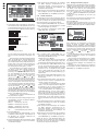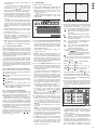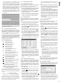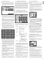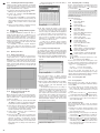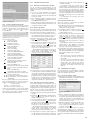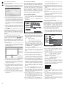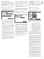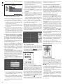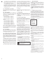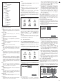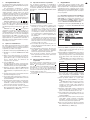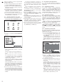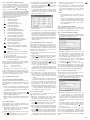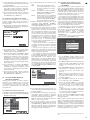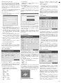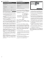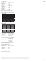
1
18 Video outputs as BNC jacks to connect monitors
2
19 DMR-180 / DMR-184:
audio inputs AIN 1 – 4 for the channels CH 1 – 4
as RCA jacks to connect the audio outputs of
cameras with microphones;
DMR-188 only has one audio input which can be
assigned to the desired video input in the setting
menu
The units (video recorder and power supply unit)
correspond to all required directives of the EU and
are therefore marked with .
20 Audio outputs as RCA jacks, e. g. to connect the
audio inputs of monitors
21 USB port
to connect the mouse provided
22 USB port
to connect an external storage
medium (USB stick or hard disk) for data backup
or for processing the video recordings
23 Jack LAN to connect a computer network (Ethernet) for remote control via a computer
WARNING The power supply unit uses dangerous mains voltage. Leave servicing to
skilled personnel only. Inexpert handling or modification of the unit may
result in electric shock.
Please observe the following items in any case:
G
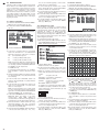
SENSOR 1 – 4 (DMR-188: Sensor 1 – 8):
connections for sensors triggering an alarm (e. g.
motion detectors; chapter 10.1)
Do not place any vessel filled with liquid on the
units, e. g. a drinking glass.
G
The heat generated within the video recorder must
be dissipated by air circulation. Therefore, the air
vents of the housing must not be covered.
G
ALARM:
output for units processing an alarm (e. g. signal
devices)
25 Jack VGA to connect a computer monitor with
VGA input
26 Jack DC 12 V for power supply via the power
supply unit provided and connected to 100 – 240 V~ /
50 – 60 Hz
1.3
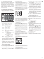
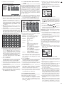
30 Button AUDIO / SEARCH without function
31 Buttons for the recorder functions:
start or continuation of replay
interruption of replay (PAUSE), sequential
frames (FRAME); activation / deactivation of
the sequence function
replay at 2-fold, 4-fold or 8-fold forward
speed
replay at 2-fold, 4-fold or 8-fold reverse
speed
manual start of a recording
end of replay or of a recording started manually
– USB 2.0 interface for exporting video files
– RS-485 interface for remote control of suitable
cameras (PTZ)
– LAN interface for connection to a computer network / to the Internet
– remote access for live surveillance, replay of
recordings and configuration of the recorder
via LAN / Internet by computer or mobile phone
with the software provided or Windows Internet
Explorer
– recording, live surveillance and remote access
possible at the same time
– replay of exported recordings via software provided
4
Installing a Hard Disk
To make video recordings, install a hard disk (connection type SATA, 1 TB max.) first. DMR-180 is
supplied with a 250 GB hard disk already installed
which may also be replaced by a 1 TB hard disk, if
required. To install the hard disk:
2) Release the screws fixing the cover of the housing, then remove the cover.
G
No guarantee claims for the units and no liability
for any resulting personal damage or material
damage will be accepted if the units are used for
other purposes than originally intended, if they are
not correctly connected or operated, or if they are
not repaired in an expert way. Likewise, no liability
will be accepted for operating errors or for data
loss caused by a defect and for consequential
damage of this data loss.
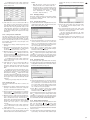
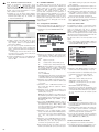
3) Connect the plugs of the power supply cable (a)
and of the data cable (b) to the contacts of the
hard disk according to figure 7.
If the units are to be put out of operation
definitively, take them to a local recycling
plant for a disposal which will not be harmful to the environment.
3
Applications
The digital video recorders DMR-180, DMR-184 and
DMR-188 are specially designed for applications in
video surveillance systems. Recordings of up to 4
(DMR-180 and DMR-184) or 8 (DMR-188) camera
signals are made on a hard disk of 1 TB max.
according to the highly efficient H.264 compression
procedure. DMR-180 is already equipped with a
250 GB hard disk and is supplied with two cameras
with infrared LEDs and connection cables in the set
DMR-180SET.
The features of the recorder include, among others:
1) Disconnect the recorder from the power supply.
4) Fasten the hard disk to the supporting rails via
two screws each on the right and left sides.
5) Replace the cover of the housing and fasten the
screws again.
5
Connecting Units
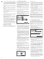
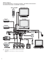
Figures 69 and 70 on the last pages of the instruction manual show an example for connection each
for DMR-180 or DMR-184 and DMR-188; however,
it will not be necessary to use all of the connection
possibilities shown.
Switch off the recorder before connecting any
units or changing any existing connections.
5.1
Video connections
1) Connect the video outputs of the cameras to the
jacks CH 1 – CH 4 or CH 1 – CH 8 (17).
2) Connect the video input of a monitor to one of the
two jacks VIDEO OUTPUT (18) and / or connect a
computer monitor with VGA input to the jack VGA
(25). The second jack VIDEO OUTPUT (18)
allows to connect another monitor or, for example, another video recorder.
– 3 recording qualities
– audio recording for 4 channels (DMR-180 and
DMR-184) or 1 channel (DMR-188)
– 4 recording modes: started manually, time-controlled, triggered by external alarm signal or by the
internal motion detector
33 Button SEL to activate the menu list or a submenu and to confirm a selection or input
– image corrections to be adjusted separately for
each camera channel
34 Button MUTE without function
– video motion detector to be configured differently
for each camera channel
36 Battery compartment cover
– alarm triggering via motion detection, via external
alarm signal, in case of video signal loss or if hard
disk is full or missing
For cleaning only use a dry, soft cloth; never use
water or chemicals.
32 Button MENU to activate / deactivate the main
menu, to deactivate submenus or an input field
35 Battery compartment latch
– 4 (DMR-180 and DMR-184) or 8 (DMR-188) alarm
inputs, 1 alarm output
G
DMR-188:
to change from full image display of a channel to
the display of several channels; each time the
button is pressed, the view will switch between
the quadrant display of the channels CH 1 to
CH 4, CH 5 to CH 8 and the simultaneous display
of all eight channels
GB
– infrared remote control
Never pull the mains cable for disconnecting the
mains plug from the socket, always seize the plug.
28 DMR-180 / DMR-184:
button ALL to change from full image display of a
channel to the quadrant display of all channels
29 Buttons , ,
and
to select a menu item,
an input field, a list entry, an inserting position or
a button
Do not operate the units and immediately disconnect the mains plug of the power supply unit from
the socket
1. if one of the units or the mains cable is visibly
damaged,
2. if a defect might have occurred after a unit was
dropped or suffered a similar accident,
3. if malfunctions occur.
In any case the units must be repaired by skilled
personnel.
– easy operation via mouse control (mouse provided)
G
Infrared remote control
27 Buttons 0 – 9 to display the corresponding channel (CH 1 to CH 4 or for DMR-188: CH 1 to CH 8)
as a full image; in the setting menu, to enter numbers
The units are suitable for indoor use only. Protect
them against dripping water and splash water,
high air humidity and heat (admissible ambient
temperature range 0 – 40 °C).
G
24 Terminals
RS485 + / -:
data bus for PTZ control of cameras ( chapter 11)
Safety Notes
– 2-stage password protection against unauthorized
operation
– 2 video outputs and 1 VGA output, 2 audio outputs
(DMR-180, DMR-184) or 1 audio output (DMR188)
– camera signals to be reproduced individually as a
full image or simultaneously with a split screen
– video system to be selected: PAL / NTSC
5.2
Audio connections
1) For audio recordings and / or live surveillance, the
RCA input jacks AIN1 – AIN4 (19) allow to connect, for example, the audio outputs of cameras
with integrated microphones or the preamplifiers
of microphones set up separately. DMR-188 only
offers one AUDIO INPUT (19). This input may be
assigned to any desired video input for recording
( chapter 8.1).
2) For audio replay, the mono signal of the channel
currently displayed will be available at both RCA
output jacks AUDIO OUTPUT (20). If several
channels are displayed at the same time, the
sound of the last channel shown as a full image
will be replayed.
For DMR-188, there will be an audio signal at
the jack AUDIO OUTPUT (20) if the channel
assigned is displayed or was the last channel
selected as a full image.
23