1
AlterPath KVM/net Installation,
Administration, and User’s Guide
Software Version 2.1.1
Cyclades Corporation
3541 Gateway Boulevard
Fremont, CA 94538 USA
1.888.CYCLADES (292.5233)
1.510.771.6100
1.510.771.6200 (fax)
http://www.cyclades.com
Release Date: May 2006
Part Number: PAC0368
©2006 Cyclades Corporation
Information in this document is subject to change without notice.
The following are registered or registration-pending trademarks of Cyclades Corporation in the United
States and other countries: Cyclades and AlterPath.
All trademarks, trade names, logos and service marks referenced herein, even when not specifically
marked as such, belong to their respective companies and are not to be considered unprotected by law.
Contents
Before You Begin ................................................... xiii
Chapter 1: Introduction ............................................. 1
Description ...................................................................................................... 2
Guidelines for Using the KVM/net ................................................................. 4
Connectors on the KVM/net ........................................................................... 4
Types of Ports ............................................................................................. 4
Connectors on the Back .............................................................................. 6
Power Connector and Power Switch ....................................................... 7
KVM Ports .............................................................................................. 7
Management Ports (Console, Ethernet, User 1, User 2) ......................... 8
AUX Ports ............................................................................................. 10
Activity LEDs on the Back of the KVM/net ................................................ 10
AlterPath KVM/net Ordering Options .......................................................... 13
Types of Users .............................................................................................. 14
Simultaneous KVM/net Logins ................................................................ 15
Simultaneous Server Connections ............................................................ 16
Administration Options ................................................................................. 17
Cyclades Web Manager ................................................................................ 18
Prerequisites for Using the Web Manager .................................................... 19
TCP Ports ...................................................................................................... 20
Cascaded Devices ......................................................................................... 21
Accessing Ports on Cascaded KVM Devices ........................................... 24
KVM/net Port Permissions ....................................................................... 24
Understanding KVM Port Permissions ..................................................... 25
KVM Port Permissions Hierarchy ............................................................ 26
Decision 1: Check User’s KVM Port Permissions ............................... 26
Decision 2: Check Group’s KVM Port Permissions ............................. 27
Decision 3: Check Generic User’s KVM Port Permissions .................. 27
Decision 4: Check User’s Default Permissions .................................... 28
Decision 5: Check Group’s Default Permissions .................................. 28
Decision 6: Check Generic User’s Default Permissions ....................... 29
Server Access: Inband and Out of Band ....................................................... 29
Determining the Connection Type and its Supported Functionality ........ 31
Administering Users of Connected Servers .................................................. 33
Types of Access to Ports ........................................................................... 33
Tasks Related to Access to Connected Devices ....................................... 33
Redefining Keyboard Shortcuts (Hot Keys) ................................................. 35
Redefining KVM Connection Hot Keys ................................................... 35
Redefining Sun Keyboard Equivalent Hot Keys ...................................... 35
Summary of Tasks for Redefining Hot Keys ............................................ 36
Disabling Mouse Acceleration ...................................................................... 36
Screen Resolution and Refresh Rate ............................................................. 37
Packet Filtering on the KVM/net .............................................................. 38
Power Management ...................................................................................... 40
Options for Managing Power .................................................................... 40
Controlling Power Through the Web Manager IPDU Power Management
Forms .................................................................................................... 41
Controlling Power While Connected to KVM Ports ............................ 41
Setting Up and Configuring Power Management ..................................... 42
Security ......................................................................................................... 44
Security Profiles ........................................................................................ 44
Encryption ................................................................................................. 45
Authentication ........................................................................................... 45
Choosing Among Authentication Methods .......................................... 45
Tools for Specifying Authentication Methods ...................................... 48
Lockout Macro .......................................................................................... 49
Notifications, Alarms, and Data Buffering ................................................... 53
Syslog Servers ........................................................................................... 54
Prerequisites for Logging to Syslog Servers ......................................... 54
Facility Numbers for Syslog Messages ................................................. 54
Example of Using Facility Numbers ..................................................... 54
SNMP Traps .............................................................................................. 55
Configuring Logging, Alarms, and SNMP Traps ..................................... 55
VPN and the KVM/net ................................................................................. 56
iv
AlterPath KVM/net Installation, Administration, and User’s Guide
Considerations When Choosing Whether to Enable DHCP ......................... 57
KVM Terminator Usage and Types .............................................................. 58
Activity LEDs on the Terminator ............................................................. 58
KVM Expander ............................................................................................. 59
KVM Expander Features .......................................................................... 59
KVM Expander Models and Components ................................................ 60
Ports on the KVM Expander ..................................................................... 62
LEDs on the KVM Expander .................................................................... 63
Power Outlets on the KVM Expander ...................................................... 63
Cascading a KVM Expander .................................................................... 64
Adding the KVM Expander to the KVM/net Unit’s List
of Cascaded Devices ................................................................................. 67
Upgrading the Microcontroller Code ........................................................ 67
User Access ............................................................................................... 68
AlterPath KVM RP ....................................................................................... 68
Connectors on the Back of the KVM RP .................................................. 69
Chapter 2: Installation ............................................. 71
Shipping Box Contents KVM/net ................................................................. 73
Setting Up the KVM/net ............................................................................... 75
Making an Ethernet Connection ................................................................... 77
Connecting Servers to the KVM Ports ......................................................... 78
Making a Direct Connection for Network Configuration ............................. 82
Powering On the KVM/net and Connected Devices .................................... 83
Performing Basic Network Configuration .................................................... 84
Configuring Basic Networking Using the wiz Command ........................ 85
Configuring Basic Networking Using the OSD ........................................ 89
Completing Configuration Using the Web Manager .................................... 98
Changing Default Passwords ........................................................................ 99
Enabling Access to the Web Manager without Making a Direct Connection ..
..................................................................................................................... 101
Preconfiguring the KVM/net for Remote Installation ................................ 104
Additional Configuration Tasks .................................................................. 105
Disabling Mouse Acceleration ................................................................... 106
Required Security Settings For Internet Explorer ....................................... 109
Modify IE Security Settings .................................................................... 109
v
Chapter 3: Advanced Installation Procedures .... 115
Connecting an External Modem ................................................................. 116
Connecting AlterPath PMs to the KVM/net ............................................... 117
Installing the AlterPath KVM Expander .................................................... 119
Shipping Box Contents KVM Expander ................................................. 120
Setting Up the KVM Expander ............................................................... 121
Powering On the KVM Expander and Connected Devices .................... 124
Connecting Cascaded KVM Units to the Primary KVM/net ..................... 126
Installing the AlterPath KVM RP ............................................................... 129
Shipping Box Contents AlterPath KVM RP ........................................... 130
Options for Accessing the KVM RP ....................................................... 131
Supplying Power to the KVM RP ........................................................... 132
Chapter 4: Web Manager for Administrators ...... 133
Common Tasks ........................................................................................... 134
Common Features of Administrators’ Windows ........................................ 136
Administrators’ Control Buttons, Logout Button, and KVM/net Information
.................................................................................................................. 136
Obtaining More Information ................................................................... 137
Logging In to the Web Manager and Saving Changes ........................... 137
Administrative Modes ................................................................................. 141
Wizard Mode .............................................................................................. 141
Procedures in Wizard Mode .................................................................... 142
Steps in Wizard Mode [Wizard] ............................................................. 143
Step 1: Security Profile [Wizard] ............................................................ 143
Pre-defined Security Profiles .............................................................. 143
Custom Security Profile ...................................................................... 144
Step 2: Network Settings [Wizard] ......................................................... 149
Step 3: Access [Wizard] .......................................................................... 151
Step 4: System Log [Wizard] .................................................................. 157
Expert Mode .............................................................................................. 159
Access ......................................................................................................... 160
Connect to Server .................................................................................... 161
IPDU Power Management ...................................................................... 161
Outlets Manager .................................................................................. 162
View IPDUs Info ................................................................................ 164
Users Manager .................................................................................... 165
vi
AlterPath KVM/net Installation, Administration, and User’s Guide
Configuration ...................................................................................... 167
Software Upgrade ............................................................................... 169
Configuration .............................................................................................. 169
KVM ....................................................................................................... 170
General ................................................................................................ 171
General ................................................................................................ 172
Enabling Direct Access to KVM Ports ............................................... 173
Redefining KVM Connection Keyboard Shortcuts (Hot Keys) ......... 173
Redefining Sun Keyboard Modifier Keys .......................................... 175
Specifying Authentication for KVM Port Logins ............................... 175
Local Users and IP Users .................................................................... 176
Devices ................................................................................................ 182
Configuring Individual KVM Ports .................................................... 183
Configuring Cascaded KVM Units ..................................................... 187
Users & Groups ................................................................................... 191
Configuring Inband (RDP) Servers ........................................................ 199
Prerequisites for Inband Access to RDP Servers .................................... 200
Security ................................................................................................... 204
Configuring an Authentication Method .............................................. 205
Configuring Authentication Servers for Logins to the KVM/net and
Connected Devices .............................................................................. 208
Group Authorization ........................................................................... 209
Group Authorization on TACACS+ ................................................... 220
Security Profiles ...................................................................................... 221
Pre-defined Security Profiles .............................................................. 221
Custom Security Profile ...................................................................... 222
Network ................................................................................................... 226
Host Settings ....................................................................................... 228
Syslog .................................................................................................. 231
IP Filtering .......................................................................................... 233
VPN ..................................................................................................... 250
SNMP .................................................................................................. 253
Notifications ........................................................................................ 258
Host Tables ......................................................................................... 262
Static Routes ....................................................................................... 264
AUX Port ................................................................................................ 266
System ..................................................................................................... 268
Time/Date ........................................................................................... 269
vii
Setting up Customized Timezone Configuration ................................ 271
Boot Configuration ............................................................................. 273
Online Help ............................................................................................. 277
Viewing System Information ...................................................................... 278
General .................................................................................................... 278
Station Status .......................................................................................... 279
Management ................................................................................................ 281
Backup Configuration ............................................................................. 283
Firmware Upgrade .................................................................................. 287
Microcode Upgrade ................................................................................ 290
Microcode Reset ..................................................................................... 294
Active Sessions ....................................................................................... 296
Reboot ..................................................................................................... 298
Chapter 5: Web Manager for Regular Users........ 299
Web Manager for Regular Users ................................................................ 300
Prerequisites for Logging in to the Web Manager ...................................... 302
Connect to Server ........................................................................................ 304
IPDU Power Management .......................................................................... 304
Power Control of Any Device Plugged Into an AlterPath PM on the KVM/
net ............................................................................................................ 305
Changing Your KVM/net Password ........................................................... 306
Chapter 6: Accessing Connected Devices .......... 307
Who Can Access Connected Devices ......................................................... 309
Server Connections: What You See ............................................................ 310
Viewing KVM Connections ................................................................... 311
Viewing In-band Connections ................................................................ 313
Prerequisites for Accessing Servers With In-band Connections ................ 313
Prerequisites for Accessing Servers With KVM Connections ................... 314
Disabling Mouse Acceleration .................................................................... 314
Screen Resolution and Refresh Rate ........................................................... 315
Web Manager Login Screen ....................................................................... 316
Login Screen: Direct Logins Not Enabled .............................................. 318
Connect to Server Drop-down List ......................................................... 318
Servers and Connection Types in the Connect to Server Drop-down List
viii
AlterPath KVM/net Installation, Administration, and User’s Guide
.............................................................................................................. 318
Port Numbers of Cascaded KVM Devices in the Connect to Server Dropdown List ............................................................................................ 319
Login Screen: Direct Logins Enabled, Only IP Address Entered ........... 320
Login Screen: Direct Logins Enabled, IP Address and Port Entered ..... 320
Connecting to Servers Remotely Through the Web Manager .................... 321
Connecting to Servers Locally Through the OSD ...................................... 325
Controlling KVM Port Connections ........................................................... 328
Hot Keys for KVM Connections ............................................................ 329
Hot Keys for Emulating Sun Keyboard Keys ......................................... 330
Cycling Between Servers ........................................................................ 332
Resetting the Keyboard and Mouse ........................................................ 334
Controlling Power of a KVM-connected Server .................................... 335
Closing a KVM Connection .................................................................... 336
Sharing KVM Port Connections ............................................................. 336
AlterPath Viewer Settings .......................................................................... 339
Recommended Settings ........................................................................... 339
Options Menu .......................................................................................... 340
Setting the Viewer Options ..................................................................... 341
Connection Menu .................................................................................... 342
Power Management .................................................................................... 343
Modem Connections ................................................................................... 346
Chapter 7: On Screen Display .............................. 351
Navigating the OSD .................................................................................... 352
Basic Navigation Keys ............................................................................ 352
Common Navigation Actions ................................................................. 353
Logging In Through the OSD ..................................................................... 353
OSD Main Menu ......................................................................................... 354
Invoking OSD Using [PrintScreen] Key .................................................... 355
Connection Menu ........................................................................................ 356
Power Management Menu .......................................................................... 357
Configure Menu Overview ......................................................................... 358
Understanding OSD Configuration Screen Series .................................. 361
General Configuration Screens [OSD] ................................................... 362
Network Configuration Menu Options [OSD] ....................................... 365
Network Configuration Screens [OSD] .............................................. 366
ix
SNMP Configuration Screens [OSD] ................................................. 369
VPN Configuration Screens [OSD] .................................................... 373
IP Filtering Configuration Screens ..................................................... 377
Hosts Configuration Screens [OSD] ................................................... 384
Static Routes Configuration Screens .................................................. 386
Date/time Configuration Screens ............................................................ 389
User Station Screens ............................................................................... 390
KVM Ports Screens ................................................................................. 394
AUX Port Screens ................................................................................... 396
Cascade Devices ..................................................................................... 399
Users and Groups Screens ...................................................................... 403
Syslog Screens ........................................................................................ 410
Notification Screens ................................................................................ 411
Authentication Screens ........................................................................... 413
Save/Load Configuration Screens ........................................................... 421
System Info Menu ....................................................................................... 424
Reboot ......................................................................................................... 426
Controlling the OSD Through the AlterPath KVM RP .............................. 428
Appendix A: Troubleshooting .............................. 431
How to Replace the KVM/net’s Boot Image .......................................... 431
How to Upgrade the Firmware on KVM/net .......................................... 437
How to Boot the KVM/net Over the Network. ....................................... 440
How to Boot the KVM/net in Single User Mode ................................... 442
How to Disable Mouse Acceleration Using Windows Registry ............. 445
Appendix B: Technical Specifications................. 447
Appendix C: Safety Guidelines............................. 449
General Safety Precautions ......................................................................... 449
Rack or Cabinet Placement ......................................................................... 451
Table Placement .......................................................................................... 451
Safety Guidelines for Rack-Mounting the KVM/net .................................. 451
Safety Precautions for Operating the AlterPath KVM/net ......................... 453
x
AlterPath KVM/net Installation, Administration, and User’s Guide
Glossary ................................................................. 457
Index ....................................................................... 471
xi
xii
AlterPath KVM/net Installation, Administration, and User’s Guide
Before You Begin
This installation, administration, and user’s guide provides background
information and procedures for installing, configuring, and administering the
Cyclades™ AlterPath family of KVM products including:
• AlterPath KVM/net
• AlterPath KVM Expander
• AlterPath KVM RP
• AlterPath KVM Terminators
In addition, this guide offers information and procedures for accessing
connected servers and other connected devices.
Audience
This manual is intended for installers and system administrators of the
AlterPath KVM/net and for users who may be authorized to connect to
devices and to manage power through the AlterPath KVM/net.
This document describes configuration, administration, and use of the
AlterPath KVM/net only. It does not describe how to set up and administer
other external services or servers that the AlterPath KVM/net may access for
authentication, system logging, SNMP notifications, data logging, file
sharing, or other purposes. This document assumes that users who are
authorized to connect to servers and other devices through the AlterPath
KVM/net already know how to use the connected devices.
Document Organization
This document contains the following chapters:
Chapter 1: Introduction
Defines and explains the overall product
features and uses of AlterPath KVM/net.
Chapter 2: Installation
Explains the procedures for installing the
AlterPath KVM/net and setting up its basic
configuration.
Chapter 3: Advanced Installation
Procedures
Explains the procedures for installing the KVM
Expander and the KVM RP in addition to
explaining how to install an external modem,
an AlterPath PM and how to cascade KVM
units to the AlterPath KVM/net.
Chapter 4: Web Manager for
Administrators
Explains how to use the Web Manager,
highlighting such procedures as how to
configure the AlterPath KVM/net, add or delete
users, define user access, add or delete server
connections, and other topics pertaining to
AlterPath KVM/net administration.
Chapter 5: Web Manager for Regular
Users
Presents the procedures for connecting to a port
and other operations related to using the web
user interface.
Chapter 6: Accessing Connected
Devices
Explains how to connect to KVM ports and
inband servers and how to use the AlterPath
Viewer and control KVM connection sessions.
Chapter 7: On Screen Display
Describes how to use the On Screen display for
local connections to the User 1 port.
Appendix A: Troubleshooting
Explains how to troubleshoot
commonAlterPath KVM/net issues.
Appendix B: Technical Specifications
List the technical specifications for the KVM/
net
xiv
AlterPath KVM/net Installation, Administration, and User’s Guide
Appendix C: Safety Guidelines
List the general safety guidelines for Cyclades
products.
Glossary
Glossary of terms and acronyms used in the
manual.
Related Documents
The following document for the AlterPath KVM/net is shipped with the
product.
• AlterPath KVM/net QuickStart Guide (hard-copy)
The documentation for Cyclades AlterPath products mentioned in this guide
such as AlterPath PM, and AlterPath KVM family of products are on the
Documentation CD shipped with the product and they are also available at:
http://www.cyclades.com/support/downloads.php.
Updated versions of this document will be posted on the downloads section of
the Cyclades website in the “AlterPath KVM/net” section when Cyclades
releases new versions of the software.
A printed version of this document can be ordered under part number
PAC0368through your Cyclades sales representative.
Typographic and Other Conventions
The following table describes the typographic conventions used in Cyclades
manuals.
Table P-1: Typographic Conventions
Typeface
Meaning
Example
Links
Hypertext links or URLs
Go to:
http://www.cyclades.com
xv
Table P-1: Typographic Conventions
Typeface
Meaning
Example
Emphasis
Titles or emphasized or new words or
terms
See the AlterPath KVM/net
Quick Start
Filename or
Command
Names of commands, files, and
directories; onscreen computer output.
Edit the pslave.conf
file.
User type
What you type in an example, compared
to what the computer displays
[kvm #] ifconfig eth0
The following table describes other terms and conventions.
Table P-2: Other Terms and Conventions
Term or Convention
Meaning
Examples
Hot keys
When hot keys are shown, a plus
(+) appears between two keys
that must be pressed at the same
time, and a space appears
between two keys that must be
pressed sequentially.
Ctrl+k p entered while
the user is connected to a
KVM port brings up an
IPDU power management
screen. Ctrl and k must be
pressed at the same time
followed by p.
Navigation shortcuts
Shortcuts use the “greater than”
symbol (>) to indicate how to
navigate to Web Manager forms
or OSD screens.
Go to Configuration>KVM>
General in Expert mode.
xvi
AlterPath KVM/net Installation, Administration, and User’s Guide
Chapter 1
Introduction
This chapter gives an overview of the features of the Cyclades AlterPath
KVM/net. This chapter describes how administrators and operators can use
the KVM/net features to securely manage connected computer systems and a
large variety of devices from anywhere on the local area network or on the
Internet. This chapter also provides important prerequisite information for
understanding the information and procedures in this manual.
The following table lists the topics in this chapter.
Description
Page 2
Connectors on the KVM/net
Page 4
Cyclades Web Manager
Page 18
Prerequisites for Using the Web Manager
Page 19
Cyclades Web Manager
Page 18
Accessing Ports on Cascaded KVM Devices
Page 24
TCP Ports
Page 20
AlterPath KVM/net Ordering Options
Page 13
Administering Users of Connected Servers
Page 33
Power Management
Page 40
Notifications, Alarms, and Data Buffering
Page 53
Considerations When Choosing Whether to Enable DHCP
Page 57
Description
KVM Terminator Usage and Types
Page 58
Description
The KVM/net is a 1U rack-mountble device that serves as a single access
point for administering and using servers and other devices through inband
and out-of-band access methods.
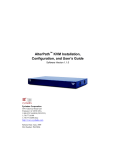
The following figure shows the front and back of the KVM/net.
Figure 1-1: KVM/net Front and Back
You use the KVM ports on the left and middle back of the KVM/net to
connect servers. You can use the AUX port on the right back to connect
AlterPath PMs or an optional external modem. You use the management ports
on the right back to connect to the KVM/net and to its connected devices.
Depending on the model, the KVM/net comes with either 16- or 32-KVM
ports to connect from 16 to 32 servers with KVM connections.
The KVM/net can be used to manage power of up to 128 devices when the
devices are plugged into up to 32 daisy-chained AlterPath PM intelligent
power distribution units that are connected to the AUX port on the KVM/net.
KVM/net administrators and users who are authorized to access connected
devices can connect locally or remotely from LANs, WANs, or other dial-in
connections through the Ethernet port or through an optional external modem.
For extended local administration, administrators can connect the Cyclades
AlterPath KVM Expander (purchased separately) to the KVM/net with a
CAT5 cable of up to 500 feet in length.
2
AlterPath KVM/net Installation, Administration, and User’s Guide
Description
Note: The 500-foot limit includes the distance of the User 2 from the KVM/net and
the distance of the most remote system connected to a KVM port.
Secondary KVM units such as the Cyclades AlterPath KVM Expander or an
AlterPath KVM can be cascaded for extended KVM server connections. A
maximum of 32 secondary KVM devices can be cascaded from the primary
KVM/net extending the number of KVM ports to a maximum of 512 for twouser configuration (i.e. two connections to each cascaded device), or 1024 for
a one-user configuration.
If multiple KVM/net units are installed in multiple remote locations, a
Cyclades AlterPath Manager (purchased separately) can manage all the
KVM/net units together with other Cyclades products and their connected
devices through a single IP address.
Access to the KVM/net for administration is separate from access to
connected devices. Only the KVM/net administrator can configure access to
the KVM/net and to the connected devices.
Both KVM/net administrators and users authorized to access connected
devices can use the Web Manager from a browser. Authorized users can log in
to devices, manage power, and change their own passwords, but they do not
have access to the KVM/net screens for configuring users or ports.
All logins to the KVM/net are subject to authentication. The KVM/net
administrator can restrict access to each of the connected devices by choosing
among authentication methods for logins to the KVM/net and to its ports.
Authentication can be local to the KVM/net or through an authentication
server.
The KVM/net administrator can further control access by controlling which
ports are assigned to each user name.
The KVM/net administrator can configure event logging, alarms, and
notifications, set up encryption, and data buffering.
After initial network configuration is performed on the KVM/net, the
Cyclades Web Manager provides a real-time view of all the connected
equipment and makes it possible for administration to be done from a browser
on any computer on site or on the Internet.
Introduction
3
Guidelines for Using the KVM/net
Guidelines for Using the KVM/net
Configuration of user accounts and access to the ports and all other
management of the connected devices is done through the Web Manager.
Troubleshooting in the event of network failure can be done using one of the
two direct-connect methods, or by using the Web Manager through a dial-up
connection to an external modem connected to the AUX port.
See “Accessing Connected Devices” on page 307 for instructions on how
users without KVM/net administration privileges can access computers and
AlterPath PMs that are connected to the KVM/net.
Connectors on the KVM/net
The following sections describe the connectors on the back and front of the
KVM/net, including ports, card slots, and plugs.
Types of Ports
The KVM/nets ports include KVM ports, which support server connections,
an AUX ports, and management ports including the User 1, User 2, Console,
and Ethernet ports, as described in the following table.
Table 1-1: Port Types
Port
Type
Connection Information
Where Documented
KVM
Connect an RJ-45 CAT5 cable to a
Terminator, which is connected to a
server.
• “KVM Ports” on page 7
• “To Connect Computers to KVM
Ports” on page 80
AUX
Connect an RJ-45 cable to an:
• “AUX Ports” on page 10
• “To Connect an AlterPath PM to
the AUX Port” on page 117
• “To Connect an External Modem
to the AUX Port” on page 116
• AlterPath PM intelligent power
distribution unit (IPDU)
or
• external modem.
4
AlterPath KVM/net Installation, Administration, and User’s Guide
Connectors on the KVM/net
Table 1-1: Port Types (Continued)
Port
Type
Connection Information
Where Documented
Console
Connect a CAT5 to DB-9 cable to a
COM port on a computer.
• “Management Ports (Console,
Ethernet, User 1, User 2)” on page
8
• “To Connect to the Console Port”
on page 82
Ethernet
Connect an Ethernet cable to the
local area network (LAN).
• “Management Ports (Console,
Ethernet, User 1, User 2)” on page
8
• “To Make an Ethernet Connection”
on page 77
User 1
[PS/2 and
VGA]
Connect a keyboard, video, mouse
cable to a local station’s keyboard,
monitor, and mouse.
• “Management Ports (Console,
Ethernet, User 1, User 2)” on page
8
• “To Connect to the User 1
Management Port” on page 83
User 2
Connect an RJ-45 cable of up to 500
feet to an AlterPath KVM RP. The
KVM RP can be ordered separately.
• “Management Ports (Console,
Ethernet, User 1, User 2)” on page
8
• “AlterPath KVM RP” on page 68
• “To Connect the KVM RP to the
KVM/net” on page 131
Note: The 500-foot limit includes
the distance of the User 2 from the
KVM/net and the distance of the
most remote system connected to a
KVM port.
Introduction
5
Connectors on the KVM/net
Connectors on the Back
The back of the KVM/net has KVM and management ports, a power cord
connector, a power switch, and an AUX port as illustrated in the following
figure.
KVM Ports
Power Cord Connector and Switch
Management and AUX Ports
Figure 1-2: KVM/net Back Panel
• On the left are the power connector and power switch and either 16- or 32KVM ports, which are used for connecting computing systems with KVM
connections.
See “Power Connector and Power Switch” on page 7 and “KVM Ports” on
page 7.
• On the right is the AUX port, which is used to connect to PMs or an
external modem, and the management ports, which are used for local
management of the KVM/net.
See “Management Ports (Console, Ethernet, User 1, User 2)” on page 8
and “AUX Ports” on page 10.
6
AlterPath KVM/net Installation, Administration, and User’s Guide
Connectors on the KVM/net
Power Connector and Power Switch
The following figure shows the power connector and power switch on the left
rear of a KVM/net.
Power Cord Connector
Power Switch
Figure 1-3: Power Connector on the Left Rear
The KVM/net is furnished with a power cord used to connect the power
connector to a power supply.
See “To Power On the KVM/net” on page 84 for instructions on supplying
power to the KVM/net.
KVM Ports
The following figure shows KVM (keyboard, video, mouse) ports on the
center rear of the KVM/net.
Figure 1-4: KVM Ports on the Center Rear
KVM ports provide remote access to the keyboard, monitor, and mouse of
PCs with USB or PS/2 connectors or Sun servers with USB connectors.
Connecting a computer to a KVM port allows use of a keyboard, video, and
mouse of a remote station as if it were the keyboard video and mouse on the
connected computer. KVM port connections, also called out-of-band
Introduction
7
Connectors on the KVM/net
connections give access to information that is otherwise inaccessible through
in-band network interfaces.
For example, BIOS access, POST, and boot messages are inaccessible through
in-band connections. In some cases, the in-band network interfaces are not
available after the system boot is completed (for example, after a Windows
Safe Mode boot) without the kind of access these KVM connections provide.
Each connected computing system is identified in the management software
by the port number to which it is connected. The administrator can assign a
descriptive alias to each port to identify the connected computer. For example,
if a Sun E10K server is connected to port 3, the administrator might define the
port’s alias to be “Sun E10K.”
Customers order one of three Terminator types for connecting each KVM port
to a computer. See “KVM Terminator Usage and Types” on page 58 for more
details.
See “To Connect Computers to KVM Ports” on page 80 for instructions on
connecting servers to KVM ports.
Management Ports (Console, Ethernet, User 1, User 2)
The following figure shows the management ports on the right back of the
KVM/net.
User 1 Port
VGA Port
[User 1]
PS/2 Ports
[User 1]
User 2 Port
Serial Port
Ethernet
Port
Console
Port
Figure 1-5: Management Ports
8
AlterPath KVM/net Installation, Administration, and User’s Guide
Connectors on the KVM/net
The following list describes the management ports on the right back of the
KVM/net.
• Console – Its RJ-45 connection can be connected by a CAT5 to DB-9
cable to a COM port on a computer. Administrators can use a terminal
emulation program to locally manage and troubleshoot the KVM/net. See
“To Connect to the Console Port” on page 82 and “Configuring Basic
Networking Using the wiz Command” on page 85 for more details.
• Ethernet – Use the Ethernet management port for connecting an Ethernet
cable for Intranet and Internet access. See “Making an Ethernet
Connection” on page 77 for instructions if needed.
• User 1 – The User 1 port includes two PS/2 ports and a VGA port, which
can be connected to a mouse, keyboard, and monitor. Once a local system
is connected to the User 1 port, administrators can use the OSD (On Screen
Display) interface to locally manage and use the KVM/net. See “To
Connect to the User 1 Management Port” on page 83 and Chapter 7: On
Screen Display for more details.
• User 2 – This port is used for extending the local administration by
connecting an RJ-45 cable of up to 500 feet to an AlterPath KVM RP. The
KVM RP can be ordered separately. Administrators can use the OSD (On
Screen Display) to locally manage and use the KVM/net without being in
the same room as the KVM/net. See “Installing the AlterPath KVM RP”
on page 129 and “Controlling the OSD Through the AlterPath KVM RP”
on page 428 for more details.
Introduction
9
Activity LEDs on the Back of the KVM/net
AUX Ports
The following figure shows the AUX port on the right back of the KVM/net.
AUX Port
Figure 1-6: AUX Ports
AUX – Serial port (RS-232) with RJ45 connector that can be used for the
following:
• Connecting to an optional AlterPath PM
Up to 32 PMs can be daisy-chained for a total of 120 outlets. See “Power
Management” on page 40 for background information of power
management and see “Connecting AlterPath PMs to the KVM/net” on
page 117 for installation instructions.
• Connecting to an optional external modem
See “Connecting an External Modem” on page 116
Activity LEDs on the Back of the KVM/net
The KVM/net comes with paired LEDs positioned on each side of the
following ports:
•
•
•
•
10
User 2
AUX
Ethernet
Console
AlterPath KVM/net Installation, Administration, and User’s Guide
Activity LEDs on the Back of the KVM/net
The following figure shows the position of the LEDs as they appear on the
back of the KVM/net. The LEDs are designed to monitor the interface
connections as described in Table 1-2, “LED Descriptions,” on page 12.
The diagram below shows a close up view of the LEDs on the back of the
KVM/net. The LEDS monitor the AUX ports, ETHERNET, and CONSOLE
ports as described in Table 1-2.
1
2
3
5
6
7
4
8
Figure 1-7: LEDs on the KVM/net Management Ports
Introduction
11
Activity LEDs on the Back of the KVM/net
The LED numbers in the tables below correspond to the numbers in the
previous figure.
Table 1-2: LED Descriptions
Number
Label
Function
Color/Status
1
VID
EN
Monitor KVM CAT5
video interface
Orange - Lights when an internallygenerated signal is used. This occurs
when the user is not connected to the
port and in the OSD, or when the user is
connected to a port, but a video signal is
not present from the server.
Green - Lights when the server's video
signal is used; this happens when the
server is presenting a valid signal.
2
SYN
Monitor KVM CAT5
video interface
Green - Lights when the user is
connected to port and a video signal is
detected and "synchronized". This
means that the KVM is presenting the
signal to the station.
Orange - Lights when the video signal
level is detected but not synchronized.
Typically, this takes a very short amount
of time (less than 1/3 second) for the
KVM to synchronize to the server's
video signal upon first connection.
5, 3
LK
Monitor RS-232 async
port status
• OFF – Indicates the port is not open.
• Orange – Lights when DTR (data
terminal ready) signal is on (when the
port is open).
4, 5
ACT
Monitor RS-232 async
activity
• OFF – Indicates no data activity.
• Green – Blinks when data is either
being received (RX) or transmitted
(TX).
12
AlterPath KVM/net Installation, Administration, and User’s Guide
AlterPath KVM/net Ordering Options
Table 1-2: LED Descriptions (Continued)
Number
Label
Function
Color/Status
5
LK/
ACT/
COL
Monitor Ethernet line
status
• OFF – Indicates either link is not up or
cable is not connected.
• Green – Lights solid when the link is
up and blinks when data activity
occurs, with frequency proportional to
traffic.
• Orange – Blinks when collisions occur
6
100
Monitor Ethernet speed
• Off – Indicates the link is 10baseT or
no link is active.
• Green – Steady when 100baseT link is
active.
7
CPU
Monitor CPU (software
operation)
• Green or Orange – Blinks when
software is running properly.
• Off or solid Green/Orange – During
boot up, software crash, etc.
8
GP/
HD
Monitor compact flash
(HD) or other (GP)
• Orange - Blinks when KVM/net is
accessing the compact flash after
bootup.
AlterPath KVM/net Ordering Options
Each AlterPath KVM/net comes with 16 or 32 KVM ports. The following
table lists the model and part numbers and number of KVM ports of each
KVM unit.
Table 1-3: AlterPath KVM/net Model Numbers and Port Options
Model Number
Introduction
Part Numbers
KVM Ports
AlterPath KVM 16
16
AlterPath KVM 32
32
13
Types of Users
Types of Users
The KVM/net support three types of users:
• Predefined administrators who can administer the KVM/net and its
connected devices
• Optionally added users who can act as administrators of the KVM/net and
its connected devices
• Optionally added users who can act as administrators of connected devices
or regular users.
As summarized in the following table, two accounts, root and admin, are
configured by default and cannot be deleted. The default “admin” account can
add regular user accounts to allow other users to act as administrators of
connected devices. An administrator can also choose to add regular users to
the “admin” group, which enables the regular users to perform KVM/net
administrative functions. The following table lists the responsibilities of each
type of user and provides the default password for each.
Table 1-4: User Types, Responsibilities, and Default Password
Username
Responsibilities
Default Password
root
Cannot be deleted. Only console logins
allowed. Runs the wiz command to do initial
network configuration, as described in
“Configuring Basic Networking Using the wiz
Command” on page 85. Access Privileges:
Full Read/Write/Delete.
cyclades
admin
Cannot be deleted. Has all access: through the
Web Manager in Wizard and Expert mode,
and through the OSD. Has full access to every
function of the Web Manager. Access
Privileges: Full Read/Write/Delete.
cyclades
14
AlterPath KVM/net Installation, Administration, and User’s Guide
Types of Users
Table 1-4: User Types, Responsibilities, and Default Password (Continued)
Username
Responsibilities
Default Password
administratively
assigned
User account configured by the administrator
to be able to access devices connected to the
ports of the KVM/net. Has access to the port
through the Web Manager and through the
OSD. Regular users can access and administer
only devices that are connected to ports to
which they are assigned. Default Access
Privileges for generic users: Read/Write only
for all ports. Administrators can restrict access
for individual users to Read only to specific
ports.
If an administrator assigns a regular user to
the “admin” group, that user can also perform
the same administrative functions on the Web
Manager as the “admin” user, as described
above.
administratively
assigned
Simultaneous KVM/net Logins
Only one KVM/net administrator can be logged in at a time. If a second
administrative user attempts to log in to the Web Manager, the following
prompt appears offering a choice of cancelling the attempt to log in or
terminating the other administrator’s login session.
Introduction
15
Types of Users
Figure 1-8: Simultaneous Administrator Login Prompt
Note: This feature applies to both Web Manager and OSD.
Simultaneous Server Connections
The KVM/net supports a maximum of 6 concurrent server connections. Up to
two connections are supported either locally or remotely over Ethernet. Up to
4 connections can be inband depending on whether a KVM-over-IP
connection is being made. The types of user connections that can be made are
explained below:
• Local users include:
• One local user at the KVM/net (User 1).
• One remote user at the AlterPath KVM RP location (User 2).
• IP users include:
• KVM – The KVM/net supports two KVM-over-IP connections.
• Inband – KVM/net supports up to four concurrent in-band connections
depending on the number of KVM-over-IP connections being made.
Since the maximum total IP connections is four, if one KVM-over-IP
connection is being made, only three in-band connections can be made at
that time.
16
AlterPath KVM/net Installation, Administration, and User’s Guide
Administration Options
The following table lists the number and types of server connections that can
be made over IP based on the number of local users connected to KVM ports.
Table 1-5: Number of Simultaneous Server Connections
Local Users
0
1
2
KVM-over-IP
2
1
-
Inband
2
3
4
Total
4
5
6
Administration Options
The following sections summarize the KVM/net administration options:
• “Cyclades Web Manager” on page 17
• “On-Screen Display” on page 18
• “Guidelines for Using the KVM/net” on page 4
The administrator options require different types of log in credentials. For
more information on which types of users can perform administrative tasks
and access administrative options, see “Types of Users” on page 14.
Table 1-6: Administration Options
Cyclades Web
Manager
The Web Manager is the primary means of configuring the KVM/net
and administering its connected devices.
• See “Prerequisites for Using the Web Manager” on page 19 for an
introduction that includes prerequisites for using the Web Manager
and explanations about how the different types of user accounts use
the Web Manager.
• See “Web Manager for Administrators” on page 133 for more
details about how KVM/net administrators use the Web Manager.
Introduction
17
Cyclades Web Manager
Table 1-6: Administration Options (Continued)
The On Screen Display (OSD) can be used locally from a keyboard,
monitor and mouse that is directly connected to the KVM/net. When
the monitor and the KVM/net are on, the OSD login screen appears on
the monitor.
On-Screen
Display
• See “To Connect to the User 1 Management Port” on page 83 for
instructions on how to make the hardware connection.
• See “On Screen Display” on page 351 for how KVM/net
administrators and regular users can use the OSD.
Linux
Commands
and KVM/netspecific
Commands
The KVM/net offers the following types of access allowing
administrators to log in and enter Linux commands and KVM/netspecific commands in a shell running on the KVM/net.
• A local administrator who has a direct connection to the console
port on the KVM/net, who is running a terminal or terminal
emulation program, and who knows the root password. The direct
login requires authentication using the root password. The default
shell defined for the root user is bash.
• A remote administrator who uses telnet or ssh to connect to the
KVM/net and log in as root.
See “To Connect to the Console Port” on page 82 and “Configuring
Basic Networking Using the wiz Command” on page 85.
Cyclades Web Manager
Administrators perform most tasks through the Cyclades Web Manager. The
Web Manager runs in a browser and provides a real-time view of all the
equipment that is connected to the KVM/net. The administrator or the regular
user who has administrative access can use the Web Manager to configure
users and ports, troubleshoot, maintain, cycle power, and reboot the connected
devices, either while on site or from a remote location. KVM/net also allows
regular users and administrators to use the Web Manager to access devices
that are connected to KVM ports.
18
AlterPath KVM/net Installation, Administration, and User’s Guide
Prerequisites for Using the Web Manager
Web Manager uses forms and dialog boxes (which are pop-up windows) to
receive data input. See also, “Prerequisites for Using the Web Manager” on
page 19.
Administrators, see “Web Manager for Administrators” on page 133. Regular
users, see “Web Manager for Regular Users” on page 299.
Prerequisites for Using the Web Manager
The prerequisites described in this section must be complete before anyone
can access the Web Manager. If you have questions about any of the following
prerequisites, contact your site’s system or network administrator.
• An administrator needs to define basic network parameters on the KVM/
net so the Web Manager can be launched over the network.
See “Configuring Basic Networking Using the wiz Command” on page 85
for instructions on how to define network parameters on the KVM/net.
The administrator also needs the following to be able to connect to the KVM/
net through the Web Manager:
• A networked Windows computer that has access to the network where the
KVM/net is installed.
• A supported browser. Internet Explorer 5 and above, Netscape 8, Mozilla,
and Firefox browsers are supported for configuration and management of
KVM/net. Internet Explorer, Netscape 8, and Mozilla are recommended
browsers for accessing servers through a KVM-over-IP session.
• The IP address of the KVM/net.
Entering the IP address of the KVM/net in the address field of one of the
supported browsers listed in Table 1-14 is the first step required to access
the Web Manager.
When DHCP is enabled, a device’s IP address may change each time the
KVM/net is booted up. Anyone wanting to access the KVM/net must find
out the currently assigned IP address. If DHCP is enabled and you do not
know how to find out the current IP address of the KVM/net, contact your
Introduction
19
TCP Ports
system administrator for help. For more information, see “Considerations
When Choosing Whether to Enable DHCP” on page 57.
• A user account defined on the Web Manager
By default, the admin has an account on the Web Manager. An
administrator can add regular user accounts to administer connected
devices using the Web Manager.
TCP Ports
The TCP port numbers for KVM ports are used by the AlterPath Viewer when
a user connects to a KVM port through the Web Manager. When a user
connects to a KVM port through the Web Manager, the AlterPath Viewer uses
port 5900. Depending on your KVM model up to four IP modules may be
available. Subsequent port numbers 5901, 5902, and 5903 are used to launch
additional AlterPath Viewer sessions . You can assign a different port number
or numbers through the OSD or the Web Manager. Do not assign reserved
TCP port numbers 1 through 1024.
Special circumstances may require KVM/net administrators to specify
alternative TCP port numbers other than the defaults. For example, the
firewall may block TCP port 5900 or 5901.
The following table provides links to procedures for changing default TCP
port numbers.
Table 1-7: Tasks: Configuring TCP Port Numbers
Task
Where Described
Change the TCP port number(s) assigned
to the AlterPath Viewer(s)
“To Configure IP User (KVM Over IP)
Sessions [Expert]” on page 180
Change the TCP port number(s) assigned
to inband connections
“To Add or Modify an inband (RDP) Server”
on page 201
20
AlterPath KVM/net Installation, Administration, and User’s Guide
Cascaded Devices
Cascaded Devices
The KVM/net supports cascading, which allows administrators to connect
secondary KVM units to a primary KVM/net. Cascading allows
administrators to increase the number of managed devices to up to 1024
servers with a centralized configuration and access interface.
A maximum of 32 secondary KVM devices can be cascaded from the primary
KVM/net extending the number of KVM ports to a maximum of 512 for twouser configuration (i.e. two connections to each cascaded device), or 1024 for
a one-user configuration.
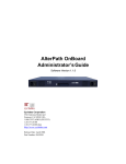
The following diagram depicts a basic cascaded configuration of a primary
KVM/net with 32 ports and one KVM and one KVM Expander cascaded from
it.
Introduction
21
Cascaded Devices
Up to 1024 servers
Sun Server
(Mini-DIN)
PC Server
(USB)
Sun Server
(Mini-DIN)
PC Server
(USB)
PC Server
(PS/2)
PC Server
(PS/2)
AlterPath KVM
Expander 16
AlterPath KVM 32
User1
User2 UserA UserB
Primary AlterPath KVM/net 32
local user
IP user
Figure 1-9: Cascaded KVM Devices from a KVM/net
As depicted in the previous figure, the KVM/net supports one level of
cascading: The primary KVM/net controls the secondary level of KVM units
connected to it. A secondary KVM unit can be a KVM, a KVM Expander, a
KVM/net, or a KVM/netPlus.
22
AlterPath KVM/net Installation, Administration, and User’s Guide
Cascaded Devices
Administrators can connect up to 32 KVM units to the master KVM/net. Each
cascaded KVM device has two management ports that can be connected to the
primary KVM/net.
Note: You must connect the master KVM/net’ KVM port to User 2 on the slave.
Optionally, you can add a second connection to User 1 on the slave by using a
terminator. If a KVM Expander is used then User A or User B management
ports on the KVM Expander can be used.
Note: In a cascaded configuration, the internal IP modules of the cascaded units are
not available.
The following table indicates which ports on each cascaded device can be
used for cascading and which cables need to be used in order to connect them.
Table 1-8: Connectors and Ports for Cascading KVM Units
KVM Unit
Management Ports
Connectors
KVM Expander
User B primary
CAT5 cable with RJ45
connectors
User A secondary
User 2 primary
CAT5 cable
User 1 secondary
KVM Terminator (User1)
and CAT5 cable with RJ45
connectors
AlterPath
KVM/net
User 2 primary
CAT5 cable
User 1 secondary
KVM Terminator (User1)
and CAT5 cable with RJ45
connectors
AlterPath
KVM/netPlus
User 2 primary
CAT5 cable
User 1 secondary
KVM Terminator (User1)
and CAT5 cable with RJ45
connectors
AlterPath KVM
Introduction
23
Cascaded Devices
Note: In addition to a CAT5 cable, you need a KVM Terminator to connect to the
User 1 port of a cascaded KVM, KVM/net, or KVM/netPlus.
KVM/net users can use the master KVM/net to access all devices connected
to KVM ports on the master and slave KVM units.
Accessing Ports on Cascaded KVM Devices
KVM/net users can use the master KVM/net to access all devices connected
to KVM ports on the master and slave KVM units. However, only two port
connections can be made to each cascaded unit at any time. Each physical port
connection (for example to User 1 or User B) to the cascaded KVM devices
allows a user to connect to one KVM port on the secondary KVM unit. So any
user can connect to up to two KVM ports on a cascaded device at any time.
KVM/net Port Permissions
In the default configuration, only the “admin” user can access any port. The
KVM/net administrator configures access for regular users as desired.
The following table summarizes the default port access permissions and
default authentication types (Auth Type) and provides links to where the port
permissions are described in more detail.
Table 1-9: Default Port Access Permissions
Default
Access
Default
Auth Type
Access Types
Where Documented
None
Local
No access
“Understanding KVM Port Permissions”
on page 25
Read only
Read/Write
“To Assign KVM Port Access to a User
or Group” on page 196
Full access (Read/
Write/Power
management)
24
AlterPath KVM/net Installation, Administration, and User’s Guide
Cascaded Devices
The KVM administrator must take the actions described under “Where
Documented” to allow any other types of access than the defaults defined in
the previous table. See “Authentication” on page 45 for the tasks related to
setting up authentication.
Understanding KVM Port Permissions
KVM port permissions are defined in the Web Manager by assigning Default
Permissions that apply to all KVM ports and by optionally assigning specific
permissions to individual ports or groups of ports. The options for “Default
Permissions” are shown in the following list.
•
•
•
•
No access [Default]
Read only
Read/Write
Full access (Read/Write/Power management)
For individual users and groups, if desired, the KVM/net administrator can
construct lists of KVM ports with the following types of permissions:
•
•
•
•
Ports with no permission
Ports with read only permission
Ports with read/write permission
Ports with full permission
A Generic User account has a default set of permissions that apply to all
regular users and groups. The Generic User’s Default Permission is “No
access.”
To allow users to access KVM ports, the KVM/net administrator must do one
or both of the following:
• Change the permissions assigned to the Generic User
• Change the permissions assigned to individual users or to groups of users
Editing the Generic User allows you to change the KVM port permissions for
all regular users and groups at once.
The KVM/net administrator can specify different Default Permissions or
KVM port permissions for any user or group. “KVM Port Permissions
Hierarchy” on page 26 provides information that the KVM/net administrator
Introduction
25
Cascaded Devices
needs to understand in order to perform advanced configuration of KVM
permissions.
The following table shows the tools that the KVM/net administrator can use to
set KVM port permissions and where in this manual to go for further details.
Table 1-10: Tools for Setting KVM Port Permissions
Tools
Where Documented
Web Manager
“To Assign KVM Port Access to a User or Group” on page 196
OSD
“KVM Ports Screens” on page 394
KVM Port Permissions Hierarchy
If you specify individual KVM port permissions or default permissions for
users and groups, you need to understand the following information about
how the system handles requests from a user who is trying to access a KVM
port. The following series of decisions is made.
Decision 1: Check User’s KVM Port Permissions
1. Does the user have specific KVM port permissions that allow or deny
access to the port?
• If yes, access is allowed or denied.
• If no, go to Decision 2.
Example for Decision 1
• If user john is trying to access KVM port 4 and his account has port 4 in
a list of ports with full permission, then john is given read/write and
power management access.
• If user jane is trying to access port 4 and her account has port 4 in a list of
ports with no permission, then jane is denied access.
• If users jim, joan, jerry, jill, joe, jennifer, jordan, jolanda, and jezebel are
trying to access port 4 and do not have port 4 listed for any types of
access, then their access requests are passed to decision 2.
26
AlterPath KVM/net Installation, Administration, and User’s Guide
Cascaded Devices
Decision 2: Check Group’s KVM Port Permissions
2. Is the user included in a group with KVM port permissions that allow or
deny access to the port?
• If yes, access is allowed or denied.
• If no, skip to Decision 3.
Note: When a user is in more than one group, the most restrictive permission is
used.
Example for Decision 2
• If user jim is trying to access port 4 and he is a member of a group called
linux_ca2 that has port 4 in a list of ports with read/write permissions,
then jim is given read/write access.
• If user joan is trying to access port 4 and she is in a group called
linux_ca3 that has port 4 in a list of ports with no permission, then joan is
denied access.
• If jerry and jill are trying to access port 4 and are in a group called
linux_ca4 that has no specific port permissions defined, then their access
requests are passed to decision 3.
• If joe, jennifer, jordan, jolanda, and jezebel are trying to access port 4 and
are not in any group, then their access requests are passed to decision 3.
Decision 3: Check Generic User’s KVM Port Permissions
3. Does the Generic User have specific KVM port permissions that allow or
deny access the port?
• If yes, access is allowed or denied.
• If no, go to decision 4.
Example for Decision 3
• If user jerry is trying to access port 4 and the Generic User has port 4 in a
list of ports with full access permissions, then jerry is given read writer
and power management access.
Introduction
27
Cascaded Devices
• If user jill is trying to access port 4 and the Generic User has port 4 in a
list of ports with no access permissions, then jill is denied access.
• If users joe, jennifer, jordan, jolanda, and jezebel are trying to access port
4 and the Generic User does not have port 4 listed for any type of access,
then their access request are passed to decision 4.
Decision 4: Check User’s Default Permissions
4. Does the user have a Default Permission that allows or denies access to the
port?
• If yes, access is allowed or denied.
• If the user has no Default Permission, the user is under the Generic
User’s default permission, and the request for access goes to decision 5.
Example for Decision 4
• If user joe is trying to access port 4 and he has a Default Permission that
allows read only access to ports, then joe is given read only access.
• If user jennifer is trying to access port 4 and she has a Default Permission
that allows no access to ports, then jennifer is denied access.
• If users jordan, jolanda, and jezebel are trying to access port 4 and their
Default Permissions are under the Generic User’s Default Permission,
then their access requests are passed to decision 5.
Decision 5: Check Group’s Default Permissions
5. Does the user belong to a group that has a Default Permission that allows or
denies access to the port?
• If yes, permission is granted or denied.
• If no, go to decision 6.
Example for Decision 4
• If user jordan trying to access port 4 is in a group called windows_ca1
that has a Default Permission of full, then jordan is given read/write and
power management access.
• If user jolanda trying to access port 4 is in a group called windows_ca2
that has a Default Permission of no access, then jolanda is denied access.
28
AlterPath KVM/net Installation, Administration, and User’s Guide
Server Access: Inband and Out of Band
• If user jennifer is not a member of any group with a Default Permission
specified, then her access request is passed to decision 6.
Decision 6: Check Generic User’s Default Permissions
Note: If an access request gets this far, the Default Permission of the Generic User is
the only permission that could apply.
6. Does the Default Permission for the Generic User allow access to the port?
• If yes, access is granted.
• If no, access is denied.
Server Access: Inband and Out of Band
KVM/net users can access servers over the Ethernet using the following
methods:
• In-band access – An IP address is used to connect to and control Windows
(Win2000, 2003, XP, and NT) Terminal Servers.
• Out-of-band access – KVM ports are used to connect to PCs with USB or
PS/2 connectors or Sun servers with USB connectors.
The differences between the in-band and out-of-band connection methods are
briefly described in the following table. For a more detailed description of the
requirements and functionality of each connection method, see the following
section, “Determining the Connection Type and its Supported Functionality”
on page 31.
Table 1-11: In-band and Out of Band Connections
Connection Type
Introduction
In-band
Out-of-Band
Remote Desktop Protocol
(RDP) over the Ethernet or PPP
Keyboard, video, mouse (KVM)
CAT5 connection to a KVM/net
and Ethernet or PPP access to
the KVM/net Web Manager
29
Server Access: Inband and Out of Band
Table 1-11: In-band and Out of Band Connections
In-band
Out-of-Band
Supported
Source
Computers
Client machine running a
Windows operating system with
a valid IP address
All Windows clients
Supported Target
Servers
Windows (Win2000, 2003, XP,
and NT) Terminal Servers
PCs with a USB or PS/2
connectors or Sun servers with
USB connectors
Supported
Browsers
Internet Explorer 5, 6
Internet Explorer 6, Netscape 7,
Mozilla, Firefox
Direct Log In
Not available
Available if configured by the
KVM/net administrator
See “To Enable Direct Access to
KVM Ports” on page 173.
Power
Management
While Connected
Not available
Available if configured by the
KVM/net administrator and if
the server is plugged into an
AlterPath PM that is connected
to the KVM/net.
See “Power Management” on
page 40.
Viewer
30
ActiveX viewer
AlterPath Viewer
See “Viewing In-band
Connections” on page 313
See “Viewing KVM
Connections” on page 311.
AlterPath KVM/net Installation, Administration, and User’s Guide
Server Access: Inband and Out of Band
Determining the Connection Type and its
Supported Functionality
When a user wants to connect to a server displayed on the Web Manager
Connect to Server form, the drop-down list indicates whether the server can
be accessed by a KVM connection, an in-band connection, or both. In the
connect list, all servers connected to KVM ports appear first followed by all
servers that are accessed through in-band connections and are not connected
to KVM ports; those servers that can be connected by both methods appear at
the bottom of the list.
The types of connections that can be made to each server is displayed in
parenthesis at the end of each server entry in the list. The following table
describes the functionality of each connection type.
Table 1-12: Available Functionality During KVM and In-band Connections
Server Connection
Labels
Description
(KVM)
Indicates that the server can be accessed only through an outof-band, KVM connection.
This server is connected to a KVM port on the KVM/net or on
a cascaded KVM unit.
Users can control all applications on the server, have BIOS
access, and can view POST, and boot messages. Users can
access this server even when the network is down or after a
system boot is completed.
Users can also control the power flow on this server if the
server is plugged into an AlterPath PM and the port is properly
configured for power management.
Introduction
31
Server Access: Inband and Out of Band
Table 1-12: Available Functionality During KVM and In-band Connections
Server Connection
Labels
Description
(In-band)
Indicates that the Microsoft Terminal Server running RDP can
be accessed only through an in-band connection and is not
connected to a KVM port.
Users can access this server only to run applications once the
server is already running. The performance on in-band
connections is slightly better than that of KVM connections,
and no synchronization of keyboard and mouse is necessary.
(KVM + In-band)
Indicates that the server can be accessed through In-band and
out-of-band (KVM) connections.
The first time users select this server from the Connect dropdown list, an in-band connection is attempted. The connection
automatically switches to KVM only if the in-band connection
fails or if an in-band connection to this server already exists.
Users who want to access this server with a KVM connection,
must do one of the following:
• Make two connection attempts to the same server from the
Web Manager Connect to Server form.
The first connection is an in-band connection viewed
through an RDP ActiveX viewer. The second connection is a
KVM connection viewed through the KVM ActiveX Viewer.
See “To Connect to Servers Through The Web Manager’s
“Connect To Server” Form” on page 322.
• Make a direct login to the KVM port.
See “Login Screen: Direct Logins Enabled, Only IP Address
Entered” on page 320 and “Login Screen: Direct Logins
Enabled, IP Address and Port Entered” on page 320 for more
information.
32
AlterPath KVM/net Installation, Administration, and User’s Guide
Administering Users of Connected Servers
Administering Users of Connected Servers
This section reviews the tasks that KVM/net administrators must do to enable
access to connected servers.
The “admin” account can add new regular user accounts to allow others to
connect to ports and administer or use connected devices.
Types of Access to Ports
The KVM/net administrator can restrict regular user accounts to allow them
only to manage specific servers and devices. Each account can have one of the
following types of access after login:
• Read only
• Read write
• Read write power
Note: The KVM/net offers access privileges to KVM ports only. Inband connections
are authenticated, and the access privileges are granted on the inband server
itself.
Tasks Related to Access to Connected Devices
Planning should include the following steps:
• Create a list of servers to connect to the KVM/net.
• Decide whether the servers need to be connected to ports for KVM access,
need to have RDP enabled for in-band access, or both.
• Create a list of user accounts with the type of access each user needs to
which ports.
• Obtain usernames and passwords with the proper permissions for
connected servers to give to the KVM/net users who will connect to these
servers.
• Create meaningful aliases to assign to port numbers and to inband
Windows Terminal Servers.
• List all the devices that need to be connected to PMs and the users who can
access them.
Introduction
33
Administering Users of Connected Servers
During setup of the KVM/net, the installer connects the desired servers to the
ports as planned.
During configuration, the KVM/net administrator does the following, if
desired:
• Assigns aliases to ports to identify the connected servers.
• Assigns aliases to PMs to identify the location or types of devices being
managed.
• Creates accounts for users of connected devices.
• Specifies which ports each user can access and which type of access each
can have.
• Specifies an authentication method for access to the KVM/net and to all
KVM ports.
• Redefines keyboard shortcuts (hot keys) if desired.
• Redefines TCP port numbers used for accessing KVM ports, if desired.
See the following table for a list of related tasks and where they are
documented.
Task
Where documented
Specify an alias for a KVM port.
• “To Specify or Change the Alias for a
KVM Port” on page 186
Specify an alias for a PM.
• “To Specify or Change the Alias of an
IPDU” on page 168
Assign permissions to access ports.
• “To Assign KVM Port Access to a User or
Group” on page 196
Assign permissions to PMs and outlets.
• “To Configure Users to Manage Specific
Power Outlets” on page 166
34
AlterPath KVM/net Installation, Administration, and User’s Guide
Redefining Keyboard Shortcuts (Hot Keys)
Redefining Keyboard Shortcuts (Hot Keys)
Predefined keyboard shortcuts (also called hot keys) allow users to do the
following:
• Perform common actions while connected through a KVM port
• Emulate Sun keyboard keys while connected through a KVM port to a Sun
server.
If desired, the KVM/net administrator can redefine the default hot keys either
through the Web Manager or the OSD.
Redefining KVM Connection Hot Keys
The hot key sequences used while connected to KVM ports have two parts,
which are called the common escape sequence and the command key. The
default common escape sequence is Ctrl+k, and the command key is
different for each command. For example, the q command key is entered after
Ctrl+k to quit the login session as shown here: Ctrl+k q. See “Hot Keys for
KVM Connections” on page 329 for the defaults. Under Configure>KVM in
the Web Manager, the common escape sequence is defined separately from
the command keys. The KVM/net administrator can redefine two different
sets of command keys for users accessing KVM ports through the OSD (User
1 or User 2) and another set for connections made through the Web Manager.
Redefining Sun Keyboard Equivalent Hot Keys
The KVM/net provides a default set of hot keys for use while connected to
Sun servers through KVM ports to emulate keys that are present on Sun
keyboards but are not present on Windows keyboards. The hot keys are made
up of a modifier key followed by a function key. See “Redefining Sun
Keyboard Modifier Keys” on page 175 for more details. The default modifier
key is the Windows [WIN] key, which is labeled with the Windows logo.
KVM/net administrators can redefine the default [WIN] modifier key to
[Ctrl], [Shift],or [Alt].
Introduction
35
Disabling Mouse Acceleration
Summary of Tasks for Redefining Hot Keys
See the following table for a summary of tasks for redefining keyboard
shortcuts with references to where they are documented.
Table 1-13: Tasks for Redefining Hot Keys
Part
Web
Manager
Form
Where
Documented
OSD Form
Where
Documented
KVM Common
escape
sequence
Configuration>
KVM>General
> General
“To Redefine
KVM Session
Keyboard
Shortcuts” on
page 174
Configure>
General
“General
Configuration
Screens
[OSD]” on
page 362
KVM
Command keys
for the local
user session
Configuration>
KVM>General
>User 1
“To Redefine
KVM Session
Keyboard
Shortcuts” on
page 174
Configure>
User Station
“User Station
Screens” on
page 390
KVM
Command keys
for IP user
sessions
Configuration>
KVM>General
>IP Users
Sun keyboard
emulation
escape key
Configuration>
KVM>General
Configuration>
KVM>General
>User 2
N/A
“To Redefine
KVM Session
Keyboard
Shortcuts” on
page 174
Configure>
General
“KVM Ports
Screens” on
page 394
Disabling Mouse Acceleration
In a KVM-over-IP session you should synchronize the mouse cursor on your
local PC or laptop with the mouse cursor of the remote server attached to a
36
AlterPath KVM/net Installation, Administration, and User’s Guide
Screen Resolution and Refresh Rate
KVM port. The mouse acceleration should be disabled on the remote server’s
operating system.
Depending on your server’s operating system refer to one of the following
procedures.
• “To Disable Mouse Acceleration [Windows XP/Windows 2003]” on page
106
• “To Disable Mouse Acceleration [Windows 2000]” on page 106
• “To Disable Mouse Acceleration [Windows ME]” on page 107
• “To Disable Mouse Acceleration [Windows 95/98/NT]” on page 107
• “To Disable Mouse Acceleration [Linux]” on page 108
Screen Resolution and Refresh Rate
The following table summarizes the supported screen resolutions and refresh
rates for IP access and local KVM connections.
Table 1-14: Supported Screen Resolutions and Refresh Rates
Resolution
640 x 480
Refresh Rates (Hz)
60, 72, 75, 85, 90, 100, 120
720 x 400 (standard text mode) 75
Introduction
800 x 600
60, 70, 72, 75, 85, 90, 100, 120
1024 x 768
60, 70, 72, 75, 85, 90, 100, 120
1152 x 864
60, 70, 75, 85
1150 x 900
66
1280 x 1024
60
1600 x 1200 (local KVM
connection)
60, 75
37
Screen Resolution and Refresh Rate
Packet Filtering on the KVM/net
IP filtering refers to the selective blocking of the IP packets based on certain
characteristics. The KVM/net can be configured to filter packets as does a
firewall.
The IP Filtering form is structured in two levels:
• Chain – The IP Filtering form which contains a list of chains
• Rule – The chains which contain the rules that control filtering
IP filtering refers to the selective blocking of the passage of IP packets. The
filtering is based on rules that describe the characteristics of the packet (that
is, the contents of the IP header, the input/output interface, or the protocol).
This feature is used mainly in firewall applications to filter the packets that
could potentially crack the network system or generate unnecessary traffic in
the network.
The following table describes the different levels of IP filtering
Table 1-15: Levels of IP Filtering
Chain
The filter table contains a number of built-in chains and may include userdefined chains. The built-in chains are called according to the type of
packet. User-defined chains are called when a rule which is matched by the
packet points to the chain. Each table has a set of built-in chains classified
as follows:
• INPUT - For packets coming into the box itself.
• FORWARD - For packets being routed through the box.
• OUTPUT - For locally generated packets.
38
AlterPath KVM/net Installation, Administration, and User’s Guide
Screen Resolution and Refresh Rate
Table 1-15: Levels of IP Filtering (Continued)
Rule
Each chain contains a sequence of rules that control filtering. The rules
address the following issues:
• How the packet should appear in order to match the rule
Some information about the packet is checked according to the rule, for
example, the IP header, the input and output interfaces, the TCP flags and
the protocol.
• What to do when the packet matches the rule
The packet can be accepted, blocked, logged, or jumped to a user-defined
chain.
When a chain is analyzed, the rules of this chain are reviewed one-by-one
until the packet matches one rule. If no rule is found, the default action
for that chain will be taken.
Introduction
39
Power Management
Power Management
The KVM/net enables users who have power management permissions to
power off, power on, and reboot remote devices connected to an AlterPath PM
intelligent power distribution unit (IPDU). By connecting one PM to the AUX
port and by daisy-chaining any combination of PM models, you can connect
up to 128 outlets to one KVM/net.
Sun (Mini-DIN)
PC (USB)
PC (PS/2)
Power
source
AlterPath KVM/net
Figure 1-10: Connecting an AlterPath PM to the KVM/net
See “Setting Up and Configuring Power Management” on page 42 for
information about the procedures the KVM/net administrator must perform
before anyone can use the tools to manage power.
KVM/net users most commonly perform power management through the Web
Manager. See “Options for Managing Power” on page 40 for more
information.
Options for Managing Power
The sections listed below describe the different ways that users with power
management permissions (called authorized users) can perform power
management through the KVM/net and provide links to related information
and procedures.
40
AlterPath KVM/net Installation, Administration, and User’s Guide
Power Management
Controlling Power Through the Web Manager IPDU Power
Management Forms
Through the Web Manager’s IPDU Power Management form, users with
power management permissions can perform power management on any
device plugged into an PM connected to the AUX port. See “Use this form to
connect to servers with either an in-band or a KVM connection. See
“Connecting to Servers Remotely Through the Web Manager” on page 321.”
on page 304.
Administrators must configure users for IPDU power management. See “To
Configure Users to Manage Specific Power Outlets” on page 166. Or see
“Setting Up and Configuring Power Management” on page 42 for a list of all
of the administration tasks involved in setting up power management.
Controlling Power While Connected to KVM Ports
Users who have power management permissions can do power management
while connected to servers through KVM ports by using a keyboard shortcut
that brings up a power management screen. The default keyboard shortcut is
Ctrl+k p.
Administrators must perform multiple configuration tasks in order to set up
and grant users permission for power management. See “Setting Up and
Configuring Power Management” on page 42 for a list of all of the
administration tasks involved in setting up power management.
Introduction
41
Power Management
Setting Up and Configuring Power Management
Administrators most commonly assign power management permissions to
users and configure ports for power management using the Web Manager.
However, the OSD also offers menus for configuring power management on
local devices.
Two types of power management can be set up and configured on the KVM/
net:
• Power management of any device plugged into an PM connected to the
AUX port.
See “Controlling Power Through the Web Manager IPDU Power
Management Forms” on page 41.
• Power management while accessing a server connected to a KVM port and
plugged into an PM connected to the AUX port.
See “Controlling Power While Connected to KVM Ports” on page 41.
The following set up and configuration tasks must be performed for both
types of power management:
Table 1-16: Tasks: General Power Management Set Up
Task
Where Documented/Notes
1
Install PM units.
• “To Connect an AlterPath PM to the
AUX Port” on page 117
• “To Connect Multiple PMs to the KVM/
net” on page 118
See the section about installing PMs in the
AlterPath KVM/net Installation,
Configuration, and User’s Guide.
2
Configure the AUX port for use with
power management.
“To Configure the AUX Port for Use With
an IPDU or an External Modem” on page
267
42
AlterPath KVM/net Installation, Administration, and User’s Guide
Power Management
Table 1-16: Tasks: General Power Management Set Up (Continued)
3
Plug devices into outlets on the PM
connected to the AUX port.
Devices plugged into connected PMs can
be managed from the KVM/net Web
Manager Access Page.
4
Configure users to manage power.
“To Configure Users to Manage Specific
Power Outlets” on page 166
The following additional configuration tasks must be performed for power
management while accessing a server connected to a KVM port and plugged
into an AlterPath PM connected to the AUX port:
Table 1-17: Tasks: KVM-connected Power Management
Task
Where Documented/Notes
5
Plug servers connected to KVM ports into
outlets on the PM connected to the AUX
port.
This is the first step in allowing users to
control power not only from the Web
Manager Access page, but while
connected to KVM ports as well. Refer to
the documentation of your PM model for
more information if needed.
5
Associate the ports to which the servers
are connected with the power outlets to
which the servers are plugged in.
“To Configure a KVM Port for Power
Management” on page 183
6
Give users full access (read, write, power)
permission on the KVM port(s).
“To Assign KVM Port Access to a User or
Group” on page 196
Introduction
43
Security
Security
The KVM/net comes with the following configurable security features:
•
•
•
•
Security Profiles
Encryption
Authentication
Lockout Macro
Security Profiles
A Security Profile consists of a set of parameters that can be configured in
order to have more control over the services that are active at any time. There
are three pre-defined security profiles with pre-set parameters. In addition, a
Custom profile is provided where an administrator can configure individual
protocols and services.
The first step in configuring your AlterPath KVM/net is to define a Security
Profile. One of the following situations is applicable when you boot up the
KVM/net unit.
1. KVM/net is starting for the first time or after a reset to factory default
parameters.
In this situation when you boot KVM/net up and login as an administrator
to the Web Manager, a security warning dialog box appears. The Web
Manager is redirected to “Step1: Security Profile”. Further navigation to
other sections of the Web Manager is not possible without selecting or
configuring a Security Profile. Once you select or configure a Security
Profile and save the changes, KVM/net restarts.
2. KVM/net firmware is upgraded and the system is restarting with the new
firmware.
In this situation the KVM/net was already in use and certain configuration
parameters were saved in the flash memory. In this case KVM/net
automatically retrieves the “Custom Security Profile” parameters saved in
the flash memory and behaves as it was a normal reboot.
3. KVM/net is restarting normally.
44
AlterPath KVM/net Installation, Administration, and User’s Guide
Security
In this situation the system detects the pre-defined security profile. You
can continue working in the Web Manager.
See “Step 1: Security Profile [Wizard]” on page 143 for detailed information
on security profiles and configuration procedures
Encryption
Administrators can specify that communications are encrypted between the
KVM/net and any computer attached to a KVM port. In the Web Manager, the
administrator chooses Expert>Configuration>KVM>IP Users to bring up the
IP security form.
See “Local Users and IP Users” on page 176 for instructions.
Authentication
Anyone accessing the KVM/net must log in by entering a username and
password. Controlling access by requiring users to enter names and passwords
is called authentication. Usernames and passwords entered during login
attempts are checked against a database that lists all the valid usernames along
with the encrypted passwords. Access is denied if the username or password is
not valid. The password database that is used for checking can reside either
locally (on the KVM/net) or on an authentication server on the network. The
selected authentication server must be already installed and configured in
order for authentication to work. Using one or more of the many types of
popular authentication methods supported on the KVM/net can reduce
administrator workload when a user account needs to be added, modified, or
deleted.
Choosing Among Authentication Methods
The administrator can select among authentication methods to control logins
to the following components:
• For logins to the KVM/net
The authentication method chosen for the KVM/net is used for subsequent
access through Telnet, SSH, or the Web Manager.
• For logins to all KVM ports
Introduction
45
Security
The following table describes the supported authentication methods and
indicates which methods are available for the KVM/net and which are
available for KVM ports. All authentication methods except “Local” require
an authentication server, which the administrator specifies while selecting the
authentication method. The KVM/net uses local authentication if any of the
authentication servers fails.
Table 1-18: Supported Authentication Types for KVM/net and Port Types
Authentication
Type
Description
KVM/net
All
KVM Ports
None
No login required
N/A
X
Local
Uses user/password file
for local authentication.
X [Default]
X [Default]
Local/Radius
Authentication is
performed locally first,
switching to Radius if
unsuccessful.
X
N/A
Local/TacacsPlus
Authentication is
performed locally first,
switching to TacacsPlus
if unsuccessful.
X
N/A
Local/NIS
Authentication is
performed locally first,
switching to NIS if
unsuccessful.
X
N/A
Kerberos
Uses Kerberos network
authentication protocol
X
X
Kerberos/Local
Uses local
authentication if
Kerberos authentication
fails
X
N/A
46
AlterPath KVM/net Installation, Administration, and User’s Guide
Security
Table 1-18: Supported Authentication Types for KVM/net and Port Types (Continued)
Authentication
Type
Description
KVM/net
All
KVM Ports
KerberosDownlocal
Uses local
authentication if
Kerberos server is down
X
X
LDAP
Uses LDAP (Lightweight directory access
protocol)
X
X
LDAP/Local
Uses local
authentication if LDAP
authentication fails
X
N/A
LDAPDownlocal
Uses local
authentication if LDAP
server is down
X
X
NIS
Uses NIS authentication
X
N/A
NIS/Local
Uses local
authentication if NIS
authentication fails
X
N/A
NISDownlocal
Uses local
authentication if NIS
server is down
X
N/A
RADIUS
Uses RADIUS
authentication
X
X
RADIUS/Local
Uses local
authentication if
RADIUS authentication
fails
X
N/A
Introduction
47
Security
Table 1-18: Supported Authentication Types for KVM/net and Port Types (Continued)
Authentication
Type
Description
KVM/net
All
KVM Ports
RADIUSDownlocal
Uses local
authentication if
RADIUS server is
down
X
X
TACACS+
Uses Terminal Access
Controller Access
Control System
(TACACS+)
authentication.
X
X
TACACS+/Local
Uses local
authentication if
TACACS+
authentication fails
X
N/A
TACACS+Downlocal
Uses local
authentication if
TACACS+ server is
down
X
X
NTLM
Uses SMB
authentication for
Microsoft Windows
NT/2000/2003
X
X
NTLM DownLocal
Uses local
authentication if NTLM
server is down
X
X
Tools for Specifying Authentication Methods
The administrator generally uses the Web Manager for specifying an
authentication method for the KVM/net and for all KVM ports, as described
in “Network” on page 226. Optionally, the administrator can use the OSD (on
48
AlterPath KVM/net Installation, Administration, and User’s Guide
Security
screen display) for selecting an authentication method and specifying an
authentication server (when needed).
The following table lists the tasks necessary for specifying authentication
methods using the Web Manager and the OSD:
Table 1-19: Tasks: Specifying Authentication Methods
Task
Where Documented/Notes
Choosing an authentication method
for the KVM/net
• Web Manager – “To Configure an
Authentication Method for KVM/net Logins”
on page 206
• OSD – “Notification Screens” on page 411
Choosing an authentication method
for the for all KVM ports
• Web Manager – “To Configure an
Authentication Method for KVM/net Logins”
on page 206
• OSD – “General Configuration Screens [OSD]”
on page 362
Configuring a remote authentication
server
If configuring any authentication method other
than Local, an authentication server must be set up
for that method.
• Web Manager – “Configuring Authentication
Servers for Logins to the KVM/net and
Connected Devices” on page 208
• OSD – “Notification Screens” on page 411
Lockout Macro
This feature is configurable on each KVM port. It allows the KVM connected
servers to automatically switch to locked state when the AlterPath Viewer is
closed or an idle time-out occurs.
In addition, when a user tries to access a KVM connected server with a full or
read-write permission, the lockout macro command is sent to the server to
lock the current user and display the new login window.
Introduction
49
Security
Note: A lockout macro will not transmit if the connection is read-only.
If you switch between two KVM connected servers the lockout macro does
not lock your session unless in the meantime another user has taken over your
session.
The lockout macros are user-programmable. The following table shows the
default key sequences on major operating systems.
Table 1-20: Lockout Macro Key Sequences
Operating System
Lockout Macro
Windows XP
[WIN] + L
Windows 2000
[Ctrl+Alt+Del] + K
K = Lock computer
L = Log out
Windows 2003
[WIN] + L
[Ctrl+Alt+Del] + K
K = Lock computer
L = Log out
Sun Solaris 10 - CDE
By default there is no hot key defined. Follow
the steps below to define a key sequence.
1. Go to Desktop Controls/Tools > Hot key
Editor > New Hotkey > Show Details
2. In Hot Key target's name or path enter:
/usr/dt/bin/dtaction
3. In Extra-Command-Line arguments select:
LockDisplay
4. In the "Enter Hot key" type a key sequence ,
for example, [Ctrl+Alt] +L
5. Save as and exit
6. Save and reload
50
AlterPath KVM/net Installation, Administration, and User’s Guide
Security
Table 1-20: Lockout Macro Key Sequences
Operating System
Lockout Macro
Sun Solaris 10 - JDS
By default there is no hot key defined. Follow
the steps below to define a key sequence.
1. Go to Launch > Preferences > Desktop
Preference > Keyboard > Shortcuts
2. Select “Lock Screen” and enter the desired
hot key sequence, for example, [Ctrl+Alt] +
L
3. Save the changes
Introduction
51
Security
Table 1-20: Lockout Macro Key Sequences
Operating System
Lockout Macro
SuSe 10 - KDE
Default key sequence is [Ctrl+Alt] +L
If desired, follow the steps below to change the
default key sequence.
1. From the K Menu, go to Control Center >
Regional & Accessibility > Keyboard
Shortcuts > Shortcuts Scheme > Global
Shortcuts
2. Scroll down to “Desktop” to see the default
shortcuts key settings.
3. Select “Lock Session”
4. Click on the Custom button, and the button
which displays the current shortcut key
sequence.
A dialog box opens.
5. Click on “Advanced” and clear the x in the
default shortcut sequence.
6. Enter the desired shortcut key combination.
SuSe 10 - Gnome
By default there is no defined key sequence.
Follow the steps below to define a key
combination.
1. Go to Desktop > Gnome Control Center >
Shortcuts
2. Select “Lock Screen” and enter the desired
key sequence, for example, [Ctrl+Alt] +L
You can use the escape sequence hot keys instead of the key combinations
shown in the previous table. For example, [Ctrl+Alt+Del] is equivalent to
“@” key.
The following table list the escape sequence hot key equivalent.
52
AlterPath KVM/net Installation, Administration, and User’s Guide
Notifications, Alarms, and Data Buffering
Table 1-21: Escape Sequence Hot Key Equivalent
Shortcut Key
Escape Hot Key
Ctrl
^
Alt
$
Shift
#
Win
*
Ctrl+Alt+Del
@
For configuration instructions using the Web Manager see “Configuring
Individual KVM Ports” on page 183, or “KVM Ports Screens” on page 394
for using OSD.
Notifications, Alarms, and Data Buffering
The KVM/net administrator can set up logging, notifications, and alarms to
alert remote administrators about problems. System-generated messages
about the KVM/net, any connected PMs, computers, or other devices can be
sent to syslog servers for handling.
The KVM/net administrator can also set up data buffering, so that data
communications with KVM-connected computers can be stored in files at the
following locations:
• Locally–stored in the flash memory of KVM/net.
• Remote files–stored in either of the two following types of servers:
• NFS servers
• Syslog servers
For more details about syslog servers see, “Syslog Servers” on page 54.
Introduction
53
Notifications, Alarms, and Data Buffering
For more background about setting up logging, notifications, alarms, and for
links to all related procedures in this manual, see “Configuring Logging,
Alarms, and SNMP Traps” on page 55.
Syslog Servers
Messages about the KVM/net, its connected PMs, and other connected
devices can be sent to central logging servers, called syslog servers. Data from
KVM-connected computers can optionally be stored in files on syslog servers.
Syslog servers run operating systems that support system logging services,
usually UNIX-based servers with the syslogd configured.
Prerequisites for Logging to Syslog Servers
An already-configured syslog server must have a public IP address that is
accessible from the KVM/net. The KVM/net administrator must be able to
obtain the following information from the syslog server’s administrator.
• The IP address of the syslog server
• The facility number for messages coming from the KVM/net.
Facility numbers are used on the syslog server for handling messages
generated by multiple devices. See “Facility Numbers for Syslog
Messages” on page 54 for more background on how facility numbers are
used.
Facility Numbers for Syslog Messages
Each syslog server has seven local facility numbers available for its system
administrator to assign to different devices or groups of devices at different
locations. The available facility numbers are: Local 0 through Local 7.
Example of Using Facility Numbers
The syslog system administrator sets up a server called “syslogger” to handle
log messages from two KVM/net units. One KVM/net is located in São Paulo,
Brazil, and the other KVM/net is in Fremont, California. The syslog server’s
administrator wants to aggregate messages from the São Paulo KVM/net into
the local1 facility, and to aggregate messages from Fremont KVM/net into
the local2 facility.
54
AlterPath KVM/net Installation, Administration, and User’s Guide
Notifications, Alarms, and Data Buffering
On “syslogger” the system administrator has configured the system logging
utility to write messages from the local1 facility to the /var/log/
saopaulo-config file and the messages from the local2 facility to the /
var/log/fremont-config file. While identifying the syslog server using
the Web Manager, according to this example, you would select the facility
number Local 2 from the Facility Number drop-down list on the System Log
form.
SNMP Traps
SNMP traps enables system events to be monitored and a syslog
notification generated whenever they occur. The following is a list of generic
events.
• User Login
• User Log out
• Authentication failure
• Authentication success
• System reboot
System administrator can configure SNMP traps for various system events,
and can activate or deactivate monitoring of the events using the Web
Manager or OSD. For instructions using the Web Manager see “Notifications”
on page 258, or for OSD see “Notification Screens” on page 411.
Configuring Logging, Alarms, and SNMP Traps
The following procedures can be used to configure logging, alarms, and data
buffering.
• “To Add a Syslog Server [Wizard]” on page 158
• “To Delete a Syslog Server [Wizard]” on page 159
• “To Configure Syslogging for KVM Ports and Specify Message Filtering
[Expert]” on page 232
• “To Configure Creation of Alarms and Syslog Files for IPDUs” on page
168
Introduction
55
VPN and the KVM/net
VPN and the KVM/net
The KVM/net administrator can set up VPN (Virtual Private Network)
connections to establish encrypted communications between the KVM/net
and an individual host or all the hosts on a remote subnetwork. The encryption
creates a security tunnel for communications through an intermediate network
which is untrustworthy.
A security gateway with the IPsec service enabled must exist on the remote
network. The IPsec gateway encrypts packets on their way to the KVM/net
and decrypts packets received from the KVM/net. A single host running IPsec
can serve as its own security gateway. The KVM/net takes care of encryption
and decryption on its end.
Connections between a machine like the KVM/net to a host or to a whole
network are usually referred to as host-to-network and host-to-host tunnel.
KVM/net host-to-network and host-to-host tunnels are not quite the same as a
VPN in the usual sense, because one or both sides have a degenerated subnet
consisting of only one machine.
The KVM/net is referred to as the Local or “Left” host, and the remote
gateway is referred to as the Remote or “Right” host.
In summary, you can use the VPN features on the KVM/net to create the two
following types of connections:
• Create a secure tunnel between the KVM/net and a gateway at a remote
location so every machine on the subnet at the remote location has a secure
connection with the KVM/net.
• Create a secure tunnel between the KVM/net and a single remote host
The gateway in the former example and the individual host in the second
example both need a fixed IP address.
To set up a security gateway, you can install IPsec on any machine that does
networking over IP, including routers, firewall machines, various application
servers, and end-user desktop or laptop machines.
The ESP and AH authentication protocols are supported. RSA Public Keys
and Shared Secret are also supported.
56
AlterPath KVM/net Installation, Administration, and User’s Guide
Considerations When Choosing Whether to Enable DHCP
Considerations When Choosing Whether to
Enable DHCP
DHCP is enabled by default. It relies on a DHCP server known to the KVM/
net. Because a DHCP server may assign a different IP address every time the
KVM/net reboots, when DHCP is enabled, a user needs to take an additional
step to find out the dynamically assigned IP address before being able to bring
up the Web Manager. Following are three ways to find out the dynamically
assigned IP address:
• Make an inquiry to the DHCP server on the network where the KVM/net
resides, using the MAC address (a 12-digit hexadecimal number, which is
on a label at the bottom of the KVM/net).
• Connect to the KVM/net remotely using telnet or ssh.
• Connect directly to the KVM/net to find out the DHCP address using the
ifconfig command.
Introduction
57
KVM Terminator Usage and Types
KVM Terminator Usage and Types
An AlterPath KVM 4000 Series Terminator converts the server’s keyboard
monitor and mouse signals. A KVM Terminator must be connected to the
monitor keyboard and mouse ports of a server before the server can be
connected to a KVM/net port. The KVM Terminator is connected to the
KVM/net port through a CAT-5 or greater cable with an RJ-45 connector.
Administrators or operators at remote stations who have access through the
KVM/net management software to a KVM port have the same kind of access
as if they were using the actual keyboard, mouse, and monitor of the computer
that is connected to the port.
The Terminator comes in three models shown in the following table:
Table 1-22: AlterPath KVM Terminators
Server Type
Connection
KVM Terminator Model
Part
Number
PC
VGA and PS/2 ports
PS/2
APK4615
PC / Sun
VGA and USB ports
USB
APK4635
Sun
VGA and Mini-DIN ports
Mini-DIN
APK4645
See “To Connect Computers to KVM Ports” on page 80 for instruction on
using the KVM Terminators.
When a KVM/net is ordered, the customer selects a KVM Terminator for each
type of computer to be connected to the KVM ports.
Activity LEDs on the Terminator
There are two activity LEDs located on the terminator.
1. The “LNK” LED displays a solid amber light when the terminator connects
to the server. A quick blinking “LNK” LED indicates the Terminator
microcode failed to boot.
2. The “PWR” LED displays a blinking green light when the Terminator’s
power is on.
58
AlterPath KVM/net Installation, Administration, and User’s Guide
KVM Expander
KVM Expander
The AlterPath KVM Expander is designed to connect to the primary KVM/net
to increase the number of ports that a primary KVM/net can manage.
Note: The AlterPath KVM Expander is compatible with the KVM, the KVM/net,
and the KVM/netPlus. The term primary KVM unit refers to the three types of
KVM units.
Front view of the AlterPath KVM Expander:
Back view of the AlterPath KVM Expander 16:
The following sections offer an introduction to the KVM Expander:
• “KVM Expander Features” on page 59
• “KVM Expander Models and Components” on page 60
• “Adding the KVM Expander to the KVM/net Unit’s List
of Cascaded Devices” on page 67
• “Upgrading the Microcontroller Code” on page 67
KVM Expander Features
The KVM Expander has no CPU, memory, or Flash; therefore, it relies on the
intelligence of the primary KVM unit to control its KVM ports, making for a
simple processing core as well as a cost-effective method of cascading a
KVM/net, a KVM/net, or a KVM/netPlus.
Introduction
59
KVM Expander
The KVM Expander does support the following features:
• Allows the connection of 8 or 16 servers
See “KVM Expander Models and Components” on page 60 for more
details.
• Supports all existing Terminators
See “KVM Terminator Usage and Types” on page 58 for more details.
• Is compatible with the AlterPath KVM, KVM/net, and KVM/netPlus units
See “Cascaded Devices” on page 21 for more details.
• Operates with up to two input ports – User A and User B
See “Ports on the KVM Expander” on page 62 for more details.
• Supports horizontal or vertical rack mounting
See “Setting Up the KVM Expander” on page 121 for more details.
• Allows daisy-chaining of KVM Expander units through its AC power
outlet
See “To Power On Devices Daisy Chained to the KVM Expander’s Power
Outlet” on page 125 for more details.
• Displays port status with LEDs.
See “LEDs on the KVM Expander” on page 63
KVM Expander Models and Components
The KVM Expander comes in two models, which differ only in number of
KVM ports:
Table 1-23: KVM Expander Model Numbers and Port Options
60
Model Number
Part Numbers
KVM Ports
8
ATP4208
8
16
ATP4216
16
AlterPath KVM/net Installation, Administration, and User’s Guide
KVM Expander
KVM Ports
Power Cord Connector
and Switch
Access Ports, LEDs,
and Power Outlet
Figure 1-11: KVM Expander Back Panel Components
The following sections explain the components of the KVM Expander:
• “Ports on the KVM Expander” on page 62
• “LEDs on the KVM Expander” on page 63
• “Power Outlets on the KVM Expander” on page 63
Introduction
61
KVM Expander
Ports on the KVM Expander
The KVM Expander has two CAT5 access ports and either 8 or 16 KVM
ports.
KVM ports
User A port
User B port
Figure 1-12: Ports on the KVM Expander Back Panel
Table 1-24: KVM Expander Port Types
Port Type
Use and Connection Information
User A and
User B
The access ports can be connected with an RJ-45 cable to KVM ports
on the primary KVM unit. Once the KVM Expander is configured as a
cascaded device on the master KVM unit, users can connect to one or
both ports. Each port allows one connection to a server plugged into the
KVM Expander, so a maximum of two server connections can be made
at one time.
See “Installing the AlterPath KVM Expander” on page 119.
KVM ports
KVM ports on the KVM Expander work exactly as the KVM ports on
the KVM/net: They allow the connection of a CAT 5 cable to a
Terminator, which is connected to a server.
See “KVM Ports” on page 7 for more background information on KVM
ports.
See “Connecting Servers to the KVM Ports” on page 78 for information
on connecting servers to the KVM ports.
62
AlterPath KVM/net Installation, Administration, and User’s Guide
KVM Expander
LEDs on the KVM Expander
The following table describes the LED activities on the KVM Expander.
Table 1-25: LED Activities on the KVM Expander
Number
Label
Function
Color/Status
1, 3
User A & User B
Connection Status
• Green - Lights when a
connection is established and
operational.
• Orange - Lights when a
connection to a port is
attempted by the "master"
KVM switch.
• Off - When no connection is
active or attempted.
2, 4
User A & User B
Power
• Green and Orange - Blinks
when the KVM Expander is
powered on and operates
normally.
Power Outlets on the KVM Expander
The KVM Expander has a power connector for power input and a power
outlet for daisy chaining additional KVM Expanders or any other device.
Caution! The total amount of power consumed by devices daisy-chained to the KVM
Expander must not exceed seven amps.
Power connector
Power outlet
Power switch
Figure 1-13: Power components on KVM Expander Back Panel
Introduction
63
KVM Expander
Cascading a KVM Expander
The KVM Expander can support up to two users simultaneously accessing its
KVM ports. In a two-user configuration, a primary KVM switch uses two
connections for each KVM Expander-to-primary KVM switch configuration:
• User A port – One CAT5 cable between a KVM port on the primary KVM
unit and the User A port on the KVM Expander
• User B port – One CAT5 cable between a KVM port on the primary KVM
unit and the User B port on the KVM Expander
In a single user configuration, only one CAT5 cable is connected from a KVM
port on the primary KVM unit to either of the user ports on the KVM
Expander.
The following diagram displays a KVM Expander cascaded from a KVM/net.
64
AlterPath KVM/net Installation, Administration, and User’s Guide
KVM Expander
Sun Server
(Mini-DIN)
PC Server
(USB)
PC Server
(PS/2)
AlterPath KVM Expander 16
UserA UserB
AlterPath KVM/net 32
local user
IP users
Figure 1-14: Connecting a KVM Expander to the KVM/net
Introduction
65
KVM Expander
The following table shows the maximum number of servers a primary KVM,
KVM/net, or KVM/netPlus can support when cascaded with a KVM
Expander 8 or a KVM Expander 16.
Table 1-26: Maximum Number of Supported Servers
KVM Unit
Model Number
KVM Expander
Model Number
Maximum
Number of
Servers
KVM
AlterPath KVM 16
KVM Expander 16
512
KVM
AlterPath KVM 32
KVM Expander 8
256
KVM/net
AlterPath KVM/net 16
KVM Expander 16
256
KVM/net
AlterPath KVM/net 32
KVM Expander 8
128
KVM/netPlus
AlterPath KVM/netPlus
1601/1602/1604
KVM Expander 16
256
KVM/netPlus
AlterPath KVM/netPlus
1601/1602/1604
KVM Expander 8
128
KVM/netPlus
AlterPath KVM/netPlus
3201/3202/3204
KVM Expander 16
512
KVM/netPlus
AlterPath KVM/netPlus
3201/3202/3204
KVM Expander 8
256
66
AlterPath KVM/net Installation, Administration, and User’s Guide
KVM Expander
Adding the KVM Expander to the KVM/net Unit’s
List of Cascaded Devices
Once the administrator connects the KVM Expander to the primary KVM
unit, the administrator must add the Expander to the primary unit’s list of
cascaded devices. Using the KVM/net Web Manager in Expert Mode, go to:
Configuration>KVM>Devices to see the form displayed in the following
figure.
Figure 1-15: Devices Form on KVM/net Web Manager
See “Configuring Cascaded KVM Units” on page 187 for instructions on
adding, deleting, and modifying cascaded devices.
Upgrading the Microcontroller Code
Once a KVM switch is installed and configured, administrators can use the
Microcode Upgrade form on the primary KVM unit to upgrade the microcode
on a KVM terminator, switch, RP, Port Expander, or video compression
modules. Using the KVM/net Web Manager in Expert Mode, go to:
Management > Microcode Upgrade to see the form displayed in the following
figure.
Introduction
67
AlterPath KVM RP
Figure 1-16: Microcode Upgrade Form on KVM/net Web Manager
See “Microcode Upgrade” on page 290 for instructions on updating the
microcode on a KVM Expander.
User Access
The primary KVM switch takes care to prevent the same server port from
being accessed by both user ports. If this happens, the last user to access the
server port will have read-only access.
AlterPath KVM RP
While using the AlterPath KVM RP, an administrator has full access to the
OSD menus, so all local administration tasks can be performed in an office or
at any other location up to 500 feet away from the KVM/net. In addition, you
do not need a dedicated monitor, keyboard, and mouse to use the RP; the RP
box allows you to use the monitor, keyboard, and mouse of your regular work
station and use keyboard shortcuts to toggle between the view at your local
work station and the view of the KVM/net. The RP also offers keyboard
shortcuts to manage the extended local access to the KVM/net. The following
diagram displays the connections between the RP, the KVM/net, and the local
68
AlterPath KVM/net Installation, Administration, and User’s Guide
AlterPath KVM RP
keyboard, monitor, and mouse. The AlterPath KVM RP is available in one
model whose part number is ATP4710.
Local-Remote button
Power
Select
Power LED
Local
Remote
Local-Remote LEDs
Figure 1-17: KVM RP Front
Connectors on the Back of the KVM RP
The RP has a power supply and a User, a PC, and a Remote User port as
displayed in the following figure.
Power Supply and Switch
100-240V
50/60Hz, 0.15A
USER
Remote User port
PC
REMOT E
KVM
User and PC ports
Figure 1-18: KVM RP Back Panel
The following table offers more details about the use of and cables for each
port on the back of the KVM RP.
Table 1-27: KVM RP Port Types
Port Type
Use and Connection Information
Remote User
Its RJ-45 connection can be connected by a CAT5 cable to the User 2
port on the KVM/net.
Introduction
69
AlterPath KVM RP
Table 1-27: KVM RP Port Types (Continued)
Port Type
Use and Connection Information
User
[PS/2 and VGA]
Keyboard, video, and mouse (KVM) management port. Includes two
PS/2 ports and a VGA port, which can be connected with a KVM cable
to the PS/2 ports and a VGA port on the back of the computer at the
local work station.
PC
[PS/2 and VGA]
Keyboard, video, and mouse (KVM) management port. Includes two
PS/2 ports and a VGA port, which can be connected to a local station’s
mouse, keyboard, and monitor.
70
AlterPath KVM/net Installation, Administration, and User’s Guide
Chapter 2
Installation
This chapter outlines and described tasks for installing the KVM/net and
provides other important installation-related information.
The following table lists the basic installation tasks in the order in which they
should be performed and shows the page numbers where the tasks are
described in more detail.
1
Review the contents of the shipping box
Page 73
2
Set up the KVM/net
Page 75
3
Make an Ethernet connection
Page 77
4
Connect servers to be managed through the KVM/net
Page 78
5
Make a direct connection (terminal or local monitor, keyboard, and mouse) Page 82
to the KVM/net to prepare for basic network configuration
6
Power on the KVM/net and connected devices
Page 83
7
Perform basic network configuration (using the wiz command or OSD
network screen)
Page 84
8
Finish configuration and manage the connected devices using the Web
Manager
Page 98
Also see the following instructions for setting up the KVM/net:
Changing Default Passwords
Page 99
Enabling Access to the Web Manager without Making a
Direct Connection
Page 101
Preconfiguring the KVM/net for Remote Installation
Page 104
Additional Configuration Tasks
Page 105
Perform the optional procedures in “Advanced Installation Procedures” on
page 115 if you are installing an AlterPath PM, an external modem, an
AlterPath KVM RP, an AlterPath KVM Expander, or an other cascaded KVM
devices.
72
AlterPath KVM/net Installation, Administration, and User’s Guide
Shipping Box Contents KVM/net
Shipping Box Contents KVM/net
The shipping box for the KVM/net contains the KVM/net along with the
items shown in Table 2-1. The entry for each part provides an illustration, its
part number (P/N), description, and purpose. You can use check boxes to
check off each item, and you can use the part numbers from this table to
reorder any of the parts.
Table 2-1: Shipping Box Contents, Part Numbers, and Description (Sheet 1 of 3)
5
Item
Installation
P/N
Description
Purpose
PAC0226
Documentation CD
PDF copies of this guide and
all other Cyclades product
documents.
PAC0303
AlterPath KVM/
net Quick Start
Guide
Basic installation guide for
experienced users in printed
format.
CAB0010
3-pin power cord
Use to plug into a grounded
AC power outlet. For other
types of power sources,
contact Cyclades sales for
other cord options.
73
Shipping Box Contents KVM/net
Table 2-1: Shipping Box Contents, Part Numbers, and Description (Sheet 2 of 3)
5
Item
P/N
Description
Purpose
CAB0018
RJ-45 to RJ-45 7ft.
CAT5 cable
Use for the following:
• To connect a server to a
KVM port (with the
appropriate Terminator
from Table 1-22 on
page 58). See “Connecting
Servers to the KVM Ports”
on page 78.
• To connect an Ethernet port
to the LAN. See “To Make
an Ethernet Connection” on
page 77.
• To connect a terminal to a
console port. See “To
Connect to the Console
Port” on page 82.
• To connect an IPDU or
external modem to the
AUX port. See
“Connecting AlterPath
PMs to the KVM/net” on
page 117 and “Connecting
an External Modem” on
page 116.
ADB0036
74
RJ45 to DB9F
crossover adapter
To connect the console port
to a computer that has a DB-9
connector.
AlterPath KVM/net Installation, Administration, and User’s Guide
Setting Up the KVM/net
Table 2-1: Shipping Box Contents, Part Numbers, and Description (Sheet 3 of 3)
5
Item
P/N
Description
Purpose
HAR0220
2 - Mounting
brackets with 8 screws (2 spares
Use to mount the KVM/net to
a rack or wall. See “To
Mount the KVM/net” on
page 76.
When ordering the KVM/net, customers also order one KVM Terminator for
each server to be connected to one of the KVM ports. The number and types
of KVM Terminators in each order are based on the number of KVM ports on
the KVM/net model that is being shipped and on the types of servers that are
to be connected to the KVM ports. For details, see “KVM Terminator Usage
and Types” on page 58.
Note: For more information about cabling, see “RS-232 Cabling Tutorial” at http://
www.cyclades.com/resources.” For ordering information, see “Cyclades
Product Guide,” available at: http://www.cyclades.com/common/www/pdf/
catalog.en.pdf.
Setting Up the KVM/net
You can mount the KVM/net on a rack or place it on a desktop or other flat
surface. Two brackets are supplied with sixPhillips screws for attaching the
brackets to the KVM/net for mounting.
• If you are not mounting the KVM/net, place the KVM/net on a desk or
table.
• If you are mounting the KVM/net, obtain a Phillips screwdriver and
appropriate nuts and bolts before starting the following procedure.
The following graphics depict the orientation of the brackets for front
mounting the KVM/net.
Installation
75
Setting Up the KVM/net
Bracket
T
To Mount the KVM/net
1. Decide whether you need to mount the KVM/net by the front or back and
locate the appropriate sets of holes on the KVM/net.
Holes for front mounting
Holes for back mounting
KVM/net side
Figure 2-1:Rack Mounting Holes on the KVM/net
2. Connect the two supplied brackets to the KVM/net, connecting one bracket
to each side of the box.
3. For each bracket, insert a screw through each of the three holes on the
bracket into the appropriate holes at either the front or back of the KVM/net.
The following figure shows the bracket flanges on the front of the KVM/net after the brackets
are installed.
Brackets
4. Use a Phillips screwdriver to tighten the screws.
76
AlterPath KVM/net Installation, Administration, and User’s Guide
Making an Ethernet Connection
5. Use the mounting hardware recommended for your rack to mount the
KVM/net on a rack.
Making an Ethernet Connection
Make an Ethernet connection to the KVM/net in order to have Ethernet access
to the Web Manager and remote access to devices connected to the KVM/net.
T
To Make an Ethernet Connection
1. Connect one end of an Ethernet cable to your local area network (LAN).
2. Connect the other end to the Ethernet port on the KVM/net.
Remote connections can also be made through an external modem connected
to the AUX port. See “Modem Connections” on page 346 for background
information and instructions.
Installation
77
Connecting Servers to the KVM Ports
Connecting Servers to the KVM Ports
You need to connect a KVM Terminator to every server before connecting it
to a KVM port. Three Terminator types are available:
• APK4615 - PS/2 for PC servers
• APK4635 - USB for PC or Sun servers
• APK4645 - Sun Mini-DIN
Terminator
CAT5 cable (up to 500 ft.)
RJ-45 connector
Figure 2-2: Connecting Servers to KVM Ports
Note: The KVM/net components are hot pluggable, but components of connected
devices, such as the PS/2 keyboard and mouse ports on a computer, may not
be hot pluggable. Turn off power to all devices before connecting them.
Power on connected devices again only after the KVM/net is powered on.
78
AlterPath KVM/net Installation, Administration, and User’s Guide
Connecting Servers to the KVM Ports
Follow the procedures below when connecting computers to KVM ports on
the KVM/net or on the KVM Expander. For connecting AlterPath PMs or
cascaded KVM units, see Chapter 3, “Advanced Installation Procedures.”
Note: KVM port connections rely on the CAT5 cable having all four pairs wired. If
you are connecting a KVM port to a server through a patch panel, make sure
that all cables in the path are CAT5 or better and that the patch panel has all
four pairs wired.
T
To Prepare to Connect Servers to the
KVM/net
1. Ensure that all configuration is complete on servers to be connected.
Work with the administrator of the devices to ensure all the following
prerequisites are complete:
• All servers are installed and fully configured.
• User accounts with the appropriate permissions level exist on each server
and you have the computer’s root password for users who need root
access to manage the server through the KVM/net.
• On all computers to be connected to KVM server ports, the mouse
settings have been modified, as described in “Disabling Mouse
Acceleration” on page 106.
2. If a server is to use remote authentication, do the following steps:
a. Make sure that the following prerequisite configuration is complete:
• Authentication servers are installed and fully configured.
• You have the root password for all users who need root access to manage
the server through the KVM/net.
Note: You may want to assign different passwords for a server’s administrator on the
KVM/net and on the server’s remote authentication server. If the
administrator logs into the server using the password for the authentication
server and log in fails, the failure can indicate that the authentication server is
down and that the server’s administrator should be notified to take action.
Installation
79
Connecting Servers to the KVM Ports
b. Obtain the information you need to identify the authentication server on
the KVM/net from the server’s administrator.
c. After the KVM/net is installed, make sure to specify the desired
authentication method for the ports that are connected to each server.
See “Security” on page 44 for background information and see
“Network” on page 226 for the procedure.
3. Because some components of connected equipment may not be hot
pluggable, make sure all servers are powered off.
T
To Connect Computers to KVM Ports
Do these steps after completing “To Prepare to Connect Servers to the KVM/
net” on page 79.
1. Select the appropriate Terminator.
2. Connect the appropriate keyboard and mouse connectors.
Important: To avoid system conflicts connect the Terminator to the server in
the following order.
80
•
On a PS/2 Terminator for a PC server, first connect the Terminator’s
green connector to the server’s mouse port, and then connect the
Terminator’s purple keyboard connector to the server’s keyboard port.
•
On a USB Terminator for a PC or a Sun server, connect the
Terminator’s USB connector to the USB port on the server.
AlterPath KVM/net Installation, Administration, and User’s Guide
Connecting Servers to the KVM Ports
•
On a Mini-DIN Terminator for a Sun server, connect the Terminator’s
Mini-DIN connector to the Mini-DIN port on the server.
3. Connect the Terminator’s VGA (HD-15 male) connector to the computer’s
VGA (monitor) port. Tighten both screws firmly but do not over-tight
them.
Note: Two activity LEDs are located on the terminator. The “Link” LED displays a
solid amber light when the terminator connects to the server. The “On” LED
displays a blinking green light when the terminator is on.
4. To extend the connection from the computer to the KVM/net, connect an
RJ-45 to RJ-45 CAT5 cable up to 500 feet long to the Terminator.
Installation
81
Making a Direct Connection for Network Configuration
5. Connect the RJ-45 connector on other end of the cable to a KVM port on
the KVM/net.
6. Repeat Step 1. through Step 5. for all computers to be connected to the
KVM ports.
7. If any user is using a PC with Windows XP server pack 2 installed and
Internet Explorer 5 or 6 to remotely administer a connected server, make
sure the procedure under “Required Security Settings For Internet
Explorer” on page 109 has been done on the PC.
8. If this is a first-time installation, go to “Making a Direct Connection for
Network Configuration” on page 82.
Making a Direct Connection for Network
Configuration
The system administrator must specify basic network settings on the KVM/
net before administrators can connect to and manage the unit and the
connected devices through a browser. To prepare to perform necessary basic
network configuration, make a direct connection to the KVM/net by doing
one of the following:
• Connect a terminal or computer to the CONSOLE port.
See “To Connect to the Console Port” on page 82.
• Connect a keyboard, monitor, and mouse to the keyboard, monitor, and
mouse connectors on the KVM/net.
See “To Connect to the User 1 Management Port” on page 83.
See “Enabling Access to the Web Manager without Making a Direct
Connection” on page 101, if desired, for other procedures that require
advanced system administration expertise.
T
To Connect to the Console Port
Perform the following steps to connect a computer to the console port of the
KVM/net. This procedure assumes that you know how to use a terminal
emulation program.
82
AlterPath KVM/net Installation, Administration, and User’s Guide
Powering On the KVM/net and Connected Devices
On a PC, ensure that HyperTerminal or another terminal emulation program is
installed on the Windows operating system. On a computer running a UNIXbased operating system, such as Solaris or Linux, make sure that a compatible
terminal emulator such as Kermit or Minicom, is installed.
1. Connect an RJ-45 serial cable to the console port on the KVM/net.
2. Connect the other end to a USB serial adapter or DB-9 connection on the
computer.
3. Using a terminal emulation program installed on a computer, start a
session with the following console port settings:
Serial Speed: 9600 bps
Stop Bits: 1
Data Length: 8 bits
Flow Control: None
Parity: None
ANSI emulation
4. Go to Chapter 2. “Powering On the KVM/net and Connected Devices” on
page 83.
T
To Connect to the User 1 Management Port
1. Plug the station's monitor, keyboard, and mouse cables to the Keyboard,
Video, and Mouse connectors, labelled User 1, on the KVM/net.
2. Go to “Powering On the KVM/net and Connected Devices” on page 83.
Powering On the KVM/net and Connected
Devices
The KVM/net components are hot pluggable, but components of connected
devices, such as the PS/2 keyboard and mouse ports on a computer, may not
be hot pluggable. Turn off power to all devices before connecting them.
Power on connected devices again only after the KVM/net is powered on.
Installation
83
Performing Basic Network Configuration
T
To Power On the KVM/net
1. Make sure the KVM/net’s power switch is off.
The power is off when the side of the power switch with the circle is
pressed down.
2. Plug in the power cable.
3. Turn the KVM/net’s power switch on.
The KVM/net beeps once.
T
To Power On Connected Devices
Do this after “Connecting Servers to the KVM Ports” on page 78.
• Turn on the power switches of the connected computers and devices.
Performing Basic Network Configuration
The administrator must specify basic network settings before regular users
can connect to and manage the KVM/net and the connected devices through a
browser. Do one of the following to assign a fixed IP address to the KVM/net,
and to specify the netmask and other networking parameters:
• Through a console connection, log in and use the wiz command.
See “Configuring Basic Networking Using the wiz Command” on page 85.
• Through a local KVM connection, log in to the OSD and configure
networking through the network screen.
See “Configuring Basic Networking Using the OSD” on page 89.
Before you start, collect the following network information from the
administrator of the network where the KVM/net is to reside.
84
Hostname:
KVM/net’s public IP address:
Domain name:
AlterPath KVM/net Installation, Administration, and User’s Guide
Performing Basic Network Configuration
DNS server’s IP address:
Gateway IP address:
Network mask:
KVM/net’s MAC address (from
the label on the bottom):
NTP server’s IP address (if you
are using a time/date server):
Note: The following procedures tell you to disable DHCP. Enabling DHCP requires
a DHCP server at your site. See “Considerations When Choosing Whether to
Enable DHCP” on page 57 for more details and see “To Use a Dynamic IP
Address to Access the Web Manager” on page 102 for the tasks that must be
performed.
Configuring Basic Networking Using the wiz
Command
The following procedures require a hardware connection already made
between the KVM/net’s console port and the COM or USB port of a
computer, as described under “To Connect to the Console Port” on page 82.
T
To Log in to the KVM/net Through the Console
From your terminal emulation application, log in to the console port as root.
KVM/net login: root
Password: cyclades
As shown in the previous screen, the default password is “cyclades.” If the
password has been changed from the default, use the new password.
T
To Change the Password Through the Console
If the default password “cyclades” is still in use, change the root password.
Installation
85
Performing Basic Network Configuration
Note: Changing the default password closes a security hole that could be easily
exploited.
1. Enter the passwd command.
[root@ KVM/net /]# passwd
2. Enter a new password when prompted.
New password: new_password
Re-enter new password: new_password
Password changed
T
To Use the wiz Command to Configure Network Parameters
1. Launch the Configuration Wizard by entering the wiz command.
[root@ KVM/net /]# wiz
2. At the prompt, enter n to change the defaults.
Set to defaults (y/n)[n]: n
3. Press Enter to accept default hostname, otherwise enter your own
hostname.
Hostname [ KVM/net]: boston_branch_kvm
4. Press Enter to disable DHCP.
Do you want to use DHCP to automatically assign an
IP for your system? (y/n)[n]: n
5. Enter a public IP address to assign to the KVM/net.
System IP[192.168.160.10]: public_IP_address
86
AlterPath KVM/net Installation, Administration, and User’s Guide
Performing Basic Network Configuration
6. Enter the domain name.
Domain name[cyclades.com]: domainname
7. Enter the IP address of the DNS (domain name) server.
Primary DNS Server[192.168.44.21] :
DNS_server_IP_address
8. Enter the IP address for the gateway.
Gateway IP[eth0] : gateway_IP_address
9. Enter the netmask for the subnetwork.
Network Mask[#] : netmask
10.To apply and confirm these parameters, see “To Apply and Confirm the
Network Parameters Defined Using the wiz Command” on page 87.
T
To Apply and Confirm the Network Parameters Defined
Using the wiz Command
This procedure must be completed immediately after defining network
parameters using the wiz command as described in “To Use the wiz Command
to Configure Network Parameters” on page 86
Installation
87
Performing Basic Network Configuration
1. Review the values of all the network configuration parameters, as shown
in the following screen example. The values shown are for example only.
Current configuration:
Hostname : kvm
DHCP : disabled
System IP : 192.168.45.32
Domain name : cyclades.com
drwxr-xr-x
1 root
Primary DNS Server :
192.168.44.21
Gateway IP : 198.168.44.1
Network Mask : 255.255.252.0
Are all these parameters
correct? (y/n) [n] :
2. Enter y if the values shown are correct, or press Enter.
3. The following prompt appears when “y” is entered.
Are all the parameters correct? (y/n)[n]: y
4. Enter y to save the changes.
Do you want to save your configuration to Flash?
(y/n)[n]: y
5. To confirm the configuration, enter the ifconfig command.
6. The new network parameters display.
7. Log out from the terminal session.
8. In a HyperTerminal application on a Windows PC, go to “File > Exit”.
9. If performing a first-time installation, go to “Completing Configuration
Using the Web Manager” on page 98.
88
AlterPath KVM/net Installation, Administration, and User’s Guide
Performing Basic Network Configuration
Configuring Basic Networking Using the OSD
This procedure requires a hardware connection already made between the
KVM/net’s KVM management port and a local monitor, keyboard, and
mouse, as described under “To Connect to the User 1 Management Port” on
page 83. After the KVM/net and monitor are powered on, the OSD login
screen appears.
The following table shows how to perform common actions described in the
following procedures when working with the OSD.
Table 2-2: OSD Equivalents for Common Actions
Action
OSD Equivalent
Press OK.
Tab to the OK button and press the Enter key on
your keyboard.
Enter <any value>.
Type the value in the appropriate field and press
the Enter key.
Save changes.
Tab to the Save button and press the Enter key.
Select <an option>.
Press an arrow key to navigate. Select the menu
option and then press the Enter key.
Go to a specific screen, as in:
From the Main menu, select the first option
shown in the menu path; “Configure” in the
example. On the next menu, select the next option
shown after the > (right angle bracket); “Users
and Groups” in the example. Repeat until you
select the last option in the menu path.
“Go to ‘Configure > Users and
Groups > Local Users > Change
Password’.”
Exit the OSD.
Installation
Click the X box on the upper right of the viewer.
If you are on the Main Menu, you can select Exit.
89
Performing Basic Network Configuration
Note: If your keyboard has a Return key instead of an Enter key, press the “Return”
key when you see “Enter.”
T
To Log into the OSD
1. On the OSD login screen, enter “admin” as the Login name.
2. Enter the password.
The default password is “cyclades.” If the password has been changed
from the default, use the current password.
3. Press Enter.
The OSD Main Menu appears.
4. If you are performing an initial configuration of basic networking
parameters, go to “To Change a Password Using the OSD” on page 91;
otherwise, go to “To Configure Network Parameters Using the OSD” on
page 92.
90
AlterPath KVM/net Installation, Administration, and User’s Guide
Performing Basic Network Configuration
T
To Change a Password Using the OSD
1. From the OSD Main Menu, go to Configure > Users and Groups > Local
Users > Change Password.
Warning! If the “admin” password has not been changed, change it now. Changing the
default password closes a security hole that could be easily exploited.
2. Select the user name from the list of users on the User Database screen.
3. Enter a new password.
Installation
91
Performing Basic Network Configuration
4. Re-enter the new password.
The password confirmation dialog box appears.
5. Press Enter.
The Local Users menu appears.
6. Select Exit or press the Esc key to exit the Local Users menu.
You can use the Exit or Cancel option or the Esc key to exit any window
on the OSD.
7. If you are performing an initial configuration of basic networking
parameters, see “To Configure Network Parameters Using the OSD” on
page 92.
8. Otherwise, go to the appropriate menu option for your next task.
T
To Configure Network Parameters Using the OSD
1. From the OSD Main Menu, go to Configure > Network.
The DHCP form appears.
2. Select the “disabled” option and press Enter.
The IP address form appears.
92
AlterPath KVM/net Installation, Administration, and User’s Guide
Performing Basic Network Configuration
3. Enter the IP address for the KVM/net and press Enter.
The Netmask form appears.
4. Enter the netmask (in the form 255.255.255.0) and press Enter.
The Gateway form appears.
5. Enter the IP address for the gateway and press Enter.
The DNS Server form appears.
Installation
93
Performing Basic Network Configuration
6. Enter the IP address for the DNS server and press Enter.
The Domain form appears.
7. Enter the domain name and press Enter.
The Hostname form appears.
8. Enter the hostname for the KVM/net and save the changes to complete the
basic network configuration.
The Configuration menu appears.
• To configure an NTP (network time protocol) server or to enter the date
and time manually, go to “To Set the Time and Date Using the OSD” on
page 96.
94
AlterPath KVM/net Installation, Administration, and User’s Guide
Performing Basic Network Configuration
• If you do not wish to configure the time and date at this time, and if you
are performing an initial configuration of basic networking parameters,
go to: “Completing Configuration Using the Web Manager” on page 98.
• Otherwise, go to the appropriate menu option for your next task or exit
from the OSD.
Installation
95
Performing Basic Network Configuration
T
To Set the Time and Date Using the OSD
1. From the Main menu of the OSD, go to Configure.
The Configuration menu appears.
2. Select Date/time.
The Date/time conf. form appears.
3. To enable the NTP time and date server, do the following.
a. On the Date/time conf. form, select the “enabled” option.
The NTP server screen appears
96
AlterPath KVM/net Installation, Administration, and User’s Guide
Performing Basic Network Configuration
b. Enter the IP address of the NTP server.
c. Save the changes.
4. To enter the date and time manually, do the following.
a. On the Date/time conf. form, select disabled.
The Date entry screen appears.
b. Enter the date in the format shown and press Enter.
The Time entry screen appears.
c. Enter the time in the format shown and save the changes.
If you are performing an initial configuration of basic networking
parameters, go to: “Completing Configuration Using the Web Manager”
on page 98.
Otherwise, go to the appropriate menu option for your next task.
Installation
97
Completing Configuration Using the Web Manager
Completing Configuration Using the Web
Manager
The “admin” user can administer the KVM/net and its connected devices
through the Web Manager without doing any additional configuration.
The following list shows other common configuration tasks:
• Enable direct login to ports from the Web Manager login screen
• Set up local or remote data buffering (to save console input to a log file)
and specify alarms
• Set up logging of system messages to a syslog server
• Configure power management for the AUX port if the port is connected to
an optional AlterPath PM
• Choose among authentication methods and specify authentication servers
• Specify optional encryption levels
• Configure rules for a firewall
• Configure a time and date (NTP) server or set the time and date manually
See “Web Manager for Administrators” on page 133 for procedures for
performing the common KVM/net administration tasks listed in this section.
Following is a brief list of ways the admin can assign tasks to other users:
• Let other users manage servers or PMs without being able to make changes
to the KVM/net configuration
• Assign users or groups to specific ports, restricting users to a limited set of
devices
• Let other users share all administration of the KVM/net
98
AlterPath KVM/net Installation, Administration, and User’s Guide
Changing Default Passwords
Changing Default Passwords
For security purposes, the root and admin users must change their default
passwords as soon as possible. Not changing the default passwords leaves a
big security hole that can be exploited.
T
Changing admin’s Default Password [Web
Manager]
1. Bring up the Web Manager.
2. Log in as admin using the default password, “cyclades”.
3. In Wizard Mode, go to Step2: Access.
4. Select “admin” from the Users List.
5. Click the “Change Password” button.
6. Enter the password into the New Password field.
7. Enter the password again into the Repeat New Password field.
8. Click OK when done.
T
Changing the Root Password [Command
Line]
1. Verify that a terminal or a computer with a terminal emulator is connected
to the console port on the KVM/net.
2. From the terminal or terminal emulator, log in to the console port as root,
using the existing password. [The default password is “cyclades”.]
KVM login: root
Password: cyclades
a. Enter the passwd command.
[root@KVM /]# passwd
Installation
99
Changing Default Passwords
b. Enter a new password when prompted.
New password: new_password
Re-enter new password:
new_password
Password changed
3. Save the new password by entering the saveconf command.
[root@KVM /]# saveconf
4. Log out.
[root@KVM /]# logout
5. Close the terminal session.
6. In a HyperTerminal application on a Windows PC, choose File > Exit or
F4.
T
Changing Default Passwords [OSD]
This procedure requires a hardware connection already made between the
KVM/net’s KVM management port and a local monitor, keyboard, and
mouse, as described in “To Connect to the User 1 Management Port” on
page 83. Do the following to change the passwords for the root and admin
users.
1. Log into the OSD.
2. From the Main Menu, select the Configure option.
3. From the Configure Menu, select the Users and Groups option.
4. From the list of users on the User Database screen, select the user name.
5. On the “Enter the Password” screen, enter the new password.
6. On the password confirmation window, re-enter the password.
7. Select OK.
100
AlterPath KVM/net Installation, Administration, and User’s Guide
Enabling Access to the Web Manager without Making a Direct Connection
Enabling Access to the Web Manager without
Making a Direct Connection
This section describes additional alternatives for enabling access to the Web
Manager that do not require making a direct connection. Both of the two
following approaches require an experienced administrator to configure:
• The KVM/net ships with a default IP address: 192.168.160.10. You can
use the default address to bring up the Web Manager, assign a fixed IP
address to the KVM/net and specify other network parameters without
making a direct connection. To do so, you must temporarily change the IP
address of a computer on the same subnet. See “To Use the Default IP
Address to Access the Web Manager” on page 101.”
• DHCP is enabled on the KVM/net by default. If you have network access
to the DHCP server for the KVM/net, and if you are able to discover the
KVM/net’s dynamically assigned IP address, you do not need to make a
direct connection. Discovering the current IP address requires entering the
KVM/net’s MAC address. Make a note of the MAC address, which is on a
label at the bottom of the unit in the form NN-NN-NN-NN-NN-NN, and go
to “To Use a Dynamic IP Address to Access the Web Manager” on
page 102.”
T
To Use the Default IP Address to Access the
Web Manager
The default IP address for the KVM/net is 192.168.160.10. This
procedure assumes that you are able to temporarily change the IP address of a
computer that is on the same subnet as the KVM/net.
1. Set up the AlterPath KVM/net.
See “To Mount the KVM/net” on page 76.
2. Connect computers and other devices to be managed through the KVM/
net.
See “Connecting Servers to the KVM Ports” on page 78.
3. Power on the KVM/net and connected devices.
See “Powering On the KVM/net and Connected Devices” on page 83.
Installation
101
Enabling Access to the Web Manager without Making a Direct Connection
4. On a computer that resides on the same subnet with the KVM/net, change
the network portion of the IP address of that computer to
192.168.160.NN, where NN is not 10, and change the Netmask to
255.255.255.0.
For example, you could change the computer’s IP address to
192.168.160.44. For the host portion of the IP address, use any
number except 10, 0, or 255.
5. Bring up a browser on the computer whose address you changed, enter the
KVM/net’s default IP address (http://192.168.160.10)to bring
up the Web Manager, and log in.
6. To allow subsequent use of the Web Manager from any computer, go to the
Wizard: “Step 1: Network Settings” to change the default IP address to a
fixed public IP address and to configure the other basic network
parameters and save them to Flash.
7. Restore the computer’s IP address to its previous IP address.
8. Finish configuring KVM/net users and ports using the Web Manager.
T
To Use a Dynamic IP Address to Access the
Web Manager
This procedure assumes that DHCP is enabled on the KVM/net.
1. Set up the AlterPath KVM/net.
See “To Mount the KVM/net” on page 76.
2. Connect computers and other devices to be managed through the KVM/
net.
See “Connecting Servers to the KVM Ports” on page 78.
3. Power on the KVM/net and connected devices.
See “Powering On the KVM/net and Connected Devices” on page 83.
4. To obtain the KVM/net’s current IP address from the console port do the
following:
a. Using the console port, log in as “root.”
102
AlterPath KVM/net Installation, Administration, and User’s Guide
Enabling Access to the Web Manager without Making a Direct Connection
See “To Connect to the Console Port” on page 82 for instructions if
needed.
b. Execute the command
ifconfig eth0
Output similar to the following will appear. The line in bold type face
labelled “inet address” lists the IP address of the KVM/net:
eth0
Link encap:Ethernet HWaddr
00:60:2E:01:4F:FC
inet addr:192.168.50.72
Bcast:192.168.51.255
Mask:255.255.252.0
UP BROADCAST RUNNING MULTICAST
MTU:1500 Metric:1
RX packets:7282803 errors:43
dropped:0 overruns:0 frame:43
TX packets:167335 errors:3
dropped:0 overruns:0 carrier:3
collisions:0 txqueuelen:100
RX bytes:539070845 (514.0 MiB) TX
bytes:18911603 (18.0 MiB
Base address:0xe00
5. To obtain the KVM/net’s current IP address from the DHCP server, supply
the MAC address from the bottom side of the KVM/net’s chassis. (The
address has the form: NN-NN-NN-NN-NN-NN, as in this example: 00-603D-01-36-B4.)
6. Finish configuring KVM/net users and ports using the Web Manager.
Installation
103
Preconfiguring the KVM/net for Remote Installation
Preconfiguring the KVM/net for Remote
Installation
This section provides procedures that list the tasks for preconfiguring the
KVM/net and setting it up in a separate location. You might preconfigure a
KVM/net, for example, if you need to ship the KVM/net to a remote location
that does not have a system administrator.
If you would prefer to have Cyclades pre-configure the KVM/net with basic
network parameters at Cyclades before it is shipped, ask your Cyclades
contact to put you in touch with Cyclades professional services. For a fee,
they can preconfigure the KVM/net with parameters you supply.
T
To Preconfigure the KVM/net
1. Perform the tasks listed in the following table to preconfigure the KVM/
net for installation at another location.
Task
Where Documented
Make a direct connection to prepare for
basic network configuration.
“Making a Direct Connection for Network
Configuration” on page 82
Power on the KVM/net and connected
devices.
“Powering On the KVM/net and Connected
Devices” on page 83
Perform basic network configuration.
“Performing Basic Network Configuration”
on page 84
2. If you ship the KVM/net to a remote location for installation, also send the
following:
• A record of the KVM/net’s fixed IP address and other network
parameters.
• A copy of the instructions under “To Set Up a Preconfigured KVM/net”
on page 105.
104
AlterPath KVM/net Installation, Administration, and User’s Guide
Additional Configuration Tasks
T
To Set Up a Preconfigured KVM/net
Perform the tasks shown in the following table with a KVM/net that has been
preconfigured as described in“To Preconfigure the KVM/net” on page 104.
After the tasks are completed in the order shown, a remote administrator can
bring up the Web Manager by entering the KVM/net’s fixed IP address in a
browser.
Task
Where Documented
1
Set up the AlterPath KVM/net.
“Setting Up the KVM/net” on page 75
2
Make an Ethernet connection.
“Making an Ethernet Connection” on
page 77
3
Connect computers and other devices.
“Connecting Servers to the KVM Ports”
on page 78
4
Power on the KVM/net and connected
devices.
“Powering On the KVM/net and
Connected Devices” on page 83
Additional Configuration Tasks
See the following sections for other procedures.
Task
Where Documented/Notes
Disabling Mouse Acceleration
“Disabling Mouse Acceleration” on page 106
Required Security Settings For Internet
Explorer
“Required Security Settings For Internet
Explorer” on page 109
Assigning Your Own TCP Viewer Port
Address
“TCP Ports” on page 20
Installation
105
Disabling Mouse Acceleration
Disabling Mouse Acceleration
In a KVM-over-IP session you should synchronize the mouse cursor on your
local PC or laptop with the mouse cursor of the remote server attached to a
KVM port. The mouse acceleration should be disabled on the remote server’s
operating system.
Depending on your server’s operating system refer to one of the following
procedures.
•
•
•
•
•
T
To Disable Mouse Acceleration [Windows XP/Windows 2003]
To Disable Mouse Acceleration [Windows 2000]
To Disable Mouse Acceleration [Windows ME]
To Disable Mouse Acceleration [Windows 95/98/NT]
To Disable Mouse Acceleration [Linux]
To Disable Mouse Acceleration [Windows
XP/Windows 2003]
1. As an administrator, go to Control Panel > Mouse
2. From the Mouse Properties dialog box, click the Pointer Options tab.
3. To disable “Enhance pointer precision,” click the check box to clear it.
4. To set the motion speed to medium, move the slider to the middle of the
“Select a pointer speed” scale.
5. Go to Control Panel > Display > Appearance > Effects
6. To disable transition effects, click both transition effects check boxes to
clear them.
7. Click OK.
T
To Disable Mouse Acceleration [Windows
2000]
1. As an administrator, go to Settings > Control Panel > Mouse
2. From the Mouse Properties dialog box, click the Motion tab.
3. In the Speed panel, center the Speed slider bar.
106
AlterPath KVM/net Installation, Administration, and User’s Guide
Disabling Mouse Acceleration
4. In the Acceleration panel, click the “None” radio button.
5. Click OK.
6. To disable transition effects do the following:
a. Go to: Control Panel > Display > Effects.
b. Clear Use transition effects for menus and tooltips.
c. Click OK.
T
To Disable Mouse Acceleration [Windows
ME]
1. As an administrator, go to Settings > Control Panel > Mouse
2. From the Mouse Properties dialog box, click the Pointer Options tab.
3. Center the Pointer Speed slider bar.
4. Click Accelerate ... button.
5. Deselect Pointer Acceleration option.
6. Click OK.
7. To disable transition effects do the following:
a. Go to: Control Panel > Display > Effects.
b. Clear Use transition effects for menus and tooltips.
c. Click OK.
T
To Disable Mouse Acceleration [Windows 95/
98/NT]
1. As administrator, go to Settings > Control Panel > Mouse
2. From the Mouse Properties dialog box, click the Motion tab.
3. Set the motion speed by moving the slider to the lowest setting on the
“Pointer Speed” scale.
4. To disable transition effects do the following:
a. Go to Control Panel > Display > Effects > Advanced Settings
Installation
107
Disabling Mouse Acceleration
b. Disable window, menu, and list animation by clearing “Animate
windows, menus, and lists.”
T
To Disable Mouse Acceleration [Linux]
This procedure assumes that you have the login name and password for an
account configured with the following types of access:
• Access on the KVM/net to the port where the computer is connected
• Access as root on the connected computer
1. Log into the Cyclades Web Manager with the username and password of
an account that has been configured to access the port where the computer
is connected.
2. Go to Expert > Access > Connect to Server.
3. From the drop-down list select the port number or alias for the computer,
and click the Connect button.
4. Open a root console session and login to the server as root.
The root prompt appears.
#
5. Disable the mouse pointer acceleration and threshold settings by entering
the xset m 0 command:
# xset m 0
6. Exit the AlterPath Viewer.
Note: Repeat this procedure to synch mouse settings after every reboot of the
connected computer.
108
AlterPath KVM/net Installation, Administration, and User’s Guide
Required Security Settings For Internet Explorer
Required Security Settings For Internet Explorer
The procedures described in this section must be performed on a PC running
Windows XP with Service Pack 2 with Internet Explorer 5.5 or above, which
is used to bring up the Cyclades Web Manager and the AlterPath Viewer.
Modify IE Security Settings
You must modify the IE security settings to enable ActiveX. Based on the IP
address of your KVM/net and the method you want to configure Internet
Explorer, select an Internet zone from the “Security” tab in the IE’s “Internet
Options” menu. This could be “Internet”, “Local Intranet”, or “Trusted Sites”.
• If you select "Trusted Sites", ActiveX controls are already enabled, you
simply add the IP address of the KVM/net to the list of trusted sites.
• If You select “Internet” or "Local Intranet", there is no need to add the IP
address of the KVM/net to the "Trusted Sites", as long as the ActiveX
controls are enabled.
Note: “Trusted Sites” is the most secure option. Choosing “Internet” or “Local
Intranet” option affects all hosts that you can access.
The following procedures describe the IE modification options.
T
To Modify “Trusted Sites” Settings
1. From the Internet Explorer menu bar, select Tools > Internet Options >
Security Tab.
The Security form appears.
2. From the Security tab in the Internet Options select Trusted Sites.
Installation
109
Required Security Settings For Internet Explorer
3. Click the Sites button to open the Trusted sites dialog box.
110
AlterPath KVM/net Installation, Administration, and User’s Guide
Required Security Settings For Internet Explorer
4. Add the KVM/net IP address to the list of the trusted sites and click the
“Add” button.
5. Select the OK button to close the window.
6. Close the Internet Options dialog box.
T
To Modify “Internet” or “Local Intranet” Zone Settings
1. From the Internet Explorer menu bar, select Tools > Internet Options >
Security Tab.
The Security form appears.
Installation
111
Required Security Settings For Internet Explorer
2. Click the Custom Level button.
The Security Settings form appears.
3. On the Security Settings form, go to ActiveX controls and plug-ins >
Download signed ActiveX controls.
112
AlterPath KVM/net Installation, Administration, and User’s Guide
Required Security Settings For Internet Explorer
4. Select either Enable or Prompt.
5. If you selected Enable, press the OK button.
6. If you selected Prompt, go to Downloads > Automatic prompting for
file downloads, and select Enable.
Installation
113
Required Security Settings For Internet Explorer
7. Select the OK button to close the window.
114
AlterPath KVM/net Installation, Administration, and User’s Guide
Chapter 3
Advanced Installation Procedures
KVM/net supports the installation of related components, which are used to
extend the access to and control of the KVM/net and its connected devices.
The following table lists the components that can be installed with the KVM/
net and shows the page numbers where the tasks are described in more detail.
External modems
Page 116
AlterPath PM
Page 117
AlterPath KVM Expander
Page 119
Cascaded KVM units
Page 126
AlterPath KVM RP
Page 129
Connecting an External Modem
Connecting an External Modem
You can connect a modem to the AUX port on the KVM/net. After the modem
is connected and properly configured, you can use it to dial in to the KVM/net
when the production network or management network is down, or when
Ethernet access is unavailable.
T
To Connect an External Modem to the AUX
Port
This procedure requires the following cables and connectors:
• A straight through cable with an RJ-45 connector on one end and the
appropriate connector or adapter (USB, DB-9, or DB-25) on the other end
for connecting the AUX port to the appropriate port on the external
modem.
• A phone cord with RJ-11 connectors on both ends for connecting the
modem to the phone line.
1. Connect the RJ-45 end of the cable to the AUX port on the KVM/net.
2. Connect the other end of the cable to the modem.
3. Use a phone cable to connect the jack on the modem to a live telephone
jack at your site.
4. Configure the AUX port for PPP.
See “AUX Port” on page 266 and “To Configure the AUX Port for Use
With an IPDU or an External Modem” on page 267.
116
AlterPath KVM/net Installation, Administration, and User’s Guide
Connecting AlterPath PMs to the KVM/net
Connecting AlterPath PMs to the KVM/net
You can control an AlterPath Power Management (PM), intelligent power
distribution unit (IPDU), by connecting it to the AUX port on the KVM/net.
By daisy-chaining any combination of PM models, you can control up to 128
outlets from one KVM/net.
T
To Connect an AlterPath PM to the AUX Port
1. Use an RJ-45 CAT5 cable to connect the AUX port on the KVM/net to the
In port of your AlterPath PM.
2. Configure the AUX port for power management. See “To Configure the
AUX Port for Use With an IPDU or an External Modem” on page 267.
After the PM is connected, you may want to perform one or more of the
following tasks:
Task
Where Documented
Install multiple PM units.
“To Connect Multiple PMs to the KVM/
net” on page 118
Manage the power of devices connected to
configured PM units.
• Web Manager – “IPDU Power
Management” on page 161
• OSD – “Power Management Menu” on
page 357
Control the power of a device while
connected to it through a KVM port.
• Web Manager – “To Power On, Power
Off, or Reboot the Connected Server” on
page 335
• OSD – “To Power On, Power Off, Lock,
Unlock, or Cycle Devices Plugged into
PM Outlets” on page 344
Advanced Installation Procedures
117
Connecting AlterPath PMs to the KVM/net
T
To Connect Multiple PMs to the KVM/net
This procedure assumes that you have one AlterPath PM connected to the
AUX port of the KVM/net. See “To Connect an AlterPath PM to the AUX
Port” on page 117 for the procedure.
1. Connect one end of an RJ-45 cable to the Out port of the “master”
AlterPath PM, which is connected to the AUX port of the KVM/net.
2. Connect the other end of the RJ-45 cable to the In port of the next
AlterPath PM (slave).
3. To connect another PM to the slave, connect one end of an RJ-45 cable to
the Out port of an already connected PM.
4. Repeat Step 3 until you have connected the desired number of PMs.
You can control up to 128 power outlets in any combination of PM models.
See “IPDU Power Management” on page 161 for information on managing
your PMs with the Web Manager.
118
AlterPath KVM/net Installation, Administration, and User’s Guide
Installing the AlterPath KVM Expander
Installing the AlterPath KVM Expander
The following table gives a high-level list of steps involved in setting up,
installing, and configuring the KVM Expander with links to detailed
information about each step.
1
Review the contents of the shipping box
Page 120
2
Set up the KVM Expander
Page 121
3
Connect computers to the KVM ports on the KVM Expander
Page 78
4
Connect the KVM Expander to the KVM/net
Page 128
5
Power on the KVM Expander and connected devices
Page 124
6
Add the KVM Expander to the primary KVM unit’s list of cascaded
devices
Page 187
Advanced Installation Procedures
119
Installing the AlterPath KVM Expander
Shipping Box Contents KVM Expander
The shipping box for the AlterPath KVM Expander contains the KVM
Expander along with the items shown in Table 3-1. The entry for each part
provides an illustration, its part number (P/N), description, and purpose. You
can use check boxes to check off each item, and you can use the part numbers
from this table to reorder any of the parts.
Table 3-1: KVM Expander Shipping Box Contents, Part Numbers, and Description
5
Item
P/N
Description
Purpose
PAC0226
Documentation CD
PDF copies of this guide and
all other Cyclades product
documents.
CAB0010
3-pin power cord
Use to plug into a grounded
AC power outlet. For other
types of power sources,
contact Cyclades sales for
other cord options.
CAB0018
RJ-45 to RJ-45 7ft.
CAT5 cable
Use for the following:
• To connect a server to a
KVM port (with the
appropriate Terminator
from Table 1-22 on
page 58). See “Connecting
Servers to the KVM Ports”
on page 78.
• To connect the KVM
Expander User A or User B
ports to a KVM port on the
KVM/net. See “To Connect
a KVM Expander to the
Primary KVM/net” on page
128.
120
AlterPath KVM/net Installation, Administration, and User’s Guide
Installing the AlterPath KVM Expander
Table 3-1: KVM Expander Shipping Box Contents, Part Numbers, and Description
5
Item
P/N
Description
Purpose
HAR0453
2 - Mounting
brackets with
8 - screws (2
spares)
Use to mount the KVM/net to
a rack or wall. See “To
Mount the KVM Expander”
on page 122.
When ordering the KVM Expander, customers also order one KVM
Terminator for each server to be connected to one of the KVM ports. The
number and types of KVM Terminators in each order are based on the number
of KVM ports on the KVM Expander model that is being shipped and on the
types of servers that are to be connected to the KVM ports. For details, see
“KVM Terminator Usage and Types” on page 58.
Note: For more information about cabling, see “RS-232 Cabling Tutorial” at http://
www.cyclades.com/resources, under “White Papers.” For ordering
information, see “Cyclades Product Guide,” available at: http://
www.cyclades.com/common/www/pdf/catalog.en.pdf.
Setting Up the KVM Expander
The KVM Expander is a 1U device that can be mounted on the side of a rack
or placed on a desktop or other flat surface. Two brackets are supplied with six
Phillips screws for attaching the brackets to the KVM Expander for mounting.
• If you are not mounting the KVM Expander, place the KVM Expander on
a desk or table.
• If you are mounting the KVM Expander, obtain a Phillips screwdriver and
the appropriate nuts and bolts before starting the following procedure.
Note: Place the KVM Expander in a location that is within the 500 feet distance
allowable between the KVM/net and its connected computers. Using cables
longer than 500 feet in total length can compromise performance.
Advanced Installation Procedures
121
Installing the AlterPath KVM Expander
T
To Mount the KVM Expander
1. Connect the two supplied brackets to the KVM Expander, connecting one
bracket to each side of the box.
a. Decide whether you need to mount the KVM Expander by the front or
back and locate the appropriate sets of holes on the KVM Expander.
The following figure shows the angle of a bracket being installed for
rack mounting.
KVM Expander side
Holes for
front mounting
Holes for
back mounting
Bracket
The following figure shows the angle of a bracket being installed for
wall mounting.
Holes for wall mounting
Bracket
b. For each bracket, insert a screw through each of the three holes on the
bracket into the appropriate holes at either the front or back of the
KVM Expander.
The following figure shows the brackets as they appear from the side
and front of the KVM Expander after the brackets are installed for rack
mounting.
122
AlterPath KVM/net Installation, Administration, and User’s Guide
Installing the AlterPath KVM Expander
Bracket
The following figure shows the brackets as they appear from the top of
the KVM Expander after the brackets are installed for wall mounting.
Brackets
KVM Expander back
KVM Expander front
KVM Expander top
The following figure shows the bracket flanges on the front of the
KVM Expander after the brackets are installed for rack mounting.
Advanced Installation Procedures
123
Installing the AlterPath KVM Expander
Brackets
c. Use a Phillips screwdriver to tighten the screws.
2. Use screws or nuts and bolts as appropriate to mount the KVM Expander
on the wall, on a rack, or in a cabinet.
3. Use screws or nuts and bolts as appropriate to mount the KVM Expander
on a rack.
Powering On the KVM Expander and Connected
Devices
The KVM Expander has a power connector for power input and a power
outlet for daisy chaining additional KVM Expanders or any other device.
Caution! The total amount of power consumed by devices daisy-chained to the KVM
Expander must not exceed seven amps.
124
AlterPath KVM/net Installation, Administration, and User’s Guide
Installing the AlterPath KVM Expander
Power connector
Power outlet
Power switch
T
To Power On the KVM Expander
1. Make sure the KVM Expander’s power switch is off.
The power is off when the side of the power switch with the circle is
pressed down.
2. Plug in the power cable.
3. Turn the KVM Expander’s power switch on.
T
To Power On Devices Daisy Chained to the KVM Expander’s
Power Outlet
1. Make sure the KVM Expander’s power switch is off.
The power is off when the side of the power switch with the circle is
pressed down.
2. Plug the power cable of a device in the power outlet located on the back
right of the KVM Expander.
3. Turn the KVM Expander’s power switch on.
T
To Power On KVM-connected Devices
Do this after “Connecting Servers to the KVM Ports” on page 78.
• Turn on the power switches of the connected computers and devices.
Advanced Installation Procedures
125
Connecting Cascaded KVM Units to the Primary KVM/net
Connecting Cascaded KVM Units to the Primary
KVM/net
The KVM/net supports the cascading of three types of secondary KVM
devices: the AlterPath KVM, the KVM Expander, and the KVM/net. See the
following sections for the appropriate instructions:
• “To Connect a Secondary KVM Unit to the Primary KVM/net” on page
127
• “To Connect a KVM Expander to the Primary KVM/net” on page 128
Each of these cascaded devices has it’s own set up and installation instructions
which must be performed in addition to connecting the device to the master
KVM/net:
• AlterPath KVM – See the AlterPath KVM Installation, Administration,
and User’s Guide for installation instructions.
• KVM Expander – See the “Installing the AlterPath KVM Expander” on
page 119 for installation instructions.
• KVM/net – See Chapter 2, “Installation” on page 2-71 for installation
instructions.
For background information on cascading, see “Cascaded Devices” on page
21.
126
AlterPath KVM/net Installation, Administration, and User’s Guide
Connecting Cascaded KVM Units to the Primary KVM/net
T
To Connect a Secondary KVM Unit to the
Primary KVM/net
1. Power off all KVM hardware and connected devices.
2. To connect to the User 2 port of a secondary KVM unit, do the following:
a. Connect one end of a CAT5 cable to a KVM port on the primary KVM/
net.
b. Connect the other end of the CAT5 cable to the User 2 port on the
secondary KVM unit.
3. To connect to the User 1 port of a secondary KVM unit, do the following:
a. Connect one end of a CAT5 cable to a KVM port on the primary KVM/
net.
b. Connect the other end of the CAT5 cable to a KVM Terminator.
c. Connect the Terminator’s VGA and PS/2 connectors to the User 1 port
on the secondary KVM unit.
See “Connecting Servers to the KVM Ports” on page 78 for detailed
instructions on how to connect devices to KVM ports using KVM
Terminators.
4. Repeat steps 1 through 3 for each secondary KVM unit to be connected to
the primary KVM/net.
Advanced Installation Procedures
127
Connecting Cascaded KVM Units to the Primary KVM/net
T
To Connect a KVM Expander to the Primary
KVM/net
See “Installing the AlterPath KVM Expander” on page 119 for background
information on the KVM Expander.
1. Power off all KVM hardware and connected devices.
2. Connect one end of a CAT5 cable to a KVM port on the primary KVM/net.
3. Connect the other end of the CAT5 cable to the User A and or the User B
port on the secondary KVM Expander.
Note: To enable two concurrent KVM connections to ports on the KVM Expander,
connect two CAT5 cables to two ports on the KVM/net. Connect one CAT5
cable to the User A port and the other CAT5 cable to the User B port on the
KVM Expander.
4. Repeat steps 1 through 3 for each secondary KVM Expander to be
connected to the primary KVM/net.
128
AlterPath KVM/net Installation, Administration, and User’s Guide
Installing the AlterPath KVM RP
Installing the AlterPath KVM RP
With a CAT5 cable up to 500 feet long, the AlterPath KVM RP can be
connected to the User 2 port of the KVM/net unit, enabling the extended user
to perform local administration tasks or to select the local keyboard, video,
and mouse console between a local station and a server connected to the
KVM/net.
Tasks
Where Documented/Notes
1
Place the KVM RP on a desk or table up
to 500 feet away from the KVM/net.
You can use a CAT5 cable of up to 500
feet long to extend the local
administration of the KVM/net.
2
Connect the KVM RP to the KVM/net.
“To Connect the KVM RP to the KVM/
net” on page 131.
3
Connect a keyboard, monitor, and mouse
to the KVM RP.
“Options for Accessing the KVM RP” on
page 131
4
Supply power to and turn on the KVM
RP.
“Supplying Power to the KVM RP” on
page 132
5
Use the KVM RP to control the KVM/net. “Controlling the OSD Through the
AlterPath KVM RP” on page 428
Advanced Installation Procedures
129
Installing the AlterPath KVM RP
Shipping Box Contents AlterPath KVM RP
The shipping box for the AlterPath KVM RP contains the KVM RP along
with the items shown in Table 3-2. The entry for each part provides an
illustration, its part number (P/N), description, and purpose. You can use
check boxes to check off each item, and you can use the part numbers from
this table to reorder any of the parts.
Table 3-2: KVM RP Shipping Box Contents, Part Numbers, and Description
5
130
Item
P/N
Description
Purpose
PAC0303
AlterPath KVM/net
Quick Start Guide
Basic installation guide for
experienced users in printed
format.
CAB0010
3-pin power cord
Use to plug into a grounded
AC power outlet. For other
types of power sources,
contact Cyclades sales for
other cord options.
CAB0018
RJ-45 to RJ-45 7ft.
CAT5 cable
Use to connect the User 2
port on the KVM/net to the
Remote User port on the
KVM RP. See “To Connect
the KVM RP to the KVM/
net” on page 131.
AlterPath KVM/net Installation, Administration, and User’s Guide
Installing the AlterPath KVM RP
Table 3-2: KVM RP Shipping Box Contents, Part Numbers, and Description
5
Item
T
P/N
Description
Purpose
CAB0147
KVM PS/2 Cable,
6FT
Use to connect the VGA port,
PS/2 keyboard port, and PS/2
mouse port on the back of
your PC to the PC VGA port,
PS/2 keyboard port, and PS/2
mouse port on the KVM RP.
See “To Connect the KVM
RP to the Local Work
Station” on page 132 more
information.
To Connect the KVM RP to the KVM/net
1. Put one end of a CAT5 cable into the Remote User port on the KVM RP.
2. Put the other end of the CAT5 cable into the User 2 port on the KVM/net.
Options for Accessing the KVM RP
The KVM RP offers two options for monitor, keyboard, and mouse control.
Administrators can connect a dedicated keyboard, monitor, and mouse
directly to the KVM RP. Or administrators can connect the KVM RP to their
local work station in order to toggle the keyboard, monitor, and mouse control
between the KVM/net and the local computer.
T
To Connect the KVM RP to a Dedicated Keyboard, Monitor,
and Mouse
1. Connect your monitor’s VGA cable to the USER VGA port on the KVM
RP.
2. Connect your keyboard’s PS/2 cord to the USER keyboard PS/2 port on
the KVM RP.
3. Connect your mouse’s PS/2 cord to the USER mouse PS/2 port on the
KVM RP.
Advanced Installation Procedures
131
Installing the AlterPath KVM RP
T
To Connect the KVM RP to the Local Work Station
1. Connect your monitor’s VGA cable to the PC VGA port on the KVM RP.
2. Connect your keyboard’s PS/2 cord to the PC keyboard PS/2 port on the
KVM RP.
3. Connect your mouse’s PS/2 cord to the PC mouse PS/2 port on the KVM
RP.
4. Use a KVM cable to connect the VGA port, PS/2 keyboard port, and PS/2
mouse port on the back of your PC to the PC VGA port, PS/2 keyboard
port, and PS/2 mouse port on the KVM RP.
Note: When the KVM RP is connected to the local PC, as described in the previous
procedure, the KVM RP receives power from the PC and does not need to be
plugged into a power supply.
Supplying Power to the KVM RP
The KVM RP can be powered by a power cord connected to its power supply
port, or it can be powered by the local work station. Power can be transmitted
from the PC through a KVM cable to the KVM RP.
T
To Power On the KVM RP
1. If the KVM RP has its own dedicates keyboard, monitor, and mouse
connected to its USER port, do the following:
a. Make sure the KVM/net’s power switch is off.
b. Plug in the power cable.
c. Turn the KVM/net’s power switch on.
2. If the KVM RP is connected to the local PC, turn the KVM/net’s power
switch on.
The power is supplied by the PC. See “To Connect the KVM RP to the
Local Work Station” on page 132 for instructions on connecting the KVM
RP to the local PC.
132
AlterPath KVM/net Installation, Administration, and User’s Guide
Chapter 4
Web Manager for
Administrators
This chapter is for administrators who use the Web Manager for managing and
configuring the KVM/net. Two types of administrators can access all the Web
Manager functions described in this chapter:
• An administrator who knows the password for the “admin” account, which
is configured by default
• An optionally configured regular user whose account is in the “admin”
group (See “Users & Groups” on page 191 for how the “admin” user adds
a regular user account and adds the account to the admin group.)
Administrators whose accounts are configured without administrative access
can log in to the Web Manager as regular users and then access connected
devices, as described in Chapter 5. “Web Manager for Regular Users” on page
299. For more background about the differences between user types, see
“Types of Users” on page 14.
Before following the procedures in this chapter, review “Prerequisites for
Using the Web Manager” on page 19, if needed, to make sure that you can
connect to the Web Manager.
The sections listed in the following table give background information related
to KVM/net administrators’ use of the Web Manager, including explanations
of the types of information to be entered in each of the forms, and links to all
the procedures performed in each mode.
Common Features of Administrators’ Windows
Page 136
Logging In to the Web Manager and Saving
Changes
Page 137
Common Tasks
Administrative Modes
Page 141
Wizard Mode
Page 141
Expert Mode
Page 159
Common Tasks
The following table lists common tasks that KVM/net administrators perform
with links to the procedures.
Task
Where Documented/Notes
Select a pre-defined security profile, or
configure a custom security profile.
• “Security Profiles” on page 221
Set up other users to access connected
devices without being able to make
changes to the KVM/net configuration
• “To Add a User [Wizard]” on page 153
Assign users or groups to specific ports,
restricting access to a limited set of
devices
• “To Assign KVM Port Access to a User or
Group” on page 196
Set up other users to share all
administration of the KVM/net
• “To Add a User [Wizard]” on page 153
Enable direct login to ports from the
Web Manager login screen
• To Enable Direct Access to KVM Ports
Set up logging of system messages to a
syslog server
• “To Add a Syslog Server [Wizard]” on page
158
• “To Add a User [Expert]” on page 192
• “To Add a User [Expert]” on page 192
• To Delete a Syslog Server [Wizard]
• To Configure Syslogging for KVM Ports and
Specify Message Filtering [Expert]
• To Configure Creation of Alarms and Syslog
Files for IPDUs
134
AlterPath KVM/net Installation, Administration, and User’s Guide
Common Tasks
Task
Where Documented/Notes
Configure power management for the
AUX port (if the port is connected to an
optional AlterPath PM)
• “To Configure the AUX Port for Use With an
IPDU or an External Modem” on page 267
Manage power on an optional AlterPath
PM)
• “To View Status, Lock, Unlock, Rename, or
Cycle Power Outlets” on page 163
• “To Configure a KVM Port for Power
Management” on page 183
• “To View and Reset IPDU Information” on
page 165
• “To Configure Users to Manage Specific
Power Outlets” on page 166
• “To Specify or Change the Alias of an IPDU”
on page 168
• “To Configure Creation of Alarms and
Syslog Files for IPDUs” on page 168
• “To Upgrade Firmware on an AlterPath PM”
on page 169
Choose among authentication methods
and specify authentication servers for
logins to the KVM/net and for logins to
devices connected to the KVM/net’s
ports
• “To Configure an Authentication Method for
KVM/net Logins” on page 206
• “See “Configuring Authentication Servers
for Logins to the KVM/net and Connected
Devices” on page 208.” on page 207
Specify encryption levels for KVM ports
“Network” on page 226
Configure rules for the KVM/net to filter
packets like a firewall
• “To Add a Chain for IP Filtering” on page
243
• “To Edit A Chain for IP Filtering” on page
244
• “To Add a Rule for IP Filtering” on page 244
• “To Edit a Rule for IP Filtering” on page 241
Web Manager for Administrators
135
Common Features of Administrators’ Windows
Common Features of Administrators’ Windows
The features of all Web Manager windows for KVM/net administrators are
described in the following sections:
• Control and logout buttons and KVM/net Information
See “Administrators’ Control Buttons, Logout Button, and KVM/net
Information.”
• Getting more information
See “Obtaining More Information” on page 137
Administrators’ Control Buttons, Logout Button,
and KVM/net Information
The following figure shows the control buttons that display at the bottom of
the window when the logged in user is an administrator.
The following table describes the uses for each control button.
Button Name
Use
try changes
Tests the changes entered on the current form without saving
them.
cancel changes
Cancels all unsaved changes.
apply changes
Applies all unsaved changes.
reload page
Reloads the page.
Help
Brings up the online help with information relating to the
current form.
The unsaved changes button appears on the lower right hand
corner of the Web Manager and a graphical LED blinks red
whenever the current user has made any changes and has not
yet saved the changes.
136
AlterPath KVM/net Installation, Administration, and User’s Guide
Common Features of Administrators’ Windows
Button Name
Use
The no unsaved changes button appears and a graphical LED
appears in green when no changes have been made that need to
be saved.
The following table describes the logout button and the other information that
displays in the upper right corner of all Web Manager windows.
Window Area
Purpose
Click this button to log out.
Displays the hostname and IP address assigned during initial
configuration (see “Performing Basic Network
Configuration” on page 84). Also displays the model name of
the KVM/net.
Obtaining More Information
Information about the purpose of each Web Manager form and the values to
be specified on the form is available by clicking the Help button. For
definitions of unfamiliar terms see the Glossary. For links to sections of the
book where unfamiliar terms are discussed, see the Index.
Logging In to the Web Manager and Saving
Changes
The following table lists procedures common to both Wizard and Expert
mode.
To Log In to the Web Manager as Admin
Page 138
To Save Configuration Changes
Page 138
Web Manager for Administrators
137
Common Features of Administrators’ Windows
For procedures specific to each mode, see “Administrative Modes” on page
141.
T
To Log In to the Web Manager as Admin
This procedure assumes that the prerequisites described under “Prerequisites
for Using the Web Manager” on page 19 are done and that you can connect to
the Web Manager.
1. To bring up the Web Manager, enter the IP address of the KVM/net in the
address (URL) field of a supported browser on a computer running a
Windows operating system.
Note: Devices like the AlterPath KVM/net that are installed in computer rooms are
usually assigned fixed IP addresses. If DHCP is enabled, you must find out
the dynamically assigned IP address each time before you bring up the Web
Manager. Check with the administrator who configured the basic network
parameters on the KVM/net, for help finding the IP address, if needed. Or see
“Considerations When Choosing Whether to Enable DHCP” on page 57 for a
list of ways to find out the KVM/net IP address assigned by the DHCP server.
a. If DHCP is enabled, enter the dynamically assigned IP address.
b. If DHCP is not enabled, use a fixed IP address assigned by the
administrator to the KVM/net.
The Login page appears. If direct logins to ports is not enabled, a
“username” and a “password” field appear on the login area of the screen,
as shown in the following screen example.
138
AlterPath KVM/net Installation, Administration, and User’s Guide
Common Features of Administrators’ Windows
Figure 4-1:KVM/net Login Form
If direct logins to KVM ports is enabled, a “port” field also appears in the
login area of the screen, as shown in the following screen example.
2. If direct logins to ports is enabled, to bring up the Web Manager with the
port number filled in, enter the IP address of the KVM/net followed by the
port number in the form:
IP_address/login.asp?portname=portnumber
A login screen displays empty “username” and “password” fields and a
port field filled with the name of the port from the URL you entered in the
browser.
Web Manager for Administrators
139
Common Features of Administrators’ Windows
See “Web Manager Login Screen” on page 316 for background
information on the multiple ways to login to the Web Manager.
3. Enter your account’s username and password.
If another administrator is already logged in as “admin,” the dialog box
shown in the following screen example appear.
Note: For more information about the number of simultaneous logins allowed, see
“Guidelines for Using the KVM/net” on page 4.
If the previous dialog box appears, go to Step 4.
4. Click the appropriate radio button, and then click Apply.
T
To Save Configuration Changes
The red graphical LED in the lower right hand corner of the Web Manager
blinks when any changes made in the forms have not been saved.
• Click the “apply changes” button to save configuration changes.
The “no unsaved changes” graphical LED appears.
140
AlterPath KVM/net Installation, Administration, and User’s Guide
Administrative Modes
Administrative Modes
This section describes the two administrative modes of the web manager:
• “Wizard Mode” on page 141
• “Expert Mode” on page 159
In Expert mode, the Wizard button is displayed. In Wizard
mode, the Expert button is displayed. Clicking these buttons
toggles between Wizard and Expert mode. Expert is the default
mode.
Wizard Mode
The Wizard mode guides the administrator through four configuration steps.
The following figure shows a typical window in Wizard mode. Selecting an
item from the left menu brings up a corresponding form in the middle.
Web Manager for Administrators
141
Wizard Mode
Left menu
Form area
Figure 4-2:Example Window in Wizard Mode
After you log in as described in “To Log In to the Web Manager as Admin” on
page 138, Expert mode is in effect by default. To change to Wizard mode,
select the Wizard button, which displays only in Expert mode.
Procedures in Wizard Mode
The following table lists all procedures that are performed in Wizard mode.
142
To Select or Configure a Security Profile [Wizard]
Page 145
To Change Network Settings [Wizard]
Page 150
To Add a User [Wizard]
Page 153
To Delete a User [Wizard]
Page 155
To Change a Password [Wizard]
Page 155
AlterPath KVM/net Installation, Administration, and User’s Guide
Wizard Mode
To Add a Syslog Server [Wizard]
Page 158
To Delete a Syslog Server [Wizard]
Page 159
Steps in Wizard Mode [Wizard]
Four configuration steps display in the left menu of the Web Manager in
Wizard mode. The following table lists the sections where the steps are
described.
Step 1: Security Profile [Wizard]
Page 143
Step 2: Network Settings [Wizard]
Page 149
Step 3: Access [Wizard] [Wizard]
Page 151
Step 4: System Log [Wizard] [Wizard]
Page 157
Step 1: Security Profile [Wizard]
The first step in configuring your AlterPath KVM/net is to define a Security
Profile.
A Security Profile consists of a set of parameters that can be configured in
order to have more control over the services that are active at any time. There
are three pre-defined security profiles with pre-set parameters. In addition, a
Custom profile is provided where an administrator can configure individual
protocols and services.
Pre-defined Security Profiles
There are three pre-defined security profiles:
1. Secure - The Secure profile disables all protocols except SSHv2 and
HTTPS. SSH root access is not allowed. Direct access to KVM
connections are not available.
2. Moderate (Default) - The Moderate profile is the recommended security
level. This profile enables SSHv1, SSHv2, HTTP, HTTPS, and Telnet. In
addition, ICMP and HTTP redirection to HTTPS are enabled. Direct
access to KVM connections are not available.
Web Manager for Administrators
143
Wizard Mode
3. Open - The Open profile enables all services such as Telnet, SSHv1,
SSHv2, HTTP, HTTPS, SNMP, RPC, ICMP, and Telnet. Direct access to
KVM connections are available.
The following table show the enabled protocols and services under each
Security Profile.
Table 4-1: Enabled Protocols and Services under each Security Profile
Security Profile
SSH Access
Web Access
Protocols
Secured
• SSHv2
• HTTPS
Moderate
(Default)
• SSHv1
• SSHv2
• SSH root access
• HTTP
• HTTPS
• HTTP redirection to
HTTPS
• ICMP
Open
• SSHv1
• SSHv2
• SSH root access
• HTTP
• HTTPS
•
•
•
•
Telnet
SNMP
RCP
ICMP
Direct Access to
KVM Ports
Custom Security Profile
The Custom Security Profile opens up a dialog box to allow custom
configuration of individual protocols and services.
Caution! By default a number of protocols and services are enabled in the Custom
Security Profile, however, the security protocols and services are user
configurable for site specific requirements. Take the required precautions to
understand the potential impacts of each individual service configured under
Custom Security Profile.
The following table show the available protocols and services under the
Custom Security Profile.
144
AlterPath KVM/net Installation, Administration, and User’s Guide
Wizard Mode
Table 4-2: Available Protocols and Services under the Custom Security Profile
Security Profile
SSH Access
Web Access
Protocols
Custom
• SSHv1
• SSHv2
• HTTP
• HTTPS
SSH Options •SSH
port 22
• allow root access
HTTP Options
• HTTP port 80
• HTTP redirects to HTTPS
• HTTPS port 443
•
•
•
•
•
•
Telnet
SNMP
IPSec
FTP
RPC
ICMP
allow Direct Access
to KVM Ports
T
To Select or Configure a Security Profile
[Wizard]
Note: The following procedure assumes you have installed a new KVM/net at your
site, or you have reset the unit to factory default.
1. Enter the assigned IP address of the KVM/net in your browser and login
as an administrator.
The following security warning dialog box appears.
Web Manager for Administrators
145
Wizard Mode
Figure 4-3:Security Advisory Dialog Box
Note: Your browser’s pop-up blocker should be disabled for this dialog box to
appear.
2. Review the Security Advisory and click the “Close” button.
3. The Web Manager is redirected to Wizard > Step 1: Security Profile
The following form is displayed.
146
AlterPath KVM/net Installation, Administration, and User’s Guide
Wizard Mode
Figure 4-4:Security Profile in Wizard Mode
4. Select a pre-defined Security Profile by pressing one of the “Secured”,
“Moderate”, “Open”, or “Default” profiles, or create a “Custom” profile.
Web Manager for Administrators
147
Wizard Mode
Figure 4-5:Custom Security Profile Dialog Box
Caution! Take the required precautions to understand the potential impacts of each
individual service configured under the "Custom" profile.
Refer to Table 4-1 on page 144 for a comparison of the available services in
each security profile. Refer to the Glossary for a definition on the available
services.
Note: It is not possible to continue working in the Web Manager without selecting a
Security Profile. The following dialog box appears if you try to navigate to
148
AlterPath KVM/net Installation, Administration, and User’s Guide
Wizard Mode
other sections of the Web Manager.
5. Once you select a security profile or configure a custom profile and apply
the changes, the KVM/net Web Manager restarts in order for the changes
to take effect.
The following dialog box appears.
6. Select “apply changes” to save the configuration to Flash.
KVM/net Web Manager restarts.
7. Login after Web Manager restarts.
8. The Web Manager defaults to Access > Connect to Server page.
Proceed to the desired forms and the related tasks outlined in the table below.
Table 4-3: Configuring KVM/net in Expert Mode
Configure Users and Groups
“Users & Groups” on page 191
Configure Network Settings
“Host Settings” on page 228
Configure IPDU Power Management
“IPDU Power Management” on
page 161
Step 2: Network Settings [Wizard]
In Wizard Mode, selecting "Step 2: Network Settings” brings up a form for
reconfiguring existing network settings. During initial setup of the KVM/net,
Web Manager for Administrators
149
Wizard Mode
the administrator configures the default basic network settings that were
needed to enable logins through the Web Manager. (See “Performing Basic
Network Configuration” on page 84, if desired, for more information about
the initial network configuration.) You can skip this step if the current settings
are correct. Check with your network administrator if you are not sure.
Before making any changes to existing network settings, you may want to
review “Performing Basic Network Configuration” on page 84, which
provides a form to record information you need to collect ahead of time.
In Expert mode, under Configuration>Network, you can specify additional
networking-related information: a Console Banner, a secondary IP address
and secondary network mask, and an MTU. See “To Configure Host Settings
[Expert]” on page 228. In addition, you can configure syslog servers for ports;
specify rules for filtering syslog messages, VPN (Virtual Private Network),
SNMP parameters; specify IP filtering rules (for the KVM/net to act as a
firewall), and perform other advanced configuration tasks.
T
To Change Network Settings [Wizard]
1. Collect any IP addresses or other network information to change.
See the list of network information to collect under “Performing Basic
Network Configuration” on page 84, if needed.
2. In Wizard mode, go to “Step 2: Network Settings.”
If the “DHCP” check box is not checked, the DHCP selection page
displays as shown below. If the “DHCP” check box is checked, only the
check box appears below the instructions.
Note: If DHCP is enabled, a local DHCP server assigns the KVM/net a dynamic IP
address, which can change. The administrator chooses whether or not to use
DHCP during initial setup. The initial setting may have been changed since
initial configuration.
150
AlterPath KVM/net Installation, Administration, and User’s Guide
Wizard Mode
Figure 4-6:Network Settings in Wizard Mode
3. If the “DHCP” check box is not checked, enter the network information in
the fields.
4. Click the “apply changes” button.
Note: If you change the KVM/net’s IP address and apply the changes, you will need
to reconnect to the Web Manager with the new IP address.
5. Press the “Next” button or select “Step 3: Access” from the left menu.
Step 3: Access [Wizard]
In Wizard mode, selecting “Step 3: Access” brings up a form for adding or
deleting users and for setting or changing passwords. Use this form if you
want to add user accounts to allow other administrators to administer
connected devices without being able to change the configuration of the
KVM/net. The administrator can configure added users to administer the
KVM/net by assigning them to the “admin” group.
Web Manager for Administrators
151
Wizard Mode
Figure 4-7:User Access in Wizard Mode
The Access form lists the currently defined Users and has three buttons: Add,
Change Password, and Delete.
In the Users list, by default, are two user accounts that cannot be deleted:
• Admin
• Generic User
The Admin (the “admin” account) has access to all functions of the Web
Manager and has access to all ports on the KVM/net.
The Generic User defines the access permissions for all users except the
admin and root users. Any new regular user account automatically inherits the
access permissions configured for the Generic User.
The following lists has links to the procedures for adding and deleting regular
users and changing the passwords for regular users or administrators.
152
To Add a User [Wizard]
Page 153
To Delete a User [Wizard]
Page 155
To Change a Password [Wizard]
Page 155
AlterPath KVM/net Installation, Administration, and User’s Guide
Wizard Mode
Note: To perform advanced configuration of users and groups, for example, to
restrict user access to KVM ports, or to create a group, go to
Expert>Configuration>Users and Groups.
T
To Add a User [Wizard]
1. In Wizard mode, go to Step 3: Access.
The Access form appears.
2. Click Add.
The “Add User” dialog box appears.
Web Manager for Administrators
153
Wizard Mode
3. Enter the required information in the fields as shown in the following
table.
Field Name
Definition
Username
The username for the account being added.
Password
The password for the account.
Group
On the drop-down list, Select Regular User [Default] or Admin. Note:
To configure a user to be able to perform all KVM/net administration
functions, select the “Admin” group. See “Types of Users” on page 14,
if needed, for more background.
Shell
Optional. The default shell when the user makes a SSH or Telnet
connection with the switch. Choices are sh or bash. The default is sh.
Comments
Optional notes about the user’s role or configuration.
4. Click OK.
5. Click the “apply changes” button.
154
AlterPath KVM/net Installation, Administration, and User’s Guide
Wizard Mode
T
To Delete a User [Wizard]
1. In Wizard mode, go to “Step 3: Access.”
The “Access” form appears.
1. Select the user name to delete.
2. Click “Delete.”
The username disappears from the Users list.
3. Click the “apply changes” button.
T
To Change a Password [Wizard]
Note: Leaving the default admin or root passwords unchanged would leave the
KVM/net and connected devices open to anyone who knows the default
passwords and the KVM/net’s IP address. For security’s sake, make sure the
admin and root passwords have been changed from the default “cyclades.” If
either the admin or root passwords have not been changed, change them now.
1. In Wizard mode, go to “Step 3: Access.”
The “Access” form appears.
Web Manager for Administrators
155
Wizard Mode
2. Select the name of the user whose password you want to change.
3. Click “Change Password.”
The “Change User Password” dialog box appears.
4. Enter the new password in both fields, and click OK.
5. Click the “apply changes” button.
156
AlterPath KVM/net Installation, Administration, and User’s Guide
Wizard Mode
Step 4: System Log [Wizard]
In Wizard mode, selecting “Step 4: System Log” brings up a form for
identifying one or more syslog servers to receive syslog messages from the
KVM/net.
Figure 4-8:System Log in Wizard Mode
Before performing this procedure, make sure an already-configured syslog
server is available to the KVM/net.
Obtain the following information from the syslog server’s administrator:
• The IP address of the syslog server
• The facility number for messages coming from the KVM/net
Each syslog server has eight local facility numbers (Local 0 through Local 7)
that the syslog server’s administrator can assign and use for handling log
messages from different locations. See “Syslog Servers” on page 54, if
needed, for more background on logging and on how facility numbers are
used.
Web Manager for Administrators
157
Wizard Mode
The following table has links to the procedures for adding and deleting a
syslog server.
To Add a Syslog Server [Wizard]
Page 158
To Delete a Syslog Server [Wizard]
Page 159
Use this form to configure system logging for the KVM/net. More advanced
configuration of syslog servers and event notification can be done in Expert
mode. To configure system logging for messages relating to KVM ports, in
Expert mode go to “To Configure Syslogging for KVM Ports and
Specify Message Filtering [Expert]” on page 232.
T
To Add a Syslog Server [Wizard]
This procedure assumes you have the following information:
• The IP address of the syslog server
• The facility number for messages coming from the KVM/net
1. In Wizard mode, go to “Step 4: System Log.”
The System Log form appears.
2. From the Facility Number drop-down list, select the facility number.
3. In the New Syslog Server field, enter the IP address of a syslog server, and
select the Add button. (Repeat this step until all syslog servers are listed.)
4. The new server(s) appear in the Syslog Servers list.
5. Click “apply changes.”
158
AlterPath KVM/net Installation, Administration, and User’s Guide
Expert Mode
T
To Delete a Syslog Server [Wizard]
1. From the Syslog Server list, select the syslog server that you want to delete
from the current facility location, and select Delete.
2. Repeat this step for as many servers you need to delete.
3. Click “apply changes.”
Expert Mode
To perform advanced configuration, click the Expert button at the bottom of
the left menu to switch to Expert mode. The following figure shows a typical
window in Expert mode.
Tab Area
Top Menu
Left menu
Figure 4-9:An Example of a typical form in Expert Mode
Making a selection from the top menu changes the list of menu options
displayed in the left menu.
Web Manager for Administrators
159
Access
An option in the left menu (such as KVM in the preceding figure) often has
several forms associated with it. Selecting a tab labeled with the name of the
form or selecting the form’s name in the left menu brings up the form.
Note: Procedures in this manual use shortcuts to tell how to get to Web Manager
forms. For example, a step telling the user to access the “User 1” form in the
right tab in the above figure would use this convention, “In Expert mode, go
to Configuration>KVM>General>User 1.”
Access
In Expert mode, the following form appears when “Access” is selected from
the top menu bar.
Figure 4-10:Access Form in Expert Mode
160
AlterPath KVM/net Installation, Administration, and User’s Guide
Access
See the following sections for details about the tasks performed using the
forms under Access in Expert mode.
• “Connect to Server” on page 161
• “IPDU Power Management” on page 161
For instructions for forms that allow the regular user to connect to ports on the
KVM/net to administer connected devices and perform power management,
see Chapter 5: Web Manager for Regular Users.
Connect to Server
On the “Connect to Server” form under Access, you can access servers that
are connected to KVM ports or to inband servers that use RDP (Remote
Desktop Protocol). Chapter 6: Accessing Connected Devices discusses
connecting to servers in more detail.
IPDU Power Management
On the “IPDU Power Management” forms under “Access” in Expert mode,
you can manage power of devices that are plugged into the outlets on one or
more intelligent power distribution units
(IPDUs).
Figure 4-11:Power Management Form in Expert Mode
Web Manager for Administrators
161
Access
You can manage power when the following two prerequisites are completed:
• An AlterPath PM is connected to an AUX port on the KVM/net. The
AlterPath PM can be daisy chained to allow you to manage power for up to
128 devices from the KVM/net.
See “To Connect an AlterPath PM to the AUX Port” on page 117 for
installation procedures.
• The AUX port is configured for power management.
See “To Configure the AUX Port for Use With an IPDU or an External
Modem” on page 267.
See the following sections for details about the tasks performed using the
forms under IPDUPower Management.
•
•
•
•
•
“Outlets Manager” on page 162
“View IPDUs Info” on page 164
“Users Manager” on page 165
“Configuration” on page 167
“Software Upgrade” on page 169
See the following sections for related procedures:
• “To View Status, Lock, Unlock, Rename, or Cycle Power Outlets” on page
163
• “To View and Reset IPDU Information” on page 165
• “To Configure Users to Manage Specific Power Outlets” on page 166
• “To Configure Creation of Alarms and Syslog Files for IPDUs” on page
168
• “To Upgrade Firmware on an AlterPath PM” on page 169
Outlets Manager
On the “Outlets Manager” form under Access>IPDUPower Management in
Expert mode, you can do the following for all outlets on all connected IPDUs:
•
•
•
•
162
Check the status of outlets
Turn outlets on and off
Cycle (Briefly switching the outlet off and on)
Lock outlets in the on or off state to prevent accidental changes
AlterPath KVM/net Installation, Administration, and User’s Guide
Access
• Unlock the outlets
• Assign a name to the outlet, for example, identify the device for which it
provides power.
• Change the power up interval. The power up interval is the time interval
(in seconds) that the system waits between turning on the currentlyselected outlet and the next outlet.
Figure 4-12:Power Management - Outlets Manager Form
T
To View Status, Lock, Unlock, Rename, or Cycle Power
Outlets
1. In Expert mode, go to Access> IPDU Power Mgmt.> Outlets Manager.
The “Outlets Manager” form appears.
Yellow bulbs indicate an outlet is switched on and an opened padlock
indicates that the outlets are unlocked. An orange “Cycle” button is active
next to each outlet that is on.
2. To switch an outlet on or off, click the adjacent light bulb.
3. To lock or unlock an outlet, click the adjacent padlock.
In the example below, outlet 1 is switched on and locked, and outlet 2 is
switched off and unlocked.
Web Manager for Administrators
163
Access
4. To momentarily power an outlet off and then on again, click the adjacent
“Cycle” button.
5. To change the outlet’s name or the power up interval, click the adjacent
“Edit” button.
The Edit Outlet dialog box appears.
a. To change the name assigned to the outlet, enter a new name in the
“Outlet Name” field.
b. To change the time between when this outlet is turned on and another
can be turned on, change the default 0.50 number of seconds in the
“Power Up Interval” field.
6. Click OK.
7. Click “apply changes.”
View IPDUs Info
On the “View IPDUs Info” form under Access>IPDUPower Management in
Expert mode, you can view the following information about any connected
IPDUs:
• Number of outlets on each unit
• Current
• Temperature
164
AlterPath KVM/net Installation, Administration, and User’s Guide
Access
• Alarm threshold levels
• Firmware version
You can also clear values for the maximum current and the maximum
temperature.
Figure 4-13:Power Management - View IPDUs Info Form
T
To View and Reset IPDU Information
1. In Expert mode, go to Access>IPDUPower Management>View IPDUs
Info.
The “View IPDUs Info” form appears.
2. To clear the stored values for the maximum detected current, select the
“Clear Max Detected Current” button.
3. To clear the stored values for the maximum detected temperature, click the
“Clear Max Detected Temperature” button.
4. Click “apply changes.”
Users Manager
On the “Users Manager” form under Access>IPDUPower Management in
Expert mode, you can assign users to outlets.
Figure 4-14:Power Management - Users Manager Form
Web Manager for Administrators
165
Access
T
To Configure Users to Manage Specific Power Outlets
1. In Expert mode, go to Access>IPDUPower Management>Users Manager.
The “Users Manager” form appears.
2. To remove a user’s ability to manage power, select the username and click
“Delete.”
3. To edit a user, select the username from the view table and click “Edit.”
Skip to Step 5.
The “Add/Edit User x Outlets” dialog box appears.
4. To add a new user, click “Add.”
The “Add/Edit User x Outlets” dialog box appears.
166
AlterPath KVM/net Installation, Administration, and User’s Guide
Access
5. In the “Add/Edit User x Outlets” dialog box, do the following as
appropriate.
a. Enter the username in the “User” field.
b. Enter or modify the numbers of the outlets to which the user is assigned
in the “Outlets” field.
Use a comma to separate outlet numbers, and use a hyphen to indicate a
range of outlets (for example: 1, 3, 6, 9-12).
6. Click OK.
7. Click “apply changes.”
Configuration
On the “Configuration” form under Access>IPDUPower Management in
Expert mode, you can specify the following:
• Whether syslog messages are generated for power management events
• Over current protection:
• An alarm threshold
• Whether a buzzer sounds whenever the current exceeds the defined
threshold.
You can define the alarm threshold for both a master and a slave unit and
define aliases for each connected IPDU.
The Configuration form shows the ports that are currently connected to
IPDUs. The following figure displays an example form that appears for a
KVM/net with an AlterPath PM connected to AUX port.
Web Manager for Administrators
167
Access
Figure 4-15:Power Management - Configuration Form
T
To Specify or Change the Alias of an IPDU
1. In Expert mode, go to Access>IPDUPower Management>Configuration.
The Configuration form displays entries for all ports configured for power
management.
2. In the Name field, enter the alias of the IPDU.
3. Click “apply changes.”
T
To Configure Creation of Alarms and Syslog Files for IPDUs
1. In Expert mode, go to Access>IPDUPower Management>Configuration.
The Configuration form displays entries for all ports configured for power
management.
2. Click the appropriate check boxes to enable or disable Over Current
Protection, the generation of Syslog files, and the sounding of a Buzzer if a
defined threshold is exceeded.
An alarm sounds on the PM, not the KVM/net.
3. If enabling the buzzer or alarm notification, select an Alarm Threshold (120 amps) from the drop-down list for the master and any slave unit.
4. Click “apply changes.”
168
AlterPath KVM/net Installation, Administration, and User’s Guide
Configuration
Software Upgrade
On the “Outlets Manager” form under Access>IPDUPower Management in
Expert mode, you can upgrade the Power Management firmware for AlterPath
PM IPDUs.
Figure 4-16:Power Management - Software Upgrade Form
An entry appears for every connected PM and for each slave. The version of
the currently installed firmware displays on the form.
T
To Upgrade Firmware on an AlterPath PM
1. Contact the Cyclades FTP server, and if a more recent version of the
firmware is available, download the updated firmware onto a computer
with a direct connection to the KVM/net.
2. Copy the firmware file to the KVM/net and place it in /tmp/
pmfirmware.
3. In Expert mode, go to Access>Power Management>Software Upgrade.
4. Click the Refresh button to install the updated firmware onto the PM.
5. Click “Update.”
6. Click “apply changes.”
Configuration
Under “Configuration” in Expert mode, number of options appear in the left
menu, as shown in the following figure.
Web Manager for Administrators
169
Configuration
Figure 4-17:KVM Configuration General Form
See the following sections for details about the tasks performed using the
forms under Configuration in Expert mode:
•
•
•
•
•
•
“KVM” on page 170
“Configuring Inband (RDP) Servers” on page 199
“Security” on page 204
“Network” on page 226
“AUX Port” on page 266
“System” on page 268
KVM
Selecting Configuration>KVM in Expert mode brings up KVM options in the
left menu as shown in the following figure.
170
AlterPath KVM/net Installation, Administration, and User’s Guide
Configuration
You can use the KVM menu options for custom configuration of KVM ports.
The following table provides links to the sections where the options are
described.
Web Manager Form
Where Documented
General
“General” on page 171
Devices
• “Configuring Individual KVM Ports” on page 183
• “Configuring Cascaded KVM Units” on page 187
Users & Groups
“Users & Groups” on page 191
General
Selecting Configuration>KVM>General in Expert mode brings up the form
shown in the following figure.
Web Manager for Administrators
171
Configuration
The following table provides links to the sections that describe how to use the
forms under Configuration>KVM>General in Expert mode.
General
“General” on page 172.
User 1 , User 2, and IP Users
“Local Users and IP Users” on page
176
General
On the General form under Configuration>KVM>General in Expert mode,
you can specify the parameters shown in the following table, which offers
cross-references to where you can find more information on each parameter.
Parameter Name
Definition
Where Documented
Direct Access
Selecting this check box enables
logins to KVM ports directly from
the Web Manager Login screen.
• “Enabling Direct Access to
KVM Ports” on page 173
Common Escape
Sequence
Redefines keyboard shortcuts
used during localKVM
connections
• “Redefining KVM
Connection Keyboard
Shortcuts (Hot Keys)” on
page 173
Sun Keyboard
Modifier Keys
Redefines the modifier key to
emulate a Sun keyboard. The
default is [WIN].
• “Redefining Sun Keyboard
Modifier Keys” on page
175
172
AlterPath KVM/net Installation, Administration, and User’s Guide
Configuration
Parameter Name
Definition
Where Documented
Port Authentication
Allows you to choose an
authentication method for “Direct
Access” only.
• “See “Configuring
Authentication Servers for
Logins to the KVM/net and
Connected Devices” on
page 208.” on page 207
“To Configure an
Authentication Method for
KVM/net Logins” on page
206
Note: To enable the port
authentication drop-down menu,
activate the “Direct Access”
option.
Enabling Direct Access to KVM Ports
When direct access to KVM ports is enabled, users authorized to access KVM
ports can use a port field on the Web Manager login screen to log in and
connect directly to the port. See “To Log In to the Web Manager as Admin”
on page 138, if desired, for an example of the login screen when direct login is
enabled.
Note: If KVM/net is configured with a Secure or Moderate Security Profile, direct
access is not permitted.
T
To Enable Direct Access to KVM Ports
1. Go to Configuration>KVM>General in Expert mode.
The General form appears.
2. Select the “Direct access” check box.
3. Click “apply changes.”
Redefining KVM Connection Keyboard Shortcuts (Hot Keys)
You can use the General, User 1, User 2, and IP Users forms to redefine a
default set of keyboard shortcuts (called hot keys), which allow administrators
to perform common actions while connected to KVM ports. You redefine the
common escape sequence portion of each hot key separately from the
command key.
Web Manager for Administrators
173
Configuration
The following table summarizes the format of the hot keys for KVM
connections, the defaults, and where they can be redefined.
Common
Escape
Sequence
Command Key
Where Defined
Format
“Ctrl” +
“letter key”
“letter key”
• Configuration>KVM>General>
General
Defaults
Ctrl+k
“p” to bring up the
“power management”
window, “q”
to quit. See Table 6-4,
“Default KVM
Connection Keyboard
Shortcuts,” on
page 329 for all the
default command keys.
• Configuration>KVM>General>
User 1
T
• Configuration>KVM>General>
User 2
• Configuration>KVM>General>
IP Users
To Redefine KVM Session Keyboard Shortcuts
1. Go to Configuration>KVM>General in Expert mode.
The General form appears.
2. To redefine the “Common Escape Sequence” enter a key combination
starting with the Ctrl key and followed by a letter, for example, Ctrl m.
3. To redefine the command key portion of any KVM-session keyboard
shortcuts, do one of the following steps.
• To change the command key for administrators who access KVM ports
through the User 1 port, go to the User 1 tab.
• To change the command key for administrators who access KVM ports
through the User 2 port, go to the User 2 tab.
• To change the command key for users who access KVM ports through
the Web Manager, go to the IP Users tab.
174
AlterPath KVM/net Installation, Administration, and User’s Guide
Configuration
4. On the “User 1”, “User 2”, or “IP Users” tab, redefine the command keys,
if desired, in any of the following fields: “Quit,” “Power Management,”
“Mouse/Keyboard Reset,” “Video Control,” “Switch Next,” “Switch
Previous,” “Port Info.”
5. Click “apply changes.”
Redefining Sun Keyboard Modifier Keys
The KVM/net provides a default set of hot keys for use while connected to
Sun servers. You can use the PC keyboard to emulate keys that are present on
Sun keyboards but are not available on PC keyboards. See “Hot Keys for
Emulating Sun Keyboard Keys” on page 330.
The hot keys are made up of a modifier key followed by a function key. The
default modifier key in KVM/net is the Windows key, which is labeled with
the Windows logo, and is located between the Ctrl and Alt keys on a PC
keyboard.
T
To Redefine the Sun Keyboard Modifier Keys
You can redefine the default [WIN] modifier key to [Ctrl], [Shift], or
[Alt] using the KVM/net Web Manager, if desired.
1. Go to Configuration>KVM>General in Expert Mode.
The General form appears.
2. To redefine the default [WIN] modifier key, enter another modifier key
such as [Ctrl],[Shift], or [Alt] in the “Sun Keyboard Modifier
Keys” field.
3. Click “apply changes.”
Specifying Authentication for KVM Port Logins
By default, users with administrative privileges have full access to all ports.
Using the Port Authentication drop-down list on the KVM>General page, you
can configure a single authentication method for direct access to a device
connected to any KVM port.
Web Manager for Administrators
175
Configuration
Note: The Port Authentication drop-down menu is disabled by default. To enable,
activate the “Direct Access” check box on the KVM > General form. If the
“Direct Access” check box is greyed out, you need to modify the security
profile to Open, or select the Custom security profile and enable “Access to
KVM Ports” option. See Configuration>Security>Profile form.
Authentication method serves as a direct access authentication to the
connected servers or devices only.
Choice of authentication types for KVM ports are:
•
•
•
•
•
•
•
None
Local
Kerberos (either Kerberos or Kerberos/DownLocal),
LDAP (either LDAP or LDAP/DownLocal)
NTLM (either NTLM Windows NT/2000/2003 or NTLM/DownLocal)
RADIUS (either RADIUS or RADIUS/DownLocal)
TACACS+ (either TACACS+, and TACACS+/DownLocal)
“See “Configuring Authentication Servers for Logins to the KVM/net and
Connected Devices” on page 208.” on page 207 for the instructions on
specifying an authentication method.
Local Users and IP Users
Selecting Configuration>KVM>General>User 1 brings up a form with the
fields shown in the following figure.
176
AlterPath KVM/net Installation, Administration, and User’s Guide
Configuration
Figure 4-18:KVM Configuration User 1/User 2/IP Users Form
On the “User 1” form under Configuration>KVM>General in Expert mode
you can redefine the default session parameters that apply when a user (called
the Local User) is using the OSD through a direct connection to the KVM.
On the “User 2” form, you can redefine the default session parameters that
apply when a user is using the OSD through a KVM RP connection to the
User 2 port on the KVM/net.
On the “IP Users” form you can define the default session parameters that
apply when a remote user (called the IP User) is connected to a KVM port
through the Web Manager (in a type of session called KVM over IP).
In addition, on the “User 1” , “User 2”, and “IP Users” forms, you can
redefine the command key portion of keyboard shortcuts. For more
information about redefining keyboard shortcuts, see “Redefining Keyboard
Shortcuts (Hot Keys)” on page 35 and “To Redefine KVM Session Keyboard
Shortcuts” on page 174 if needed.
Web Manager for Administrators
177
Configuration
The following tables describes the parameters that appear on the User 1 and
User 2 forms.
Table 4-4: User 1 and User 2 forms parameters
Field Name
Definition
Idle Timeout (min)
Sets the maximum time (in minutes) for the session to be idle
before it is closed. The default value is 3 minutes. The maximum
value is 60 minutes. A value of 0 disables the idle timeout.
Screen Saver
Timeout (min)
Sets the time (in minutes) for the session to be idle before the
screen saver activates. The default value is 10 minutes. The
maximum value is 60 minutes. A value of 0 disables the idle
timeout.
Keyboard Type
Sets the keyboard type. Choose the type of keyboard connected
to the User 1 and User 2 ports on the KVM/net. The options from
the drop-down list are shown in the figure.
Cycle Time
Change the cycle time (in seconds) within a 3 to 60 seconds
range. The default is 5 seconds.
Escape Sequences
Redefine the common escape sequence portion of each hot key,
which allow administrators to perform common actions while
connected to KVM ports.
The following tables describes the parameters that appear on the IP Users
form.
178
AlterPath KVM/net Installation, Administration, and User’s Guide
Configuration
Table 4-5: IP Users form parameters
Field Name
Definition
Idle Timeout (min)
Sets the maximum time (in minutes) for the session to be idle
before it is closed. The default value is 3 minutes. The maximum
value is 60 minutes. A value of 0 disables the idle timeout.
TCP Viewer Ports
Change the number of the TCP port used for the AlterPath Viewer.
[IP Users only.] The default is 5900+. You may need to change the
default, for example, if your firewall is blocking port 5900. (For
more details, see “TCP Ports” on page 20.) Port numbers 1-1024
are reserved. Indicate a range of ports by entering a plus sign (+)
after the first port number (as in 2500+) or by entering a dash
between two port numbers (as in 2500-2501). Indicate a set of
nonadjacent port numbers by separating port numbers with
commas (as in 2500, 2508).
IP Security
Sets a desired encryption option. User can select no data
encryption, encrypt keyboard/mouse data only, or include video
encryption to the keyboard/mouse data. Another option allows
3DES encryption method implemented on a video session.
Escape Sequences
Redefine the common escape sequence portion of each hot key,
which allow administrators to perform common actions while
connected to KVM ports.
T
To Configure Local User 1 and User 2 Sessions
Perform this procedure if you want to redefine the parameters that apply to
KVM port sessions when a local user is directly logged in to the KVM/net.
1. In Expert mode, go to Configuration>KVM>General>.
2. To configure parameters for the User 1 port, select the User 1 tab.
3. To configure parameters for the User 2 port, select the User 2 tab.
Web Manager for Administrators
179
Configuration
Note: The User 1 and User 2 forms are identical except that User 1 modifies the
User 1 port options, while User 2 modifies the User 2 port options.
4. To change the idle timeout, enter a different number of minutes in the “Idle
Timeout” field.
5. To change the screen saver timeout, enter a different number of minutes in
the “Screen Saver Timeout” field.
6. To change the keyboard type, select a different keyboard from the
“Keyboard type” drop-down list.
7. To change the cycle time, enter a different number of seconds in the “Cycle
Time” field.
8. To change any of the command key portions of KVM hot key
combinations, enter a different letter in the “Quit,” “Power Management,”
“Mouse/Keyboard Reset,” “Video Control,” “Switch Next,” “Switch
Previous,” or “Port Info” fields.
9. Click “apply changes.”
T
To Configure IP User (KVM Over IP) Sessions [Expert]
Perform this procedure if you want to redefine the parameters that apply to
KVM port sessions when a remote user is connected through the Web
Manager (in a KVM over IP session).
1. Go to Configuration>KVM>General>IP Users in Expert mode.
180
AlterPath KVM/net Installation, Administration, and User’s Guide
Configuration
2. Modify the number of minutes in the “Idle Timeout” field, and the number
of seconds in the “Cycle Time” field, if desired. The default is 3 minutes
and 5 seconds respectively.
3. In the “TCP Viewer Ports” field change the TCP port number used by the
AlterPath Viewer, if required.
4. Check the appropriate radio button for no encryption (Level 0), keyboard
and mouse data encryption (Level 1), or video, keyboard, and mouse data
encryption (Level 2).
If you select Level 2 encryption and make a KVM connection, the "No
Encryption" option under the “Connection” drop-down menu in the
AlterPath Viewer will be greyed-out. In case of Level 1 encryption, the
keyboard and mouse are disabled when you select "No Encryption" from
the Connection drop-down menu in the AlterPath Viewer.
The encryption level is enabled by the system administrator. The user will
not be able to turn off encryption.
Note: 3DES encryption can be selected for a video session. RC4 is the default
encryption if 3DES is not selected.
5. To change any of the command key portions of KVM hot key
combinations, enter a different letter in the “Quit,” “Power Management,”
“Mouse/Keyboard Reset,” “Video Control,” “Switch Next,” “Switch
Previous,” or “Port Info” fields.
6. Click “apply changes” to complete the procedure.
Note: Your firewall and proxies may require reconfiguration. Check to make sure
that your host can reach the KVM Web Manager and TCP Viewer ports using
its assigned IP address.
Web Manager for Administrators
181
Configuration
Devices
Selecting Configuration>KVM>Devices in Expert mode brings up the form
shown in the following figure.
Figure 4-19:KVM Device Configuration Form
The device name “master” stands for the KVM/net, which is the master KVM
unit in a cascaded configuration. Other device names may appear below
“master” depending on the number of KVM units cascaded to the master.
Selecting the name of a KVM unit in the list and clicking the “Ports” button
brings up a list of the KVM ports on the KVM/net, as shown in the following
figure.
When you select one or more ports, you can enable or disable the KVM
port(s) using the “Enable” or “Disable” buttons on the form.
When you select a port and click the “Modify” button, the dialog box shown
in the following figure appears.
182
AlterPath KVM/net Installation, Administration, and User’s Guide
Configuration
Configuring Individual KVM Ports
On the Modify Port dialog box, you can do the following:
• Configure an alias for a single KVM port
• Assign a Lockout Macro to the KVM connected server
• Configure power management for the server that is connected to the KVM
port while the user is logged in to the server
• Enable or disable KVM ports
The following table lists the related procedures with links to where they are
described.
T
To Configure a KVM Port for Power Management
Page 183
To Specify or Change the Alias for a KVM Port
Page 186
To Enable or Disable a KVM Port
Page 186
To Configure a KVM Port for Power Management
Power outlets are configured per KVM port. If you have a cascade
configuration, note the following:
• The KVM port on the master KVM/net can only be assigned outlets from
the IPDUs connected to the master. You can not assign outlets from an
Web Manager for Administrators
183
Configuration
IPDU connected to the cascaded KVM to servers connected to the master
KVM/net.
The following error message appears if you try to configure a master KVM
port with the slave connected IPDU.
• If the KVM port is on the cascaded device, for example Slave-1, the power
outlets can be assigned from the IPDUs connected to the master KVM/net
or from the IPDUs connected to Slave-1.
Perform the following procedure to enable a user who is connected to a server
through a KVM port to perform power management.
Before you start make sure the following prerequisites are complete:
• The computer is plugged into an IPDU connected to the KVM/net’s
AUXport.
• The AUXport has been configured for power management.
• You know the outlet number or numbers to which the computer’s power
cable or cables are plugged.
1. In Expert mode, go to Configuration>KVM>Devices.
The Devices form appears.
2. Select the Device that contains the port(s) to be configured and click the
Port button.
The Port Name list appears.
184
AlterPath KVM/net Installation, Administration, and User’s Guide
Configuration
3. Select the port you want to modify and click the Modify button.
The Modify Port dialog box appears.
4. In the Alias field, type an alias for the port
5. In the Lockout Macro field, enter the key sequence assigned to lock the
server. See “Lockout Macro Key Sequences” on page 50.
6. In the Device.Outlet field, type the outlet number(s) of the IPDU that the
server is plugged into.
Use commas (,) to separate outlets and use a hyphen (-) to indicate a range.
If you have a cascade configuration, use the <outlet-number> for the
master, or <device-name>.<outlet-number> for the slave.
7. Click the OK button.
8. Click the “apply changes” button to save your configuration.
Web Manager for Administrators
185
Configuration
T
To Specify or Change the Alias for a KVM Port
1. Go to Configuration>KVM>Devices in Expert mode, select the device that
includes the port(s) you wish to modify.
2. Click the “Ports” button.
A list of all the selected ports appears.
3. Select a single port to be modified, and then select the “Modify” button.
The “Modify Port” dialog box appears.
4. To change the port’s alias, do the following steps.
a. Enter a new alias in the “Alias” field.
b. Click OK on the dialog box.
5. Click “Done” on the form listing all the ports.
6. Click “apply changes.”
T
To Enable or Disable a KVM Port
1. Go to Configuration>KVM>Devices in Expert mode, and select the device
that contains the port(s) you wish to enable or disable.
2. Click the “Ports” button.
A form listing all the selected ports appears.
3. Select the port(s) to be enabled or disabled, and then select the “Enable” or
“Disable” button.
4. Click “Done” on the form listing all the ports.
5. Click “apply changes.”
186
AlterPath KVM/net Installation, Administration, and User’s Guide
Configuration
Configuring Cascaded KVM Units
The Devices form allows you to configure one or more secondary KVM units
to a primary KVM unit, a process also known as cascading or daisy-chaining.
See “Cascaded Devices” on page 21 for background information.
Selecting Configuration>KVM>Devices in Expert mode brings up the
Devices form on which you can perform the following tasks.
• Add a secondary KVM unit to be cascaded from the master KVM/net.
See “To Add a Secondary KVM Unit to be Cascaded from the Master
KVM/net” on page 187
• Edit the configuration of a cascaded device.
See “To Edit the Configuration of a Cascaded KVM Unit” on page 189
• Delete the configuration of a cascaded device.
See “To Delete the Configuration of a Cascaded KVM Unit” on page 191
T
To Add a Secondary KVM Unit to be Cascaded from the
Master KVM/net
1. In Expert mode, go to: Configuration>KVM>Devices.
The Devices configuration form appears.
Web Manager for Administrators
187
Configuration
2. Click the Add Device button.
The Modify Device dialog box appears.
3. In the Device Name field, specify a name for the secondary device or
KVM unit.
4. In the Number of Ports field, enter the number of ports contained in the
cascaded device.
5. In the KVM Port Connected to User 2 (KVM) or B (Expander) drop-down
list, enter the port number of the master KVM/net that is connected to the
User 2 port of the secondary KVM device or the B port on the Expander.
188
AlterPath KVM/net Installation, Administration, and User’s Guide
Configuration
Note: See “Connecting Cascaded KVM Units to the Primary KVM/net” on page
126 for a background on the possible devices that can be cascaded and for
instructions on connecting these devices to the master KVM/net.
6. In the Port Connected to User 1 or (KVM) or A (Expander) drop-down list,
enter the secondary KVM port that is connected to the User 1 port of the
primary KVM/net or the User A port on the Expander.
7. Click the OK button when done.
8. On the configuration window, select “apply changes” to save your
configuration.
T
To Edit the Configuration of a Cascaded KVM Unit
1. In Expert mode, go to: Configuration>KVM>Devices.
The Devices form appears.
2. Select the item you wish to edit and click the Edit button.
The Modify Port dialog box appears.
Web Manager for Administrators
189
Configuration
3. In the Number of Ports field, enter the number of ports contained on the
cascaded device.
4. To enable one user to access the ports on the cascaded KVM unit, in the
KVM Port Connected to User 2 (KVM) or B (Expander) drop-down list,
select the port number on the master KVM/net that is connected to the
User 2 port on the secondary KVM device or the B port on the Expander.
Note: See “Connecting Cascaded KVM Units to the Primary KVM/net” on page
126 for a background on the possible devices that can be cascaded and for
instructions on connecting these devices to the master KVM/net.
5. To enable two users to access the ports on the cascaded KVM unit, in the
Port Connected to User 1 or (KVM) or A (Expander) drop-down list, enter
the secondary KVM port that is connected to the User 1 port of the primary
KVM/net or the User A port on the Expander.
6. Click the OK button.
7. Click “apply changes” to save your configuration.
190
AlterPath KVM/net Installation, Administration, and User’s Guide
Configuration
T
To Delete the Configuration of a Cascaded KVM Unit
1. In Expert mode, go to: Configuration>KVM>Devices.
The Devices form appears.
2. Select the item you wish to delete and click the Delete button.
The system deletes the selected device.
3. Click “apply changes” to save your configuration.
Users & Groups
Selecting Configuration>KVM>Users & Groups in Expert mode brings up
the form shown in the following figure.
Web Manager for Administrators
191
Configuration
Figure 4-20:KVM Users & Groups Configuration Form
You can use the Users & Groups form to do the following:
• Add or delete users.
• Assign or change user passwords.
• Reset the permissions of the Generic User.
Note: Permissions assigned to the Generic User define the default permissions for
regular users.
• Set unique permissions for individual users.
• Assign permissions by group.
• Add or delete user groups from the Group Access List and assign users to a
group.
• Restrict all users’ access to devices connected to KVM ports by setting
KVM permissions for users and groups of users for selected ports.
T
To Add a User [Expert]
1. In Expert mode, go to Configuration>Users & Groups.
The Users & Groups form appears.
2. Click “Add.”
192
AlterPath KVM/net Installation, Administration, and User’s Guide
Configuration
The “Add User” dialog box appears.
3. Either type the required information in the fields or select the desired
option from the drop-down list as shown in the previous screen and
defined in the following table.
Field Name
Definition
Username
Name of the user to be added.
Password
The password associated with the user name.
Group
On the left drop-down list, select “Regular User [Default]” or “Admin.”
Note: To configure a user to be able to perform all administrative
functions, select the “Admin” group. See “Types of Users” on page 14
for more details.
Shell
Optional. The default shell when the user makes an ssh or telnet
connection with the switch. Choices are: sh or bash. The default is
sh.
Comments
Optional notes about the user’s role or configuration.
Web Manager for Administrators
193
Configuration
4. Click OK.
5. Click “apply changes.”
T
To Delete a User or Group [Expert]
1. In Expert mode, go to Configuration>Users & Groups.
The Users & Groups form appears.
2. Select the name of a user or group to delete.
3. Click “Delete.”
4. Click “apply changes.”
T
To Change a User’s Password [Expert]
1. In Expert mode, go to Configuration>Users & Groups.
The Users & Groups form appears.
2. Select the name of the user whose password you want to change.
3. Click “Change Password.”
The Change User Password” dialog box appears.
4. Enter the new password in the “New Password” filed and enter it again in
the “Repeat New Password” field.
5. Click OK.
6. Click “apply changes.”
T
To Add a Group
1. In Expert mode, go to Configuration>Users & Groups.
The Users & Groups form appears.
2. Under the list of groups, click “Add.”
The “Add Group” dialog box appears.
3. Type the name for the new group.
4. Type the usernames of the users you want to add to the group.
Use commas to separate the names.
194
AlterPath KVM/net Installation, Administration, and User’s Guide
Configuration
5. Click OK.
6. Click “apply changes.”
T
To Modify a Group
1. In Expert mode, go to Configuration>Users & Groups.
The Users & Groups form appears.
2. Select the name of a group to modify.
3. Click “Edit.”
The “Edit Group” form appears.
4. Add or delete users from the group as desired.
5. Click OK.
6. Click “apply changes.”
T
To Select Users and Groups for Assigning KVM Port Access
Perform this procedure to select users to access computers connected to KVM
ports.
1. Go to Expert>Configuration>Users & Groups.
The Users & Groups form appears.
2. To set KVM port access for a regular user, select the name of the user or of
multiple users from User List.
Web Manager for Administrators
195
Configuration
3. To set KVM port access permissions for a group, select the name of the
group from the Group List.
4. Click the “Set KVM Permissions” button.
The “KVM Access list for “username” or “groupname” dialog box appears.
Note: When the “Default Access List” check box is checked, the user or group has
the same permissions that are assigned to the Generic User. Changes made on
this form when a username is selected convert the user into a non-generic user.
5. Go to “To Assign KVM Port Access to a User or Group” on page 196.
T
To Assign KVM Port Access to a User or Group
Perform this procedure when you want to specify the types of access a user or
group of users can have to computers that are connected to the KVM/net’s
KVM ports.
1. Go to Expert>Configuration>Users & Groups, and select a user or group.
If needed see “To Select Users and Groups for Assigning KVM Port
Access” on page 195.
2. To assign to the selected user or group the same permissions assigned to
the Generic User, make sure the “Default Access List” check box is
checked and click OK.
3. To re-define the KVM permissions for the selected user or group, clear the
check box.
196
AlterPath KVM/net Installation, Administration, and User’s Guide
Configuration
4. Select the desired access option from the “Default Permission:” drop-down
list.
As shown in the previous screen example, the options are: “No access,”
“Read only,” “Read/Write,” “Full access.”
5. To configure access to a device and all of its ports, do the following:
a. Select one or more devices from the Device list.
b. From the Default Permissions drop-down list, select the permissions
you wish to apply.
c. Go to Step 8.
6. To configure access to individual ports or groups of ports, do the
following:
a. Select a device from the Device list.
b. Click the “Set permissions for the device” button.
The “Set KVM Permissions for the device” dialog box displays as shown
in the following screen example. (The example shows the dialog box when
the “master” device is selected.)
Web Manager for Administrators
197
Configuration
In the fields for each desired category, type either port aliases or numbers,
separating them either by commas or dashes.
7. Click OK.
The newly set permissions appear next to the Device name in the
Permissions column, as shown in the following screen example, which
shows the restrictions applied to the user name “johnr.”
The following screen example illustrates how the previous settings affect
access to ports. When an individual or member of a group with the access
permissions shown in the previous screen logs into the Web Manager, the
list of ports displayed does not include ports 9 to 16 (because they were
configured with no access).
198
AlterPath KVM/net Installation, Administration, and User’s Guide
Configuration
8. Click OK.
9. Click “apply changes.”
Configuring Inband (RDP) Servers
Selecting Configuration>Inband in Expert mode brings up the form displayed
in the following figure.
Figure 4-21:Inband Configuration Form
You can use the Add, Edit, and Delete buttons to configure inband server
connections to Windows Terminal Servers using RDP. Up to 16 or 32 inband
servers can be configured on a KVM/net depending on the model ordered.
If secondary KVM/net units are cascaded to the master KVM/net,
administrators can configure additional inband servers. The total number of
inband servers configured is the same as the total number of KVM ports in the
Web Manager for Administrators
199
Configuration
whole infrastructure (master and cascaded devices). Even though it is possible
to configure a KVM port on the master or on any cascaded device for each
inband server, all inband configuration and connections are done through the
master KVM/net.
For more complete access and as a backup to inband connection failures,
inband servers can also be connected to KVM ports on the KVM/net. This
enables out-of-band access to the inband server so that if the inband
connection fails, the user is able to reconnect to the server using a KVM
connection. This also enables users to view the BIOS, POST, and boot
messages for server administration.
See “Server Access: Inband and Out of Band” on page 29, for a description of
the differences between inband and KVM connections.
Prerequisites for Inband Access to RDP Servers
The following prerequisites must be met in order for a KVM/net inband
connection to work:
• The connected server must be a Windows (Win2000, 2003, XP, and NT)
Terminal Server with RDP enabled.
Windows Terminal Servers do not have RDP enabled by default: The
administrator of these servers must enable RDP on the server in order for
the KVM/net inband connection to work.
• A KVM/net user who needs to access any inband server must have the
following:
• A valid account created on the inband server.
The KVM/net does not authenticate or offer permissions configuration
for inband connections.
• Internet access and Microsoft Internet Explorer 6 on a remote Windows
client machine.
• The Windows Terminal Server must be configured on the Inband page of
the Web Manager. See “To Add or Modify an inband (RDP) Server” on
page 201 for configuration instructions.
• If you want to enable an out-of-band, KVM connection as back up for an
inband connection failure or if you want to view the BIOS, POST, and boot
messages on the server, the RDP server must be connected to a KVM port
on the master KVM/net or on a cascaded and configured KVM unit.
200
AlterPath KVM/net Installation, Administration, and User’s Guide
Configuration
See “To Connect Computers to KVM Ports” on page 80 for instructions on
physically connecting a server to a KVM/net port.
Note: RDP connections does not work if IPSec is used to communicate with a RDP
enabled server. NAT is used when a connection is established from the
workstation to a RDP enabled server. IPSec does not allow NAT'ed packets.
Note: Remote drives and printers are accessible through RDP. When you are
connected to a RDP server, the drives and printers on the server are accessible
as they were installed locally. Therefore, it is possible to print a file through
the RDP server, or drag and drop files from the RDP server to the local
station.
T
To Add or Modify an inband (RDP) Server
See the previous section “Prerequisites for Inband Access to RDP Servers” on
page 200 for prerequisite information to this procedure.
1. In Expert mode, go to: Configuration>Inband.
The Inband form appears.
2. To add a server to the list, click Add.
The Configure RDP Servers dialog box appears.
Web Manager for Administrators
201
Configuration
The connected server must be a Windows (Win2000 or NT) Terminal
Server with RDP enabled.
3. To modify a server, select the server on the list and click Modify.
4. In the Server Name field, specify a unique name for the inband server.
This name will appear in the drop-down list on the Connect to Server form.
Note: Once a name is given to an inband server, it cannot be modified. In order to
change the name of an inband server, you must delete the server configuration
and add the server again to the KVM/net.
5. In the IP Address field, enter the IP address of the inband server.
6. (Optional) In the Server Port field, specify a port to be used if it differs
from the default which is 3389.
All servers with RDP enabled are configured with 3389 as the default port
unless the administrator of the RDP server changes it.
7. To enable a back up KVM connection for the inband server, from the
KVM Port drop-down list, select the KVM port to which the inband server
is connected.
202
AlterPath KVM/net Installation, Administration, and User’s Guide
Configuration
This enables both inband and out-of-band access to the connected server. If
the inband connection fails or if an RDP session already exists, the user is
able to reconnect to the server using a KVM connection. This also enables
users to view the BIOS, POST, and boot messages for server
administration.
8. Click OK to close the dialog box.
9. Specify the TCP ports or a range of TCP ports to be used in the RDP
Viewer Ports field.
You must have at least eight valid TCP ports specified in order to have up
to eight simultaneous inband connections through the KVM/net.
For example, if you want ports 3389 to ports 10000 to be used, type “3389
- 10000”. If you want to use ports 3389 and higher, type “3389+”. If you
want to use ports 3389 and below, type “3389-”.
You can request valid TCP ports from your network administrator.
10.Click “apply changes.”
11.Repeat steps 1-9 for every inband server connection required.
The KVM/net supports the configuration of up to 16 or 32 inband servers
depending on the number of KVM ports on the KVM/net model ordered.
Web Manager for Administrators
203
Configuration
12.To connect to the inband server, in Expert mode, go to Access>Connect to
Server.
See “To Connect to Servers Through The Web Manager’s “Connect To
Server” Form” on page 322.
T
To Delete an inband (RDP) Server
1. In Expert mode, go to: Configuration>Inband.
The Inband form appears.
2. Select the inband server from the list and click Delete.
3. Click “apply changes.”
Security
Selecting Configuration > Security provide options to configure the KVM and
server authentication, and selecting a pre-defined security profile or define a
custom security profile for access to KVM.
204
AlterPath KVM/net Installation, Administration, and User’s Guide
Configuration
Configuring an Authentication Method
Configuration>Security>Authentication in Expert mode brings up the form
shown in the following figure.
Authentication Form Tabs
Pull-down Menu of Authentication Methods
Figure 4-22:Authentication Configuration Form
The administrator uses the Authentication forms for two main purposes:
• To select an authentication method for the KVM/net only.
The default authentication method for the KVM/net is Local. The
administrator can either accept the default or select one of the other
authentication methods from the drop-down list on the AuthType form.
See “To Configure an Authentication Method for KVM/net Logins” on
page 206 for the procedure.
Web Manager for Administrators
205
Configuration
Any authentication method chosen for the KVM/net is used for
authentication of any users attempting access through telnet, ssh, or
the Web Manager.
See “Authentication” on page 45 for more details.
• To configure all authentication servers for the KVM/net ports.
The administrator fills out one of the tabbed forms to set up an
authentication server for each authentication method to be used by the
KVM/net and by any of its ports: RADIUS, TACACS+, LDAP, Kerberos,
SMB (ports only), NIS. See “Configuring Authentication Servers for
Logins to the KVM/net and Connected Devices” on page 208.
See “To Configure an Authentication Method for KVM/net Logins” on page
206 for instruction on how to specify an authentication method for ports.
T
To Configure an Authentication Method for KVM/net Logins
See “Network” on page 226, if needed, for background information.
1. Go to Configuration>KVM>Authentication in Expert mode.
The AuthType form displays, as shown in the following figure.
Figure 4-23:KVM Unit Authentication Configuration Form
2. To specify an authentication method for logins to the KVM/net, select a
method from the Authentication drop-down list.
206
AlterPath KVM/net Installation, Administration, and User’s Guide
Configuration
3. Make sure that an authentication server is specified for the selected
authentication type.
See “Configuring Authentication Servers for Logins to the KVM/net and
Connected Devices” on page 208.
T
To Configure an Authentication Method for KVM Port Logins
This procedure configures a single authentication method that applies
whenever anyone attempts to log in to a device through a connected KVM
port.
1. Go to Configuration>KVM>General in Expert mode.
The General form appears.
2. Select an authentication method from the Port Authentication drop-down
list.
The default option is None.
3. Click “Done.”
4. Click “apply changes.”
The changes are stored in /etc/kvmd.conf on the KVM/net.
5. If you select any authentication method other than None or Local, make
sure that an authentication server is specified for the selected
authentication type.
See “Configuring Authentication Servers for Logins to the KVM/net and
Connected Devices” on page 208.
Web Manager for Administrators
207
Configuration
Configuring Authentication Servers for Logins to the KVM/
net and Connected Devices
The administrator fills out the appropriate form to set up an authentication
server for every authentication method to be used by the KVM/net and by any
of its ports. The available authentication methods are RADIUS, TACACS+,
LDAP, Kerberos, SMB/NTLM, and NIS.
The following table lists the procedures that apply to each authentication
method.
Method
Variations
Procedures
RADIUS
RADIUS, Local/RADIUS, RADIUS/
Local, or RADIUS/DownLocal
“To Identify a RADIUS
Authentication Server”
on page 217
TACACS+
TACACS+, Local/TACACS+, TACACS+/
Local, or TACACS+/DownLocal
“To Identify a
TACACS+
Authentication Server”
on page 219
LDAP
LDAP, Local/LDAP, LDAP/Local, or
LDAP/DownLocal
“To Identify an LDAP
Authentication Server”
on page 212
Kerberos
Kerberos, Local/Kerberos, Kerberos/Local,
or Kerberos/DownLocal
“To Identify a Kerberos
Authentication Server”
on page 209
SMB (NTLM)
NTLM (Windows NT/2000/2003 Domain),
or NTLM/DownLocal
“To Configure an
SMB(NTLM)
Authentication Server”
on page 214
NIS
NIS, Local/NIS, NIS/Local, or NIS/
DownLocal
“To Configure an NIS
Authentication Server”
on page 216
208
AlterPath KVM/net Installation, Administration, and User’s Guide
Configuration
Group Authorization
Group authorization adds an additional level of system security by enabling a
network-based authorization in addition to the initial authentication.
A group information retrieval from the TACACS+, RADIUS, LDAP, and
NTLM authentication servers enables authorization in addition to
authentication. An administrator can configure the authentication server to
add group authorization checking.
The following table points to procedures on configuring an authentication
server for group authorization.
T
To Configure Group Authorization on a LDAP Server
Page 214
To Configure Group Authorization on a NTLM Server
Page 214
To Configure Group Authorization on a RADIUS Server
Page 218
To Configure Group Authorization on a TACACS+ Server
Page 221
To Identify a Kerberos Authentication Server
Perform this procedure to identify the authentication server when the KVM/
net or any of its ports is configured to use the Kerberos authentication method
or any of its variations (Kerberos, Local/Kerberos, Kerberos/Local, or
KerberosDownLocal.)
Before starting this procedure, find out the following information from the
Kerberos server’s administrator:
• Realm name and KDC address
• Host name and IP address for the Kerberos server
Also, work with the Kerberos server’s administrator to ensure that following
types of accounts are set up on the Kerberos server and that the administrators
Web Manager for Administrators
209
Configuration
of the KVM/net and connected devices know the passwords assigned to the
accounts:
• An account for “admin”
• If Kerberos authentication is specified for the KVM/net, accounts for all
users who need to log in to the KVM/net to administer connected devices.
• If Kerberos authentication is specified for KVM ports, accounts for users
who need administrative access to connected devices
1. Make sure an entry for the KVM/net and the Kerberos server exist in the
KVM/net’s /etc/hosts file.
a. Go to Configuration>Network>Host Table in Expert mode.
The “Host Table” form appears.
b. Add an entry for KVM/net if none exists and an entry for the Kerberos
server.
i.
Click “Add.”
The “New/Modify Host” dialog appears.
ii. Enter the address in the “IP Address” field.
iii. Enter the name in the “Name” field.
iv. If desired, enter an optional alias in the “Alias” field.
2. Make sure that timezone and time and date settings are synchronized on
the KVM/net and on the Kerberos server.
Kerberos authentication depends on time synchronization. Time and date
synchronization can be achieved by setting both to use the same NTP
server.
a. To specify an NTP server, follow the procedure under “To Set The
Time and Date With NTP” on page 270.
b. To customize a timezone on KVM/net, follow “Creating a Custom
Timezone Selection” on page 272.
c. Work with the authentication server’s administrator to synchronize the
time and date between the KVM/net and the server.
3. Set the timezone by going to Configuration > System > Time/Date in
Expert mode, as per the following figure. The default is GMT.
210
AlterPath KVM/net Installation, Administration, and User’s Guide
Configuration
4. Go to Security > Authentication> Kerberos in Expert mode.
The Kerberos form displays as shown in the following figure.
Figure 4-24:Kerberos Server Authentication Form
5. Fill in the form according to your local setup of the Kerberos server.
6. Click “apply changes.”
Web Manager for Administrators
211
Configuration
T
To Identify an LDAP Authentication Server
Perform this procedure to identify the authentication server when the KVM/
net or any of its ports is configured to use the LDAP authentication method or
any of its variations (LDAP, Local/LDAP, LDAP/Local, or LDAP/
DownLocal).
Before starting this procedure, find out the following information from the
LDAP server’s administrator:
•
•
•
•
The distinguished name of the search base
The LDAP domain name
Whether to use secure LDAP
The authentication server’s IP address
You can enter information in the following two fields, but an entry is not
required:
• LDAP password
• The LDAP user name
• LDAP Login Attribute
Work with the LDAP server’s administrator to ensure that following types of
accounts are set up on the LDAP server and that the administrators of the
KVM/net and connected devices know the passwords assigned to the
accounts:
• An account for “admin”
• If LDAP authentication is specified for the KVM/net, accounts for all
users who need to log in to the KVM/net to administer connected devices.
• If LDAP authentication is specified for KVM ports, accounts for users
who need administrative access to the connected devices.
1. Go to Configuration>Authentication>LDAP in Expert mode.
The “LDAP” form displays with “LDAP Server” and “LDAP Search
Base” fields filled in from the current values in the /etc/ldap.conf
file.
212
AlterPath KVM/net Installation, Administration, and User’s Guide
Configuration
Figure 4-25:LDAP Server Authentication Form
2. Supply the IP address of the LDAP server in the “LDAP Server” field.
3. If the LDAP authentication server uses a different distinguished name for
the search base than the one displayed in the “LDAP” Base field, change
the base definition.
The default distinguished name is “dc,” as in dc=value,dc=value. If
the distinguished name on the LDAP server is “o,” then replace dc in the
base field with o, as in o=value,o=value.
4. Replace the default base name with the name of your LDAP domain.
For example, for the LDAP domain name cyclades.com, the correct entry
is: dc=cyclades,dc=com.
5. Enable “Secure LDAP”, if required.
6. Enter optional information in “LDAP User Name”, “LDAP Password”,
and “LDAP Login Attribute” fields.
7. Click “apply changes.”
The changes are stored in /etc/ldap.conf on the KVM/net.
Web Manager for Administrators
213
Configuration
T
To Configure Group Authorization on a LDAP Server
On the LDAP server edit the “info” attribute for the group and add the
following syntax.
info: group_name=<Group1>[,<Group2>,...,<GroupN>];
T
To Configure an SMB(NTLM) Authentication Server
Perform the following to identify the authentication server if any of the ports
is configured to use the NTLM (Windows NT/2000/2003 Domain)
authentication method or NTLM/Downlocal.
1. Go to Configuration>Authentication>SMB(NTLM) in Expert mode.
The SMB(NTLM) form displays as shown in the following figure.
Figure 4-26:SMB(NTLM) Server Configuration Form
2. Fill in the form according to your configuration of the SMB server.
3. Click “Done.”
4. Click “apply changes.”
T
To Configure Group Authorization on a NTLM Server
To configure group authorization install the required tools from the Windows
Server Administration Pack. The primary tools are Active Directory Schema
214
AlterPath KVM/net Installation, Administration, and User’s Guide
Configuration
MMC Snap-in for adding the attribute "info" to the objectclass "Users”, and
the ADSI Edit MMC Snap-in to edit the property "comment" as
"group_name=<Group1> [,<Group2,...,GroupN>];
1. Install the tools from the Windows Administration Pack.
2. Select [Start] > [Run] from the windows desktop.
3. In the Run field type "mmc /a" and click [OK].
A Console window appears.
4. Click Console in the console window menu bar and select "Add/Remove
Snap-in ...".
The "Add/Remove Snap-in" window appears.
5. Select [Add].
The "Add Standalone Snap-ins" window appears.
6. From the list, select "Active Directory Schema" and click [Add]; select
"ADSI Edit" and click [Add], and [Close].
7. Click [OK] in the "Add/Remove Snap-in ..." window.
Configuring Active Directory Schema
1. In the console window, double click "Active Directory Schema". You will
see the paths "Classes" and "Attributes".
2. Double click "Attributes" and confirm that the "info" attribute is present.
3. Double click "Classes" and locate the class "Users", and right click to
select "Properties".
4. Select the "Attributes" tab and click [Add].
5. Locate “info” in the attributes list; click [Apply] then [OK].
Configuring ADSI Edit
1. In the console window, double click "ADSI Edit", and on the menu bar
select "Action" > "Connect to...".
The "Connection" window appears.
2. Use the defaults and Select [OK].
Web Manager for Administrators
215
Configuration
You will see the path "Domain NC[domain.com].
3. Double click "Domain NC[domain.com].
You will see expanded path "DC=xxx,DC=xxx,DC=com".
4. Double click "DC=xxx,DC=xxx,DC=com".
You will see the expanded classes "CN=Builtin, ..."
5. Double click "CN=Users".
You will see the expanded users list.
6. Right click an admin user and select "Properties".
You will see the window "CN=<username> Properties".
7. In the Optional, "Select a property to view:" , locate [comment].
8. In the field "Edit Attribute", enter [ group_name=admin ] and click [OK].
9. Close or save the remaining windows.
T
To Configure an NIS Authentication Server
Perform this procedure to identify the authentication server when the KVM/
net or any of its ports is configured to use the NIS authentication method or
any of its variations (Local/NIS, NIS/Local, or NIS/DownLocal).
1. Go to Configuration>Authentication>NIS in Expert mode.
The NIS form displays as shown in the following figure.
216
AlterPath KVM/net Installation, Administration, and User’s Guide
Configuration
Figure 4-27:NIS Server Authentication Form
2. Fill in the form according to your configuration of the NIS server.
3. Click “Done.”
4. Click “apply changes.”
T
To Identify a RADIUS Authentication Server
Perform this procedure to identify the authentication server when the KVM/
net or any of its ports is configured to use the RADIUS authentication method
or any of its variations (Local/RADIUS, RADIUS/Local, or RADIUS/
DownLocal).
1. Go to Configuration>Authentication>RADIUS in Expert mode.
The RADIUS form displays as shown in the following figure.
Web Manager for Administrators
217
Configuration
Figure 4-28:Radius Server Authentication Form
2. Fill in the form according to your local setup of the RADIUS server or
servers.
3. Click “Done.”
4. Click “apply changes.”
The changes are stored in /etc/raddb/server on the KVM/net.
T
To Configure Group Authorization on a RADIUS Server
1. On the server, edit /etc/raddb/users and add a new string attribute
(ATTRIBUTE Framed-Filter-Id 11) similar to the following example.
groupuser1
Auth-Type= Local, Password =”xxxx”
Service-Type=Callback-Framed-User,
Callback-Number=”305”,
Framed-Protocol=PPP,
Framed-FilterId=”group_name=<Group1>[,<Group2>,...,<GroupN>];”,
Fall-Through=No
If the Frame-Filter-Id already exists, just add the group_name to the string
starting with a colon “:”.
218
AlterPath KVM/net Installation, Administration, and User’s Guide
Configuration
T
To Identify a TACACS+ Authentication Server
Perform this procedure to identify the authentication server when the KVM/
net or any of its ports is configured to use the TACACS+ authentication
method or any of its variations (Local/TACACS+, TACACS+/Local, or
TACACS+/DownLocal).
1. Go to Configuration>Authentication>TACACS+ in Expert mode.
The TACACS+ form appears.
Figure 4-29:Tacacs+ Server Authentication Form
2. Fill in the form according to your local setup of the TACACS+ server or
servers.
3. To apply “Authorization” in addition to authentication to the box and
ports, select the “Enable Raccess Authorization” check box.
By default “Raccess Authorization” is disabled, and no additional
authorization is implemented. When “Raccess Authorization” is enabled,
the authorization level of users trying to access KVM/net or its ports using
TACACS+ authentication is checked. Users with administrator privileges
Web Manager for Administrators
219
Configuration
have administrative access, and users with regular user privileges have
regular user access.
4. To specify a time out period in seconds for each authentication attempt,
type a number in the “Timeout” field.
If the authentication server does not respond to the client’s login attempt
before the specified time period, the login attempt is cancelled. The user
may retry depending on the number specified in the “Retries” field on this
form.
5. To specify a number of times the user can request authentication
verification from the server before sending an authentication failure
message to the user, enter a number in the “Retries” field.
6. Click “apply changes.”
7. The changes are stored in /etc/tacplus.conf on the KVM/net.
Group Authorization on TACACS+
Selecting Configuration>Security>Authentication>Tacacs+ in Expert mode
brings up the TACACS+ form where an administrators can enable group
authorization checking.
By enabling the “Enable Raccess Authorization” check box, an additional
level of security checking is implemented. After each user/group is
successfully authenticated through the standard login procedure, the KVM/net
uses TACACS+ server to authorize whether or not each user/group is allowed
access to the connected devices.
By default the “Enable Raccess Authorization” is disabled allowing all users
full authorization. When this feature is enabled by placing a check mark in the
box, users are denied access unless they have the proper authorization, which
must be set on the TACACS+ authentication server itself.
220
AlterPath KVM/net Installation, Administration, and User’s Guide
Configuration
T
To Configure Group Authorization on a TACACS+ Server
1. On the server, add “raccess” service to the user configuration and define
which group or groups the user belongs to.
user = usergroup1 {
service = raccess {
group_name = <Group1>[,<Group2>,...,<GroupN>];
}
}
2. If "raccess" service is already defined, add the group information to it.
3. “Enable Raccess Authorization” on KVM/net through the Web Manager at
Configuration>Security>Authentication>Tacacs+ form.
Security Profiles
A Security Profile consists of a set of parameters that can be configured in
order to have more control over the services that are active at any time. There
are three pre-defined security profiles with pre-set parameters. In addition, a
Custom profile is provided where an administrator can configure individual
protocols and services.
Pre-defined Security Profiles
There are three pre-defined security profiles:
1. Secure - The Secure profile disables all protocols except SSHv2 and
HTTPS. SSH root access is not allowed. Direct access to KVM
connections are not available.
2. Moderate (Default) - The Moderate profile is the recommended security
level. This profile enables SSHv1, SSHv2, HTTP, HTTPS, and Telnet. In
addition, ICMP and HTTP redirection to HTTPS are enabled. Direct
access to KVM connections are not available.
3. Open - The Open profile enables all services such as Telnet, SSHv1,
SSHv2, HTTP, HTTPS, SNMP, RPC, ICMP, and Telnet. Direct access to
KVM connections are available.
Web Manager for Administrators
221
Configuration
The following table show the enabled protocols and services under each
Security Profile.
Table 4-6: Enabled Protocols and Services under each Security Profile
Security Profile
SSH Access
Web Access
Protocols
Secured
• SSHv2
• HTTPS
Moderate
(Default)
• SSHv1
• SSHv2
• SSH root access
• HTTP
• HTTPS
• HTTP redirection to
HTTPS
• ICMP
Open
• SSHv1
• SSHv2
• SSH root access
• HTTP
• HTTPS
•
•
•
•
Telnet
SNMP
RCP
ICMP
Direct Access to
KVM Ports
Custom Security Profile
The Custom Security Profile opens up a dialog box to allow custom
configuration of individual protocols and services.
Caution! By default a number of protocols and services are enabled in the Custom
Security Profile, however, the protocols and services are user configurable for
site specific requirements. Take the required precautions to understand the
potential impacts of each individual service configured under Custom
Security Profile.
The following table show the available protocols and services under the
Custom Security Profile.
222
AlterPath KVM/net Installation, Administration, and User’s Guide
Configuration
Table 4-7: Available Protocols and Services under the Custom Security Profile
Security Profile
SSH Access
Web Access
Protocols
Custom
• SSHv1
• SSHv2
• HTTP
• HTTPS
SSH Options •SSH
port 22
• allow root access
HTTP Options
• HTTP port 80
• HTTP redirects to HTTPS
• HTTPS port 443
•
•
•
•
•
•
Telnet
SNMP
IPSec
FTP
RPC
ICMP
allow Direct Access
to KVM Ports
T
To Select or Configure a Security Profile
[Expert]
Selecting Configuration>Security>Profiles brings up the form shown in the
following figure.
Figure 4-30:Security Profiles Configuration Form [Expert]
Web Manager for Administrators
223
Configuration
1. Select a pre-defined Security Profile or click on the “Custom” button to
configure individual protocols and services.
The following “Custom Profile” dialog box opens.
Figure 4-31: Custom Security Profile Dialog Box
Caution! Take the required precautions to understand the potential impacts of each
individual service configured under the "Custom" profile.
Refer to Table 4-1 on page 144 for a comparison of the available services in
each security profile. Refer to the Glossary for a definition on the available
services.
2. Once you select a security profile or configure a custom profile and apply
the changes, the KVM/net Web Manager restarts in order for the changes
to take effect.
The following dialog box appears.
224
AlterPath KVM/net Installation, Administration, and User’s Guide
Configuration
3. Select “apply changes” to save the configuration to Flash.
KVM/net Web Manager restarts.
4. Login after Web Manager restarts.
5. The Web Manager defaults to Access > Connect to Server form.
Proceed to the desired forms and the related tasks outlined in the table below.
Table 4-8: Configuring KVM/net in Expert Mode Security
Configure Users and Groups
“Users & Groups” on page 191
Configure Network Settings
“Host Settings” on page 228
Configure IPDU Power Management
“IPDU Power Management” on
page 161
Web Manager for Administrators
225
Configuration
Network
Selecting Configuration>Network in Expert mode brings up the following
form.
Figure 4-32:Host Settings Configuration Form
Network configuration comprises eight forms:
Table 4-9: Network Forms
Form
Use this form to:
Where Documented
Host Settings
Configure host connections,
including: Ethernet Port connections,
DNS Service, and Name Service
Access.
“Host Settings” on page 228
Syslog
Define the Syslog Servers to enable
system logging.
“Syslog” on page 231
226
AlterPath KVM/net Installation, Administration, and User’s Guide
Configuration
Table 4-9: Network Forms (Continued)
Form
Use this form to:
Where Documented
IP Filtering
Configure the selective filtering of
packets that may potentially crack
your network system or generate
unnecessary traffic.
“IP Filtering” on page 233
VPN
Configure IPsec tunnels to establish a
secure connection between KVM/net
and a security gateway machine.
“VPN” on page 250
SNMP
Configure the SNMP server to
manage complex networks.
“SNMP” on page 253
Host Table
View hosts list and add, edit, and
delete hosts.
“Notifications” on page 258
Static Routes
View, create, and delete routes from
the table.
“Static Routes” on page 264
Web Manager for Administrators
227
Configuration
Host Settings
When Configuration>Network>Host Settings is selected in Expert mode, the
form shown in the following figure appears.
T
To Configure Host Settings [Expert]
The Host Settings form allows you to configure the network settings for the
KVM/net.
1. Go to Expert>Network>Host Settings.
The Host Settings form appears.
2. By default, the DHCP is enabled. To disable DHCP, clear the DHCP check
box.
The system adds the Ethernet Port and DNS Service sections.
228
AlterPath KVM/net Installation, Administration, and User’s Guide
Configuration
3. Complete or edit the fields described in the following table as necessary.
Table 4-10: Host Settings Configuration Fields
Field Name
Definition
Host Name
The fully qualified domain name
identifying the specific host computer
within the Internet.
Console Banner
A text string designed to appear on the
console upon logging into and exiting
from a port as a way to verify or identify
the particular port connection.
Ethernet Port
Primary IP
The 32-bit numeric IP address of the
KVM/net unit on the Internet.
Network Mask
The 32-bit number used to group IP
addresses together or to indicate the range
of IP addresses for this IP network/subnet/
supernet.
Secondary IP
The 32-bit numeric, secondary IP address
of the KVM/net unit on the Internet.
Secondary Network
Mask
The network mask of the secondary IP.
MTU
Maximum Transmission Unit used by the
TCP protocol.
DNS Service
Primary DNS Server
Address of the Domain Name Server.
Secondary DNS Server
Address of the backup Domain Name
Server.
Web Manager for Administrators
229
Configuration
Table 4-10: Host Settings Configuration Fields (Continued)
Field Name
Definition
Domain Name
The name that identifies the domain (for
example, domainname.com).
Gateway IP
The gateway numeric identification
number.
4. Select “apply changes” when done to save your configuration to flash.
230
AlterPath KVM/net Installation, Administration, and User’s Guide
Configuration
Syslog
When Configuration>Network>Syslog is selected in Expert mode, the form
shown in the following figure appears.
.
Figure 4-33:Syslog Configuration Form
You can use the Syslog form to configure how the KVM/net handles syslog
messages. The Syslog form allows you to do the following:
• Specify one or more syslog servers to receive syslog messages related to
ports.
• Specify rules for filtering messages.
Web Manager for Administrators
231
Configuration
The top of the form is used to tell the KVM/net where to send syslog
messages:
• You can specify one facility number for messages from AUXports and
another facility number for messages from KVM ports.
Obtain the facility numbers to use from the syslog server’s administrator.
See “To Add a Syslog Server [Wizard]” on page 158 for how syslogging is
configured for the KVM/net under the Configuration>General form. You
can specify the same or different syslog servers and the same or duplicate
facility numbers according to your site’s configuration.
• You can send syslog messages to the console port (for logging the
messages even if no user is logged in); to all sessions where the root user is
logged in, or to one or more syslog servers.
• You can add or delete entries for syslog servers.
The bottom of the form has check boxes for specifying which types of
messages are forwarded based on the following criteria:
• Their severity level: “Emergency,” “Alert,” “Critical,” “Error,” “Warning,”
“Notice,” “Info,” “Debug”
• Their category “KVM”, “AUX”, “Data Buffering”, “Web”, or “System”
log messages.
T
To Configure Syslogging for KVM Ports and
Specify Message Filtering [Expert]
1. Go to Configuration>Network>Syslog in Expert mode.
The Syslog form appears.
2. Select a destination for the Syslog messages by clicking the check box next
to one or all of the options: “Console,” “Root User,” or “Server.”
3. Add a syslog server to the Syslog Servers list, by entering its IP address in
the “New Syslog Server” field, and clicking the “Add>>” button.
4. Select a facility number for messages generated by KVM ports by
selecting the number from the “KVM Ports Facility” drop-down list.
5. Select a facility number for messages generated by AUX ports by selecting
the number from the “AUX Port Facility” drop-down list.
6. Click “apply changes.”
232
AlterPath KVM/net Installation, Administration, and User’s Guide
Configuration
IP Filtering
Selecting Configuration>Network>IP Filtering in Expert mode brings up the
IP Filtering form as shown in the following figure.
Figure 4-34:IP Filtering Configuration Form
You can use the IP Filtering form to filter traffic to and from the KVM/net and
block traffic according to rules you define.
The KVM/net uses chains and rules for filtering packets like a firewall. Each
entry in the list represents a chain with a set of rules.
The form by default has three built-in chains, as shown in the previous figure.
The chains accept all INPUT, FORWARD, and OUTPUT packets. You can
use the form to do the following to specify packet filtering:
• Add a new chain and specify rules for that chain
• Add new rules
• Delete existing chains and rules.
Add Rule and Edit Rule Options
The Add Rule and Edit Rule dialog boxes have the fields and options shown
in the following figure.
Web Manager for Administrators
233
Configuration
Inverted Check Boxes
If you check the “Inverted” check box on any line, the target action is
performed on packets that do not match any of the criteria specified in that
line when any other specified criteria are also met.
For example, if you select DROP as the target action, check “Inverted” on the
line with a source IP address specified, and do not specify any other criteria in
the rule, any packets arriving from any other source IP address than the one
specified are dropped.
Target Drop-down List Options
The “Target” is the action to be performed on an IP packet that matches all the
criteria specified in a rule.The target drop-down list is shown in the following
figure.
If the “LOG” and “REJECT” targets are selected, additional fields appear as
described under “LOG Target” on page 238 and “REJECT Target” on page
239.
234
AlterPath KVM/net Installation, Administration, and User’s Guide
Configuration
Source or Destination IP and Mask
If you fill in the “Source IP” field, incoming packets are filtered for the
specified IP address. If you fill in the “Destination IP” field, outgoing packets
are filtered for the specified IP address.
If you fill in either “Mask” field, incoming or outgoing packets are filtered for
IP addresses from the network in the specified netmask.
The source and destination IP and related fields are shown in the following
figure.
Protocol
You can select a protocol for filtering from the “Protocol” drop-down list,
which is shown in the following figure.
The additional fields that appear for each protocol are explained in the
following sections.
Numeric Protocol Fields
If you select Numeric as the protocol when specifying a rule, a text field
appears to the right of the menu for you to enter the desired number, as shown
in the following figure.
TCP Protocol Fields
If you select TCP as the protocol when specifying a rule, the additional fields
shown in the following figure appear for you to fill out at the bottom of the
form.
Web Manager for Administrators
235
Configuration
The following table defines the fields and menu options in the “TCP Options
Section.”
Field/Menu Option
Definition
Source Port
- OR Destination Port
-ANDto
You can specify a source or destination port number for filtering in
the “Source Port” or “Destination Port” field. If you specify a
second number in the “to” field, TCP packets are filtered for any
port number within the range that starts with the first port number
and that ends with the second.
TCP Flags
You can select the check box next to any of the TCP flags: “SYN”
(synchronize), “ACK” (acknowledge), “FIN” (finish), “RST”
(reset), “URG” (urgent), or “PSH” (push) and select either “Any,”
“Set,” or “Unset,” TCP packets are filtered for the specified flag
and the selected condition.
UDP Protocol Fields
If you select UDP as a protocol when specifying a rule, the additional fields
shown in the following figure appear at the bottom of the form.
236
AlterPath KVM/net Installation, Administration, and User’s Guide
Configuration
The following table defines the fields in the UDP Options Section.
Field
Definition
Source Port
- OR Destination Port
-ANDto
Specify a source or destination port number for filtering in the
“Source Port” or “Destination Port” field.
You can specify a source or destination port number for filtering in
the “Source Port” field. If you specify a second number in the “to”
field, TCP packets are filtered for any port number within the range
that starts with the first port number and that ends with the second.
ICMP Protocol Fields
If you select ICMP as a protocol when specifying a rule, the ICMP Type dropdown list appears in the ICMP Options Section at the bottom of the IP
Filtering form. The following figure shows the options.
Web Manager for Administrators
237
Configuration
Input Interface, Output Interface, and Fragments
If you enter an interface (such as eth0 or eth1) in the “Input Interface”
field, incoming packets are filtered for the specified interface. If you enter an
interface in the “Output Interface” field, outgoing packets are filtered for the
specified interface.
These fields are shown in the following figure.
The following table defines the fields in the previous figure.
Field
Definition
Input Interface
The input interface (ethN) for the packet
Output Interface
The output interface (ethN) for the packet
Fragments
The types of packets to be filtered:
All packets
2nd, 3rd... fragmented packets
Non-fragmented and 1st fragmented packets
LOG Target
If you select “LOG” from the “Target” field, the following fields and menus
appear in the “LOG Options Section” at the bottom of the form.
238
AlterPath KVM/net Installation, Administration, and User’s Guide
Configuration
The following table defines the menu options, field, and check boxes in the
“LOG Options Section.”
Field or Menu Name
Definition
Log Level
One of the options in the drop-down list:
Log Prefix
The prefix to use in the log entry.
TCP Sequence
Checking the box includes the TCP sequence
in the log.
TCP Options
Checking the box includes TCP options in the
log.
IP Options
Checking the box includes IP options in the
log.
REJECT Target
If you select REJECT from the Target drop-down list, the following dropdown list appears
Any “Reject with” option causes the input packet to be dropped and a reply
packet of the specified type to be sent.
Web Manager for Administrators
239
Configuration
Firewall Configuration Procedures
The following table has links to the procedures for defining packet filtering:
T
To Add a Chain
Page 240
To Edit a Chain
Page 240
To Edit a Rule for IP Filtering
Page 241
To Add a Packet Filtering Rule
Page 242
To Add a Chain
1. Go to Configuration>Network>Firewall Configuration in Expert Mode.
The IP Filtering form appears.
2. Click “Add.”
The “Add Chain” dialog box appears.
3. Enter the name of the chain to be added in the “Name” field and then click
OK.
Spaces are not allowed in the chain name.
The name of the new chain appears in the list.
4. Finish defining the chain by adding one or more rules, as described in to
“To Add a Rule for IP Filtering” on page 244.
T
To Edit a Chain
Perform this procedure if you want to change the policy for a default chain.
240
AlterPath KVM/net Installation, Administration, and User’s Guide
Configuration
Note:User-defined chains cannot be edited.
1. Go to Configuration>Network>Firewall Configuration in Expert Mode.
2. Select one of the default chains from Chain list, and then click the “Edit”
button.
If you select a user-defined chain, the following dialog box appears.
If you select one of the default chains, the “Edit Chain” dialog box
appears.
3. Select the desired policy from the Policy drop-down list, and then click
OK.
4. Click “apply changes.”
5. To edit any rules for this chain, go to “To Edit a Rule.”
T
To Edit a Rule for IP Filtering
1. In Expert mode go to: Configuration>Network>IP Filtering.
The IP Filtering configuration form appears.
See “To Add a Rule for IP Filtering” on page 244 procedure section for a
definition of the user input fields.
Web Manager for Administrators
241
Configuration
2. Select a chain whose rule you want to edit.
3. Click the Edit Rule button.
The Edit Rules form appears. Each line represents a rule for the selected
chain.
4. Select the Chain you wish to edit from the Chain list, and click the Edit
Rule button.
The Edit Rules form appears.
5. Specify the rule as desired.
See “IP Filtering” on page 233 for a definition of the input fields, if
needed.
6. Click on the “apply changes” button to complete the procedure.
T
To Add a Packet Filtering Rule
1. Go to Configuration>Network>Firewall Configuration in Expert Mode.
2. Select the chain whose rule you want to edit from Chain list, and then and
then click the “Edit Rules” button.
3. Click the “Edit Rule” button.
The “Edit Rule for Chain” dialog box appears.
4. Specify the rule as desired.
5. Click the “Add” button.
The “Add Rule” dialog box appears.
6. Complete the Add Rule dialog box.
7. Click “apply changes.”
You can perform the following task from the IP Filtering Form:
•
•
•
•
242
“To Add a Chain for IP Filtering” on page 243
“To Edit A Chain for IP Filtering” on page 244
“To Add a Rule for IP Filtering” on page 244
“To Edit a Rule for IP Filtering” on page 241
AlterPath KVM/net Installation, Administration, and User’s Guide
Configuration
T
To Add a Chain for IP Filtering
1. In Expert mode go to: Configuration>Network>IP Filtering.
The IP Filtering configuration form appears.
Each line in the list box represents a chain. For a definition or explanation
of the field columns, refer to the introductory section of this procedure or
to the field definitions for the Edit Rule dialog box, next section.
2. To add a chain, select the Add button.
The Add Chain dialog box appears.
3. Enter the name of the chain that you are adding to the filter table, and then
select OK. (Spaces are not allowed in the chain name.)
4. After entering a new chain name, click on the Edit Rules button to enter
the rules for that chain.
Web Manager for Administrators
243
Configuration
5. Select OK to commit your changes.
6. To add rules to your new chain, see “To Add a Rule for IP Filtering” on
page 244.
T
To Edit A Chain for IP Filtering
1. In Expert mode go to: Configuration>Network>IP Filtering.
The IP Filtering configuration form appears.
2. Select the Chain you wish to edit from the Chain list box (or filter table),
and select the Edit button.
The Edit Chain dialog box appears.
3. Modify the Policy field, as needed, and select OK.
4. Verify your entry from the main form and click “apply changes” to save
your changes.
5. If you need to add any rules for this chain, go to “To Add a Rule for IP
Filtering” on page 244.
T
To Add a Rule for IP Filtering
1. In Expert mode go to: Configuration>Network>IP Filtering.
The IP Filtering configuration form appears.
244
AlterPath KVM/net Installation, Administration, and User’s Guide
Configuration
2. Click the Edit Rule button.
The Edit Rules for Chain configuration form appears.
3. Click the Add button.
Web Manager for Administrators
245
Configuration
The Add Rule dialog box appears.
4. Complete the following data fields as necessary:
246
Field Name
Definition
Target
Indicates the action to be performed to the
IP packet when it matches the rule. For
example, the kernel can ACCEPT DROP,
RETURN, LOG or REJECT the packet by
sending a message, translating the source
or the destination IP address/port or
sending the packet to another user-defined
chain.
Source IP
The source IP address.
Mask
Source network mask. Required when a
network should be included in the rule.
Inverted
Select the check box adjacent to Source IP
to invert the target action. For example,
the action assigned to the target will be
performed to all source IPs/Masks except
to the one just defined.
Destination IP
Destination IP address.
AlterPath KVM/net Installation, Administration, and User’s Guide
Configuration
Field Name
Definition
Mask
Destination network mask.
Inverted
Select the check box adjacent to
Destination IP to invert the target action.
For example, the action assigned to the
target will be performed to all Destination/
Mask IPs except to the one just defined.
Protocol
The transport protocol to check. If the
numeric value is available, select Numeric
and type the value in the adjacent field;
otherwise, select one of the other options.
Inverted
Select the check box adjacent to Protocol
to invert the target action. For example,
the action assigned to the target will be
performed to all protocols except to the
one just defined.
Input Interface
The interface where the IP packet should
pass. The Input Interface option appears
only for the INPUT and FORWARD
chains.
Inverted
Select the check box adjacent to Input
Interface to invert the target action. For
example, the action assigned to the target
will be performed to all interfaces except
to the one just defined.
Output Interface
The interface where the IP packet should
pass. The Output interface option will
appear for the chains FORWARD and
OUTPUT.
Web Manager for Administrators
247
Configuration
Field Name
Definition
Inverted
Select box adjacent to Output Interface to
invert the target action. For example, the
action assigned to the target will be
performed to all interfaces except to the
one just defined.
Fragments
Indicates the fragments or unfragmented
packets to be checked. The IP Tables can
check for:
• All Packets
• 2nd, 3rd... fragmented packets
• Non-fragmented and 1st fragmented
packets
ICMP Type
This dropdown list box contains all the
ICMP types that may be applied to the
current rule.
Inverted
This ICMP option will be applied to all
rules except the currently selected rule.
5. Complete the following additional fields as necessary:
• If you selected Log from the Target field, the following options also
appear.
248
Field Name
Definition
Log Level
The log level classification to be used based
on the type of error message (such as, alert,
warning, info, debug, and so on.).
AlterPath KVM/net Installation, Administration, and User’s Guide
Configuration
Field Name
Definition
Log Prefix
The prefix that will identify the log.
TCP Sequence
Check box to include TCP sequence in the
log.
TCP Options
Check box to include TCP options in the log.
IP Options
Check box to include IP options in the log.
• If you selected Reject from the Target field, the following field appears:
“Reject with” means that the filter drops the input packet and sends back a
reply packet according to any of the reject types listed below.
Using tcp flags and appropriate reject type, the packets are matched with
the REJECT target. The following options are available:
• icmp-net-unreachable – ICMP network unreachable alias
• icmp-host-unreachable – ICMP host unreachable alias
• icmp-port-unreachable – ICMP port unreachable alias
• icmp-proto-unreachable – ICMP protocol unreachable alias
• icmp-net-prohibited – ICMP network prohibited alias
• icmp-host-prohibited – ICMP host prohibited alias
• echo-reply – Echo reply alias
• tcp-reset – TCP RST packet alias
6. Click on the OK button when done.
7. Click on “apply changes.”
Web Manager for Administrators
249
Configuration
VPN
VPN, or Virtual Private Network enables a secured communication between
KVM/net and a remote network by utilizing a gateway, and creating a secured
tunnel between KVM/net and the gateway. IPSec is the protocol used to
construct the secure tunnel. IPSec provides encryption and authentication
services at the IP level of the protocol stack.
When VPN Connections is selected under Configuration>Network in Expert
mode, you can configure one or more VPN connections.
Selecting one of the existing VPN connections and clicking the edit button or
the add button launches a dialog box to prompt for the details of the
connection. Complete the fields in the dialog box. The RSA keys may be
entered using the Copy and Paste feature of your Browser.
If needed, see “VPN and the KVM/net” on page 56 for background
information.
T
To Configure VPN
For the VPN to function to properly, ensure that you have also enabled IPsec.
See “To Select or Configure a Security Profile [Wizard]” on page 145 for
instructions on configuring IPsec.
1. In Expert mode, go to: Configuration>Network>VPN.
The VPN form appears.
Figure 4-35:VPN Configuration Form
250
AlterPath KVM/net Installation, Administration, and User’s Guide
Configuration
2. To edit a VPN connection, select the VPN connection that you wish to edit
from the form, and then select the Edit button.
- OR To add a VPN Connection, select the Add button.
The New/Modify Connection dialog box appears.
RSA Public Keys
Shared Secret
Web Manager for Administrators
251
Configuration
Note: If the selected authentication method is RSA Public Keys, the dialog box on
the left of the previous figure is used; if the authentication method is Shared
Secret, the dialog box on the right is used.
3. Edit or complete the appropriate fields as follows.
Field Name
Definition
Connector Name
Any descriptive name you want to use to
identify this connection such as
“MYCOMPANYDOMAIN-VPN.”
Authentication
Protocol
The authentication protocol used, either “ESP”
(Encapsulating Security Payload) or “AH”
(Authentication Header).
Authentication Method
Authentication method used to establish a
VPN connection, either “RSA Public Keys” or
“Shared Secret.”
ID
This is the hostname that a local system and a
remote system use for IPSec negotiation and
authentication.
It can be a Fully Qualified Domain Name
preceded by @. For example,
[email protected]
252
IP Address
The IP address of the host.
NextHop
The router through which the KVM/net (on the
left side) or the remote host (on the right side)
sends packets to the host on the other side.
AlterPath KVM/net Installation, Administration, and User’s Guide
Configuration
Field Name
Definition
Subnet
The netmask of the subnetwork where the host
resides.
Note: Use CIDR notation, nnn.nnn.nnn.nnn/
nn. The IP number followed by a slash and the
number of ‘one’ bits in the binary notation of
the netmask. For example, 192.168.0.0/24
indicates an IP address where the first 24 bits
are used as the network address. This is the
same as 255.255.255.0.
Public Keys is
selected)
You need to generate a public key for the
KVM/net and find out the key used on the
remote gateway. You can use copy and paste to
enter the key in the “RSA Key” field.
Pre-Shared Secret (If
Pre-shared password between left and right
users.
RSA Key (If RSA
“Shared Secret” is
selected)
Boot Action
The boot action configured for the host, either
Ignore, Add, Start.
4. Select the OK button when done.
5. Select the “apply changes” button to save your configuration.
SNMP
Short for Simple Network Management Protocol, SNMP is a set of protocols
for managing network devices. SNMP works by sending messages, called
protocol data units (PDUs), to different parts of a network. SNMP-compliant
devices (agents), store data about themselves in Management Information
Bases (MIBs) and return this data to the SNMP requesters.
The KVM/net uses the Net-SNMP package (http://www.net-snmp.org/). The
Net-SNMP package contains various tools relating to the Simple Network
Management Protocol including an extensible agent, an SNMP library, tools
to request or set information from SNMP agents, tools to generate and handle
Web Manager for Administrators
253
Configuration
SNMP traps, a version of the Unix 'netstat' command using SNMP, and a Tk/
Perl mib browser.
SNMP is configured with community names, OID and user names. The
KVM/net supports SNMP v1, v2, and v3. The two versions require different
configurations. SNMP v1/v2 requires community, source, object ID and the
type of community (read-write, read-only). V3 requires user name.
Important: Check the SNMP configuration before gathering information about KVM/net
by SNMP. An unauthorized user can implement different types of attacks to
retrieve sensitive information contained in the MIB. By default, the SNMP
configuration in KVM/net cannot permit the public community to read SNMP
information.
T
To Configure SNMP
1. In Expert Mode go to: Configuration>Networks>SNMP.
The SNMP form appears.
254
AlterPath KVM/net Installation, Administration, and User’s Guide
Configuration
2. Enter the following system information, as necessary:
Field Name
Definition
Community
The community name acts as a password to
authenticate messages sent between an
SNMP client and a router containing an
SNMP server. The community name is sent
in every packet between the client and the
server.
SysContact
The email of the person to contact regarding
the host on which the agent is running (for
example, [email protected])
Web Manager for Administrators
255
Configuration
Field Name
Definition
SysLocation
The physical location of the system (for
example, mydomain).
If you are using SNMPv3, skip to Step 6.
3. To Add an SNMP agent using SNMPv1/SNMP2 Configuration, select the
Add button located at the bottom of this view table.
OR
To edit an SNMP agent, select the Edit button.
The New/Modify SNMP Daemon Configuration dialog box appears.
4. Complete the dialog box as follows:
256
Field Name
Definition
Community
The community name acts as a password to
authenticate messages sent between an SNMP
client and a router containing an SNMP server.
The community name is sent in every packet
between the client and the server.
Source
The source IP address or range of IP address.
AlterPath KVM/net Installation, Administration, and User’s Guide
Configuration
Field Name
Definition
OID
Object Identifier.
Permission
Select the permission type:
• Read Only – Read-only access to the entire
MIB except for SNMP configuration objects.
• Read/Write – Read-write access to the entire
MIB except for SNMP configuration objects.
• Admin – Read-write access to the entire MIB.
5. If you are adding or editing an SNMP agent using SNMPv3, scroll down to
the lower half of the SNMP Configuration form and select the Add button
located at the bottom of this view table
6. To add an SNMP agent using SNMPv3, click Add.
7. To edit an SNMP agent using SNMPv3, click Edit.
The New/Modify SNMP Daemon Configuration dialog box.
Web Manager for Administrators
257
Configuration
8. Complete the form and when done.
Field Name
Definition
Username
Name of user account accessing the
KVM/net.
Source
SNMP v1 and v2 only. Valid entries are
“default” or a subnet address, for example,
193.168.44.0/24.
OID
Object Identifier. Each managed object has a
unique identifier.
Permission
Select the permission type:
• Read Only – Read-only access to the entire
MIB except for SNMP configuration objects.
• Read/Write – Read-write access to the entire
MIB except for SNMP configuration objects.
9. Click the OK button.
10.Verify your entry or modification on the SNMP form.
11.Click “apply changes” to complete the procedure.
Notifications
The Notifications form allows you to configure the KVM/net to monitor and
send notifications on the following system events by the way of SNMP traps.
• User Login
• User Log out
• Authentication failure
• Authentication success
• System reboot
In order to send notifications on these events to an SNMP management
application make sure to activate the SNMP service through Security >
Profiles > Custom.
258
AlterPath KVM/net Installation, Administration, and User’s Guide
Configuration
T
To Configure SNMP Traps
1. Go to Security>Profiles, click on Custom button to open the Custom
Profile dialog box as shown below and enable SNMP service.
2. Go to Configuration>Network>Notifications.
The following form appears.
Web Manager for Administrators
259
Configuration
3. Click the “Add” button to open the Notifications Entry dialog box as
shown in the following figure, and populate the fields per your site
requirements.
260
AlterPath KVM/net Installation, Administration, and User’s Guide
Configuration
The following table describes the fields in the Notifications Entry dialog
box.
Table 4-11: SNMP Traps Notifications Entry
Field Name
Description
Alarm Trigger
Define the event you want to trigger a
notification for.
OID Type Value
Object Identifier. Each managed object has a
unique identifier.
Web Manager for Administrators
261
Configuration
Table 4-11: SNMP Traps Notifications Entry
Field Name
Description
Trap Number
The trap types listed in the drop-down menu
translates to a trap number in the system logs.
Community
A Community defines an access environment.
The type of access is classified under
“Permission”: either read only or read write.
The most common community is “public”.
Take caution in using a “public” community
name as it is commonly known.
Server
The SNMP server’s IP address or DNS name.
Body
The text you want sent in the trap message.
Host Tables
The Host Tables form enables you to keep a table of host names and IP
addresses that comprise your local network, and thus provide information
about your network environment.
T
To Configure Hosts
1. In Expert Mode, go to: Configuration>Network>Host Tables.
The Host Tables form appears.
262
AlterPath KVM/net Installation, Administration, and User’s Guide
Configuration
Figure 4-36:Host Tables Configuration Form
2. Do on of the following:
• To edit a host, select the host IP address from the Host Table and then
click the Edit button.
If the list is long, use the Up and Down buttons to go through each item
in the list.
- OR • To add a host, click the Add button.
The New/Modify Host dialog box appears.
Web Manager for Administrators
263
Configuration
3. Enter the new or modified host address in the IP Address field and the host
name in the Name field.
4. Click the OK button.
5. To delete a host, select the host you wish to delete from the Host Table
form, and select the Delete button on the form.
6. Select “apply changes” to save your configuration to Flash.
Static Routes
The Static Routes form allows you to manually add routes. The Routing Table
defines which interface should transmit an IP packet based on destination IP
information. Static routes are a quick and effective way to route data from one
subnet to another.
T
To Add, Edit, or Delete a Static Route
1. In Expert mode, go to: Configuration>Network>>Static Routes.
The Static Routes table form
appears.
Figure 4-37:Static Routes Configuration Form
2. Do one of the following:
• To edit a static route, select a route from the Static Routes form, and
click the Edit button.
264
AlterPath KVM/net Installation, Administration, and User’s Guide
Configuration
• To add a static route, select the Add button from the form.
The New/Modify Route dialog box appears.
3. Complete the dialog box as follows:
Table 4-12: Add/Modify Static Routes Fields
Field Name
Definition
Route
Select Default, Network, or Host.
Network IP
The address of the destination network.
This field appears only if Network is
selected.
Network Mask
The mask of the destination network.
This field appears only if Network is
selected.
Host IP
The IP address of the destination host.
This field appears only if Host is selected.
Go to
Web Manager for Administrators
Select Gateway or Interface.
265
Configuration
Table 4-12: Add/Modify Static Routes Fields
Field Name
Definition
Field Adjacent to Go
to
The address of the gateway or interface.
Metric
The number of hops.
4. Click the Apply button to close the dialog box.
The new or modified route appears in the list.
5. To delete a static route, select a route from the list and click Delete.
6. Click “apply changes.”
AUX Port
Selecting Configuration>AUX Port in Expert mode brings up the following
form.
Figure 4-38:AUX Port Configuration Form
The AUX Port form is used to configure the port for use with an AlterPath PM
or an external modem
266
AlterPath KVM/net Installation, Administration, and User’s Guide
Configuration
T
To Configure the AUX Port for Use With an
IPDU or an External Modem
1. In Expert mode, go to: Configuration>AUX Port.
The Aux Port form appears.
2. To configure the AUX Portfor Power Management, make sure that Power
Management is selected in the Profile drop-down list. Note that the Aux
port is enabled by default.
3. Click “apply changes.”
See “Power Management” on page 40 for background information on power
management and lists of related tasks.
4. To configure the AUX Port for an external modem, make sure that PPP is
selected in the Profile drop-down list.
Additional fields appear on the form.
5. Complete the fields as shown below.
Table 4-13: PPP Fields for Configuring the AUX Port
Field Name
Definition
Baud Rate
The port speed.
Flow Control
Gateway or interface address used for the
route.
Data Size
The number of data bits.
Parity
None, even or odd.
Web Manager for Administrators
267
Configuration
Table 4-13: PPP Fields for Configuring the AUX Port (Continued)
Field Name
Definition
Stop Bits
The number of stop bits.
Modem Initialization
The modem initialization string.
Local IP Address
The IP address of the KVM/net.
Remote IP Address
The remote IP address
Authentication
Required
Select check box if authentication is
required.
MTU/MRU
The maximum transmission unit / maximum
receive units for the PPP.
PPP Options
The options for this protocol.
6. Click “apply changes.”
System
Selecting Configuration>System in Expert mode brings up the System form
as shown in the following figure.
Figure 4-39:System Time and Date Configuration Form
268
AlterPath KVM/net Installation, Administration, and User’s Guide
Configuration
With the System form administrators can set the time and date on the KVM/
net and reboot the KVM/net if necessary. The following procedures are
available on the System form:
•
•
•
•
“Creating a Custom Timezone Selection” on page 272
“To Set The Time and Date With NTP” on page 270
“Boot Configuration” on page 273
“To Configure KVM/net Boot” on page 276
Time/Date
Selecting Configuration > System > Time/Date in Expert mode brings up the
form shown in the following figure.
You can use the Time/Date form in Expert mode to set the KVM/net’s time
and date in one of the following two methods.
• Configuring manually by entering the time and date in the form
• Configuring using the NTP server
Enabling Network Time Protocol (NTP) synchronizes the KVM/net’s
system clock with an NTP server, which maintains the true time (the
average of many high-accuracy clocks around the world).
• Setting up a customized timezone configuration
Web Manager for Administrators
269
Configuration
T
To Set the KVM/net’s Date and Time Manually
1. In Expert Mode, go to: Configuration>System>Time/Date.
The Date/Time form appears.
2. Make sure that Disabled is selected in the Network Time Protocol dropdown list.
3. Fill in the date and time fields by selecting the appropriate numbers from
the drop-down lists.
4. Click “apply changes.”
T
To Set The Time and Date With NTP
1. In Expert Mode, go to: Configuration>System>Time/Date.
The Date/Time form appears.
2. Choose Enable from the Network Time Protocol drop-down list.
The NTP Server field appears.
270
AlterPath KVM/net Installation, Administration, and User’s Guide
Configuration
3. Enter the address of the NTP server in the NTP Server field.
4. Click the “apply changes” button.
Setting up Customized Timezone Configuration
The “Edit Custom” button next to the Timezone field allows you to set up a
customized timezone function, such as for daylight savings time or any other
timezone offset anomaly that might occur anywhere in the world. You can
create a timezone identifier of your choice, which will be added to the
Timezone pulldown menu options in the main Time/Date menu.
When you select the Custom button, the following dialog box will appear:
Figure 4-40:Configuration>System>Time/Date>Edit Custom
Web Manager for Administrators
271
Configuration
T
Creating a Custom Timezone Selection
1. Enter the name of the timezone you would like to appear in the Timezone
pulldown menu on the main Time/Date screen. (“Pacific” entered here as
an example.)
2. Choose the preferred or standard acronym for the timezone (“PST” is
shown here for Pacific Standard Time).
3. Enter the offset from GMT for the timezone (west of GMT is entered as a
negative number
4. Click “OK.”
5. Click “apply changes.”
T
Using the Custom Option to Set Daylight Savings Time
1. Select the “Enable daylight saving time” checkbox. DST or Daylight
Saving Time configuration fields appear, as shown in the following figure.
Figure 4-41:Configuration > System > Time/Date > Edit Custom
2. Enter the Daylight Savings Time (DST) acronym of your choice in the
“DST Acronym” field.
272
AlterPath KVM/net Installation, Administration, and User’s Guide
Configuration
3. Enter the number of Hours:Minutes that the clock will be reset at the
beginning of the Daylight Savings Time period. (Positive number only.)
4. In the following fields, enter the date (month, day) and time
(hours:minutes) for both the beginning and ending dates of daylight time.
5. Click OK to update the Time/Date settings and return to the main Time/
Date screen.
6. Click “apply changes.”
Boot Configuration
Selecting Configuration>System>Boot Configuration brings up the following
form.
Figure 4-42:System Boot Configuration Form
On the Boot Configuration form, you can redefine the location from which the
KVM/net boots.
Boot configuration defines the location from where KVM/net loads the
operating system. The KVM/net can boot from its internal firmware or from
the network. By default, KVM/net boots from flash memory.
Web Manager for Administrators
273
Configuration
If you need to boot from the network, you need to make sure the following
prerequisites are met.
•
•
A TFTP or BOOTP server must be available on the network.
An upgraded KVM/net boot image file must be downloaded from
Cyclades and available on the TFTP or BOOTP server.
• KVM/net must be configured with a fixed IP address.
• The boot filename and the IP address of the TFTP or BOOTP server is
known.
The boot configuration related options are described in the following table.
Table 4-14: Boot Configuration Fields and Options
274
Field or Value Name
Description
IP Address assigned to
Ethernet
A new IP address for the KVM/net.
Watchdog Timer
Whether the watchdog timer is active. If the
watchdog timer is active the KVM/net reboots
if the software crashes.
Unit boot from
Choose one or more images and “Network”
from the list.
Boot Type
Boot from a TFTP server, a BOOTP server, or
both.
Boot File Name
An alternative name for the boot file.
Server’s IP Address
An IP address for a boot server.
Console Speed
An alternative console speed from 4800 to
115200 (9600 is the default).
Flash Test
Select to test boot from the Flash card. You
can Skip this test or do a Full test.
RAM Test
Select to test boot from RAM. You can Skip
this test, do a Quick test, or a Full test.
AlterPath KVM/net Installation, Administration, and User’s Guide
Configuration
Table 4-14: Boot Configuration Fields and Options (Continued)
Field or Value Name
Description
Fast Ethernet
The speed of the Ethernet connection. Select
the appropriate Ethernet setting if you need to
change the Auto Negotiation (default value)
100BaseT Half-Duplex
100BaseT Full-Duplex
10BaseT Half-Duplex
10BaseT Full-Duplex
Fast Ethernet Max
Interrupt Events
Web Manager for Administrators
The maximum number of packets that the
CPU handles before an interrupt (0 is the
default).
275
Configuration
T
To Configure KVM/net Boot
For more information about the fields in the “Boot Configuration” form, see
Table 4-14 on page 274, if desired.
1. Go to Configuration>System>Boot Configuration in Expert mode.
2. Enter the IP address of the KVM/net in the “IP Address assigned to
Ethernet” field.
3. Accept or change the selected option in the “Watchdog Timer” field.
4. Select to boot from “Flash” or “Network” from the “Unit boot from”
menu.
5. Select “TFTP”, “BOOTP”, or “Both” from the “Boot Type” menu if you
have selected “Network” from the “Unit boot from”.
6. Accept or change the filename of the boot program in the “Boot File
Name” field.
7. If specifying network boot, do the following steps.
a. Enter the IP address of the tftp server in the “Server’s IP Address” field.
b. Select a console speed to match the speed of the tftp server from the
“Console Speed” drop-down list.
c. Select “Skip” or “Full” from the “Flash Test” pull-down menu to
bypass or run a test on the flash memory at boot time.
d. Select “Skip”, “Quick”, or “Full” from the “RAM Test” pull-down
menu to bypass or run a test on the RAM at boot time.
e. Choose an Ethernet speed from the “Fast Ethernet” drop-down list.
f. Specify the maximum number of packets that the CPU handles before
an interrupt in the “Fast Ethernet Max. Interrupt Events” field.
8. Click “apply changes.”
276
AlterPath KVM/net Installation, Administration, and User’s Guide
Configuration
Online Help
Selecting Configuration > System > Online Help in Expert mode brings up the
form shown in the following figure.
Figure 4-43:Online Help Configuration Form
Cyclades host the online-help on a HTTP server accessible from the Internet.
From any form in the Web Manager; pressing the “Help” button opens a new
window and redirect its content to the configured path for the online help
documentation.
The KVM/net administrator can download the online help, and reconfigure
the path to a local server where the online help can be stored. The KVM/net
firmware stores the new link in flash and accesses the online help files
whenever the help button is clicked.
T
To Configure the Online Help Path
1. Navigate to http://www.cyclades.com/support/downloads.php, select KVM/net,
and download the online help zip file.
2. Extract the files and place them under an accessible directory on your
server.
Web Manager for Administrators
277
Viewing System Information
3. In the KVM/net Web Manager navigate to Configuration > System >
Online Help in Expert mode.
4. In the “Online Help Path” field add the path to the online help directory on
your local web server.
If the online help path is ended with a “/”, when the user clicks on the
“Help” button, WMI software appends the product name and version to
the URL and invokes the index.html file in a browser.
For example, http://www.myserver.com/online-help/ would be http://
www.myserver.com/online-help/kvmnet/<firmware version>/index.html
Viewing System Information
The Information menu provides the following forms for viewing information
about your KVM/net:
• General
• Station Status
General
Use the General form to view system information in the following categories:
•
•
•
•
System – Kernel version, date, uptime, power supply
CPU – CPU, clock, revision, Bogomips
Memory – Total, free, cached, active/inactive, and so on.
Fan Status – Rotations per minute
• Ram Disk Usage – 1k-blocks, used/available, percent used, and mounted
278
AlterPath KVM/net Installation, Administration, and User’s Guide
Viewing System Information
T
To View General Information for Your
KVM/net
1. In Expert mode, go to: Information>General.
The General information form appears.
Figure 4-44:General System Information Form
Station Status
Use the Station Status form to view the status of each KVM station on the
KVM/net. The Station Status form displays information for two stations–one
local and one remote.
Note: Remote stations does not appear on the Station Status form unless one or more
remote ports is configured in the system.
Web Manager for Administrators
279
Viewing System Information
T
To View Station Status
1. In Expert mode, go to: Information>Station Status.
The Station Status form appears.
Figure 4-45:KVM Station Status Information Form
The following table describes the information displayed for each station on
the Station Status form.
Table 4-15: Station Status Information
280
Field
Information
Station
Displays whether the station is Local, Remote,
or Inactive and lists the microcontroller version
used. This field also displays whether the
KVM/net is a Master or Slave and lists the
model number of the master KVM/net.
Connection Mode
Displays whether the connection is Network or
Physical or if the system is Trying to connect
(if the cable is disconnected).
Mode
Displays whether the configured port is on the
master or slave.
Current Status
Displays the name of the current active page for
that session.
AlterPath KVM/net Installation, Administration, and User’s Guide
Management
Table 4-15: Station Status Information
Field
Information
Login
If a user is logged in, displays the user name
and duration of the session in seconds.
Current Server
When connected to a port, displays the server
name.
Connection Status
When connected to a port, displays the type of
switch, expander, and version number used.
Current Permissions
When connected to a port, displays the
permissions the current user has on that port.
Cycle
When connected to a port and in Cycle Mode,
this field displays the time in seconds that the
system has been cycling.
Management
Selecting Management in Expert mode brings up the form displayed in the
following figure.
Web Manager for Administrators
281
Management
Figure 4-46:KVM Management Form
Administrators can use the management menu to perform system and
software management such as booting, backing up, upgrading firmware, and
handling configuration data.
282
Menu Selection
Use this menu to:
Backup Configuration
Use a FTP server to save or retrieve your
configuration data.
Firmware Upgrade
Upload firmware from the web to the KVM/
net and save the new software version or
update.
Microcode Upgrade
Update any of the microcontroller microcodes
that are stored in the KVM Terminator, main
AlterPath KVM RP, local AlterPath KVM RP,
KVM Port Expander, KVM Video
Compression Modules, and internal KVM/net
switch.
Microcode Reset
Reset any of the micro controller microcodes.
AlterPath KVM/net Installation, Administration, and User’s Guide
Management
Menu Selection
Use this menu to:
Active Sessions
View the status of all active sessions as well as
reset or kill sessions.
Reboot
Reboot the system.
Backup Configuration
The Backup Configuration form allows you to set the KVM/net to use an FTP
server to save and retrieve its configuration data.
For the backup configuration to work, the FTP server must be on the same
subnet as the KVM/net. Ping the FTP server, to ensure that it is accessible
from the KVM/net.
Selecting Management>Backup Configuration in Expert mode brings up the
form shown in the following figure.
Figure 4-47:KVM Backup Configuration
You can use the form to specify an FTP server for saving the KVM/net
configuration, so you can retrieve the configuration if it is ever erased. You
can also use the form for retrieving a copy of the backed up configuration file
from the FTP server.
The FTP server must be on the same subnet. Ensure that it is accessible by
pinging the FTP server.
Web Manager for Administrators
283
Management
The following table describes the information you need to enter in the fields
on the “Backup Configuration” form when FTP is selected from the “Type”
drop-down list.
Field
Definition
Server IP
IP address of the FTP server
Path and
Filename
Path of a directory on the FTP server where you have write access for
saving the backup copy of the configuration file. Specify a filename if
you want to save the file under another name. For example, to save the
configuration file in a file whose name identifies its origin and date
(such as KVM8802config040406) in a directory called “upload”
on the FTP server, you would enter the following in the “Path and
Filename” field: upload/KVM8802config040406.
Username and
Password
Username for accessing FTP server (check with the FTP server’s
administrator, if needed to obtain the username and password to use),
284
AlterPath KVM/net Installation, Administration, and User’s Guide
Management
T
To Back Up or Retrieve KVM/net
Configuration Data
1. In Expert mode, go to: Management>Backup Configuration.
The Backup Configuration form appears.
2. To save or retrieve data from an FTP server, do the following:
a. From the Type drop-down list, select FTP.
Selecting FTP (default) brings up the fields displayed in the following
figure.
b. Fill in the following fields with appropriate connection information:
Web Manager for Administrators
285
Management
• Server IP
• Path and Filename
• Username
• Password
3. Click Save to save the configuration to the selected location.
4. Click Load to load the configuration from the selected location.
5. Click “apply changes.”
6. To run the loaded configuration, reboot the KVM/net.
286
AlterPath KVM/net Installation, Administration, and User’s Guide
Management
Firmware Upgrade
Selecting Management>Firmware Upgrade in Expert mode brings up the
form shown in the following figure.
Figure 4-48:Firmware Upgrade
You can use the form to set up operating system upgrade on the KVM/net.
The form collects information used to download software from an FTP server
and install it on the KVM/net.
Web Manager for Administrators
287
Management
The following table defines the information you need to supply on the form.
Field/Menu
Name
Definition
Type
FTP is the only supported type.
FTP Site
The address of the FTP server where the microcode is located. You can use
any FTP server if you download the firmware on it first. The Cyclades FTP
site address is: ftp.cyclades.com. If desired, see “To Upgrade
Firmware” on page 290 for instructions on how to download the firmware
for installation on your own local FTP server.
Username
Username recognized by the FTP server. The Cyclades FTP username for
microcode downloads is “anonymous.”
Password
Password associated with the Username. An empty password is accepted
for anonymous login at the Cyclades FTP server
Path and
File Name
The pathname of the software on the FTP server.
On the Cyclades FTP server, the directory is under pub/cyclades/
alterpath/KVMnet/released/version_number/filename,
where version_number is V_N.N.N., and N.N.N is the most recent
version number.
For example, 2.1.1. The filename includes the version number in the
following format: zImage_kvm_NNN.bin. The pathname for this
example would be:
pub/cyclades/alterpath/KVMnet/released/V_2.1.1/
zImage_kvm_210.bin
Go to ftp://ftp.cyclades.com/pub/cyclades/
alterpath/KVMnet/released in a browser, if needed, to verify the
correct pathname and file names for the software (zImage) for the KVM/
net.
288
AlterPath KVM/net Installation, Administration, and User’s Guide
Management
The following table has links to the related procedures.
T
To Find the Cyclades Pathname for Firmware or Microcode
Upgrades
Page 289
To Upgrade Firmware
Page 290
To Download Microcode From an FTP Server
Page 293
To Find the Cyclades Pathname for Firmware
or Microcode Upgrades
1. To find the correct filename for the firmware or microcode updates at
Cyclades, Corp., enter the following address in a browser:
ftp://ftp.cyclades.com/pub/cyclades/alterpath/KVMnet/released
2. In the released directory, go to the directory with the latest version
number by clicking on the name of the directory. For example, V 2.0.0.
You would see several files like those shown in the following figure.
KVM-V_2.0.0.tgz
KVMterm_v107.bin
KVMterm_v107.bin.md5
zImage_kvm_200.bin
zImage_kvm_200.bin.md5
3. If upgrading the KVM/net kernel, applications, and configuration files,
take a note of the filenames that starts with zImage and has the .bin
suffix and go to “To Upgrade Firmware” on page 290.
4. If upgrading the microcode on a KVM Terminator, take a note of the
filename that starts with KVMterm and has the .bin suffix and go to “To
Download Microcode From an FTP Server” on page 293.
5. If upgrading the KVM switch microcode, take a note of the filename that
starts with KVM switch and has the .bin suffix and go to “To
Download Microcode From an FTP Server” on page 293.
6. If upgrading the microcode on KVM/net IP modules take a note of the
filename that starts with a series of numbers separated by dots, for
Web Manager for Administrators
289
Management
example, 1.0.5.6-04.10.18.4.bin, and go to “To Download
Microcode From an FTP Server” on page 293.
T
To Upgrade Firmware
1. In the Web Manager, go to Management>Firmware Upgrade in Expert
mode.
The Firmware Update form appears.
2. Choose FTP from the Type menu.
3. Enter the name of the FTP server in the “FTP Site” field.
The Cyclades FTP site address is: ftp.cyclades.com.
4. Enter the username recognized by the FTP server in the “Username” field.
The Cyclades FTP username for firmware downloads is “anonymous.”
5. Enter the password associated with the username on the FTP server in the
“Password” field.
The Cyclades FTP server accepts any password for “anonymous” login.
6. Enter the pathname of the file on the FTP server in the “Path and
Filename” field.
On the Cyclades FTP server, the directory is under pub/cyclades/
alterpath/KVMnet/released/version_number/
See ““To Find the Cyclades Pathname for Firmware or Microcode
Upgrades” on page 289, if needed.
7. Press the “Upgrade Now” button.
8. Click “apply changes.”
Microcode Upgrade
Selecting Management>Microcode Upgrade in Expert mode bring sup the
following form.
290
AlterPath KVM/net Installation, Administration, and User’s Guide
Management
Figure 4-49:Microcode Upgrade Form
You can use the form to specify information used to automatically download
microcode from an FTP server and install the microcode on various KVM/net
components. You can specify either the Cyclades FTP server, ftp://
ftp.cyclades.com, or a local FTP server where you have previously
downloaded the microcode.
The following table shows the terms used on the form, the corresponding
component names, and the filename formats uses for each type of microcode.
Target Name Used on Form
Filename Format
Component
KVM Terminator
KVMterm_vNNN.bin
KVM Terminator
KVM RP Local
KVM Switch (internal)
KVM RP Local
KVMswitch_vNNN.bin
KVM RP Main
KVM switch (internal)
KVM RP Main
KVM Port Expander Module
KVMexpander_vNNN.bin
KVM Port Expander
KVM Video Compression
Modules
N.N.N.N-NN.NN.NN.N.bin
IP modules
Web Manager for Administrators
291
Management
You need to enter the actual pathname components in the “Directory” and
“File Name” fields. If needed, go to: “To Find the Cyclades Pathname for
Firmware or Microcode Upgrades” on page 289.
The following table defines the information you need to supply on the form.
Field Name
Definition
Target
The name of the component that you wish to upgrade the microcode.
FTP Server
The address of the FTP server where the microcode is located. You can use
any FTP server if you download the firmware on it first. The Cyclades FTP
site address is: ftp.cyclades.com.
Username
Username recognized by the FTP server. The Cyclades FTP username for
microcode downloads is “anonymous.”
Password
Password associated with the Username. An empty password is accepted
for anonymous login at the Cyclades FTP server
Directory
The pathname where the microcode resides on the FTP server. On the
Cyclades FTP server, the directory is under pub/cyclades/
alterpath/KVMnet/released/version_number/filename.
Go to ftp://ftp.cyclades.com/pub/cyclades/
alterpath/KVMnet/released in a browser, if needed, to verify the
correct pathname and file names for the microcode for the KVM/net.
File Name
The file name of the microcode for the “Target.”
292
AlterPath KVM/net Installation, Administration, and User’s Guide
Management
T
To Download Microcode From an FTP Server
1. Go to Management>Microcode Upgrade in Expert mode.
The Microcode form appears.
2. Click the radio button next to the “Target” component, which you want to
update the microcode.
If you select the KVM Terminator radio button, a scrollable port list
appears next to the Target list.
3. The KVM Port Expander Module microcode can be upgraded when it is
configured as a slave in a cascade configuration. To download microcode
for a KVM Terminator, select a port from the scrollable port list.
4. Enter the IP address or name of the FTP server in the “FTP Server” field.
The Cyclades FTP site address is: ftp.cyclades.com.
5. Enter the username recognized by the FTP server in the “User” field.
The Cyclades FTP username for microcode downloads is “anonymous.”
6. Enter the password associated with the username on the FTP server in the
“Password” field.
The Cyclades FTP server accepts an empty password for “anonymous”
login.
7. Enter the pathname to the directory where the microcode resides on the
FTP server in the “Directory” field.
On the Cyclades FTP server, the directory is pub/cyclades/
alterpath/KVMnet/released/version_number/
8. Enter the name of the microcode file in the “File Name” field.
9. Click the “Upgrade Now” button.
Web Manager for Administrators
293
Management
10.Click “apply changes.”
11.Go to “To Reset the Microcode After Upgrade” on page 294.
Microcode Reset
Selecting Management>Microcode Reset in Expert mode brings up the form
shown in the following figure.
Figure 4-50:Microcode Reset Form
You can use the form to reset the microcode after an upgrade.
T
To Reset the Microcode After Upgrade
Perform this procedure if you have upgraded microcode as described in “To
Upgrade Firmware” on page 290.
1. Go to Management>Microcode Reset in Expert mode.
The Microcode Reset form appears.
294
AlterPath KVM/net Installation, Administration, and User’s Guide
Management
2. To reset the microcode of a Target component, click the radio button for
the Target component.
If you select the KVM Terminator radio button, a scrollable port list
appears next to the Target list. Select the port to which the KVM
Terminator is connected from the port list.
3. Press the “Reset Now” button.
4. To reset another type of microcode, select the radio button next to the
target you want to upgrade, and press the “Reset Now” button.
Note: The KVM Port Expander Module microcode can be reset after an upgrade
when it is configured as a slave in a cascade configuration.
Web Manager for Administrators
295
Management
Active Sessions
The Active Sessions form is designed to provide you quick status and usage
information pertaining to all active server sessions. Administrators may also
kill sessions from this form.
T
To View Active Sessions Information
1. In Expert mode, go to Management>Active Sessions.
The Active Sessions window appears.
Figure 4-51:Active Sessions Form
2. Review the session information as described in the following table.
296
Column
Definition
Uptime
Time the KVM/net has been on in minutes and
seconds (mm:ss).
# Users
Number of users connected to server.
User
The user who initiated the session.
TTY
The name of the KVM port.
AlterPath KVM/net Installation, Administration, and User’s Guide
Management
Column
Definition
From
The network machine to which the port is
connected.
Login@
The day and time of the last login.
Idle
The time when the session or server became
inactive.
JCPU
The duration of time used by all processes
attached to the tty. It does not include past
background jobs; only currently running
background jobs.
PCPU
The time used by the current process that is
named in the What column.
What
The current process attached to the tty.
3. Select the Refresh button to update the form with current information.
T
To Kill an Active Session
1. In Expert mode, go to Management>Active Sessions.
The Active Sessions window appears.
2. Select the sessions you wish to kill.
3. Click Kill Session.
4. Click “apply changes.”
Web Manager for Administrators
297
Management
Reboot
Selecting Management>Reboot in Expert mode, brings up the following form.
Figure 4-52:Reboot Form
Selecting the Reboot button allows you to reboot the system without
physically turning off the hardware.
T
To Reboot the KVM/net From a Remote
Location
1. In Expert mode, go to: Management>Reboot
2. Click the Reboot button.
3. A confirmation page appears.
4. Click OK to reboot the system.
298
AlterPath KVM/net Installation, Administration, and User’s Guide
Chapter 5
Web Manager for Regular
Users
With the KVM/net Web Manager, regular users can,
•
•
•
•
Connect to PCs with USB or PS/2 connectors.
Connect to Sun servers with USB connectors through out-of-band.
Connect to Windows Terminal Servers through in-band connections.
Manage power of devices connected to AlterPath PMs from anywhere on a
network.
• Maintain their user passwords.
For more information on in-band and out-of-band connections see “Server
Access: Inband and Out of Band” on page 29.
For more information on power management, see “Use this form to connect to
servers with either an in-band or a KVM connection. See “Connecting to
Servers Remotely Through the Web Manager” on page 321.” on page 304.
For procedures on how to operate the KVM/net as an administrator, see
Chapter 4: Web Manager for Administrators.
Web Manager for Regular Users
Web Manager for Regular Users
When users without administrative privileges log in to the KVM/net, the Web
Manager appears with three menu options:
• Connect to Server – Form used to connect to servers with either an in-band
or a KVM connection.
See “Connecting to Servers Remotely Through the Web Manager” on page
321.
• IPDU Power Management – Form used to control the power of devices
plugged in to AlterPath PMs.
See “Use this form to connect to servers with either an in-band or a KVM
connection. See “Connecting to Servers Remotely Through the Web
Manager” on page 321.” on page 304.
• Security – Form used to change your password.
See “Changing Your KVM/net Password” on page 306.
The IPDU Power Management and Security forms can be accessed by
clicking the corresponding menu items.
The Web Manager interface provides you with a static main menu and a user
entry form as displayed in Figure 5-1. The content of the user entry form
changes based on your menu selection.
300
AlterPath KVM/net Installation, Administration, and User’s Guide
Web Manager for Regular Users
Main Menu
User Entry Form
Logout Button
Help Button
Figure 5-1:Example of Regular User Web Manager Form
Web Manager for Regular Users
301
Prerequisites for Logging in to the Web Manager
Prerequisites for Logging in to the Web Manager
You must collect the following information from your KVM/net administrator
before accessing and logging into the KVM/net:
• KVM/net IP address
• Username
• Password
See the “Prerequisites for Accessing Servers With KVM Connections” on
page 314.
See the following sections for prerequisites for accessing servers with KVM
and in-band connections:
• “Prerequisites for Accessing Servers With In-band Connections” on page
313
• “Prerequisites for Accessing Servers With KVM Connections” on page
314
T
To Log Into the KVM/net Web Manager as a
Regular User
1. Launch a supported browser and type the KVM/net IP address (for
example http://10.0.0.1/) into the browser’s URL field.
The AlterPath KVM/net log in screen appears.
302
AlterPath KVM/net Installation, Administration, and User’s Guide
Prerequisites for Logging in to the Web Manager
2. Enter your username and password as provided to you by your KVM/net
administrator
3. Click Go.
The “Connect to Server” form appears.
Web Manager for Regular Users
303
Connect to Server
Connect to Server
Use this form to connect to servers with either an in-band or a KVM
connection. See “Connecting to Servers Remotely Through the Web
Manager” on page 321.
IPDU Power Management
IPDU power management allows you to manage the outlets plugged into a
PM that is configured on the KVM/net. When you select the “IPDU Power
Mgmt.” option, if you have permission to manage the PM outlets two tabs
appear at the top of the form, as shown in the following figure, “Outlets
Manager” and “View IPDUs Info”.
Figure 5-2:Regular User IPDU Power Management Form
The KVM/net offers two modes of controlling power:
• Power control of any device plugged into a PM that is configured on the
KVM/net.
See “Power Control of Any Device Plugged Into an AlterPath PM on the
KVM/net” on page 305.
• Power control of a server while connected to that server through a KVM
port.
304
AlterPath KVM/net Installation, Administration, and User’s Guide
IPDU Power Management
See “Controlling Power of a KVM-connected Server” on page 335.
Power Control of Any Device Plugged Into an
AlterPath PM on the KVM/net
Depending on your access rights, the KVM/net allows you to view and
manage all PMs connected to the KVM/net. Regular users can go to the IPDU
Power Management menu on the Web Manager and use the Outlets Manager
and the View IPDUs Info forms to manage and view the status of PMs and the
devices plugged into them.
The following table lists the power management tasks available to regular
users through the Web Manager and links to the associated procedures.
Table 5-1: Power Management Tasks Available to Regular Users
Task
Where Documented
Switch on/off and lock/unlock outlets; reboot • “Outlets Manager” on page 162
the network devices, and create an alias for an
• “To View Status, Lock, Unlock, Rename,
outlet.
or Cycle Power Outlets” on page 163
View IPDU information by ports on a master • “View IPDUs Info” on page 164
and a slave PM unit.
• “To View Status, Lock, Unlock, Rename,
or Cycle Power Outlets” on page 163
Switch on/off and lock/unlock outlets; reboot “To Power On, Power Off, or Reboot the
servers connected to KVM ports.
Connected Server” on page 335
Web Manager for Regular Users
305
Changing Your KVM/net Password
Changing Your KVM/net Password
On the Security form on the KVM/net Web Manager, you can change your old
password to a new password.
T
To Change Your KVM/net Password
1. Log in to the Web Manager.
2. Select Security in the Main Menu.
The Security Form appears.
Figure 5-3:Regular User Password Management Form
3. Type your current password in the Current Password field.
4. Type your new password in the New Password field and again in the
Repeat New Password field.
5. Click OK.
306
AlterPath KVM/net Installation, Administration, and User’s Guide
Chapter 6
Accessing Connected Devices
With the KVM/net, users and administrators can connect to any PC or USB
Sun servers through out-of-band, KVM connections and manage power of
devices connected to AlterPath PMs from anywhere on a network with the
Web Manager or locally with the OSD. Users and administrators can also
connect to Windows Terminal Servers through in-band connections.
This chapter gives an overview of the options for accessing servers that are
connected to ports on the KVM/net.
The following table lists the procedures in this chapter.
To Connect to a KVM Port Through the Web Manager Login Screen
Page 324
To Connect to Servers Through The Web Manager’s “Connect To Server”
Form
Page 322
To Connect to Servers Through the OSD Connection Menu
Page 326
To Return to the Connection Menu After Connecting to a Port
Page 331
To View Connected Port Information
Page 331
To Initiate Cycle by Server
Page 332
To Connect to the Next Authorized Server from the Current Server
Page 333
To Connect to the Previous Authorized Server from the Current Server
Page 333
To Adjust Screen Brightness and Cable Length
Page 333
To Reset the Keyboard and Mouse
Page 334
To Power On, Power Off, or Reboot the Connected Server
Page 335
To Close a KVM Connection
Page 336
To Power On, Power Off, Lock, Unlock, or Cycle Devices Plugged into PM
Outlets
Page 344
To Configure a PPP Connection on a Remote Computer
Page 347
To Make a PPP Connection From a Remote Computer
Page 348
308
AlterPath KVM/net Installation, Administration, and User’s Guide
Who Can Access Connected Devices
Who Can Access Connected Devices
Authorized users have the permissions they need to access one or more
servers or other devices that are connected to ports on the KVM/net. See
“Types of Users” on page 14 and KVM users can use the master KVM to
access all devices connected to KVM ports on the master and slave KVM
units. However, only two port connections can be made to each cascaded unit
at any time. Each physical port connection (for example to User 1 or User B)
to the cascaded KVM devices allows a user to connect to one KVM port on
the secondary KVM unit. So any user can connect to up to two KVM ports on
a cascaded device at any time. See “Guidelines for Using the KVM/net” on
page 4for more information.
Authorized users and KVM/net administrators have the following options for
accessing connected devices:
• Use the Web Manager for most connections to devices.
See “Cyclades Web Manager” on page 18 and “Prerequisites for Using the
Web Manager” on page 19 for background information about the Web
Manager, if needed.
See “Connecting to Servers Remotely Through the Web Manager” on page
321 for instructions on how to log in to the Web Manager and connect to
devices.
• Use the on-screen display (OSD) to access devices that are connected to
the KVM/net’s KVM ports.
Local users and administrators who have access to a directly connected
Local User station can use the OSD Connect menu.
Chapter 7: “On Screen Display” describes how to access connected
devices through the OSD.
• Dial into the KVM/net through a modem
See “Modem Connections” on page 346.
Accessing Connected Devices
309
Server Connections: What You See
Server Connections: What You See
Once connected to a server, one or two windows appear depending on the type
of server connection being made:
• KVM connections
• AlterPath Viewer is launched with the same interface as if you were
directly logging into the connected server.
• The Access Window with an interface for managing up to four server
connections.
See “Viewing KVM Connections” on page 311.
• In-band connections
An ActiveX viewer is launched with the same interface as if you were
directly logging into the connected server.
See “Viewing In-band Connections” on page 313.
310
AlterPath KVM/net Installation, Administration, and User’s Guide
Server Connections: What You See
Viewing KVM Connections
The AlterPath Viewer is the interface you use to manage servers over KVM
over IP connections. Logins persist across connection sessions. If you close a
connection without logging out, you are still logged in the next time you
connect, unless the system has closed your session. If you are not currently
logged in, you see a login screen or prompt.
The connected servers’s login prompt appears. The following example shows
a login prompt for a Windows 2000 server displayed by the AlterPath Viewer.
If you are connected to a Linux server without a graphical display, you see a
“Login:” prompt.
Figure 6-1:AlterPath Viewer for KVM Connections
Accessing Connected Devices
311
Server Connections: What You See
See “AlterPath Viewer Settings” on page 339 for more detailed information
about using the AlterPath Viewer.
Local KVM connections through the OSD do not use the AlterPath Viewer.
Instead, the view of the connected server takes up the entire screen of local
work station. See “Controlling KVM Port Connections” on page 328 for more
information on local KVM connections.
312
AlterPath KVM/net Installation, Administration, and User’s Guide
Prerequisites for Accessing Servers With In-band Connections
Viewing In-band Connections
The ActiveX viewer is the interface you use to manage servers over an inband connection.
The following graphic displays the login screen of a server running Windows
2003 in the ActiveX viewer for in-band connections.
Figure 6-2:ActiveX Viewer for In-band Connections
Prerequisites for Accessing Servers With Inband Connections
A KVM/net user who needs to access any RDP server must have the
following:
• The username and password of a valid account on the RDP server.
• Internet access and Microsoft Internet Explorer on a remote Windows
client machine.
Accessing Connected Devices
313
Prerequisites for Accessing Servers With KVM Connections
Prerequisites for Accessing Servers With KVM
Connections
The following prerequisites must be met before you can access a KVMconnected server:
• Know the KVM Port(s) to which you have access (specially if direct
access to a port is configured)
• Have the username and password of a valid account on the connected
server
• If you are connecting through the Web Manager, have the following:
• A remote computer running a Windows operating system with Internet
access and a supported browser installed
• The IP address of the KVM/net
• If you are making a local connection, have a direct connection made to the
User 1 or User 2 ports of the KVM.
Disabling Mouse Acceleration
In a KVM-over-IP session you should synchronize the mouse cursor on your
local PC or laptop with the mouse cursor of the remote server attached to a
KVM port. The mouse acceleration should be disabled on the remote server’s
operating system.
314
AlterPath KVM/net Installation, Administration, and User’s Guide
Screen Resolution and Refresh Rate
Depending on your server’s operating system refer to one of the following
procedures.
• “To Disable Mouse Acceleration [Windows XP/Windows 2003]” on page
106
• “To Disable Mouse Acceleration [Windows 2000]” on page 106
• “To Disable Mouse Acceleration [Windows ME]” on page 107
• “To Disable Mouse Acceleration [Windows 95/98/NT]” on page 107
• “To Disable Mouse Acceleration [Linux]” on page 108
Screen Resolution and Refresh Rate
The following table summarizes the supported screen resolutions and refresh
rates for IP access and local KVM connections.
Table 6-1: Supported Screen Resolutions and Refresh Rates
Resolution
640 x 480
Refresh Rates (Hz)
60, 72, 75, 85, 90, 100, 120
720 x 400 (standard text mode) 75
800 x 600
60, 70, 72, 75, 85, 90, 100, 120
1024 x 768
60, 70, 72, 75, 85, 90, 100, 120
1152 x 864
60, 70, 75, 85
1150 x 900
66
1280 x 1024
60
1600 x 1200 (local KVM
connection)
60, 75
Accessing Connected Devices
315
Web Manager Login Screen
Web Manager Login Screen
The following table list the sections that describe the three different possible
views of the Web Manager login screen that can appear under various
conditions.
Table 6-2: Web Manager Login Screen Options
Conditions
Where Documented
Direct logins to KVM ports not enabled:
“Login Screen: Direct Logins Not
Enabled” on page 318
• You enter the KVM/net’s IP address in a
browser to bring up the Web Manager login
screen.
• You can log in to the Web Manager and
perform administration.
• If you want to access a server connected to a
KVM port after logging into the Web Manager,
you can connect to the KVM port from the
Connect to Server form.
Direct logins to KVM ports enabled (option 1):
• You enter the KVM/net’s IP address in a
browser to bring up the Web Manager login
screen.
“Login Screen: Direct Logins Enabled,
Only IP Address Entered” on page 320
• You enter your username and password and the
desired KVM port number on the Web Manager
login screen and connect to a KVM port
directly without logging into the Web Manager
first.
316
AlterPath KVM/net Installation, Administration, and User’s Guide
Web Manager Login Screen
Table 6-2: Web Manager Login Screen Options (Continued)
Conditions
Where Documented
Direct logins to KVM ports enabled (option 2):
“Login Screen: Direct Logins Enabled,
IP Address and Port Entered” on page
320
• You enter the KVM/net’s IP address along with
the port name in a browser to bring up the Web
Manager login screen.
• The port field is already filled in when the Web
Manager appears.
• You save the URL that includes the port in a
favorites file to save time when logging into the
same port in the future.
• You enter your username and password on the
Web Manager login screen and connect to a
KVM port directly without logging into the
Web Manager first, as in the previous row.
Note: The direct access method allows users to access servers that are connected to
KVM ports only or servers that are connected to KVM ports and are available
for in-band access as well. This method is particularly useful for users who
may need direct KVM access to a server that has both KVM and in-band
access enabled.
Accessing Connected Devices
317
Web Manager Login Screen
Login Screen: Direct Logins Not Enabled
The following screen shows an example of the Web Manager login screen as it
appears if the following two conditions are true:
• The IP address of the KVM/net is entered in the browser.
• Direct logins to KVM ports is not enabled.
As shown in Figure 3-1, the Web Manager login screen displays only two
fields, “username” and “password.”
Connect to Server Drop-down List
With the connect to server drop-down list, you can select the in-band or KVM
server you want to connect to.
The following sections can help you to identify whether a server has an inband connection, KVM connection, or both and whether it is connected to a
cascaded KVM device.
Servers and Connection Types in the Connect to Server
Drop-down List
There are two levels of identifying servers in the Connect to Server dropdown list:
• Connection Type – The types of connections that can be made to each
server is displayed in parenthesis at the end of each server entry in the list.
An entry with “(KVM)” at the end of it can be accessed with a KVM
318
AlterPath KVM/net Installation, Administration, and User’s Guide
Web Manager Login Screen
connection only. An entry with “(In-band)” at the end of it can be accessed
with an in-band connection only. An entry with “KVM + In-band”) can be
accessed with both connection methods. See “Determining the Connection
Type and its Supported Functionality” on page 31 for more detailed
information.
• Server Name or Port Name/Number – The type of connection determines
the type of name applied:
• Individual KVM ports are either labelled by the port number in the form
Port_# or by an administrator-defined alias, which should describe the
type of computer connected to the port or be the actual name of the
connected server.
• Individual in-band connections are labelled by an administrator-defined
server name, which should identify the type of computer being accessed
or be the actual name of the server.
Note: A server that is configured for both in-band and KVM connections can have
two different aliases configured: one for the KVM port and one for the inband connection. In this case, the alias that appears in the Connect to Server
drop-down list is the alias assigned to the KVM port.
Port Numbers of Cascaded KVM Devices in the Connect to
Server Drop-down List
In the Connect to Server drop-down list on the Connect to Server form, a
name and a number connected by a period (.) indicate the alias or name of the
cascaded KVM unit followed by its physical port.
For example, in the port name kvm2.4, kvm2 is the name of the cascaded
device, and 4 is the physical port on the device named kvm2.
Accessing Connected Devices
319
Web Manager Login Screen
Login Screen: Direct Logins Enabled, Only IP
Address Entered
The following screen shows an example of the format of the Login portion of
the Web Manager login screen as it appears if the following two conditions are
true:
• The IP address of the KVM/net is entered in a browser.
• Direct logins to KVM ports is enabled.
Login Screen: Direct Logins Enabled, IP Address
and Port Entered
This section describes how the Web Manager login screen appears if the
following two conditions are true:
• Direct logins to KVM ports is enabled,
• The IP address of the KVM/net is entered along with a port ID (in the
required format) in a browser
The required format is:
IP_address/login.asp?portname=portnumber
where IP_address is the IP address of the KVM/net and portnumber is
the portnumber or alias assigned to the KVM port.
Entering the port number along with the IP address makes it possible to
connect directly to a KVM port without going to the Web Manager’s Access
page first. You can save the URL as a bookmark or in your browser’s favorites
list and go directly to the port login later without typing in the entire URL.
320
AlterPath KVM/net Installation, Administration, and User’s Guide
Connecting to Servers Remotely Through the Web Manager
The “port” field is filled in with the port number when the Web Manager login
window appears.
The example in the following figure shows http://192.168.46.169/
login.asp?portname=Port_1 entered in the Address field of a
Microsoft Internet Explorer browser. The login screen displays empty
“username” and “password” fields and a port field filled with the name of the
port from the URL, in this case “Port_1.”
Connecting to Servers Remotely Through the
Web Manager
KVM/net administrators who are logging into the Web Manager to perform
KVM/net configuration can use any browser (such as Internet Explorer 5.5 or
above, Netscape 6.0 or above, Mozilla, or Firefox).
See “Web Manager Login Screen” on page 316 for a description of the ways
authorized users can connect to servers from the Web Manager.
Accessing Connected Devices
321
Connecting to Servers Remotely Through the Web Manager
See the following procedures for connecting to servers:
To Connect to a KVM Port Through the Web Manager Login Screen
Page 324
To Connect to Servers Through The Web Manager’s “Connect To Server”
Form
Page 322
If needed, see one of the following login procedures.
To Log In to the Web Manager as Admin
Page 138
To Log Into the KVM/net Web Manager as a Regular User
Page 302
T
To Connect to Servers Through The Web
Manager’s “Connect To Server” Form
1. Log in to the KVM/net using your username and password.
See “To Log Into the KVM/net Web Manager as a Regular User” on page
302 or “To Log In to the Web Manager as Admin” on page 138 for detailed
instructions on logging in to the Web Manager.
2. From the left menu panel, select Connect to Server.
The Port Connection form appears.
322
AlterPath KVM/net Installation, Administration, and User’s Guide
Connecting to Servers Remotely Through the Web Manager
3. From the drop-down menu, select the server or port to which you want to
connect.
A list similar to the list in the following graphic appears.
See “Determining the Connection Type and its Supported Functionality”
on page 31 for a description of each type of connection method and what
happens once connected.
4. Click on the Connect button.
Accessing Connected Devices
323
Connecting to Servers Remotely Through the Web Manager
The system may launch one or two browser windows: the AlterPath
Viewer and the Access Window for KVM connections, or an ActiveX
viewer for RDP connections. See “Server Connections: What You See” on
page 310 for a description of each window.
Note: The first time the system invokes the AlterPath Viewer, it prompts you to
accept a security certificate. Click Accept.
T
To Connect to a KVM Port Through the Web
Manager Login Screen
This procedure assumes that the KVM/net administrator has enabled direct
logins to KVM ports.
1. Enter the IP address of the KVM/net alone or the IP address of the KVM/
net followed by the KVM port number (in the required format) in the
address field of a browser.
The required format for entering a KVM port number in the URL is:
IP_address/login.asp?portname=portnumber
where IP_address is the IP address of the KVM/net and portnumber
is the portnumber or alias assigned to the KVM port.
Note: Check with the administrator who configured the basic network parameters on
the KVM/net, for help finding the IP address and the “admin” password, if
needed. Also if needed, see an example of the proper format for entering the
port number in “Login Screen: Direct Logins Enabled, IP Address
and Port Entered” on page 320.
• If DHCP is not enabled, use a fixed IP address assigned by the network
administrator to the KVM/net.
• If DHCP is enabled, enter the dynamically assigned IP address.
The Web Manager login screen appears. If you entered a KVM port ID in
the URL, the “port field” is filled in with the port ID you entered.
324
AlterPath KVM/net Installation, Administration, and User’s Guide
Connecting to Servers Locally Through the OSD
2. If you entered a KVM port ID in the URL, save the URL as a bookmark or
in your favorites list in the browser.
For future connections to that port, you can click on the bookmark or item
in favorites list to easily bring up the Web Manager login screen again with
the port number filled in.
3. Enter your account name in “username” field and the account’s password
in the “password” field.
4. If no port is listed in the “port” field, enter a port alias or number.
5. Press “Go.”
If the Web Manager Access “Connect to Server” form appears, you are
finished logging in.
6. For administrators, if a dialog box prompts you to verify whether you want
to proceed by logging the other admin out or by cancelling your login
attempt, click the appropriate radio button and then click Apply.
Note: Only one admin can be logged in at a time.
Connecting to Servers Locally Through the OSD
Administrators and authorized regular users who have local access to the
KVM/net can use the Connection Menu, as displayed in the following figure,
to connect to and control servers that are connected to KVM ports on the
master KVM/net or on any cascaded KVM device.
Access to the OSD requires a local keyboard, monitor, and mouse connected
to the KVM management ports, User 1 or User 2, on the back of the KVM/net.
See “To Connect to the User 1 Management Port” on page 83 for instructions
Accessing Connected Devices
325
Connecting to Servers Locally Through the OSD
on connecting to the User 1 port, or see “To Connect the KVM RP to the
KVM/net” on page 131 for instructions on connecting to the User 2 port.
Connections made through the OSD are to physically connected devices only.
Use the Web Manager to connect to a remote device. See “To Connect to
Servers Through The Web Manager’s “Connect To Server” Form” on page
322 for instructions.
Note: The OSD cannot be used to access in-band servers. See “Connecting to
Servers Remotely Through the Web Manager” on page 321 for information
and instructions on accessing in-band servers.
T
To Connect to Servers Through the OSD
Connection Menu
1. On the OSD Login window, enter your username and password as
provided to you by the KVM/net administrator.
The OSD Main Menu appears.
2. From the OSD Main Menu, select Connect.
The Connection Menu appears.
3. To select the port you wish to connect to, do one of the following
procedures:
326
AlterPath KVM/net Installation, Administration, and User’s Guide
Connecting to Servers Locally Through the OSD
• Type the first letters of the port name in the quick search box until the
desired port is highlighted in the port list box.
This field is case-sensitive.
• Select the desired port using the port list box.
4. Press Enter.
Your monitor displays the work station of the connected server.
See Table 6-3, “Tasks Available While Connected to KVM Ports,” on
page 328 for a complete lists of the tasks available while connected to KVM
ports and references to the related instructions.
Accessing Connected Devices
327
Controlling KVM Port Connections
Controlling KVM Port Connections
Once connected to a server, you may want do one or more of the procedures
listed in the following table.
Table 6-3: Tasks Available While Connected to KVM Ports
Task
Where Documented
Return to the OSD Connection menu after
connecting to a port.
“To Return to the Connection Menu After
Connecting to a Port” on page 331.
Access a port that is already in use by
another user.
“Sharing KVM Port Connections” on page
336
Make direct connections to other servers
without returning to the OSD Connection
Menu.
• “To Initiate Cycle by Server” on page 332
• “To Connect to the Next Authorized
Server from the Current Server” on page
333
• “To Connect to the Previous Authorized
Server from the Current Server” on page
333
Reset your keyboard and mouse.
“To Reset the Keyboard and Mouse” on
page 334
Adjust the color and brightness of the server
window.
“To Adjust Screen Brightness and Cable
Length” on page 333
Power on, power off, or reboot the
connected server.
“To Power On, Power Off, or Reboot the
Connected Server” on page 335
View information about the currently
selected port.
“To View Connected Port Information” on
page 331
328
AlterPath KVM/net Installation, Administration, and User’s Guide
Controlling KVM Port Connections
Hot Keys for KVM Connections
Predefined keyboard shortcuts (also called hot keys) allow you to perform
common actions and launch management windows while connected through a
KVM port.
The default hot keys are described in the following table. A plus (+) between
two keys indicates that both keys must be pressed at once. When two keys are
separated by a space, each key must be pressed separately. For example,
“Ctrl+k p” means to press the Ctrl and “k” keys together followed by the “p”
key, and “Ctrl Shift+i” means press the Ctrl key followed by the Shift and “i”
keys pressed together.
Table 6-4: Default KVM Connection Keyboard Shortcuts
Key Combination
Action
Ctrl+k q
Brings up the port connection list so you can switch ports. If you
press "Esc", you will get disconnected. You can press "Enter" after
selecting a different port, "Cycle", or "Exit".
Ctrl+k p
Power management. Brings a power management menu with the
options to turn on, off, or cycle the power for outlets to which the
current server is connected.
Ctrl+k .
Next Port. Goes to the next authorized port.
Ctrl+k ,
Previous Port. Returns to the previous authorized port.
Ctrl+k v
Video. Brings up a menu that allows you to change between
“Automatic control”, which compensates for the cable length
running from the KVM/net to the KVM Terminator connected to
the server, and “Manual control” for screen brightness and cable
length adjustment for video quality.
Ctrl+k s
Reset keyboard and mouse. Allows you to reset the keyboard and
mouse if either of them stops responding.
The KVM/net administrator may redefine the keyboard shortcuts, as
described in “Redefining KVM Connection Hot Keys” on page 35. If the
defaults shown in the previous table do not work, check with your KVM/net
administrator for the site-specified keys to use.
Accessing Connected Devices
329
Controlling KVM Port Connections
Hot Keys for Emulating Sun Keyboard Keys
The KVM/net provides a default set of hot keys for use while connected to
Sun servers. You can use the PC keyboard to emulate keys that are present on
Sun keyboards but are not available on PC keyboards.
The hot keys are made up of a modifier key followed by a function key. The
default modifier key is the Windows key [WIN], which is labeled with the
Windows logo. The Windows key usually appears on the Windows keyboard
between the Ctrl and Alt keys. The following table shows function keys
and a key from the numeric keypad that emulate Sun equivalent keys when
you enter them at the same time as the hot key. For example, to use the Sun
Find key, you would press the Windows [WIN]key at the same time you
press the F9 function key.
Table 6-5: Default Sun Key Emulation Hot Keys
Win Function Key
Sun Key
F1
Stop
F2
Again
F3
Props
F4
Undo
F5
Front
F6
Copy
F7
Open
F8
Paste
F9
Find
F10
Cut
F11
Help
* (Numeric Keypad)
Compose
KVM/net administrators can change the default modifier key portion of the
Sun keyboard emulation hot keys from [WIN] to [Ctrl], [Shift],or
330
AlterPath KVM/net Installation, Administration, and User’s Guide
Controlling KVM Port Connections
[Alt]. See “Redefining Sun Keyboard Modifier Keys” on page 175 for
procedures.
T
To Return to the Connection Menu After
Connecting to a Port
1. Press Ctrl+k q to display the OSD Connect Menu.
The Connection Menu appears.
2. Do one of the following:
• To make a new server connection, select another port from the list.
• To return to the Main Menu, select Exit.
• To cycle through all servers, select Cycle.
The cycle option does not appear when you are connected through the
Web Manager.
T
To View Connected Port Information
1. Use the information keyboard shortcut.
The default is Ctrl+k i.
The following window appears.
2. Press Esc to exit the Port Information window and return to the connected
server.
Accessing Connected Devices
331
Controlling KVM Port Connections
Cycling Between Servers
Cycle refers to the capability to connect to one or more authorized servers
from the server to which you are currently connected. Through the OSD
menus or by using a keyboard shortcut, you have immediate access to all
configured and authorized servers.
There are two types of cycle commands:
• Cycle by Server – View all authorized servers on a continuous basis until
all servers have been exhausted and then start over again.
• Cycle by Key Sequence – View or access the server connected to the next
or previous port in the Connection Menu list.
The servers are cycled in the order in which their ports are listed in the Server
Connection form.
T
To Initiate Cycle by Server
1. From the Connection Menu, choose Cycle.
2. Select Cycle at the bottom of the list.
The system initiates the cycle from the first authorized server, and the
servers connected to all authorized ports appear for a few moments. If
there is no device attached to the port associated with the next logical port,
a message appears to indicate that there is no device connected.
3. To abort the process and close the session, press the escape sequence.
332
AlterPath KVM/net Installation, Administration, and User’s Guide
Controlling KVM Port Connections
The default is Ctrl+k q.
T
To Connect to the Next Authorized Server
from the Current Server
• Use the Next keyboard shortcut.
The default is Ctrl+k .
The next authorized server appears. Repeat this step to move to the next
server.
T
To Connect to the Previous Authorized
Server from the Current Server
• Use the Previous keyboard shortcut.
The default is Ctrl+k ,.
The previous authorized server appears. Repeat this step to move to the
previous server.
T
To Adjust Screen Brightness and Cable
Length
1. Press the video control keyboard shortcut.
The default is Ctrl+k v.
Depending on which window was accessed last, one of the following
windows appears.
• Automatic Control
• Manual Control
Accessing Connected Devices
333
Controlling KVM Port Connections
2. To switch to the Auto control window or the Manual control window select
Auto or Manual respectively.
3. To adjust screen brightness on the Automatic Control window, select the
right or left arrows to set the desired adjustment value.The Automatic
Control window is used to compensate for cable length.
The default value for “Cable Length Adjustment” is 80. You can adjust the
video quality and compensate for cable length from the KVM/netPlus to
the server by increasing or decreasing this value.
4. To adjust screen brightness and cable length on the Manual control page,
select the arrow keys to increase or decrease the brightness and cable
length adjustment to compensate for video quality.
Resetting the Keyboard and Mouse
You can use the “Keyboard/Mouse Reset” hot key to bring up the “Reset
keyboard and mouse?” screen if the keyboard and mouse is not working
properly when accessing a server through a KVM port. This command is
equivalent to unplugging and replugging the keyboard and mouse.
T
To Reset the Keyboard and Mouse
1. Type the “Keyboard/Mouse Reset” hot key.
The default is Ctrl-k s. The following confirmation window appears.
2. Select Yes to enable your keyboard and mouse again.
334
AlterPath KVM/net Installation, Administration, and User’s Guide
Controlling KVM Port Connections
Controlling Power of a KVM-connected Server
In order to control power of a server while connected to the server, the
following conditions must be met:
• The server must have at least one power cord plugged into an AlterPath
PM that is properly configured and connected to the AUX port.
• The power outlet(s) that the server is connected to must be configured to
the port.
• If a regular user is accessing this device, the user must have the following
permissions:
• Full control (read, write, power) permission on the port,
• Permission to control power on the PM outlet that the device is plugged
into.
T
To Power On, Power Off, or Reboot the
Connected Server
1. While connected to a server, use the power management keyboard
shortcut.
The default is Ctrl+k p.
A window similar to the following appears.
2. Select the configured outlet.
3. Do one of the following:
• To turn the power on, select On.
• To turn the power off, select Off.
• To reboot, select Cycle.
To lock or unlock outlets, you must go to the Power Management menu.
See “Power Management” on page 343 for more information.
Accessing Connected Devices
335
Controlling KVM Port Connections
Closing a KVM Connection
The ways you can close a KVM connection are listed below:
• For IP connections, select “Exit Viewer Client” from the AlterPath Viewer
Shortcuts menu.
• Use a hot key sequence (Ctrl+k q) to bring up the Connection menu, then
select the Exit option.
• Let the session time out.
T
To Close a KVM Connection
Do one of the following steps.
1. To use the menu option from the AlterPath Viewer menu bar, go to
Shortcuts and select “Exit Viewer Client.”
- OR2. To use the escape hot key, do the following steps.
a. Type the hot key escape sequence.
Ctrl+k q is the default.
The Connection menu appears.
b. Type “e” in the text field to highlight the Exit option.
c. Click Enter.
1. Type the hot key escape sequence.
Ctrl+k q is the default.
The Connection menu appears.
2. Type “e” in the text field to highlight the Exit option.
3. Click Enter.
Sharing KVM Port Connections
Two authorized users can connect simultaneously to a single KVM port.
When a user connects to a KVM port that is already in use, the software
presents a menu to the connecting user. The options on the menu depend on
336
AlterPath KVM/net Installation, Administration, and User’s Guide
Controlling KVM Port Connections
the connecting user’s access permissions. The following figure shows two
options that are always presented on the menu to the connecting user.
The two menu options are described in the following table.
Quit this session
Ends the connection attempt and returns the user to the Connection
Menu
Connect read only
Connects the user in read-only mode and sends this notice to the
current user:
Accessing Connected Devices
337
Controlling KVM Port Connections
If the connecting user has either read-write, or full access permissions for the
KVM port, additional menu options appear, as shown in the following figure.
The two menu options are described in the following table.
Connect read write
Connects the new user in read-write mode and sends this notice to
the current user.
If the previous user is in read-write mode, that user’s mode is
changed to read-only and the user sees the following notice:
Kill other session
Kills the existing session and connects the new user in read-write
mode. Sends the following notice to the current user and
disconnects that user:
When the current user is in read only mode, the connecting user is always
granted the highest level of access for which the connecting user is authorized.
If two users are connected to a KVM port, either user may choose at any time
to change the access mode or disconnect from the session by issuing a hot key
or Esc.
338
AlterPath KVM/net Installation, Administration, and User’s Guide
AlterPath Viewer Settings
AlterPath Viewer Settings
You can configure the AlterPath Viewer settings from the top menu.
For a definition of the menu settings, refer to the tables below. A T1
connection is recommended for best performance when using the AlterPath
Viewer.
Recommended Settings
The recommended AlterPath Viewer settings are listed in the following table.
The connection you set must reflect your actual Internet connection method.
Menu
Select the following option(s):
Options
Auto Sync Mouse
Connection
T1 (preferred), No Encryption, High Color
Host OS
Auto/Other
Accessing Connected Devices
339
AlterPath Viewer Settings
Options Menu
The following table describes the items in the AlterPath Viewer’s Options
menu, which you can change as needed for your own requirements.
Menu Selection
Description
Force Screen Refresh
Refreshes the viewer.
Force Screen Auto
Alignment
Switches to Auto Alignment mode, which may change the
position of the viewer. (You can manually configure Screen
Alignment by going to Options>Viewer Options>Screen
Alignment.)
Toggle Full Screen
Switches the viewer’s display from window to full-screen
mode or from full-screen to window mode.
Viewer Options
See Setting the Viewer Options
Show Frames/sec and
Network bits/sec
Specify as needed.
Auto Sync Mouse
Make sure this is selected for KVM/net compatibility
Show Startup Dialog
Causes a menu to appear when the viewer is launched.
340
AlterPath KVM/net Installation, Administration, and User’s Guide
AlterPath Viewer Settings
Setting the Viewer Options
The Viewer Options window allows you to align or position the viewer
window and to fine tune the image. The configuration for these settings may
vary from one system to another.
Figure 6-3:AlterPath Viewer Options Screen
The following table defines the fields and menu items.
Table 6-6: AlterPath Viewer>Options>Viewer Options Menu
Field or Menu Item
Function
Horizontal Offset
The horizontal coordinate for positioning the AlterPath Viewer
on the screen (default = 0).
Vertical Offset
The vertical coordinate for positioning the AlterPath Viewer on
the screen (default = 0).
Quality <---->Speed
Move slider to the left to increase image quality; move slider to
the right to increase the performance of the viewer.
Accessing Connected Devices
341
AlterPath Viewer Settings
Table 6-6: AlterPath Viewer>Options>Viewer Options Menu (Continued)
Field or Menu Item
Function
Image Sensitivity
Move slider to the right to increase the image sensitivity.
Tint
Move the slider in either direction to achieve the desired color.
For a neutral (white) color, keep the slider in the middle.
Brightness
Move the slider to the right to increase screen brightness.
Cable Length
Adjustment
Move the slider to the right to adjust cable length.
Connection Menu
The following table describes the Connection menu options.
Menu Selection
Function
56K
For when your network connection method is a 56K
modem
DSL
For when your network connection method is a DSL
line
T1
Recommended connection type. For when your
network connection method is a dedicated T1 line
Low BW LAN
For when you are connecting through a low bandwidth
local area network
LAN
For when you are connecting through a standard speed
local area network.
Auto
For setting the connection mode automatically
Encrypt Everything
For encrypting everything
Encrypt Keyboard and
Mouse
For encrypting only keyboard and mouse input
342
AlterPath KVM/net Installation, Administration, and User’s Guide
Power Management
Menu Selection
Function
Encryption Type
For either RC4 or Triple DES encryption
No Encryption
For no encryption
High Color
For high color resolution screens
Low Color
For low color resolution screens
Grey Scale
For grey scale screens
Low Grey Scale
For low resolution grey scale screens
Power Management
Administrators and authorized users can access Power Management windows,
which allow you to check the status of the master IPDU connected to the
AUX port in addition to all cascaded IPDUs, from the Web Manager and the
OSD. Any authorized user can turn on, turn off, cycle (reboot), lock, and
unlock the outlets. See “Options for Managing Power” on page 40 for a
detailed description of how authorized users can manage power. See “Setting
Up and Configuring Power Management” on page 42 for a list of the
administrative tasks involved in setting up power management.
The following section gives instructions on managing power through the OSD
while connected locally to the KVM/net.
For instructions on how to manage power remotely through the Web Manager,
see Table 5-1 on page 305 for a list the power management tasks available to
regular users through the Web Manager and links to the associated
procedures.
For instructions on managing power servers while connected to them through
KVM ports, see “To Power On, Power Off, or Reboot the Connected Server”
on page 335.
Accessing Connected Devices
343
Power Management
T
To Power On, Power Off, Lock, Unlock, or
Cycle Devices Plugged into PM Outlets
1. Go to: Configure > Power Management.
The Outlet Status page appears with a list of all configured IPDUs. The
status column displays whether the outlet is on or off, locked, or unlocked.
The letter U displayed in the status window indicates that the outlet is
unlocked; the letter L indicates that the outlet is locked.
2. Use the up or down arrow keys to select the outlet you want to edit and
press <Enter>.
The Outlet Status window for the selected outlet appears with the current
status listed in the Status box and the available action items listed at the
bottom.
The available action options at the bottom of the window change
depending on the status of the outlet. For example, an outlet that is locked
displays only the Unlock option as in the following figure.
344
AlterPath KVM/net Installation, Administration, and User’s Guide
Power Management
An outlet that is turned off and unlocked displays the On, Lock, and Cycle
options as in the following figure.
3. Use the arrow keys to select On, Off, Lock, Unlock, or Cycle and press
<Enter>.
4. Select the arrow button and press <Enter> to return to the Power
Management menu.
5. To change the status of other outlets, repeat steps 2 and 3.
Accessing Connected Devices
345
Modem Connections
Modem Connections
In addition to connecting to the KVM/net through a regular Ethernet
connection, you can also access the KVM/net by dialing in through an
installed external modem.Use PPP when dialing into any of the supported
modems. Once the connection is made, all connections to the specified IP
address are made through the PPP connection. For example, if you enter the
specified IP address in a browser after making the PPP connection, the
browser connects to the KVM/net through the dialup connection. This way
you can access the Web Manager through PPP even if the IP connection to the
KVM/net is not available.
The KVM/net administrator performs the procedures to install and configure
the modems. Contact your KVM/net administrator for the phone numbers,
usernames, and passwords to use, and for questions about how the modems
are configured.
Before anyone can use PPP to access the KVM/net, the PPP connection must
be configured by the user on the remote computer so the connection can be
used for dialing in. Before configuring PPP, you need the following:
• A modem connected to the remote computer.
• The phone number of the line that is dedicated to the KVM/net modem you
want to access.
• If authentication is required for the modem, you need a username and
password for a user account on the KVM/net.
The following table lists the related procedures and where they are
documented.
Table 6-7: Tasks for Configuring and Making Dial Up Connections (User)
Configure a PPP Connection
“To Configure a PPP Connection on a Remote
Computer” on page 347
Connect Using PPP
“To Make a PPP Connection From a Remote
Computer” on page 348
346
AlterPath KVM/net Installation, Administration, and User’s Guide
Modem Connections
T
To Configure a PPP Connection on a Remote
Computer
Perform this procedure on a remote computer with a modem to do the
following:
• Create a PPP connection that anyone can use for dialing up the KVM/net
• Optionally configure call back.
See the prerequisites listed in “Modem Connections” on page 346, if needed.
Note: The following steps work for a computer running Windows XP. The steps are
different on computers running other Windows versions or other operating
systems. You can use this procedure as an example.
1. From “My Computer,” go to “My Network Places.”
2. Under “Network Tasks,” click “View network connections.”
3. Under “Network Tasks,” select “Create a new connection.”
The “New Connection Wizard” appears.
4. Click the “Next” button.
5. Click “Connect to the Internet” and click “Next>.”
The “Getting Ready” form appears.
6. Click “Set up my connection manually” and click “Next>.”
The “Internet Connection” form appears.
7. Click “Connect using a dial-up modem” and click “Next>.”
The “Connection Name” form appears.
Type a name for the connection to the KVM/net in the “ISP Name” field
and click “Next>.”
The “Phone Number to Dial” form appears.
8. Type the phone number for the KVM/net’s modem in the “Phone number”
field and click “Next>.”
The “Internet Account Information” form appears.
Accessing Connected Devices
347
Modem Connections
9. Type the username for accessing the KVM/net in the “Username” field.
10.Type the password for accessing the KVM/net in the “Password” and
“Confirm Password” field and click “Next>.”
11.Click the “Finish” button.
The “Connect connection_name” dialog appears.
12.Click the “Cancel” button.
The name of the connection appears on the Network Connections” list.
13.To configure call back, do the following steps.
a. Select the name of the connection from the Network Connections
dialog box.
b. Select “Dial Up Preferences” from the “Advanced” menu.
The “Dial-up Preferences” dialog box appears.
c. Click the “Callback” tab.
d. Click “Always call me back at the number(s) below.”
e. Highlight the name of the modem and click “Edit.”
The “Call Me Back At” dialog box appears.
f. Enter the phone number of your local modem in the “Phone number:”
field, and click OK.
T
To Make a PPP Connection From a Remote
Computer
Perform this procedure on a remote computer that has a modem to initialize a
dial up and optional call back session on the KVM/net. This procedure
assumes a PPP connection for dial up or call back has previously been created
as described in “To Configure a PPP Connection on a Remote Computer” on
page 347.
Note: The following steps work if you are on a computer running Windows XP. The
steps are different on computers running other Windows versions or other
operating systems, but you can use these steps as an example.
348
AlterPath KVM/net Installation, Administration, and User’s Guide
Modem Connections
1. From the Start menu, go to My Computer>My Network Places.
2. Under “Network Tasks,” click “View network connections.”
3. Double-click the name of the connection in the list.
The “Connect connection_name” dialog appears.
4. Type the username and password in the “Username” and “Password”
fields.
5. Click the “Dial” button.
6.
Accessing Connected Devices
349
Modem Connections
350
AlterPath KVM/net Installation, Administration, and User’s Guide
Chapter 7
On Screen Display
Administrators and regular users can use the OSD for troubleshooting when a
direct connection method is required. However, most configuration and
operations tasks are performed through the Web Manager.
Access to the OSD requires a local keyboard, monitor, and mouse connected
to the KVM management ports, User 1 or User 2, on the back of the KVM/net.
See “To Connect to the User 1 Management Port” on page 83 for instructions
on connecting to the User 1 port, or see “To Connect the KVM RP to the
KVM/net” on page 131 for instructions on connecting to the User 2 port.
Once the connected monitor is turned on, the OSD login window appears.
See the following sections for more information on the OSD screens:
Navigating the OSD
Page 352
Logging In Through the OSD
Page 353
OSD Main Menu
Page 354
Invoking OSD Using [PrintScreen] Key
Page 355
Power Management Menu
Page 357
Configure Menu Overview
Page 358
System Info Menu
Page 424
Reboot
Page 426
Controlling the OSD Through the AlterPath KVM RP
Page 428
Navigating the OSD
Navigating the OSD
In the OSD you can use keyboard sequences to navigate the windows and
make menu selections. The following sections describe:
• Basic Navigation Keys
• Common Navigation Actions
Basic Navigation Keys
The following table displays a short list of keyboard controls to help you
navigate the KVM/net on screen display. The OSD window must be selected
and in an active state for these keys to work.
Table 7-1: Basic Navigation Keys
352
Key
Action
Tab
Changes between fields on the window
Up / Down
Scrolls within a menu
Left / Right
Selects a button in a button field
Backspace
Deletes the character left to the cursor
Page Up / Page Down
Pages within a menu
End
Moves to the end of a menu
Home
Moves to the top of a menu
Enter
Selects highlighted item / Commits changes
Esc
Returns to the previous main menu
PrintScreen
Brings up an OSD menu overlay
AlterPath KVM/net Installation, Administration, and User’s Guide
Logging In Through the OSD
Common Navigation Actions
Table 7-2 shows how to perform common actions used to go to windows,
select items, and commit changes in the OSD.
Table 7-2: OSD Equivalents for Common Actions
Action
OSD Equivalent
Select OK
Tab to the OK button and press the Enter key
on your keyboard.
Save changes
Tab to the Save button and press the Enter key.
Select an option
Tab to the option and press the Enter key.
Go to a specific window, as in: Go to
Configure>Users and Groups.”
Select the first option from the Main menu. On
the next window that comes up select the next
option from that menu. Do this until you get to
the last option in the menu path.
Logging In Through the OSD
In order to log in to the KVM/net through the OSD, you need to connect a
keyboard, monitor, and mouse to the monitor, keyboard, mouse connectors,
labelled User 1, on the KVM/net. See “To Connect to the User 1 Management
Port” on page 83 for more information.
Optionally, you can connect to the OSD using an AlterPath KVM RP, which
you buy separately. See “Installing the AlterPath KVM RP” on page 129 for
instructions on installing the KVM RP. See “Controlling the OSD Through
the AlterPath KVM RP” on page 428 for instructions on using the KVM RP.
On Screen Display
353
OSD Main Menu
T
To Log into the KVM/net Through the OSD
Type your username followed by your password.
1. Press <Enter>.
The main menu of the KVM/net OSD appears. See the following section,
“OSD Main Menu” on page 354 for a description of the OSD Main Menu
items.
OSD Main Menu
The OSD Main Menu provides six menu selections as depicted in the
following figure.
Figure 7-1:OSD Main Menu
354
AlterPath KVM/net Installation, Administration, and User’s Guide
Invoking OSD Using [PrintScreen] Key
Table 7-3 gives a brief description of each menu item and lists where you can
find more information.
Table 7-3: OSD Main Menu Items
Menu Selection
Select the menu item to:
Where
Documented
Connect
View the Server Connection Menu and select
the port to which you want to connect.
Page 356
Power Management
View status of all outlets on connected IPDUs
and power on, power off, and cycle connected
devices.
Page 357
Configure
View the Configuration Menu and perform
KVM/net configuration.
Page 358
System Info
View the system information pertaining to the
KVM version that you are using.
Page 424
Reboot
Reboot the KVM/net.
Page 426
Exit
Exit from the OSD and close the session.
Invoking OSD Using [PrintScreen] Key
The [PrintScreen] keyboard button can be used instead of the escape
sequences [^K-n] to invoke an OSD menu overlay when a local KVM
connection or a KVM-over-IP connection is established with a server.
T
To Invoke OSD Using Print Screen Button
1. Make a local KVM or an IP connection to a server.
2. Press the [PrintScreen] button on the keyboard.
The following OSD menu overlay displays.
On Screen Display
355
Connection Menu
3. Select from the available options and press [Enter].
4. To close the menu press the [Esc] or [PrintScreen] button on the keyboard.
Note: If you are an administrator and are connected locally through one of
the user ports on the KVM/net, the “Main Menu” option closes the connection
and returns to the OSD main menu.
Connection Menu
Administrators and authorized regular users can use the Connection Menu, as
displayed in the following figure, to connect to and control servers that are
physically connected to KVM ports on the master KVM/net or on any
cascaded KVM device.
See “To Connect to Servers Through the OSD Connection Menu” on page
326 for instructions on connecting to servers through the OSD.
356
AlterPath KVM/net Installation, Administration, and User’s Guide
Power Management Menu
Power Management Menu
The Power Management windows allow you to check the status of the master
AlterPath PM connected to the AUX port in addition to all cascaded PMs.
Any user who has administration privileges can turn on, turn off, cycle
(reboot), lock, and unlock the outlets. See “Connecting AlterPath PMs to the
KVM/net” on page 117 for instructions on connecting PMs to the KVM/net.
T
To Power On, Power Off, Lock, Unlock, or
Cycle Devices Plugged into PM Outlets
1. Go to: Configure > Power Management.
The Outlet Status page appears with a list of all configured PMs. The
status column displays whether the outlet is on or off, locked, or unlocked.
The letter U displayed in the status window indicates that the outlet is
unlocked; the letter L indicates that the outlet is locked.
2. Use the up or down arrow keys to select the outlet you want to edit and
press <Enter>.
The Outlet Status window for the selected outlet appears with the current
status listed in the Status box and the available action items listed at the
bottom.
On Screen Display
357
Configure Menu Overview
The available action options at the bottom of the window change
depending on the status of the outlet. For example, an outlet that is locked
displays only the Unlock option as in the following figure.
An outlet that is turned off and unlocked displays the On, Lock, and Cycle
options as in the following figure.
3. Use the arrow keys to select On, Off, Lock, Unlock, or Cycle and press
<Enter>.
4. Select the arrow button and press <Enter> to return to the Power
Management menu.
5. To change the status of other outlets, repeat steps 2 and 3.
Configure Menu Overview
Selecting “Configure” from the OSD Main Menu brings up the Configuration
Menu. The Configuration Menu provides a number of options, as shown in
the following screen.
Note: Extended ASCII character codes are not supported in the OSD, therefore,
keys available on some foreign keyboards are not recognized by the OSD
interface. Use standard ASCII characters where user input is required for
configuration.
358
AlterPath KVM/net Installation, Administration, and User’s Guide
Configure Menu Overview
Not all the options are visible. Table 7-4 gives a brief description of all the
menu options and lists where you can find more information
.
Table 7-4: Configuration Menu Items
Menu Selection
Select the menu item to:
Where Documented
General
Configure authentication type for direct
logins to KVM ports; syslog facility
number; KVM connection hot key escape
sequence, and Sun Keyboard emulation
hot key escape sequence. Note:
syslogging also requires configuration of
the syslog server using the Syslog option,
described later in this table.
“General Configuration
Screens [OSD]” on page
362
Network
Configure DHCP or assign an IP address
and configure other basic network
parameters; configure SNMP, VPN, IP
filtering, hosts, and static routes
“Network Configuration
Menu Options [OSD]”
on page 365
Date/Time
Enable/disable NTP or manually
configure the system date and time.
“Date/time
Configuration Screens”
on page 389
User Station
Configure the Local User station’s idle
timeout, screen saver time, cycle time,
keyboard type, and the various escape
sequences for the current work station.
“User Station Screens”
on page 390
KVM Ports
Activate KVM ports, assign aliases, and
enable power management.
“KVM Ports Screens”
on page 394
On Screen Display
359
Configure Menu Overview
Table 7-4: Configuration Menu Items (Continued)
Menu Selection
Select the menu item to:
Where Documented
AUX Port
Configure the AUX port for PPP or power
management.
“AUX Port Screens” on
page 396
Users and
Groups
Configure users and groups, user
passwords, and KVM port access
permissions.
“Users and Groups
Screens” on page 403
Cascade
Devices
Add, edit, or delete configurations of
cascaded (slave) KVM units.
“Cascade Devices” on
page 399
Syslog
Configure the IP address of the syslog
server. Note: syslogging also requires
assignment of a facility number using the
General option, described earlier in this
table.
“Syslog Screens” on
page 410
Notifications
Configure notifications of system events
by the way of SNMP traps.
“Notification Screens”
on page 411
Authentication
Configure an authentication method for
logins to the KVM/net and authentication
servers for KVM/net and KVM port
logins.
“Notification Screens”
on page 411
Save/Load
Config
Permanently save configuration changes,
load a stored configuration or restore the
configuration to factory default values.
“System Info Menu” on
page 424
Exit
Exit from the menu.
N/A
360
AlterPath KVM/net Installation, Administration, and User’s Guide
Configure Menu Overview
Understanding OSD Configuration Screen Series
Selecting an option from the “Configure” menu usually brings you through a
series of related screens, which you navigate through one at a time until you
reach the final screen.
For example, if you select Date/Time, you are presented with a series of
“Date/time Config.” screens starting with “NTP” and ending with “Time,” as
shown in the following figure.
First screen
Final screen
Next button
Final Save button
Figure 7-2:OSD Configuration Series Screens
As illustrated, all the configuration screens except the final screen have a right
arrow at the bottom right that you can select to go to the next screen. Clicking
“Save” on any one of the screens saves the changes made to that point. You
can wait until you get to the final screen in a series before saving changes.
Clicking “Save” on the final screen saves any change you have made and
takes you back to the Configuration menu.
See “Navigating the OSD” on page 352, if needed, for instructions on how to
use the Tab key and other keys to move around the screens in the OSD.
On Screen Display
361
Configure Menu Overview
General Configuration Screens [OSD]
You can select the General option on the OSD Configuration Menu to
configure several general features of the KVM/net, which are introduced
under “General” on page 359.
Selecting Configure>General from the OSD Main Menu brings up the
Authentication type screen, which is the first in a series of configuration
screens that appear in the sequence shown in the following table.
Table 7-5 gives a brief description of the sequence of General configuration
screens.
Table 7-5: General Configuration Screens [OSD]
Screen
Port Authentication
362
Description
The Port Authentication applies to direct KVM port logins from
the KVM/net login screen: None, Local, Radius, TacacsPlus,
Kerberos, LDAP, RadiusDownLocal, TacacsPlusDownLocal,
KerberosDownLocal, LDAPDownLocal, NTLM(Win NT/2k/
2k3), and NTLMDownLocal. Direct logins to KVM ports must
also be enabled. (See “Direct Access” on page 364.) You also
must ensure that an authentication server is specified for the
type of method you select. See “Notification Screens” on page
411.
AlterPath KVM/net Installation, Administration, and User’s Guide
Configure Menu Overview
Table 7-5: General Configuration Screens [OSD] (Continued)
Screen
Description
Syslog Facility
The syslog facility number that is used by the administrator of
the syslog server to identify messages generated by devices
connected to the KVM ports. Obtain the facility number to use
for the KVM/net from the syslog server’s administrator. Values
are from 0 through 7. See “Syslog Servers” on page 54 for
examples of using facility numbers as needed. In addition, the
IP address of the syslog server must be configured, as described
under “Syslog Screens” on page 410.
Escape Sequence
The escape sequence or keyboard shortcuts configuration.
[Default: Ctrl+k, shown as [CTRL]K in the screen]. See
“Redefining KVM Connection Keyboard Shortcuts (Hot
Keys)” on page 173 for more details.
Sun Keyboard
The escape key for Sun hot keys. Default = the Windows [WIN]
key, which is the key with the Windows logo on it. Other
options are: [CTRL], [SHIFT], and [ALT]. See “Redefining Sun
Keyboard Modifier Keys” on page 175 for more details.
IP Security Level
The level of encryption: “None,” “encrypt keyboard and mouse
data,” or “encrypt data from the keyboard, video, and mouse.”
3DES
Disables or enables 3DES encryption.
On Screen Display
363
Configure Menu Overview
Table 7-5: General Configuration Screens [OSD] (Continued)
Screen
Description
Direct Access
Enables or disables direct access to KVM ports from the Web
Manager login screen.
TCP Port Viewer
Allows you to assign an alternate TCP Port number or numbers
for the AlterPath Viewer to use [Default, 5900+]. Use the plus
sign (+) to increment the port number by 1 for each additional
AlterPath Viewer. For example: 5903+ means that the first
AlterPath Viewer uses port 5903 and the second uses port 5904.
Use the hyphen (-) to indicate a range of addresses, for
example, 5903-5907. Use the comma (,) to separate two TCP
port addresses, for example, 5901,5903. Combine commas and
hyphens, as desired, for example: 1901,5903-5905,5907.
Note: Do not use reserved port numbers 1 through 1024.
TCP RDP Ports
Specify the TCP ports or a range of TCP ports to be used for
RDP (in-band) server connections.
You must have at least eight valid TCP ports specified in order
to have up to eight simultaneous in-band connections through
the KVM/net.
For example, if you want ports 3389 to ports 10000 to be used,
type “3389 - 10000”. If you want to use ports 3389 and higher,
type “3389+”. If you want to use ports 3389 and below, type
“3389-”.
You can request valid TCP ports from your network
administrator.
Note: The Save button on every screen saves configuration changes into the
configuration files. To permanently save the configuration changes, you must
select Save/Load Conf. from the Configuration Menu.
364
AlterPath KVM/net Installation, Administration, and User’s Guide
Configure Menu Overview
Network Configuration Menu Options [OSD]
You can select the Network option on the OSD Main Menu to configure
network-related services for the KVM/net.
Selecting Network under Configuration brings up the Network Configuration
Menu. The Network Configuration Menu provides a number of options, as
shown in the following screen.
Not all the options are visible. The following diagram lists the names of all the
configuration options accessed from the Configure>Network menu.
Configure
— Network
— Network
— SNMP
— VPN
— IP Filtering
— Hosts
— Static Routes
— Exit
On Screen Display
365
Configure Menu Overview
The configuration screen series for each of the options under
Configure>Network are listed and described in the following sections:
Network Configuration Screens [OSD]
Page 366
SNMP Configuration Screens [OSD]
Page 369
VPN Configuration Screens [OSD]
Page 373
IP Filtering Configuration Screens
Page 377
Hosts Configuration Screens [OSD]
Page 384
Static Routes Configuration Screens
Page 386
Network Configuration Screens [OSD]
You can select the Network option from the Network Configuration menu to
configure DHCP or configure a fixed IP address and other basic network
parameters.
The following diagram lists the names of the configuration screens accessed
under Configure>Network>Network.
Configure
— Network
— Network
— DHCP
— enabled
— disabled
— IP address
— Netmask
— Gateway
— DNS Server
— Domain
— Hostname
366
AlterPath KVM/net Installation, Administration, and User’s Guide
Configure Menu Overview
Selecting Configure>Network>Network from the OSD Main Menu brings up
the DHCP screen, which is the first in a series of configuration screens that
appear in the sequence shown in the following table.
The following table provides a description of all the related configuration
screens.
Table 7-6: Network Configuration Screens [OSD]
Screen
DHCP
Description
Enable or disable DHCP. When you select “enabled,” the screen
shown in the following figure appears.
“active” saves the changes to the configuration files. “active
and save” overwrites the backup configuration files and makes
the changes permanent. Either choice brings you back to the
Network Configuration menu.
When “disabled” is selected, the IP address, Netmask, Gateway,
DNS Server, Domain, and Hostname forms appear in the
sequence shown in the following rows.
IP Address
The IP address of the KVM/net.
Netmask
The netmask for the subnet (if applicable) in the form
NNN.NNN.NNN.N (for example: 255.255.252.0).
On Screen Display
367
Configure Menu Overview
Table 7-6: Network Configuration Screens [OSD] (Continued)
Screen
Description
Gateway
The IP address for the gateway (if applicable).
DNS Server
The IP address for the DNS server.
Domain
The domain name.
Hostname
The hostname for the KVM/net.
368
AlterPath KVM/net Installation, Administration, and User’s Guide
Configure Menu Overview
SNMP Configuration Screens [OSD]
You can select the SNMP option from the Network Configuration menu to
configure SNMP.
Selecting SNMP under Configuration>Network brings up the SNMP
Configuration Menu. The SNMP Configuration Menu provides a number of
options, as shown in the following screen.
The following diagram lists the names of all the configuration screen series
accessed from the Configuure>Network>SNMP Configuration menu.
The following diagram lists the names of the configuration screens accessed
under Configure>Network>SNMP.
On Screen Display
369
Configure Menu Overview
Configure
— Network
— SNMP
— SysContact
— SysLocation
— Access Control
— SNMPv1/2
— Add | Edit
— Community
— Source
— OID
— Permission
— Read-Only
— Read-Write
— Delete
— Exit
— SNMPv3
— Add | Edit
— Username
— Password
— OID
— Permission
— Read-Only
— Read-Write
— Delete
— Exit
— Exit
— Exit
370
AlterPath KVM/net Installation, Administration, and User’s Guide
Configure Menu Overview
Table 7-7 gives a brief description of all the SNMP configuration screens.
Table 7-7: SNMP Configuration Screens [OSD]
Screen
Description
SysContact
The email address for the KVM/net administrator, for example:
[email protected].
SysLocation
The physical location of the KVM/net.
Access Control
Choices are SNMP v1/2 or SNMP v3.
SNMP
Configuration
Appears when either SNMP v1/2 or SNMP v3 is selected.
Choices are “Add,” “Edit/Delete,” or “Exit.”
SNMPv1/v2
Community
The community name is sent in every SNMP communication
between the client and the server, and the community name
must be correct before requests are allowed. Communities are
further defined by the type of access specified under
“Permission”: either read only or read write. The most common
community is “public” and it should not be used because it is so
commonly known. By default, the public community cannot
access SNMP information on the KVM/net.
On Screen Display
371
Configure Menu Overview
Table 7-7: SNMP Configuration Screens [OSD] (Continued)
Screen
Description
SNMPv1/v2 Source
The source IP address or range of IP addresses.
SNMPv1/v2 or v3
OID
Object Identifier. Each managed object has a unique identifier.
SNMPv1/v2 or v3
Permission
Choices are “Read-Only” and “Read-Write.”
Read Only - Read-only access to the entire MIB (Management
Information Base) except for SNMP configuration objects.
Read/Write - Read-write access to the entire MIB except for
SNMP configuration objects.
SNMPv3 Username
Username.
SNMPv3 Password
Password.
372
AlterPath KVM/net Installation, Administration, and User’s Guide
Configure Menu Overview
VPN Configuration Screens [OSD]
You can select the VPN option from the Network Configuration menu to
configure VPN.
Selecting VPN under Configuration>Network brings up the VPN
Configuration Menu. The VPN Configuration Menu provides the options
shown in the following screen.
You can use these options to add a VPN connection or to edit or delete a
previously configured VPN connection. See “VPN” on page 250 for details.
The following diagram lists the names of the configuration screens accessed
from the Add and Edit/Delete options on the Configuure>Network>VPN
Configuration menu.
On Screen Display
373
Configure Menu Overview
Configure
— Network
— VPN
— Add | Edit
— Connection Name
— Protocol
— ESP
— AH
— Local ID
— Local IP
— Local Nexthop
— Local Subnet
— Remote ID
— Remote IP
— Remote Nexthop
— Boot Action
— Ignore
— Add
— Start
— Delete
— Exit
Table 7-8 gives a brief description of the VPN configuration screens series
under Add and Edit.
Table 7-8: VPN Configuration Screens [OSD]
Screen
Description
Connection Name
Any descriptive name you want to use to identify this
connection such as “MYCOMPANYDOMAIN-VPN”
Protocol
The authentication protocol used, either “ESP” (Encapsulating
Security Payload) or “AH” (Authentication Header)
374
AlterPath KVM/net Installation, Administration, and User’s Guide
Configure Menu Overview
Table 7-8: VPN Configuration Screens [OSD] (Continued)
Screen
Local ID
Description
The hostname of the KVM/net, referred to as the “local” host.
This is the hostname that a local system use for IPSec
negotiation and authentication.
It can be a Fully Qualified Domain Name preceded by @. For
example, [email protected].
Local IP
The IP address of the KVM/net.
Local NextHop
The router through which the KVM/net sends packets to the
host on the other side.
Local Subnet
The netmask of the subnetwork where the KVM/net resides, if
applicable.
Remote ID
The hostname of the remote host or security gateway. This is
the hostname that a remote system use for IPSec negotiation
and authentication.
It can be a Fully Qualified Domain Name preceded by @. For
example, [email protected].
Remote IP
On Screen Display
The IP address of the remote host or security gateway.
375
Configure Menu Overview
Table 7-8: VPN Configuration Screens [OSD] (Continued)
Screen
Description
Remote Nexthop
The IP address of the router through which the host on the other
side sends packets to the KVM/net.
Remote Subnet
The netmask of the subnetwork where the remote host or
security gateway resides, if applicable.
Boot Action
Choices are “Ignore,” “Add,” and “Start.” “Ignore” means that
VPN connection is ignored. “Add” means to wait for
connections at startup. “Start” means to make the connection
376
AlterPath KVM/net Installation, Administration, and User’s Guide
Configure Menu Overview
IP Filtering Configuration Screens
You can select the IP Filtering option from the Network Configuration menu
to configure the KVM/net to filter packets like a firewall.
Selecting IP Filtering under Configuration>Network brings up the “Filter
Table.” The “Filter Table” lists the default chains along with any
administratively configured chains, the “Add Chain,” and the “Exit” options,
as shown in the following screen.
You can use this menu to create chains and set up rules for the new chains or
you can edit or delete a previously configured chain. The following diagram
lists the names of the configuration screens accessed under Configure>
Network>IP Filtering.
On Screen Display
377
Configure Menu Overview
Configure
— Network
— IP Filtering
— Filter Table
— Add Chain
— Chain Name
— [Choose a chain]
— Edit [default chain only]
— Accept
— Drop
— Delete Chain chain_name? [user-added chain only]
— Rules
— Add/Edit
— Target
— ACCEPT
— DROP
— RETURN
— LOG
— REJECT
— Source IP
— Source Mask
— Destination IP
— Destination Mask
— Protocol
— All
— Numeric
— TCP
— SYN | RST | ACK | URG | FIN | PSH Flag
— Any
— Set
— Unset
— UDP
— ICMP
— Source Port [TCP and UDP only]
— Destination Port [TCP and UDP only]
— Input Interface
— Output Interface
— Fragments
— All packets
— 2nd, ... frag.
— Non-frag. and 1st fr
— Exit
— Exit
— Exit
378
AlterPath KVM/net Installation, Administration, and User’s Guide
Configure Menu Overview
The following table shows the IP filtering screens.
Table 7-9: IP Filtering Configuration Screens [OSD]
Screen
Description
Filter Table
Lists the default chains along with any administratively
configured chains, the “Add Chain,” and the “Exit” options.
Chain Name
Only appears when “Add Chain” is selected. Entering the name
of the chain adds the new chain’s name to the “Filter Table,”
where you need to select the name of the new chain and define
rules for the chain.
Chain - chain_name
Appears when a user-added chain is selected from the “Filter
Table.” The choices are “Delete,” “Rules,” “Exit.”
Delete Chain
chain_name?
Appears when a user-added chain is selected and the Delete
option is chosen from the “Chain - chain_name” menu.A
Chain CHAIN_NAME
Appears when a default chain is selected from the “Filter
Table.” The choices are “Edit,” “Rules,” and “Exit.”
On Screen Display
379
Configure Menu Overview
Table 7-9: IP Filtering Configuration Screens [OSD] (Continued)
Screen
Edit
Description
Appears when a default chain is selected and the Edit option is
chosen from the Chain - Chain_name menu. Choices are
“Accept” or “Drop.”
The following screens define the rules for packet filtering. The packet is filtered for the
characteristics defined in the rule, for example, a specific IP header, input and output
interfaces, TCP flags or protocol. The target action is performed on all packets that have
the characteristic. If “Inverted” is selected for a characteristic, the target action is
performed on all packets that do not have the characteristic.
Target
Appears when a user-added chain is selected. Choices specify
the target action to take when a packet’s characteristics match
the rule, or, if “Inverted” is selected, if the packets do not match
the rule. Choices are: “ACCEPT,” “DROP,” “RETURN,”
“LOG,” and “REJECT.”
Source IP
The IP address of the source of an input packet.
Source Mask
The netmask of the subnetwork where an input packet
originates.
380
AlterPath KVM/net Installation, Administration, and User’s Guide
Configure Menu Overview
Table 7-9: IP Filtering Configuration Screens [OSD] (Continued)
Screen
Description
Destination IP
The IP address of an output packet’s destination.
Destination Mask
The netmask of the subnet to which an output packet is going.
Protocol
Choices are “All,” “Numeric,” “TCP,” “UDP,” “ICMP.”
Protocol Number
Appears only if “Numeric” is selected from the “Protocol”
menu.
Source Port
Appears only if “TCP” or “UDP are selected from the
“Protocol” menu. The source port number.
Destination Port
Appears only if “TCP” or “UDP are selected from the
“Protocol” menu. The destination port number.
On Screen Display
381
Configure Menu Overview
Table 7-9: IP Filtering Configuration Screens [OSD] (Continued)
Screen
Description
SYN Flag
Appears only if “TCP” is selected from the “Protocol” menu.
Options are “Any,” “Set,” “Unset.”
RST Flag
Appears only if “TCP” is selected from the “Protocol” menu.
Options are “Any,” “Set,” “Unset.”
ACK Flag
Appears only if “TCP” is selected from the “Protocol” menu.
Options are “Any,” “Set,” “Unset.”
URG Flag
Appears only if “TCP” is selected from the “Protocol” menu.
Options are “Any,” “Set,” “Unset.”
FIN Flag
Appears only if “TCP” is selected from the “Protocol” menu.
Options are “Any,” “Set,” “Unset.”
PSH Flag
Appears only if “TCP” is selected from the “Protocol” menu.
Options are “Any,” “Set,” “Unset.”
382
AlterPath KVM/net Installation, Administration, and User’s Guide
Configure Menu Overview
Table 7-9: IP Filtering Configuration Screens [OSD] (Continued)
Screen
Description
Input Interface
Appears only if “All,” “Numeric,” “TCP,” “UDP,” or “ICMP
are selected from the “Protocol” menu.
Output Interface
Appears only if “All,” “Numeric,” “TCP,” “UDP,” or “ICMP
are selected from the “Protocol” menu.
Fragments
Appears only if “All,” “Numeric,” “TCP,” “UDP,” or “ICMP
are selected from the “Protocol” menu.
On Screen Display
383
Configure Menu Overview
Table 7-9: IP Filtering Configuration Screens [OSD] (Continued)
Screen
Description
ICMP Type
Appears only if ICMP is selected from the “Protocol” menu.
Choices are:
• all
• echo-reply
• destination-unreachable
• network-unreachable
• host-unreachable
• port-unreachable
• fragmentation needed
• source-route-failed
• network-unknown
• host-unknown
• network-prohibited
• host-prohibited
Hosts Configuration Screens [OSD]
You can select the Hosts option from the Network Configuration menu to
configure hosts.
Selecting Hosts under Configuration>Network brings up the “Hosts List”
action menu, as shown in the following screen.
384
AlterPath KVM/net Installation, Administration, and User’s Guide
Configure Menu Overview
You can select the options on this menu to add, edit, or delete host entries.
Selecting “Edit” or “Delete Entry” brings up the following “Select a host”
screen.
The following diagram lists the names of the configuration screens accessed
under Configure>Network>Hosts.
Configure
— Network
— Hosts
— Add | Edit
— Select a host [Edit only]
— IP
— Name
— Alias
— Delete
— Select a host
The following table shows the screens for the Add and Edit options.
Table 7-10: Hosts Configuration Screens [OSD]
Screen
Description
IP
IP address of the host
On Screen Display
385
Configure Menu Overview
Table 7-10: Hosts Configuration Screens [OSD]
Screen
Description
Name
Hostname of the host
Alias
Optional alias of the host
Static Routes Configuration Screens
You can select the Static Routes option from the Network Configuration menu
to configure static routes.
If judiciously used, static routes can sometimes reduce routing problems and
routing traffic overhead. If injudiciously used, when a network fails, static
routes can block packets that would otherwise be able to find alternate routes
around the point of failure if dynamic-routing were in effect.
Selecting Static Routes under Configuration>Network brings up the Static
Routes Action Menu, as shown in the following screen.
386
AlterPath KVM/net Installation, Administration, and User’s Guide
Configure Menu Overview
The following diagram lists the names of the configuration screens accessed
under Configure>Network>Static Routes.
Configure
— Network
— Static Routes
— Add | Edit Entry
— Select a route [Edit option only]
— Host or Net Route [Select host | net | default]
— Target [host and net options only]
— Netmask [net option only]
— Gateway or Device
— Gateway (gw)
— Gateway
— Metric
— Network Device (dev)
— Device
— Metric
— Delete Entry
— Select a route
The following table shows the static routes screens that appear when
you select one of the menu options.
Table 7-11:Static Routes Screens [OSD]
Screen
Description
Select a route
Appears only when the Edit and Delete options are selected.
Choices are “default” and any previously configured static
routes.
On Screen Display
387
Configure Menu Overview
Table 7-11:Static Routes Screens [OSD] (Continued)
Screen
Description
Host or Net Route
Types of routes: “host,” “net,” or “default.” Note: A default
route is used to direct packets that are addressed to networks not
listed in the routing table.
Target
IP address for the target host or network.
Netmask
Appears only when “net” is selected from the “Host or Net
Route” screen. Netmask for the destination.
Gateway or Device
Two options are: “Gateway (gw)” or “Network Device (dev).”
Gateway
Appears only when “Gateway (gw)” is selected from the
“Gateway or Device” menu. Gateway IP address.
Device
Appears only when “Network Device” is selected from the
“Gateway or Device” menu. Device address (such as eth0).
388
AlterPath KVM/net Installation, Administration, and User’s Guide
Configure Menu Overview
Table 7-11:Static Routes Screens [OSD] (Continued)
Screen
Description
Metric
The number of hops to the destination.
Date/time Configuration Screens
You can select the Date/time option from the OSD Configuration menu to
either configure an NTP server or manually set the date and time.
Selecting Date/time under Configuration>Network brings up the NTP menu,
as shown in the following screen.
The following diagram lists the names of the configuration options accessed
from the Configure>Date/time menu.
On Screen Display
389
Configure Menu Overview
Configure
— Date/time
— NTP
— enabled
— NTP server
— disabled
— Date/time conf.
— Date
— Time
If NTP is enabled, the following screen appears for entering the IP address of
the NTP server.
If NTP is disabled, the following series of two screens appears to allow you to
enter the date and time manually.
User Station Screens
You can select the User Station option from the OSD Configuration menu to
redefine the parameters that apply to a local user session (when a user is
accessing the OSD through the User 1 or User 2 port).
390
AlterPath KVM/net Installation, Administration, and User’s Guide
Configure Menu Overview
The changes apply only to the currently accessed local station. For example, if
an administrator configures these settings while connected to the User 2 port,
these settings will be changed for all users who log in to the User 2 port, but
the User 1 port setting will remain unchanged.
The following diagram lists the configuration screens accessed through the
Configure>User station option. All the screens that appear after the
“Keyboard type” screen are for optionally redefining the command key
portion of the KVM connection hot keys: “Quit,” “Power Management,”
“Mouse/Keyboard Reset,” “Video Configuration,” “Switch Next,” “Switch
Previous,” and “Port Info.” See “Redefining Keyboard Shortcuts (Hot Keys)”
on page 35 for details, if needed.
Configure
— User station
— Idle timeout (min)
— Scr. saver time (min)
— Cycle time (sec)
— Keyboard type
— Quit
— Power Management
— Mouse/Keyboard Reset
— Video Configuration
— Switch Next
— Switch Previous
— Port Info
Figure 7-3:User Station Configuration Screens
The following table shows the user station configuration screens.
Table 7-12:User Station Configuration Screens
Screen
Description
Idle timeout
The period of inactivity before the user is logged out from the
OSD. The default is 3 minutes.
On Screen Display
391
Configure Menu Overview
Table 7-12:User Station Configuration Screens (Continued)
Screen
Description
Scr. saver timeout
The period of inactivity before the screen saver starts. The
default is 10 minutes.
Cycling
The number of seconds each server is viewed while the user is
cycling from one port to another. Default = 5 seconds. See “To
Initiate Cycle by Server” on page 332 for instructions on how to
cycle through the servers.
Keyboard Type
The type of keyboard connected to the User 1 or User 2
management port of the KVM/net.
•
•
•
•
•
•
•
•
US [Default]
BR-ABNT
BR-ABNT2
Japanese
German
Italian
French
Spanish
Quit
Redefine the command key for the KVM connection quit hot
key.
Power Management
Redefine the command key portion of the KVM connection
power management hot key.
392
AlterPath KVM/net Installation, Administration, and User’s Guide
Configure Menu Overview
Table 7-12:User Station Configuration Screens (Continued)
Screen
Description
Mouse/Keyboard
Redefine the command key portion of the KVM connection
mouse/keyboard reset hot key.
Video
Redefine the command key portion of the KVM connection
video brightness and cable length adjustment hot key.
Switch Next
Redefine the command key portion of the KVM connection
switch next hot key.
Switch Previous
Redefine the command key portion of the KVM connection
switch previous hot key.
Port Info
Redefine the command key portion of the KVM connection
port info hot key.
On Screen Display
393
Configure Menu Overview
KVM Ports Screens
You can select the KVM Ports option on the OSD Configuration Menu to
configure KVM ports.
The following diagram lists the configuration screens accessed through the
Configure>KVM ports option.
Configure
— KVM ports [Select a port]
— Active
— Server name
— Lockout Macro
— Power out
Figure 7-4:KVM Ports Configuration Screens
The following table shows the KVM port configuration screens.
Table 7-13:KVM Port Configuration Screens
Screen
Description
KVM ports
Lists all KVM ports by their default names or administratively
defined aliases.
Active
Choices are “Yes” and “No” to activate or deactivate the
selected KVM port.
394
AlterPath KVM/net Installation, Administration, and User’s Guide
Configure Menu Overview
Table 7-13:KVM Port Configuration Screens (Continued)
Screen
Description
Server name
Allows you to assign a descriptive alias, such as the name of the
server to which the selected KVM port is connected. Only
alpha-numeric characters, hyphens (-), and underscores (_) are
accepted. The new alias replaces the default port name in the
list of ports as shown here:
Lockout Macro
Allows you to enter the key sequence to lock the server’s
display. It allows the KVM connected servers to automatically
switch to locked state when the AlterPath Viewer is closed or an
idle time-out occurs.
In addition, when a user tries to access a KVM connected server
with a full or read-write permission, the lockout macro
command is sent to the server to lock the current user and
display the new login window.
See “Lockout Macro Key Sequences” on page 48.
Power Outlet
Allows you to enter one or more numbers that identify power
outlet or outlets into which the server that is connected to this
KVM port is plugged.
When PMs are daisy-chained, the outlets on the second and
subsequent PMs are numbered sequentially. For example, if two
eight-outlet AlterPath PMs are daisy-chained, you would use
the number 12 to specify the fourth outlet on the second PM in
the chain. You can enter up to twenty characters, so you can
specify up to four outlets. See “Controlling Power While
Connected to KVM Ports” on page 41 for details. Also see “To
Power On, Power Off, or Reboot the Connected Server” on
page 335, if needed.
On Screen Display
395
Configure Menu Overview
AUX Port Screens
You can select the AUX Port option on the OSD Configuration Menu to
configure the AUX port.
The following diagram lists the configuration screens accessed through the
Configure>AUX port option.
Configure
— AUX port
— Disable
— Power Management
— PPP
— Exit
Figure 7-5:AUX Port Configuration Screens
396
AlterPath KVM/net Installation, Administration, and User’s Guide
Configure Menu Overview
The following table shows the AUX port configuration screens.
Table 7-14:KVM Port Configuration Screens
Screen
Description
AUX port - Protocol
Choices are “Disable,” “Power Management,” and “PPP.”
The Aux port are enabled by default. If you need to disable a
port, select “Disable” and save your changes. To enable a port
select the desired protocol “Power Management” or “PPP.”
If you select Power Management, the following confirmation
screen displays:
If you select PPP, the following connection configuration menu
displays:
AUX port - PPP
Appears when PPP is selected from the AUX port - Protocol
screen. Allows you to configure the connection settings for any
PPP connection being made through an external modem
connected to the AUX port.
AUX port - PPP
Baud Rate
The port speed.
On Screen Display
397
Configure Menu Overview
Table 7-14:KVM Port Configuration Screens (Continued)
Screen
Description
AUX port - PPP
Flow Control
Gateway or interface address used for the route.
AUX port - PPP
Data Size
The number of data bits.
AUX port - PPP
Parity
None, even, or odd.
AUX port - PPP
Stop Bits
The number of stop bits.
AUX port - PPP
Local IP
Local IP address
398
AlterPath KVM/net Installation, Administration, and User’s Guide
Configure Menu Overview
Table 7-14:KVM Port Configuration Screens (Continued)
Screen
Description
AUX port - PPP
Remote IP
Remote IP address
Cascade Devices
You can select the Cascade Devices option on the OSD Configuration Menu
to perform the following tasks:
• Add a secondary KVM unit to be cascaded from the master KVM/net.
• Edit the configuration of a cascaded device.
• Delete the configuration of a cascaded device.
The Cascade Devices option of the Configuration Menu allows you to
configure a secondary KVM unit to be cascaded to the KVM/net to increase
the number of supportable ports. The secondary device may be a KVM/
On Screen Display
399
Configure Menu Overview
netPlus, a KVM/net, a KVM, or a KVM Expander. The following diagram
lists the configuration screens accessed through the Cascades devices option.
Configure
— Cascade devices
— Add Device Enter Device Name
— Select the port which connects to B/USER 2
— Select the port which connects to A/USER 1
— Add device Select Model
— Edit Device Select a Device
— Select the port which connects to B/USER 2
— Select the port which connects to A/USER 1
— Add device Select Model
— Delete Device Select a Device
Figure 7-6:Cascade Devices Configuration Screens
The following table shows the Cascade Devices configuration screens.
Table 7-15:Cascade Devices Configuration Screens
Screen
Description
Cascade device
Choose an option
Options include Add device, Edit device, and Delete device.
Cascade Device
Add DeviceEnter the
Appears when Add device is selected from the “Cascade device
Choose an option” screen.
device name
400
Enter the name of the new cascaded KVM unit.
AlterPath KVM/net Installation, Administration, and User’s Guide
Configure Menu Overview
Table 7-15:Cascade Devices Configuration Screens (Continued)
Screen
Description
Cascade Device
Edit Device
Appears when Edit device is selected from the “Cascade device
Choose an option” screen.
Select the device
Select the name of a previously added cascaded KVM unit.
Select the port
which connects to
B/USER 2
Enter the port number of the masterKVM/net that is connected
to the User 2 port of the secondary KVM device or the B port
on the Expander.
Note: See “Connecting Cascaded KVM Units to the Primary
KVM/net” on page 126 for a background on the possible
devices that can be cascaded and for instructions on connecting
these devices to the master KVM/net.
Select the port
which connects to
A/USER 1
Enter the secondary KVM port that is connected to the User 1
port of the primary KVM/net or the User A port on the
Expander.
Cascade device
Add device
Select Model
Select the number of ports on the cascaded KVM unit or select
Auto detect and press <Enter>.
Selecting Auto detect automatically detects the number of ports
on the cascaded KVM unit. The unit must be already connected
in order for the auto detect option to work.
During auto detection, the following message appears.
On Screen Display
401
Configure Menu Overview
Table 7-15:Cascade Devices Configuration Screens (Continued)
Screen
Description
Cascade Device
Delete DeviceSelect
Appears when Delete device is selected from the “Cascade
device Choose an option” screen.
the device
402
The following confirmation screen appears once a cascaded
device is selected.
AlterPath KVM/net Installation, Administration, and User’s Guide
Configure Menu Overview
Users and Groups Screens
You can choose the “Users and groups” option from the OSD Configuration
menu to configure users, groups, and KVM port permissions.
When you select “Users and Groups,” the “Choose an option” screen appears,
as shown in the following screen example. The “Local Users” option is for
configuring users; the “Local Groups’ option is for configuring groups, and
the “User Access Lists” option is for configuring users’ and groups’ access to
KVM ports.
The following diagram lists the configuration screens accessed through the
Configure>Users and Groups options:
On Screen Display
403
Configure Menu Overview
Configure
— Users and groups
— Local Users
— Choose an option
— Add User
— Enter the username.
— Type of user
— Regular user
— Admin user
— Enter the password
— Confirm the password
— Change Password
— Select the user
— Enter the password
— Confirm the password
— Delete User
— Exit
— Local Groups
— Choose an option
— Add Group
— Enter the group name
— Add user to group
— Enter the username
— Del user from group
— Select group
— Select member
— Enter the username
— Delete group
— Select group
— Exit
— User Access Lists
— Select User/Group
— (Generic Users) | admin | [other defined users . . .]
— Access list for <username> - select the server.
— Reset all
— Default Access | Multiple Servers | Port_N
— No Access
— Read-Only
— Read/Write
— Read/Write/Power
— Not Defined
— Exit
— Exit
Figure 7-7:Users and Groups Configuration Screens
404
AlterPath KVM/net Installation, Administration, and User’s Guide
Configure Menu Overview
The following table shows the configuration screens that appear when the
“Local Users” option is selected from the Users and Groups menu under
Configure in the OSD.
Table 7-16:Local Users Configuration Screens
Screen
Description
Choose an option
Options are: “Add User,” “Change Password,” “Delete User,”
or “Exit.”
User Database Enter
the username
Appears only when “Add User” is selected.
Type of user
Appears only when “Add User” is selected.
Enter the password
Appears only when “Add User” or “Change Password” are
selected. Note: Passwords are case sensitive.
When the password is successfully confirmed, the following
dialog box appears.
Confirm the password
On Screen Display
405
Configure Menu Overview
Table 7-16:Local Users Configuration Screens (Continued)
Screen
Description
Select the user
Appears only when “Change Password” or “Delete User” are
selected. When “Delete User” and then a username are selected,
a confirmation screen like the following appears:
The following table shows the configuration screens that appear when the
“Local Groups” option is selected from the Users and Groups menu under
Configure in the OSD.
Table 7-17:Local Groups Configuration Screens
Screen
Description
Choose an option
Options are “Add group,” “Add user to group,” “Del. user from
group,” “Delete group,” and Exit
Enter the group name
When “Add group” is selected. After the group name is entered,
a confirmation screen like the following appears.
406
AlterPath KVM/net Installation, Administration, and User’s Guide
Configure Menu Overview
Table 7-17:Local Groups Configuration Screens (Continued)
Screen
Description
Enter the username
When “Add user” or “Add user to group” are selected. To add
multiple users, use a comma to separate each username.
When the user is successfully added, the following
confirmation screen appears.
Delete user from
group select group
When “Del user from group” is selected.
Select member
When “Del user from group” and a username are selected, the user
is removed from the group, and the following confirmation screen
appears:
Delete group
select group
When “Delete group” and a group name are selected, the following
confirmation screen appears.
On Screen Display
407
Configure Menu Overview
You can use the User Access Lists menu to view and change KVM port access
permissions for the Default User and all administratively configured users and
groups. See “Prerequisites for Accessing Servers With KVM Connections” on
page 314 for details.
The following table shows the configuration screens related to setting KVM
port access permissions when the “User Access List” option is selected from
the Users and Groups menu under Configure in the OSD.
Table 7-18:User Access List KVM Port Permissions Configuration Screens
Screen
Description
Select User/Group
“[Generic Users],” “admin,” and any administratively defined
users and groups are listed, along with the “Exit” option.
The Generic Users’ permissions apply to all users except for
“admin” and any users in the “admin” group. By default, the
Generic Users’ default permission is “No Access,” and no
KVM port permissions are defined. Therefore, by default, any
regular users that may be added cannot access any KVM ports.
The KVM/net administrator can configure access to KVM ports
for added regular users by:
• By selecting “[Generic Users]” and modifying the
permissions
- OR • By configuring specific permissions for one or more
individual users or groups (by selecting a single port or the
“Multiple servers” option)
408
AlterPath KVM/net Installation, Administration, and User’s Guide
Configure Menu Overview
Table 7-18:User Access List KVM Port Permissions Configuration Screens
Screen
Description
Access list for
username - select the
server
The access list includes the “Reset all,” “Default,” “Multiple
servers,” and “Exit” options along with each individual KVM
ports.
The “Default” option defines access permissions for all KVM
ports, which apply unless the user has specific access
permissions for any KVM ports.
For a new user, because “Default Access,” is not defined, and
also because no permissions are specified for that user’s access
to any specific port, the Generic Users’ permissions apply.
A series of three checkboxes appear to the right of each entry
that has specific permissions (as defined in the following row).
If a3 port has “No Access” defined, the checkboxes are empty.
The headings for the checkboxes are: rwp for read, write, and
power, and the boxes are checked appropriately when any of
these permissions are defined. For example, in the screen to the
left, the r and w boxes are checked next to “Port_1” and
“Port_2,” which indicates that the user has read-write access to
these ports.
If “Reset all” is selected, the following confirmation screen
appears.
On Screen Display
409
Configure Menu Overview
Table 7-18:User Access List KVM Port Permissions Configuration Screens
Screen
Description
Permissions for
username:
port_number or for
username: followed
by another Access list
option, such as
“Default” or “Multiple
Servers”
The permissions from this menu can be configured to be
“Default” permissions for all ports, applied to Multiple Servers,
or applied to a selected port.
Permissions menu options are “No Access,” Read-Only,” “Read
Write,” “Read/Write/Power.” When “Default” is selected from
the previous menu, the “Not Defined” menu option also
appears. When any of the other options
Syslog Screens
You can select the Syslog option on the OSD Configuration Menu to specify
the IP address for a syslog server.
Selecting the Configure>Syslog option brings up a Server screen for entering
the IP address of a syslog server.
Figure 7-8:Syslog Configuration Server Screen
410
AlterPath KVM/net Installation, Administration, and User’s Guide
Configure Menu Overview
To complete the configuration of system logging, you must specify a facility
number as shown in “Syslog Facility” on page 363.
Notification Screens
You can select the Notifications option on the OSD Configuration Menu to
configure the KVM/net to monitor and send notifications by the way of
SNMP traps.
Screen
Description
Choose an option
The initial step is to select Add to configure a SNMP trap.
Alarm Trigger
Define the event you want to trigger a notification for.
On Screen Display
411
Configure Menu Overview
Screen
Description
OID
Object Identifier. Each managed object has a unique identifier.
Trap Number
The trap types listed in the drop-down menu translates to a trap
number in the system logs.
Community
A Community defines an access environment. The type of
access is classified under “Permission”: either read only or read
write. The most common community is “public”. Take caution
in using a “public” community name as it is commonly known.
Server IP
The SNMP server’s IP address or DNS name.
412
AlterPath KVM/net Installation, Administration, and User’s Guide
Configure Menu Overview
Screen
Description
Body
The text you want sent in the trap message.
Authentication Screens
You can select the Authentication option on the OSD Configuration Menu to
configure an authentication type (AuthType) for logins to the KVM/net and to
configure authentication servers for any type of logins: to the KVM/net or to
KVM ports. See “Authentication” on page 45 for details about authentication
on the KVM/net.
The Authentication menu appears as shown in the following figure.
Not all options are visible.
The following diagram lists the Authentication screens.
On Screen Display
413
Configure Menu Overview
Configure
— Authentication
— Choose an option
— Unit Authentication
— Local
— Local/Radius
— Local/Tacplus
— Local/Nis
— Nis
— Nis/Local
— Nis/Downlocal
— Radius
— Radius/Local
— RadiusDownLocal
— TacacsPlus
— Tacplus/Local
— TacplusDownLocal
— NTLM(Win NT/2k/2k3)
— NTLMDownLocal
— Kerberos | Ldap
— Server IP
— Domain Name
— Ldap
— User
— Password
— Login Attribute
— Secure (on/off)
— Yes
— No
— Radius | TacacsPlus
— Auth. Server1
— Auth. Server2
— Acct. Server1
— Acct. Server2
— Secret
— Raccess (TacacsPlus only)
— Radius
— Timeout
— Retries
— Smb(NTLM)
— Domain Name
— Auth. Server1
— Auth. Server2
— Nis
— Domain Name
— Server IP
Figure 7-9:Authentication Options and Screens
414
AlterPath KVM/net Installation, Administration, and User’s Guide
Configure Menu Overview
The following tables show the screens that appear when the “Authentication”
option is selected from the Configure menu in the OSD. The first table shows
the screen for choosing a KVM/net login authentication method.
Table 7-19:Authentication Configuration Screens for KVM/net Logins
Screen
Description
Choose an option
Choose either “Unit authentication” to select an Authentication
method for KVM/net logins, or choose one of the
Authentication methods listed on this screen to configure an
authentication server: Kerberos, Ldap, Radius, TacacsPlus,
Smb(NTLM), or Nis.
Unit Authentication
Authentication method options for KVM/net logins. Default =
“Local.” Other authorization type options are: Kerberos,
Kerberos/Local, KerberosDownLocal, LDAP, LDAP/Local,
LDAPDownLocal, Local/Radius, Local/Tacplus, Local/NIS,
NIS, NIS/Local, NIS/Downlocal, Radius, Radius/Local,
RadiusDownLocal, TacacsPlus, Tacplus/Local,
TacplusDownLocal, NTLM(Win NT/2k/2k3), and
NTLMDownLocal
The following table shows the common screens that appear when Kerberos or
LDAP are selected to configure an authentication server.
Table 7-20:Common Configuration Screens for Kerberos and LDAP Authentication
Screen
Description
Ldap
Choose Ldap to configure an LDAP authentication server.
On Screen Display
415
Configure Menu Overview
Table 7-20:Common Configuration Screens for Kerberos and LDAP Authentication
Screen
Description
Kerberos
Choose Kerberos to configure a Kerberos authentication server.
Server IP
IP address of the Kerberos or LDAP server.
Domain Name
Domain name.
416
AlterPath KVM/net Installation, Administration, and User’s Guide
Configure Menu Overview
The following table shows the unique screens for configuring an LDAP server
that appear in addition to the screens shown in Table 7-20, “Common
Configuration Screens for Kerberos and LDAP Authentication,” on page 7415.The following table shows the configuration screens for the Radius and
Table 7-21:Unique LDAP Authentication Server Configuration Screens
Screen
Description
User
The LDAP user name.
Password
The LDAP password.
Login Attribute
The login attribute.
Secure (on/off)
Choices are “Yes” or “No.”
On Screen Display
417
Configure Menu Overview
TACACS+ authentication servers.The following table shows the Screens for
Table 7-22:Configuration Screens for the Radius or TACACS+ Authentication
Servers
Screen
Radius
Auth. Server1
Description
TacacsPlus
Auth. Server2
Choose Radius or TacacsPlus to configure a
Radius or TACACS+ authentication server.
IP addresses of one or two authentication servers.
The second server is optional.
Acct. Server1 and Acct. Server2
IP addresses of one or two optional accounting
servers.
Secret
Shared secret.
Enable or disable TacacsPlus authorization. See
“Group Authorization” on page 209.
418
AlterPath KVM/net Installation, Administration, and User’s Guide
Configure Menu Overview
Table 7-22:Configuration Screens for the Radius or TACACS+ Authentication Servers
(Continued)
Screen
Description
Timeout
Timeout in seconds. The default is 3 seconds for
Radius and 10 seconds for TacacsPlus.
Retries
Number of retries. The default is 5 for Radius and
2 for TacacsPlus.
configuring a Smb (NTLM) authentication server.
Table 7-23:Smb (NTLM) Configuration Screens
Screen
Description
Smb(NTLM)
Choose Smb(NTLM) to configure an SMB
(NTLM) authentication server.
Domain Name
The domain name.
On Screen Display
419
Configure Menu Overview
Table 7-23:Smb (NTLM) Configuration Screens (Continued)
Screen
Description
Auth. Server1 and Auth. Server2
IP addresses for one or two SMB (NTLM)
authentication servers. The second server IP is
optional.
The following table shows the screens for configuring a NIS authentication
server.
Table 7-24:NIS Configuration Screens
NIS
Choose the NIS authentication server
Domain Name
Enter the Domain Name
Server IP
IP address of the NIS server.
420
AlterPath KVM/net Installation, Administration, and User’s Guide
Configure Menu Overview
Save/Load Configuration Screens
You can use the Save/Load Config option on the OSD Configuration Menu to
save any configuration changes you have made since the last save into a
backup directory or onto an FTP server. You can also restore configuration file
changes from a backup directory or FTP server to overwrite any configuration
changes that were made since the last save.
The Save/Load Config screen appears as shown in the following figure. Not
all options are visible.
The following diagram lists the Save/Load Configuration screens.
On Screen Display
421
Configure Menu Overview
Configure
— Save/Load Config.
— Save Configuration
— Saving configuration . . .
— Configuration was . . . saved.
— Load Configuration
— Restoring configuration . . .
— Configuration was loaded . . .
— Save to FTP
— Save to FTP Server—Filename
— Server
— Username
— Password
— Saving configuration . . .
— Configuration was . . . saved
— Load from FTP
— Load from FTP Server—Filename
— Server
— Username
— Password
— Restoring configuration . . .
— Configuration was loaded . . .
— Exit
Figure 7-10:Save/Load Config Configuration Screens
The following table shows the screens that appear when the “Save/Load
Configuration” option is selected from the Configure menu in the OSD.
Table 7-25:Save/Load Configuration Screens
Screen
Description
Save
Configuration
When “Save Configuration” is selected, the following two
screens appear.
422
AlterPath KVM/net Installation, Administration, and User’s Guide
Configure Menu Overview
Table 7-25:Save/Load Configuration Screens (Continued)
Screen
Description
Load Configuration
When “Load Configuration” is selected, the following two
screens appear.
Save to FTP
When “Save to FTP” is selected, the following five screens
appear for you to enter the “Filename,” FTP “Server” name,
FTP Login “Username” and “Password.” The last screens
confirm the save to FTP succeeded.
Load from FTP
When “Load from FTP” is selected, the following four screens
appear for you to enter the “Filename,” FTP “Server” name,
FTP Login “Username” and “Password.”
On Screen Display
423
System Info Menu
System Info Menu
System Information window provides administrators detailed system
information. The following table offers an example of the type of information
you may see on the System Info window.
Table 7-26: System Information Example
Information Type
Example
Board
KVM/net
Server ports: 32
User stations: 2
ID: B7DA3C0A000011
Firmware: 2.0
Version
Orig. Boot: 2.0.7
Alt. Boot: no code
SYS FPGA: 0x43
MUX FPGA: 0x5b
RAM: 128 Mbytes
Memory
Flash: 16 Mbytes
RAM usage: 17%
RAMDISK usage: 100%
CPU
Clock: 48 MHz
Time
Mon Jul 19 2005
12:35:12 PDT
up 10 min
User1 connection
424
Int. uC, V1.0.4
AlterPath KVM/net Installation, Administration, and User’s Guide
System Info Menu
Table 7-26: System Information Example (Continued)
Information Type
Example
User2 connection
RP main, V1.0.4
RP local, V1.0.4
On Screen Display
425
Reboot
T
To Access System Information
1. On the Main Menu, select System Info.
The System Info window appears.
2. Use the up and down arrow keys to view the information.
3. To exit, press the escape key.
Reboot
You can reboot the KVM/net from the Main Menu of the OSD. This is
particularly useful when operating through the KVM RP.
T
To reboot the KVM/net
1. Select Reboot from the Main Menu.
The following message appears.
426
AlterPath KVM/net Installation, Administration, and User’s Guide
Reboot
2. Select Yes to reboot the KVM/net.
On Screen Display
427
Controlling the OSD Through the AlterPath KVM RP
Controlling the OSD Through the AlterPath KVM
RP
While using the AlterPath KVM RP, an administrator has full access to the
OSD menus, so all local administration tasks can be performed in an office or
at any other location up to 500 feet away from the KVM/net. In addition, you
do not need a dedicated monitor, keyboard, and mouse to use the KVM RP;
the KVM RP box allows you to use the monitor, keyboard, and mouse of your
regular work station and use keyboard shortcuts to toggle between the view at
your local work station and the view of the KVM/net.
See “Installing the AlterPath KVM RP” on page 129 for details on how to
install an KVM RP. No configuration is required to begin using the KVM RP.
T
To Use to the KVM RP to Access the KVM/net
1. Connect the KVM RP to the KVM/net using a CAT5 cable up to 500 feet
long.
See “Installing the AlterPath KVM RP” on page 129 for detailed
instructions and diagrams on how to connect the KVM RP to the KVM/net
and to your local work station.
2. Power on the KVM RP.
3. Press the Select Local-Remote button on the front of the KVM RP unit to
switch the local video display from your local work station to the KVM/net
OSD.
The OSD login screen appears.
4. Type your username followed by your password and press Enter.
The main menu of the KVM/net OSD appears. See “OSD Main Menu” on
page 354 for a description of the OSD Main Menu items.
428
AlterPath KVM/net Installation, Administration, and User’s Guide
Controlling the OSD Through the AlterPath KVM RP
5. Depending on your access privilege, perform one or more of the following
actions:
• If logged in as administrator, perform configuration tasks as described
in “Configure Menu Overview” on page 358, “System Info Menu” on
page 424, and “Reboot” on page 426.
• If desired, connect to devices that are physically connected to the
KVM/net.
See “Invoking OSD Using [PrintScreen] Key” on page 355 for
instructions.
• If desired, power manage devices that are plugged into a configured
AlterPath PM.
See “Power Management Menu” on page 357 for instructions.
T
To Switch the KVM RP Video Display from
the OSD to the Local Computer
Do one of the following:
• Press the following keyboard shortcut:
Scroll Lock Scroll Lock L
• Press the Select Local-Remote button on the KVM RP front.
The green LED labelled Remote turns off, and the green LED labelled
Local lights on.
By default the KVM RP is set to beep when the monitor display switches
from local to remote. See “To Turn the Beeper On or Off When Switching
Between the Local and the Remote Work Stations” on page 430 for
instructions on turning the beep on or off.
T
To Switch the KVM RP Video Display from
the Local Computer to the OSD
Do one of the following:
• Press the following keyboard shortcut:
Scroll Lock Scroll Lock R
• Press the Select Local-Remote button on the KVM RP front.
On Screen Display
429
Controlling the OSD Through the AlterPath KVM RP
The green LED labelled Local turns off, and the green LED labelled
Remote lights on.
By default the KVM RP is set to beep when the monitor display switches
from local to remote. See “To Turn the Beeper On or Off When Switching
Between the Local and the Remote Work Stations” on page 430 for
instructions on turning the beep on or off.
T
To Turn the Beeper On or Off When
Switching Between the Local and the Remote
Work Stations
• Press the following keyboard shortcut:
Scroll Lock Scroll Lock B
430
AlterPath KVM/net Installation, Administration, and User’s Guide
Appendix A
Troubleshooting
How to Replace the KVM/net’s Boot Image
If the KVM/net does not boot, you may need to replace the boot image. This
process requires boot from a TFTP server and an FTP server to download and
store the “zImage” in the KVM/net flash memory.
Follow the below procedure to download the latest firmware from the
Cyclades FTP server at ftp://ftp.cyclades.com/ and install it onto the KVM/
net.
Note: Please read the following procedure thoroughly before proceeding with the
upgrade. See the boot message in Figure A-1.
T
To Boot From TFTP
1. Download the latest firmware from the Cyclades FTP server at ftp://
ftp.cyclades.com/ and save it on your TFTP Server.
2. Connect a terminal to the KVM/net Console Port with the following
parameters:
Baud Rate: 9600, Data: 8 bit, Parity: none, Stop: 1 bit, Flow control: none
3. Power-cycle the KVM/net and let the unit boot normally.
4. If the memory test (RAM) is being performed, press <ESC> to bypass it.
By default the “Testing RAM” is set to skip.
Testing RAM .............................. FULL TEST
This test takes a few seconds.
Press <ESC> if you want to cancel it.
Memory detected: 131072 Kbytes
WARNING! Memory not checked.
5. If the storage device test is being performed, press <ESC> to bypass it. By
default the “Testing Storage Device” is set to skip.
Testing Storage Device [Op Code] ......... SKIPPED
6. Press <ESC> when the “Testing Ethernet” prompt appears.
Testing Ethernet ......................... OK
7. Complete the following system parameters.
a. At the following prompt press [Enter] to accept the default value
(Active), or “I” to inactivate watchdog timer.
Watchdog timer ((A)ctive or (I)nactive) [A] :
b. Enter “N” to boot from the network. By default the firmware is set to
boot from flash.
Firmware boot from ((F)lash or (N)etwork) [F] :
c. Select the boot type at the following prompt.
Boot type ((B)ootp,(T)ftp or Bot(H)) [T] :
d. Enter the boot file name. This is the image you downloaded from the
Cyclades FTP server. For example, zImage_kvm_200.bin
Boot File Name [zvmppckvm.bin] :
432
AlterPath KVM/net Installation, Administration, and User’s Guide
e. Enter the IP address to be assigned to the KVM/net unit. KVM/net must
be in the same subnet as the TFTP server.
IP address assigned to Ethernet interface
[192.168.51.243]
f. Enter the IP address of TFTP server where you downloaded and stored
the latest firmware.
Server's IP address [192.168.51.222] :
g. Accept the MAC address value that is assigned to the KVM/net unit’s
Ethernet card.
MAC address assigned to Ethernet [00:60:2E:01:61:0C] :
h. Accept the default “Auto Negotiate” value for the Ethernet
configuration.
Fast Ethernet ((A)uto Neg, 100 (B)tH, 100 Bt(F), 10
B(t)F, 10 Bt(H)) [A] :
i. The system starts sending a TFTP request to the server to load the
specified firmware.
Sending a tftp request.
Trying file : zImage_kvm_200.bin
8. Access to the KVM/net is enabled once the boot is completed.
Note: If you are unable to access the unit or the boot is not successful, then the
zImage may be corrupted or damaged. You should download the firmware
again from the Cyclades FTP server and restart the TFTP procedure described
above.
The unit is now operating from the system RAM. The zImage is required
to be saved in the flash memory.
433
9. Log in to the unit and proceed with the following steps to save the zImage
in flash memory.
Note: If you are not seeing the initial boot messages (memory tests) but only the
Linux boot, then check the cable you are using. The cable may not be properly
wired or the terminal port is not providing the correct RS-232 signal. Check
the terminal emulator application for speed/parity/length configured in the
COM port to access to unit.
434
AlterPath KVM/net Installation, Administration, and User’s Guide
Table A-1: Boot Message
Booting from Original Boot 2.0.7 (Apr/21/04)
Cyclades Corporation
Testing RAM .............................. SKIPPED
Memory detected: 131072 Kbytes
Testing FLASH ............................ OK
Flash detected: 256 Kbytes
Testing Flash [Configuration] ............ OK
Storage Device Detected .................. OK
Compact Flash SMC128AFA5
Size: 130 Mbytes
Testing Storage Device [Op Code] ......... SKIPPED
Interface Cards Detected ................. OK
1-UART port detected in AUX
16-KVM ports detected
1-local KVM user station port in USER1
1-remote KVM user station port in USER2
Testing Ethernet ......................... OK
<--- Press [ESC]
Testing Real Time Clock .................. OK
Testing Serial Number..................... OK
ID is 24939C0B000064
IP Daughter Board #1 Detected ............ OK
IP Daughter Board #2 Detected ............ OK
Watchdog timer ((A)ctive or (I)nactive) [A] : A
Firmware boot from ((F)lash or (N)etwork) [F] : N
Boot type ((B)ootp,(T)ftp or Bot(H)) [T] : T
Boot File Name [zvmppckvm.bin] : zImage_kvm_200.bin
IP address assigned to Ethernet interface [192.168.51.243] :
Server's IP address [192.168.160.1] : 192.168.51.222
MAC address assigned to Ethernet [00:60:2E:01:61:0C] :
Fast Ethernet ((A)uto Neg, 100 (B)tH, 100 Bt(F), 10 B(t)F, 10 Bt(H)) [A] :
Network boot.
Sending a tftp request.
Trying file : zImage_kvm_200.bin
435
T
To Save the zImage into the KVM/net’s Flash Memory.
1. Download the latest firmware from the Cyclades FTP server at ftp://
ftp.cyclades.com/ and save it on your FTP Server.
Note: Make sure to set the transfer mode to binary (bin).
2. Save the file onto your FTP server. In the following example the filename
is zImage_kvm_200.bin
3. Connect a terminal to the console port on your KVM/net, login as “root”,
and go to the following directory.
[root@)KVM/net root]# cd /proc/flash
[root@KVM/net flash]#
4. From this directory, ftp to your FTP server.
Note: Be sure to set the transfer mode to binary (bin).
[root@KVMNet flash]# ftp <my_ftp_server>
ftp> bin [enter]
ftp> get zImage_kvm_200.bin [enter]
5. Exit ftp when the download is completed.
6. Reboot the KVM/net.
[root@KVM/net flash]# reboot
Note: If the unit does not reboot properly, there may have been a file corruption.
Repeat the steps described in section "To Boot From TFTP"
436
AlterPath KVM/net Installation, Administration, and User’s Guide
How to Upgrade the Firmware on KVM/net
1. Download the firmware bin file (*.bin) and the md5 checksum (*.md5)
from Cyclades download site at http://www.cyclades.com/support/
downloads.php or from Cyclades FTP server at ftp://ftp.cyclades.com and
place it on your local FTP or SSH/SCP server.
2. Use FTP or SSH/SCP to copy the downloaded files to the flash memory of
your KVM/net unit by overwriting the existing firmware.
T
FTP Method
Follow the below procedure if you use FTP. In the following example the
assumption is that your local FTP server is 192.168.51.242, and the firmware
is saved at /pub/cyclades/zImage_kvm_200.bin
1. Connect a terminal to the console port of your KVM/net, login as “root”,
and execute the following commands.
[root@KVM/net flash]# ftp 192.168.51.242
hash
bin
lcd /proc/flash
cd /pub/cyclades
get zImage_kvm_200.bin
get zImage_kvm_200.md5
quit
T
SSH/SCP Method
Follow the below procedure if you use SSH/SCP. In the following case the
assumption is that your local SSH/SCP server is 192.168.51.242, your
username is paul and the firmware is saved at /home/paul/cyclades/
zImage_kvm_200.bin.
437
1. Login as root to your KVM/net and execute the following commands.
[root@KVMNet root]#scp [email protected]:/home/
paul/cyclades/zImage_kvm_200.bin /proc/flash/
zImage_kvm_200.bin
[root@KVMNet root]#scp [email protected]:/home/
paul/cyclades/zImage_kvm_200.md5 /proc/flash/
zImage_kvm_200.md5
2. Execute the following command as “root” to generate the md5 checksum
of the upgraded firmware file.
[root@KVMNet root]# md5sum /proc/flash/
zImage_kvm_200.bin
3. The following md5 file is generated and displayed.
77d44763e549064f42f7103768c5cad9 zImage_kvm_200.bin
4. Use the cat command to compare the displayed checksum with the
checksum provided with the firmware.
[root@KVM/net flash]# cat zImage_kvm_200.md5
Note: The displayed checksum must be identical with the checksum provided with
the firmware (*.md5 file). If the checksum is different, it means that a
problem occurred during the download process, and the firmware may be
damaged. In this case please check the steps you took during the upgrade
process and try again.
Warning! Do not reboot the KVM/net until you have upgraded the firmware
successfully.
5. If you would like to set the unit back to factory default, enter the following
command. Assumption is that you are logged in as “root”.
438
AlterPath KVM/net Installation, Administration, and User’s Guide
Warning! All configuration settings will be lost!
#echo > /proc/flash/script
6. Reboot your unit by executing the following command.
#reboot
439
How to Boot the KVM/net Over the Network.
Follow the steps described in section "To Boot From TFTP" to boot the KVM
over the network. If you would like the KVM/net to boot always from the
network follow the below procedure to configure the unit.
1. Connect a terminal to the console port of your KVM/net with the following
parameters: Baud Rate: 9600, Data: 8 bit, Parity: none, Stop: 1 bit, Flow
control: none.
2. Login as “root”, and execute the following command.
[root@KVMNet root]# bootconf
3. At the following prompt enter “N” to modify the default parameters.
Set to defaults (y/n) [N] : n
Current configuration
MAC address assigned to Ethernet [00:60:2e:01:61:0c]
IP address assigned to Ethernet interface
[192.168.51.243]
Watchdog timer ((A)ctive or (I)nactive) [A]
Firmware boot from ((F)lash or (N)etwork) [F]
Boot type ((B)ootp,(T)ftp or Bot(H)) [T]
Boot File Name [zvmppckvm.bin]
Server's IP address [192.168.160.1]
Console speed [9600]
(P)erform or (S)kip Flash test [S]
(S)kip, (Q)uick or (F)ull RAM test [S]
Fast Ethernet ((A)uto Neg, (1)00 BtH, 100 Bt(F), 10
B(t)F, 10 Bt(H)) [A]
Fast Ethernet Maximum Interrupt Events [0]
Maximum rate of incoming bytes per second [0]:
MAC address assigned to Ethernet [00:60:2e:01:61:0c]:
440
AlterPath KVM/net Installation, Administration, and User’s Guide
4. Press [Enter] to accept the default parameters, but change the following
parameter to enable boot from the network.
Firmware boot from ((F)lash or (N)etwork) [F] : N
5. The following prompt appears for you to review the changes before saving
to flash memory.
New configuration to be saved as
MAC address assigned to Ethernet [00:60:2e:01:61:0c]
IP address assigned to Ethernet interface
[192.168.51.243]
Watchdog timer ((A)ctive or (I)nactive) [A]
Firmware boot from ((F)lash or (N)etwork) [N]
Boot type ((B)ootp,(T)ftp or Bot(H)) [T]
Boot File Name [zvmppckvm.bin]
Server's IP address [192.168.160.1]
Console speed [9600]
(P)erform or (S)kip Flash test [S]
(S)kip, (Q)uick or (F)ull RAM test [S]
Fast Ethernet ((A)uto Neg, (1)00 BtH, 100 Bt(F), 10
B(t)F, 10 Bt(H)) [A]
Fast Ethernet Maximum Interrupt Events [0]
Maximum rate of incoming bytes per second [0]:
6. At the following prompt save the configuration changes to flash memory.
Do you confirm these changes in flash ( (Y)es, (N)o
(Q)uit ) [N] : Y
441
How to Boot the KVM/net in Single User Mode
The KVM/net has a single user mode that is used when:
1. The name or password of the user with root privileges is lost or forgotten.
2. When an upgrade or downgrade process does not work properly and the
system turns unstable.
3. When a configuration change leaves the KVM/net inoperative or unstable.
Note: You cannot perform this process using Telnet or other remote connection
protocols.
T
To Boot the KVM/net in Single User Mode
1. Connect a terminal to the console port of your KVM/net, login as “root”,
and reboot the unit.
The initial output of the hardware boot process is shown below.
Hardware boot.
Entry Point = 0x00002120
loaded at:
00002120 00E433D4
relocated to: 00800020 016412D4
board data at: 0163E024 0163E244
relocated to: 0080579C 008059BC
zimage at:
008060F0 008AEBA0
initrd at:
008AF000 0163E000
avail ram:
01642000 08000000
Linux/PPC load: root=/dev/ram ramdisk=0x0000F000
2. After the line “Linux/PPC load: root=/dev/ram” is displayed, the
system waits approximately 3 seconds for user input.
3. Type “<sp>single” (spacebar, then the word “single”).
Linux/PPC load: root=/dev/ram ramdisk=0x0000F000 single
442
AlterPath KVM/net Installation, Administration, and User’s Guide
4. When the boot process is completed, the following prompt appears.
[root@(none) /]#
5. If the password is forgotten execute the following command.
[root@(none) /]# passwd
New password: *******
Re-enter new password: *******
Password changed
6. Save the new configuration and reboot the unit.
[root@(none) /]# saveconf
Checking the configuration file list...
Compressing configuration files into /tmp/
saving_config.tar.gz ... done.
Saving configuration files to flash ... done.
[root@(none) /]# reboot
7. If there are configuration problems execute the following commands to
reset the configuration to factory default.
[root@(none)]# echo 0> /proc/flash/script
[root@(none)]# reboot
8. The system reboots and displays the following message.
[root@(none)]# Restarting system
9. If the problem is due to an upgrade or a downgrade, the process needs to be
repeated to reverse the problem.
a. The network must be initialized in order to reach an FTP server.
443
Execute the following script, replacing the parameters with values
appropriate for your system. The gw and mask parameters are optional.
[root@(none)]# config_eth0 ip 192.168.51.242 mask
255.255.255.0 gw 192.168.51.1
b. Using the “vi editor”, edit the file(s) causing the problem and then
reboot the unit.
[root@(none) root]# saveconf
[root@(none) root]# reboot
c. Check your DNS configuration in the file /etc/resolv.conf, and
download the zImage using the ftp command. See "To Save the
zImage into the KVM/net’s Flash Memory."
How to Restore the KVM/net’s Configuration to
Factory Default
This procedure assumes that the saveconf command has been previously run
to save the configuration.
While logged in as root through the console, via Telnet, or via any SSH
session, enter the following command.
[root@KVM/net root]# echo 0>/proc/flash/script
[root@KVM/net root]# reboot
444
AlterPath KVM/net Installation, Administration, and User’s Guide
How to Disable Mouse Acceleration Using
Windows Registry
In order to disable the mouse acceleration and synchronize it on your PC or
laptop with the remote server attached to KVM/net, run regedit on the
remote server, and disable the mouse acceleration by setting the mouse speed
to “0”.
The following registry entries shows the path where the “MouseSpeed”
setting is located.
HKEY_USERS\\.Default\\Control Panel\\Mouse\\MouseSpeed = 0
HKEY_CURRENT_USER\\Control Panel\\Mouse\\MouseSpeed = 0
This key is listed twice in the registry file and is usually set to 1 (enabled) by
default. After changing the value of this key, log off and on to the server or
reboot the server to get the registry changes to take effect.
Note: The above procedure is for a Windows server. Also, See “Disabling Mouse
Acceleration” on page 106 for configuration procedures using the Windows
Control Panel.
445
446
AlterPath KVM/net Installation, Administration, and User’s Guide
Appendix B
Technical Specifications
The following table provides the technical specifications for the KVM/net.
Table B-1: Technical Specifications
CPU
MPC855T (PowerPC) @ 48 Mhz
Memory
128 MB DIMM SDRAM/128 MB Compact
Flash
Interfaces
•
•
•
•
•
Power
Internal 100-240 VAC, 50/60 Hz
Form Factor
1U rack mountable
Operating Temperature
32°F to 122°F (0°C to 50°C)
Storage Temperature
-40°F to 185°F (-40°C to 85°C)
Humidity
5% to 90% non-condensing
1 Ethernet 10/100BT on RJ-45
1 RS-232 console port on RJ-45
1 RS-232 auxiliary port on RJ-45
16 or 32 KVM ports on RJ-45 (CAT5 based)
1 VGA HD15 female and 2 Mini-DIN6 (PS/
2) user interface
• 1 RJ45 user interface (CAT5 based)
•
Table B-1: Technical Specifications (Continued)
448
Dimensions (WxDxH)
• KVM/net - 17 x 9.5 x 1.75 in (43.18 x 24.13
x 4.45 cm)
• KVM Expander – 12 x 2.5 x 1.53 in (30.48
x 6.35 x 3.87 cm)
• KVM Terminator 1.24 x 2.60 x 0.85 in (3.15
x 6.60 x 2.16 cm)
• KVM RP 9 x 9 x 1.75 in (22.86 x 22.86 x
4.45 cm)
Certifications
• FCC Part 15, A
• EN55022, A (CE)
AlterPath KVM/net Installation, Administration, and User’s Guide
Appendix C
Safety Guidelines
Follow the precautions in this appendix when installing Cyclades products.
Failure to observe the listed precautions may result in personal injury or
damage to equipment. Failing to observe compliance requirements makes the
equipment no longer compliant. See Appendix B, “Technical Specifications”
on page 447 for specific standards and compliance information for the
AlterPath KVM/net.
General Safety Precautions
Observe the following general precautions when setting up and using
Cyclades equipment.
• Follow all cautions and instructions marked on the equipment.
• Follow all cautions and instructions in the installation documentation or on
any cautionary cards shipped with the product.
• Do not push objects through the openings in the equipment. Dangerous
voltages may be present. Objects with conductive properties can cause fire,
electric shock, or damage to the equipment.
• Do not make mechanical or electrical modifications to the equipment.
• Do not block or cover openings on the equipment.
• Chose a location that avoids excessive heat, direct sunlight, dust, or
chemical exposure, all of which can cause the product to fail. For example,
do not place a Cyclades product near a radiator or heat register. which can
cause overheating.
General Safety Precautions
• Connect products that have dual power supplies to two separate power
sources, for example, one commercial circuit and one uninterruptible
power supply (UPS). The power sources must be independent of each
other and must be controlled by a separate circuit breaker.
• For products that have AC power supplies, ensure that the voltage and
frequency of the power source match the voltage and frequency on the
label on the equipment.
• Products with AC power supplies have grounding-type three-wire power
cords. Make sure the power cords are plugged into single-phase power
systems that have a neutral ground.
• Do not use household extension power cords with Cyclades equipment
because household extension cords are not designed for use with computer
systems and do not have overload protection.
• Make sure to connect DC power supplies to a grounded return.
• Ensure that air flow is sufficient to prevent extreme operating
temperatures. Provide a minimum space of 6 inches (15 cm) in front and
back for adequate airflow.
• Keep power and interface cables clear of foot traffic. Route cables inside
walls, under the floor, through the ceiling, or in protective channels or
raceways.
• Route interface cables away from motors and other sources of magnetic or
radio frequency interference.
• Stay within specified cable length limitations.
• Leave enough space in front and back of the equipment to allow access for
servicing.
450
AlterPath KVM/net Installation, Administration, and User’s Guide
Rack or Cabinet Placement
Rack or Cabinet Placement
When installing Cyclades equipment in a rack or cabinet, observe the
following precautions:
• Ensure that the floor’s surface is level.
• Load equipment starting at the bottom first and filling the rack or cabinet
from the bottom to the top.
• Exercise caution to ensure that the rack or cabinet does not tip during
installation and use an anti-tilt bar.
Table Placement
• Choose a desk or table sturdy enough to hold the equipment.
• Place the equipment so that at least 50% of the equipment is inside the
table or desk’s leg support area to avoid tipping of the table or desk.
Safety Guidelines for Rack-Mounting the KVM/
net
Note: Each heading and its contents in this section is also provided in German
(Deutsch) in italics immediately following the English.
The following considerations should be taken into account when rackmounting the AlterPath KVM/net.
Folgendes sollte beim Rack-Einbau des AlterPath KVM/net berücksichtigt werden.
Temperature
The manufacturer's maximum recommended ambient temperature for the
AlterPath KVM/net is 122 ºF (50 ºC).
451
Safety Guidelines for Rack-Mounting the KVM/net
Temperatur
Die maximal empfohlene Umgebungstemperatur des AlterPath KVM/net
beträgt 50 ºC (122 ºF).
Elevated Operating Ambient Temperature
If the AlterPath KVM/net is installed in a closed or multi-unit rack assembly,
the operating ambient temperature of the rack environment may be greater
than room ambient temperature. Therefore, consideration should be given to
installing the equipment in an environment compatible with the
manufacturer’s maximum rated ambient temperature. See above.
Erhöhte Umgebungstemperatur im Betrieb
Bitte treffen Sie entsprechende Vorkehrungen um die Herstellerangaben zur
maximalen Umgebungstemperatur einzuhalten. Bitte beachten Sie, dass bei
einer Installation des AlterPath KVM/net in einem geschlossenen oder
mehrfach bestücktem Rack die Umgebungstemperatur im Betrieb höher sein
kann als die Raumtemperatur.
Reduced Air Flow
Installation of the equipment in a rack should be such that the amount of air
flow required for safe operation of the equipment is not compromised.
Luftdurchsatz
Für einen sicheren Betrieb bitte auf ausreichenden Luftdurchsatz im Rack
achten.
Mechanical Loading
Mounting of the equipment in the rack should be such that a hazardous
condition is not achieved due to uneven mechanical loading.
Sicherer mechanischer Aufbau
Bitte vermeiden Sie beim Einbau der Geräte ungleichmäßige mechanische
Belastung.
452
AlterPath KVM/net Installation, Administration, and User’s Guide
Safety Precautions for Operating the AlterPath KVM/net
Circuit Overloading
Consideration should be given to the connection of the equipment to the
supply circuit and the effect that overloading of circuits might have on
overcurrent protection and supply wiring. Appropriate consideration of
equipment nameplate ratings should be used when addressing this concern.
Elektrische Überlastung
Bitte beachten Sie beim elektrischen Anschluss der Geräte, dass diese zum
Schutz vor Überlastung mit entsprechenden Schutzvorkehrungen ausgestattet
sein können. Bitte sorgen Sie gegebenenfalls für Klarheit durch entsprechende
Beschriftung:
Reliable Earthing
Reliable earthing of rack-mounted equipment should be maintained.
Particular attention should be given to supply connections other than direct
connections to the branch circuit, such as power strips or extension cords.
Zuverlässige Erdung
Eine ausreichende Erdung der im Rack montierten Geräte muss sichergestellt
sein. Insbesondere sollte indirekten Verbindungen zur Stromversorgung über
Powerleisten oder Verlängerungen besondere Aufmerksamkeit gewidmet
werden.
Safety Precautions for Operating the AlterPath
KVM/net
Please read all the following safety guidelines to protect yourself and your
AlterPath KVM/net.
453
Safety Precautions for Operating the AlterPath KVM/net
Sicherheitsvorkehrungen beim Betrieb des
AlterPath KVM/net
Bitte lesen Sie alle folgenden Sicherheitsrichtlinien um sich und Ihren
AlterPath KVM/net vor Schäden zu bewahren.
Caution: Do not operate your AlterPath KVM/net with the cover removed.
Vorsicht: Bitte betreiben Sie den AlterPath KVM/net nicht mit geöffnetem Gehäuse.
Caution! To avoid shorting out your AlterPath KVM/net when disconnecting the
network cable, first unplug the cable from the Host Server, unplug external
power (if applicable) from the equipment, and then unplug the cable from the
network jack. When reconnecting a network cable to the back of the
equipment, first plug the cable into the network jack, and then into the Host
Server equipment.
Vorsicht: Um Schäden beim Entfernen des Netzwerkkabels zu vermeiden bitte immer
zuerst das Kabel vom Host Server entfernen, anschließend die externe
Stromzufuhr abklemmen und danach das Kabel aus der Netzwerkbuchse
ausstecken. Beim Wiederherstellen der Verbindung immer zuerst das Kabel in
die Netzwerkbuchse des KVM/net zuerst einstecken und danach das Kabel in
den Host Server einstecken.
Caution: To help prevent electric shock, plug the AlterPath KVM/net into a properly
grounded power source. The cable is equipped with a three-prong plug to help
ensure proper grounding. Do not use adapter plugs or remove the grounding
prong from the cable. If you have to use an extension cable, use a three-wire
cable with properly grounded plugs.
Vorsicht: Um Stromschläge zu vermeiden den AlterPath KVM/net bitte mit einer
ausreichend geerdeten Stromquelle verbinden. Zu diesem Zweck ist das
Eingangskabel ist mit einem dreipoligen Stecker ausgestattet. Bitte keinesfalls
dazwischen liegende Adapter einsetzen oder den Erdungsstift entfernen. Falls
eine Verlängerung eingesetzt werden muss bitte ausschließlich dreipolige
Kabel mit ausreichender Erdung verwenden.
Caution: To help protect the AlterPath KVM/net from electrical power fluctuations, use
a surge suppressor, line conditioner, or uninterruptible power supply. Be sure
that nothing rests on the cables of the KVM/net and that they are not located
454
AlterPath KVM/net Installation, Administration, and User’s Guide
Safety Precautions for Operating the AlterPath KVM/net
where they can be stepped on or tripped over. Do not spill food or liquids on
KVM/net.
Vorsicht: Um den AlterPath KVM/net vor elektrischen Netzschwankungen zu bewahren
bitte Überspannungsfilter, Entstörfilter oder eine UVS einsetzen. Stellen Sie
bitte sicher dass sich keine Gegenstände auf den Kabeln des KVM/net
befinden und dass die Kabel tritt- und stolpersicher geführt sind. Bitte keine
Lebensmittel oder Flüssigkeiten über den KVM/net schütten.
Caution: Do not push any objects through the openings of the AlterPath KVM/net.
Doing so can cause fire or electric shock by shorting out interior components.
Vorsicht: Zur Vermeidung von Brandgefahr oder elektrischen Schlägen bitte keine
Gegenstände durch die Öffnungen des AlterPath KVM/net stecken.
Caution: Keep your AlterPath KVM/net away from heat sources and do not block
host’s cooling vents.
Vorsicht: Der AlterPath KVM/net muss vor Hitzequellen geschützt werden und die
Lüfterausgänge dürfen nicht blockiert sein.
455
Safety Precautions for Operating the AlterPath KVM/net
456
AlterPath KVM/net Installation, Administration, and User’s Guide
Glossary
3DES
Tripple Data Encryption Standard, an encrypting algorithm
(cipher) that processes each data block three times, using a unique
key each time. 3DES is much more difficult to break than straight
DES. Because it is the most secure of the DES combinations,
3DES is also slower in performance.
Authentication
The process by which a user’s identity is checked within the
network to ensure that the user has access to the requested
resources.
Basic In/Out System
(BIOS)
Baud Rate
Chips on the motherboard of a computer contain read only
memory instructions that are used to start up a computer. The
operating system of a PC also makes use of BIOS instructions and
settings to access hardware components such as a disk drive.
Some BIOS/CMOS settings can be set to scan for viruses,
causing problems for some installation programs.
The baud rate is a measure of the number of symbols (characters)
transmitted per unit of time. Each symbol will normally consist of
a number of bits, so the baud rate will only be the same as the bit
rate when there is one bit per symbol. The term originated as a
measure for the transmission of telegraph characters. It has little
application today except in terms of modem operation. It is
recommended that all data rates are referred to in bps, rather than
baud (which is easy to misunderstand). Additionally, baud rate
cannot be equated to bandwidth unless the number of bits per
symbol is known.
BogoMips
A measurement of processor speed made by the Linux kernel
when it boots, to calibrate an internal busy-loop.
Bonding (Linux)
Ability to detect communication failure transparently, and switch
from one LAN connection to another. The Linux bonding driver
has the ability to detect link failure and reroute network traffic
around a failed link in a manner transparent to the application. It
also has the ability (with certain network switches) to aggregate
network traffic in all working links to achieve higher throughput.
The bonding driver accomplishes this by enslaving all of the
Ethernet ports in the bond to the same Ethernet MAC address,
which ensures the proper routing of packets across the links.
Boot
To start a computer so that it is ready to run programs for the user.
A PC can be booted either by turning its power on, (Cold Boot) or
by pressing Ctrl+Alt+Del (Warm Boot).
Bootp
Bootstrap Protocol. A TCP/IP protocol allowing a BOOTP
server node to allocate IP addresses to diskless work stations
at startup.
CAT5
Category 5. A cabling standard for use on networks at speeds up
to 100 Mbits including FDDI and 100base-T. The 5 refers to the
number of turns per inch with which the cable is constructed.
Console
Terminal used to configure network devices at boot (start-up)
time. Also used to refer to the keyboard, video and mouse user
interface to a server.
Checksum
A computed value which depends on the contents of a block of
data and which is transmitted or stored along with the data in
order to detect corruption of the data. The receiving system
recomputes the checksum based upon the received data and
compares this value with the one sent with the data. If the two
values are the same, the receiver has some confidence that the
data was received correctly.
458
AlterPath KVM/net Installation, Administration, and User’s Guide
CIDR Notation
Classless Inter Domain Routing (CIDR) is a method for assigning
IP addresses without using the standard IP address classes like
Class A, Class B or Class C. In CIDR notation, an IP address is
represented as A.B.C.D /n, where "/n" is called the IP prefix or
network prefix. The IP prefix identifies the number of significant
bits used to identify a network. For example, 192.9.205.22 /18
means, the first 18 bits are used to represent the network and the
remaining 14 bits are used to identify hosts. Common prefixes are
8, 16, 24, and 32.
Cluster
A cluster is a group of one or more computers working as a group
to execute a certain task. From the user standpoint, a cluster acts
as a large computer system.
Community
The community name acts as a password and is used to
authenticate messages sent between an SNMP client and a router
containing an SNMP server. The community name is sent in
every packet between the client and the server.
DHCP
Dynamic Host Configuration Protocol. A protocol for automatic
TCP/IP configuration that provides static and dynamic address
allocation and management.
DHCP enables individual computers on an IP network to extract
their configurations from a server (the 'DHCP server') or servers,
in particular, servers that have no exact information about the
individual computers until they request the information. The
overall purpose of this is to reduce the work necessary to
administer a large IP network. The most significant piece of
information distributed in this manner is the IP address.
DNS Server
Domain Name Server. The computer you use to access the DNS
to allow you to contact other computers on the Internet. The
server keeps a database of host computers and their IP addresses.
Domain Name
The unique name that identifies an Internet site. Domain Names
always have 2 or more parts, separated by dots. The part on the
left is the most specific, and the part on the right is the most
general. A given machine may have more than one Domain Name
459
but a given Domain Name points to only one machine. For
example, the domain names: matisse.net, mail.matisse.net,
workshop.matisse.net can all refer to the same machine, but each
domain name can refer to no more than one machine. Usually, all
of the machines on a given Network will have the same thing as
the right-hand portion of their Domain Names (matisse.net in the
examples above). It is also possible for a Domain Name to exist
but not be connected to an actual machine. This is often done so
that a group or business can have an Internet email address
without having to establish a real Internet site. In these cases,
some real Internet machine must handle the mail on behalf of the
listed Domain Name.
Escape Sequence
A sequence of special characters that sends a command to a
device or program. Typically, an escape sequence begins with an
escape character, but this is not universally true.
An escape sequence is commonly used when the computer and
the peripheral have only a single channel in which to send
information back and forth. If the device in question is "dumb"
and can only do one thing with the information being sent to it
(for instance, print it) then there is no need for an escape
sequence. However most devices have more than one capability,
and thus need some way to tell data from commands.
Ethernet
A LAN cable-and-access protocol that uses twisted-pair or
coaxial cables and CSMA/CD (Carrier Sense Multiple Access
with Collision Detection), a method for sharing devices over a
common medium. Ethernet runs at 10 Mbps; Fast Ethernet runs at
100 Mbps. Ethernet is the most common type of LAN.
Flash
Flash refers to a type of memory that can be erased and
reprogrammed in units of memory known as blocks rather than
one byte at a time; thus, making updating to memory easier.
flow control
A method of controlling the amount of data that two devices
exchange. In data communications, flow control prevents one
modem from "flooding" the other with data. If data comes in
faster than it can be processed, the receiving side stores the data
460
AlterPath KVM/net Installation, Administration, and User’s Guide
in a buffer. When the buffer is nearly full, the receiving side
signals the sending side to stop until the buffer has space again.
Between hardware (such as your modem and your computer),
hardware flow control is used; between modems, software flow
control is used.
FTP
Short for File Transfer Protocol. The protocol for exchanging
files over the Internet. FTP works in the same way as HTTP for
transferring web pages from a server to a user's browser. FTP uses
the Internet's TCP/IP protocols to enable data transfer.
Hot-Swap
Ability to remove and add hardware to a computer system
without powering off the system.
ICMP
Internet Control Message Protocol is an Internet protocol sent in
response to errors in TCP/IP messages. It is an error reporting
protocol between a host and a gateway. ICMP uses Internet
Protocol (IP) datagrams (or packets), but the messages are
processed by the IP software and are not directly apparent to the
application user.
In-band
In a computer network, when the management data is accessed
using the same network that carries the data is called “in-band
management.”
IP address
A 32-bit address assigned to hosts using TCP/IP. It belongs to one
of five classes (A-E) and is expressed as 4 octets separated by
periods formatted as dotted decimals. Each address has a network
number, an optional sub network number and a host number. The
first two numbers are used for routing, while the host number
addresses an individual host within the network or sub network.
A subnet mask is used to extract network and sub network
information from the IP address.
IP packet filtering
This is a set of facilities in network equipment that allows the
filtering of data packets based on source/destination addresses,
protocol, TCP port number and other parameters. Packet filtering
is one of the main functions of a firewall.
461
IPsec
Short for IP Security Protocol, IPsec is an extended IP protocol
that provides encrypted security services. These services enable
authentication, as well as access and trustworthiness control.
IPsec provides similar services as SSL, but it works on a network
layer. Through IPsec you can create encrypted tunnels (VPN) or
encrypt traffic between two hosts.
Kerberos
Kerberos was created by MIT as a solution to network security
problems. The Kerberos protocol uses strong cryptography so
that a client can prove its identity to a server (and vice versa)
across an insecure network connection. After a client and server
has used Kerberos to prove their identity, they can also encrypt all
of their communications to assure privacy and data integrity as
they go about their business.
KVM
Keyboard, video and mouse interface to a server.
LDAP
Lightweight Directory Access Protocol. A software protocol for
enabling anyone to locate organizations, individuals, and other
resources such as files and devices in a network, whether on the
Internet or on a corporate intranet. LDAP is a "light weight"
(smaller amount of code) version of DAP (Directory Access
Protocol), which is part of X.500, a standard for directory
services in a network.
MAC
Medium Access Control. Internationally unique hardware
identification address that is assigned to the NIC (Network
Interface Card) which interfaces the node to the LAN.
MD5
MD5 (Message-Digest algorithm 5) is a cryptographic hash
function with a 128-bit hash value. MD5 has been employed in a
wide variety of security applications and is commonly used to
check the integrity of files.
MTU
Short for Maximum Transmission Unit, the largest physical
packet size, measured in bytes, that a network can transmit. Any
messages larger than the MTU are divided into smaller packets
before being sent.
462
AlterPath KVM/net Installation, Administration, and User’s Guide
Every network has a different MTU, which is set by the network
administrator. On Windows, you can set the MTU of your
machine. This defines the maximum size of the packets sent from
your computer onto the network. Ideally, you want the MTU to be
the same as the smallest MTU of all the networks between your
machine and a message's final destination. Otherwise, if your
messages are larger than one of the intervening MTUs, they will
get broken up (fragmented), which slows down transmission
speeds. Trial and error is the only sure way of finding the optimal
MTU, but there are some guidelines that can help. For example,
the MTU of many PPP connections is 576, so if you connect to
the Internet via PPP, you might want to set your machine's MTU
to 576 too. Most Ethernet networks, on the other hand, have an
MTU of 1500
Network Mask
A number used by software to separate the local subnet address
from the rest of a given Internet protocol address
Network masks divide IP addresses into two parts (network
address and address of a particular host within the network).
Mask have the same form as IP addresses (for example,
255.255.255.0), however, its value is needed to be understood as
a 32-bit number with certain number of ones on the left end and
zeros as the rest. The mask cannot have an arbitrary value. The
primary function of a subnet mask is to define the number of IP
hosts that participate in an IP subnet. Computers in the same IP
subnet should not require a router for network communication.
NFS
Network File System is a protocol suite developed and licensed by
Sun Microsystems that allows different makes of computers
running different operating systems to share files and disk
storage. NFS is implemented using a connectionless protocol
(UDP) in order to make it stateless.
NTP
Network Time Protocol. A standard for synchronizing your
system clock with the ``true time'', defined as the average of many
high-accuracy clocks around the world.
463
Object Identifiers (OID) The SNMP manager or the management application uses a welldefined naming syntax to specify the variables to the SNMP
agent. Object names in this syntax are called Object Identifiers
(Object IDs or OIDs). OIDs are series of numbers that uniquely
identify an object to an SNMP agent. OIDs are arranged in a
hierarchical, inverted tree structure.
The OID tree begins with the root and expands into branches.
Each point in the OID tree is called a node and each node will
have one or more branches, or will terminate with a leaf node.
The format of OID is a sequence of numbers with dots in
between.
There are two roots for Object Identifiers, namely iso and ccit. iso
starts with.1 and ccit starts with.0. Most Object Identifiers start
with.1.3.6.1, where 1=iso, 3=org, 6= dod,
1 = internet. The Internet sub-tree branches into mgmt and
private.
To understand the concept of relative and absolute Object
Identifiers, let us consider the AdventNet Object
Identifier.1.3.6.1.4.1.2162. It specifies the path from the root of
the tree. The root does not have a name or a number but the initial
1 in this OID is directly below root. This is called an absolute
OID. However, a path to the variable may be specified relative to
some node in the OID tree. For example, 2.1.1.7 specifies the
sysContact object in the system group, relative to the Internet
(.1.3.6.1) node in the OID tree. This is called a relative OID.
OID
See Object Identifier
OOBI
Out-of-Band Infrastructure, an integrated systems approach to remote
administration. Consists of components that provide secure,
alternate path to connect to and manage an organization’s
production network remotely.
OSD
On-Screen Display.
Packet
A packet is a basic communication data unit used when
transmitting information from one computer to another. The
464
AlterPath KVM/net Installation, Administration, and User’s Guide
maximum length of a packet depends on the communication
medium. As an example, in Ethernet networks the maximum
length is1500 bytes. A data packet can be divided into two parts:
the header part and the data part. The header contains information
needed for communication between nodes; the data is the body of
the packet that is ultimately received by the application.
Parity
In serial communications, the parity bit is used in a simple error
detection algorithm. As a stream of data bits is formed, an extra
bit, called the parity bit, is added. This bit is set on (1) or off (0),
depending on the serial communications parameters set in the
UART chip.
The following lists the available parity parameters and their
meanings:
Odd – Parity bit set so that there is an odd number of 1 bits
Even – Parity bit set so that there is an even number of 1 bits
None – Parity bit is ignored, value is indeterminate
PCMCIA
Personal Computer Memory Card International Association – An
organization that supports standards for a compact hardware
interface that accepts a variety of devices such as modems,
storage, and other devices.
Port
A port is a 16-bit number (the allowed range being 1 through
65535) used by the TCP and UDP protocols at the transport layer.
Ports are used to address applications (services) that run on a
computer. If there was only a single network application running
on the computer, there would be no need for port numbers and the
IP address only would suffice for addressing services. However,
several applications may run at once on a particular computer and
we need to differentiate among them. This is what port numbers
are used for. Thus, a port number may be seen as an address of an
application within the computer.
PPP
Point-to-Point Protocol. This protocol is a way to connect your
computer to the Internet over telephone lines. PPP is replacing an
465
older protocol, SLIP, as it is more stable and has more errorchecking features.
PPP has been a widely used Internet standard for sending
datagrams over a communications link. The PPP standard is
described in RFC 1661 by the Point-to-Point Working Group of
the Internet Engineering Task Force (IETF). PPP is commonly
used when remote computers call an Internet service provider
(ISP) or a corporate server that is configured to receive incoming
calls.
RADIUS
Remote Authentication Dial-In User Service) is a client/server
protocol and software that enables remote access servers to
communicate with a central server to authenticate dial-in users
and authorize their access to the requested system or service.
RADIUS allows a company to maintain user profiles in a central
database that all remote servers can share.
RC4
Rivest Cipher four, an encryption method using variable length
secret key streams. RC4 is an alternate to DES and is
approximately ten times as fast as DES; however, it is less secure.
Root Access
Root is the term for a very highly privileged administrative user
(particularly in Unix environments). When an ISP grants you root
access, it means you will have full control of the server. With full
control, you will be able to install any software and access any
file on that server.
Routing Table
The Routing Table defines which interface should transmit an IP
packet based on destination IP information.
RPC
Short for Remote Procedure Call. A type of protocol that allows a
program on one computer to execute a program on a server. Using
RPC, a system developer do not need to develop specific
procedures for the server. The client program sends a message to
the server with appropriate arguments and the server returns a
message containing the results of the program executed.
Secure Shell (SSH)
See SSH
466
AlterPath KVM/net Installation, Administration, and User’s Guide
Server Farm
A collection of servers running in the same location (see
Cluster).
SMTP
Simple Mail Transfer Protocol. Specifies the format of messages
that an SMTP client on one computer can use to send electronic
mail to an SMTP server on another computer.
SNMP
Short for Simple Network Management Protocol, a set of
protocols for managing complex networks. The first versions of
SNMP were developed in the early 80s. SNMP works by sending
messages, called protocol data units (PDUs), to different parts of
a network.
SNMP-compliant devices, called agents, store data about
themselves in Management Information Bases (MIBs) and return
this data to the SNMP requesters.
(Source: Webopedia)
SNMP Traps
Notifications or Event Reports are occurrences of Events in a
Managed system, sent to a list of managers configured to receive
Events for that managed system. These Event Reports are called
Traps in SNMP. The Traps provide the value of one or more
instances of management information.
Any SNMP enabled Device generates Fault Reports (Traps) that
are defined in the MIB (which the SNMP Agent has
implemented).
The Trap Definition vary with the SNMP Version (which defines
the messaging format), but the information contained in these are
essentially identical. The major difference between the two
message formats is in identifying the events.
SSH
Secure Shell. A protocol which permits secure remote access over
a network from one computer to another. SSH negotiates and
establishes an encrypted connection between an SSH client and
an SSH server.
467
Stop Bit
A bit which signals the end of a unit of transmission on a serial
line.A stop bit may be transmitted after the end of each byte or
character.
Subnet Mask
A bit mask used to select bits from an Internet address for subnet
addressing. Also known as Address Mask.
Sudo
Sudo (superuser do) is a utility for Unix and Linux based systems
that provides an efficient way to give specific users permission to
use specific system commands at the root level of the system.
Sudo also logs all commands and arguments. Using sudo, a
system administrator can give some users or groups of users the
ability to run some or all commands at the root level of system
operation. It can control which commands a user can use on each
host and see clearly from a log which users used which
commands. Using timestamp files a system administrator can
control the amount of time a user has to enter commands after
they have entered their password and been granted appropriate
privileges.
TACACS
Terminal Access Controller Access Control System.
Authentication protocol, developed by the DDN community, that
provides remote access authentication and related services, such
as event logging. User passwords are administered in a central
database rather than in individual routers, providing an easily
scalable network security solution.
TACACS+
Terminal Access Controller Access Control System Plus. A
protocol that provides remote access authentication,
authorization, and related accounting and logging services, used
by Cisco Systems.
TCP Keep-Alive Interval The time interval between the periodic polling of all inactive
TCP/IP connections, checking that the client processes really are
still there. After a certain period of inactivity on an established
connection, the server's TCP/IP software will begin to send test
packets to the client, which must be acknowledged. After a preset
468
AlterPath KVM/net Installation, Administration, and User’s Guide
number of 'probe' packets has been ignored by the client, the
server assumes the worst and the connection is closed.
The keep-alive timer provides the capability to know if the
client's host has either crashed and is down or crashed and
rebooted.
Telnet
A terminal emulation program for TCP/IP networks such as the
Internet. The Telnet program runs on your computer and connects
your PC to a server on the network. You can then enter commands
through the Telnet program and they will be executed as if you
were entering them directly on the server console.
TFTP
Trivial File Transfer Protocol. A simple network application
based on User Datagram Protocol (UDP). It is used to transfer
files from one computer to another.
TTY
1. In Unix, refers to any terminal; sometimes used to refer to the
particular terminal controlling a given job (it is also the name of a
Unix command which outputs the name of the current controlling
terminal). 2. Also in Unix, any serial port, whether or not the
device connected to it is a terminal; so called because under Unix
such devices have names of the form tty.
UDP
User Datagram Protocol uses a special type of packet called a
datagram. Datagrams do not require a response; they are one way
only (connectionless). Datagrams are usually used for streaming
media because an occasional packet loss will not affect the final
product of the transmission.
U Rack Height Unit
A standard computer rack has an internal width of 17 inches.
Rack space on a standard rack is measured in units of height (U).
One U is 1.75 inches. A device that has a height of 3.5 inches
takes 2U of rack space.
VPN
Virtual Private Networking allows local area networks to
communicate across wide area networks, typically over an
encrypted channel. See also: IPsec.
469
Watchdog timer
A watchdog timer (WDT) is a device or electronic card that
performs a specific operation after a certain period of time if
something goes wrong with an electronic system and the system
does not recover on its own.
A common problem is for a machine or operating system to lock
up if two parts or programs conflict, or, in an operating system, if
memory management trouble occurs. In some cases, the system
will eventually recover on its own, but this may take an unknown
and perhaps extended length of time.
A watchdog timer can be programmed to perform a warm boot
(restarting the system) after a certain number of seconds during
which a program or computer fails to respond following the most
recent mouse click or keyboard action.
The timer can also be used for other purposes, for example, to
actuate the refresh (or reload) button in a Web browser if a Web
site does not fully load after a certain length of time following the
entry of a Uniform Resource Locator (URL).
470
AlterPath KVM/net Installation, Administration, and User’s Guide
Index
Numerics
3DES 363
56K 342
A
access 160
assigning KVM port 196
user 68
user and group 195
Access Control 371
Access list for username - select the server
409
access to
KVM ports, enabling direct 173
Web Manager 101
Web Manager, default IP address 101
Web Manager, dynamic IP address 102
accessing
cascaded ports 24
connected devices 309
connected devices, tasks related to 33
in-band servers 313
KVM RP 131
KVM servers 314
ports 33
RDP servers 200
system information 426
Acct. Server1 and Acct. Server2 418
ACK 236
ACK Flag 382
Active 394
active sessions 296
killing 297
viewing information on 296
activity LEDs 10
adding
a group 194
chain 240
chain for IP filtering 243
KVM Expander 67
packet filtering rule 242
RDP server 201
rule for IP filtering 244
secondary KVM 187
syslog server 158
user 153, 192
admin’s default password, changing 99
administering users of connected servers 33
administration
modes of 141
Web Manager 138
windows, common features of 136
alarms
logging 55
syslog 53
alarms and syslog, configuring 168
Alias 386
alias for a KVM port, specifying 186
AlterPath KVM Expander, installing 119
AlterPath KVM Terminators 121
AlterPath KVM/net ordering options 13
AlterPath KVM/net, shipping box contents
73
AlterPath PM
connecting 117
upgrading 169
AlterPath RP 68, 428
installing 129
using 428
AlterPath Viewer
options, setting 341
settings 339
Any 236
Auth. Server1 and Auth. Server2 420
authentication for KVM port logins 175
authentication method 206, 252
configuring an 226
KVM ports 207
KVM ports 207
authentication methods
choosing among 45
authentication overview 45
Authentication Protocol 252
Authentication Required, PPP configuration
268
authentication screens 411
authentication server
472
Kerberos 209
LDAP 212
Radius 217
SMB(NTLM) 214
TACACS+ 219
authentication servers 208
Authentication Type 173, 362
Authentication type 415
authorization
raccess 219
Auto 342
Auto Sync Mouse 340
AUX 1 port for use with a PM, configuring
the 267
AUX 1 port, connecting a PM to the 117
AUX port - PPP 397
Baud Rate 397
Data Size 398
Flow Control 398
Local IP 398
Parity 398
Remote IP 399
Stop Bits 398
AUX port, connecting an external modem
116
AUX ports
configuring with Web Manager 266
description 10
AUX ports - Protocol 397
AUX ports screens, OSD 396
B
back KVM/net 6
back panel
KVM RP 69
AlterPath KVM/net Installation, Administration, and User’s Guide
back up configuration data 285
Backspace 352
backup configuration 283
Baud Rate, PPP configuration 267
beeper on AlterPath KVM RP 430
Board 424
boot
configuration 273
configuring with Web Manager 276
image, changing the 431
Boot Action 376
Boot Action, Local 253
Boot File Name 274
bootp 274
box contents, shipping
KVM Expander 120
KVM RP 130
brackets, mounting 121
brightness, adjusting screen 333
buffering, data 53
C
Cable Length Adjustment 333
cabling
white paper and ordering 75, 121
Cascade Device Add Device 400
Cascade Device Delete Device 402
Cascade deviceAdd device Select Model 401
Cascade deviceChoose an option 400
cascade devices 399
cascaded devices 21
accessing ports on 24
adding 187
configuring 187
connecting 126
deleting configuration of 191
editing configuration of 189
KVM Expander 64
reading the port numbers of 319
certifications 448
chain
adding 240, 243
editing 240, 244
Chain - CHAIN_NAME 379
Chain - chain_name 379
Chain Name 379
changing default passwords 100
check boxes, inverted 234
Choose an option 405, 406, 411, 415
closing a KVM connection 336
closing a local KVM connection 336
code, upgrading the KVM Expander
microcontroller 67
Common Escape Sequence 172
Community 255, 256
computers to KVM ports, connecting 78, 80
configuration 167, 169
back up or retrieve 285
backup 283
basic network 84
boot 273
cascaded KVM unit 189, 191
changes, saving 140
direct connection for network 82
firewall 240
network 365
tasks 105
Web Manager 98
configuration screen series, understanding
OSD 361
configuration screens
Date/time 389
General 362
473
Hosts 384
IP Filtering 377
Network 366
Save/load 421
SNMP 369
Static Routes 386
VPN 373
Configure 355
configure menu overview 358
configuring
authentication method 226
authentication method for logins through
KVM ports 207
authentication method, KVM/net logins
206
authentication servers 208
AUX 1 port 267
basic networking
OSD 89
wiz command 85
boot 276
cascaded KVM units 187
creation of alarms and syslog files for
IPDUs 168
encryption on port connections 226
host settings 228
hosts 262
KVM port for power management 183
logging and alarms 55
network parameters, OSD 92
network parameters, wiz command 86
power management 42
PPP connection on a remote computer
347
SMB(NTLM) authentication server 214
SNMP 254
syslogging 232
users to manage power outlets 166
474
VPN 250
conflicts, Internet Explorer 109
Connect 355
Connect read only 337
Connect read write 338
Connect to Server form 322
connected devices
accessing 33
authentication 208
power on 84
powering on 83, 124
who can access 309
connected port information, viewing 331
connected servers, administering users of 33
connecting
AlterPath PMs 117
cascaded KVM units 126
computers to KVM ports 80
computers to the KVM ports 78
Connect to Server drop-down list 318
external modem 116
external modem to an AUX port 116
KVM Expander 128
KVM port through the login screen 324
KVM RP to the local work station 132
multiple PMs 118
PM to the AUX 1 port 117
servers with the OSD 325
servers with the Web Manager 321
servers, preparing for 79
connecting to
servers 161
connection
closing a local KVM 336
closing KVM 336
direct 82
Ethernet 77
PPP 348
AlterPath KVM/net Installation, Administration, and User’s Guide
connection menu 342
connection menu, OSD 326
Connection Name 374
connection type 31
connection types 31
connections
encryption on port 226
modem 346
prerequisites for in-band 313
prerequisites for KVM 314
sharing KVM port 336
simultaneous server 16
through the OSD, controlling local KVM
port 328
viewing in-band 313
viewing KVM 311
Connector Name 252
Connectors 4
console
port, connection 82
port, loging in through the 85
port,changeing the password through the
85
control buttons 136
CPU 424, 447
Custom Security Profile 144
Cyclades Web Manager 18
cycle 332
Cycle Time 178
Cycling 392
cycling 332
D
daisy chaing power 125
data buffering 53
Data Size, PPP configuration 267
data, backing up configuration 285
date and time
NTP 270
OSD 96
date/time configuration screens 389
default
IP address 101
password, changing admin’s 99
passwords, changing 99, 100
deleting
cascaded KVM unit 191
in-band (RDP) server 204
syslog server 159
user 155
user or group 194
description 2
Destination IP 381
Destination IP field 235
Destination Mask 381
Destination Port 236, 381
Device 388
devices
accessing connected 33
accessing ports on cascaded KVM 24
cascade 399
cascaded 21
daisy chained on KVM Expander 125
power on connected 84
power on KVM-connected 125
powering on connected 83, 124
preparing to connect 79
reading port numbers of cascaded 319
who can access connected 309
DHCP, configuring 367
DHCP, description 57
dimensions 448
Direct Access 172, 364
475
direct access to KVM ports, enabling 173
direct connection 82, 101
Disable Mouse Acceleration 106
Linux 108
Windows 2000 106
Windows 95/98/NT 107
Windows ME 107
Windows XP/2003 106
disabling KVM ports 186
Disabling Mouse Acceleration 36, 106
DNS Server 368
document
audience xiii
CD xv
downloads xv
organization xiv
related documentation xv
Domain 368
Domain Name 416, 419, 420
download microcode 293
downloading
documents xv
DSL 342
dynamic IP address 102
E
echo-reply 249
editing
chain 240
chain for IP filtering 244
configuration of a cascaded KVM unit
189
rule for IP filtering 241
rule options 233
enabling
476
access to Web Manager 101
direct access to KVM ports 173
KVM ports 186
Encrypt Everything 342
Encrypt Keyboard and Mouse 342
encryption 45
encryption on port connections, configuring
226
Encryption Type 343
End 352
Enter 352
Enter the group name 406
Enter the password 405
Enter the username 407
Esc 352
Escape Sequence 363
escape sequence
conventions for xvi
Ethernet connection, making an 77
Exit 355
Expander
cascading 64
connecting 128
features 59
installing 119
KVM 59
LEDs 63
list of cascaded devices 67
microcontroller code, upgrading 67
models and components 60
mounting 122
ports 62
power outlets 63, 125
powering on 124, 125
setting up 121
shipping box contents 120
enabling direct access to KVM ports 173
Expert mode 159
AlterPath KVM/net Installation, Administration, and User’s Guide
Expert mode, overview 160
external modem
connecting 116
F
facility numbers
example 54
syslog messages 54
Fast Ethernet 275
Fast Ethernet Max Interrupt Events 275
features of administrators’ Windows,
common 136
features, KVM Expander 59
Field Adjacent to Go to 266
fields
ICMP protocol 237
numeric protocol 235
TCP protocol 235
UDP protocol 236
Filter Table 379
filtering
chain for IP 243, 244
configuration screens, IP 377
IP 233
KVM port message 232
packet rule adding 242
rule for IP 241, 244
FIN 236
FIN Flag 382
firewall configuration procedures 240
firmware upgrade 287, 290
AlterPath PM 169
Cyclades pathname for 289
Flow Control, PPP configuration 267
Force Screen Auto Alignment 340
Force Screen Refresh 340
forms
navigation conventions xvi
FORWARD packet 233
Fragments 238, 383
FTP server, download microcode 293
G
Gateway 368, 388
Gateway or Device 388
general 171, 172, 278
general configuration screens 362
general information 279
GMT 273
Grey Scale 343
Group Authorization 209
LDAP 209
NTLM 209
RADIUS 209
TACACS+ 209
Group Authorization on TACACS+ 220
groups
adding 194
assign KVM port access to 195, 196
deleting 194
modifying 195
screens 403
Guidelines 4
guidelines for using the KVM/net 4
H
help
477
online 277
hierarchy, KVM port permissions 26
High Color 343
Home 352
Host IP 265
Host or Net Route 388
host settings 228
host settings, configuring 228
host tables 258
Hostname 368
hosts configuration screens 384
hosts, configuring 262
hot keys
conventions for xvi
for emulating sun keyboard keys 330
for local station 329
redefining KVM connection 35
redefining sun keyboard equivalent 35
summary of tasks for redefining 36
https 144, 222
humidity 447
I
ICMP protocol fields 237
ICMP Type 384
icmp-host-prohibited 249
icmp-host-unreachable 249
icmp-net-prohibited 249
icmp-net-unreachable 249
icmp-port-unreachable 249
icmp-proto-unreachable 249
ID, Remote 252
idle timeout
configuring 178, 179, 391
IE security settings, modifying 109
478
in-band connections, viewing 313
in-band server
adding 201
deleting 204
modifying 201
in-band servers
prerequisites for accessing 200, 313
info menu, system 424
info, view IPDUs 164
information
access system 426
obtaining more 137
view active sessions 296
view and reset IPDU 165
view connected port 331
viewing system 278
Input Interface 238, 383
input interface, output interface, and
fragments 238
INPUT packet 233
installation, preconfiguring for remote 104
installing
AlterPath KVM Expander 119
AlterPath KVM RP 129
interfaces 447
Internet Explorer conflicts, avoiding 109
Inverted check boxes 234
IP 385
IP Address 367
IP address
default 101
dynamic 102
IP Address, Remote 252
IP filtering 233
add a chain for 243
add a rule for 244
configuration screens 377
edit a chain for 244
AlterPath KVM/net Installation, Administration, and User’s Guide
edit a rule for 241
IP Options 249
IP Security Level 363
IPDU information, viewing and resetting 165
IPDU Power Management 161
IPDU power management forms, controlling
power through 41
IPDUs info, view 164
IPDUs, alarms and syslog 168
K
Kerberos 208, 416
Kerberos authentication server, configuring
209
keyboard
and mouse, resetting the 334
equivalent hot keys, redefining sun 35
keys, hot keys for emulating sun 330
shortcuts (hot keys), redefining 35
shortcuts (hot keys), redefining KVM
connection 173
shortcuts, redefining KVM connection
174
Keyboard Type 178, 392
keys
basic navigation 352
conventions for hot keys, escape keys,
and keyboard shortcuts xvi
hot keys for emulating sun keyboard 330
redefining KVM connection hot 35
redefining sun keyboard equivalent hot
35
summary of tasks for redefining hot 36
keys for
local, hot 329
Kill other session 338
killing active session 297
KVM 170
KVM connections
closing 336
closing local 336
hot keys, redefining 35
keyboard shortcuts, redefining 173
prerequisites 314
viewing 311
KVM devices
accessing ports on cascaded 24
port numbers of cascaded 319
KVM Expander 59
cascading a 64
connect to master 128
features 59
installing 119
LEDs 63
master device list 67
microcontroller code, upgrading 67
models and components 60
mounting 122
ports 62
power on 125
power outlets 63, 125
powering on 124
setting up 121
shipping box content 120
KVM port
access, assigning 195, 196
alias 186
connecting 324
connections, sharing 336
connections,OSD 328
disabling 186
enabling 186
logins, authentication method 207
479
logins, specifying authentication 175
permissions hierarchy 26
permissions, understanding 25
power management, configuring 183
KVM ports 7, 394
connecting computers to 78, 80
controlling power while connected to 41
enable direct access to 173
enabling direct access to 173
syslogging for 232
KVM ports screens 394
KVM RP
beep 430
connectors 69
powering on 132
shipping box contents 130
KVM session keyboard shortcuts, redefining
174
KVM terminator usage and types 58
KVM Terminators 75
KVM terminators 75, 121
KVM unit
adding cascaded 187
configuring cascaded 187
connecting cascaded 126
deleting cascaded 191
editing cascaded 189
KVM ports, authentication method 207
KVM/net information 136
KVM-connected devices, powering on 125
KVM-connected server, controlling power
335
L
LAN 342
480
LDAP 208
Ldap 415
LDAP authentication server, configuring an
212
LEDs 10
LEDs on the KVM Expander 63
Left / Right 352
Load Configuration 423
Load from FTP 423
local GMT 273
Local ID 375
Local IP 375
Local IP Address, PPP configuration 268
local KVM connection, closing a 336
local KVM port connections (OSD),
controlling 328
Local NextHop 375
Local Subnet 375
local work station, connecting RP to 132
local, hot keys for 329
Lockout Macro 49, 183, 185, 395
LOG 234
Log Level 248
Log Prefix 249
log target 238
Logging 137
logging into
console 85
OSD 90, 354
Web Manager 137
Web Manager as a regular user 302
Web Manager as admin 138
Web Manager, prerequisites for 302
logging to syslog servers, prerequisites for 54
logging, configuring 55
Login Attribute 417
login screen
direct logins enabled
AlterPath KVM/net Installation, Administration, and User’s Guide
IP address and port entered 320
IP address entered 320
Direct Logins Not EnabLED 318
login screen, connecting to a KVM port
through the 324
login screen, Web Manager 316
logins through KVM ports, configuring an
authentication method for 207
logins, authentication method 206, 207
logins, authentication servers 208
logins, simultaneous 15
logins, specifying authentication for KVM
port 175
logout button 136
Low BW LAN 342
Low Color 343
Low Grey Scale 343
M
main menu, OSD 354
managing power, options for 40
Mask field 235
Memory 424
memory 447
menu
after connecting to a port, returning to the
connection 331
Configure, OSD 358
connecting to servers through the OSD
connection 326
Connection 342
Network Configuration/ 365
options 340
OSD main 354
Power Management 357
System Info 424
menus and forms in Expert mode, overview
of 160
messages, facility numbers for syslog 54
Metric 266, 389
microcode
FTP download 293
reset 294
reset after upgrade 294
upgrade 290
upgrade, finding pathname for 289
microcontroller code, upgrading the KVM
Expander 67
mode
Expert 159
Expert overview 160
procedures in Wizard 142
steps in Wizard 143
Wizard 141
models and components, KVM Expander 60
modem
connecting an AUX port to an external
116
connecting an external 116
connections 346
Modem Initialization, PPP configuration 268
Moderate (Default) 143
modes, administrative 141
modify
group 195
IE security settings 109
in-band (RDP) server 201
monitor mode
boot in u-boot 431
more information, obtaining 137
mounting
brackets 121
KVM Expander 121
481
KVM Expander, the 122
mouse, resetting 334
Mouse/Keyboard 393
MTU/MRU, PPP configuration 268
NTP, setting the time and date with 270
numbers for syslog messages, facility 54
numbers of cascaded KVM devices, reading
the port 319
numbers, example of using facility 54
numeric protocol fields 235
N
Name 386
navigating
conventions xvi
the OSD 352
navigation
actions, common 353
keys, basic 352
Netmask 367, 388
network 226
Network bits/sec 340
network configuration menu options 365
network configuration screens 366
network configuration, making a direct
connection for 82
network configuration, performing basic 84
Network IP 265
Network Mask 265
network parameters
OSD 92
Web Manager 150
wiz command 86
network time protocol 94
NextHop, Remote 252
NIS 208, 420
No Encryption 343
Notification, SNMP Traps 411
notifications 53
NTLM 208
NTP 269
482
O
OID 257
Online Help 277
Open 144
operating temperature 447
ordering
parts 121
ordering options 13
ordering parts 75
organization,
document xiv
OSD
change a password in 91
configuration screen series,
understanding 361
configuring basic networking 89
configuring networking 92
connecting to servers through 325, 328
connection menu, connecting to servers
through the 326
conventions for showing how to navigate
to screens xvi
log into 90, 354
logging into 353
main menu 354
navigating the 352
RP 429
switching the KVM RP video display to
AlterPath KVM/net Installation, Administration, and User’s Guide
the 429
through the AlterPath KVM RP,
controlling the 428
time and date, setting 96
OSD Reboot screen 355
Outlets Manager 162
outlets, configuring users for managing 166
outlets, KVM Expander 63
Output Interface 238, 383
OUTPUT packet 233
overview, Configure menu, OSD 358
overview, Expert mode 160
P
packet filtering rule, adding a 242
Page Up / Page Down 352
parameters defined using the wiz command,
applying and confirming the network 87
parameters using the OSD, configuring
network 92
Parity, PPP configuration 267
Password 417
password
changing a 155
changing a user’s 194
changing admin’s default 99
changing default 99, 100
changing the root 99
changing through console 85
changing through OSD 91
changing your 306
pathname for firmware upgrades 289
pathname for microcode upgrades 289
performing basic network configuration 84
Permission, SNMP 257
Permissions for username
410
permissions hierarchy, KVM port 26
permissions, port 24
permissions, understanding KVM port 25
PM
connecting AlterPath 117
connecting multiple 118
power control of devices 305
upgrade 169
port
access 195, 196
alias 186
AUX 116
AUX 1 117
AUX 1, configuration 267
cascaded KVM devices 319
connecting to KVM 324
connections
encryption on 226
OSD 328
sharing KVM 336
console 82
disabling KVM 186
enabling KVM 186
information, viewing connected 331
logins, authentication method 207
permissions 24
permissions hierarchy, KVM 26
permissions, understanding KVM 25
power management, configuration 183
status 279, 280
User 1 83
Port Info 393
ports
access types 33
AUX 10, 266
connecting computers to the KVM 78
483
controlling power while connected to
KVM 41
enabling direct access to KVM 173
KVM 7
TCP 20
types of 4
ports and specify message filtering,
configuring syslogging for KVM 232
ports on cascaded KVM devices, accessing
24
ports on the KVM Expander 62
ports screens, AUX 396
ports screens, KVM 394
power connector 7
power control 305
Power Management 355, 392
power management 40, 343
configuring a KVM port for 183
forms 41
IPDU 161
KVM-connected servers 41, 335
menu 357
options 40
regular users 304
setting up and configuring 42
Web Manager 41
Power Outlet 395
power outlets
configuring users to manage 166
on the KVM Expander 63
power outlets, KVM Expander 125
power specification 447
power switch 7
power, supplying to the KVM RP 132
powering KVM RP 132
powering on
connected devices 84
KVM-connected devices 125
484
the KVM 84
the KVM Expander 125
the KVM RP 132
the KVM/net 84
PPP connection from a remote computer,
making a 348
PPP connection on a remote computer,
configuring a 347
PPP Options, PPP configuration 268
preconfigured KVM/net, setting up 105
preconfiguring the KVM/net 104
Pre-defined Security Profiles 143
prerequisites for
accessing in-band servers 313
accessing KVM servers 314
in-band access 200
logging to syslog servers 54
using the Web Manager 19
Web Manager loggins 302
Pre-Shared Secret, Local 253
previous server, switching to 333
Print Screen in an OSD Connection 355
procedures
firewall configuration 240
in Wizard mode 142
profiles
serial port settings and security 145, 223
Protocol 374, 381
protocol 235
Protocol drop-down list 235
protocol fields
ICMP 237
numeric 235
TCP 235
udp 236
Protocol Number 381
PSH 236
PSH Flag 382
AlterPath KVM/net Installation, Administration, and User’s Guide
Q
Quit 392
Quit this session 337
R
raccess 219
raccess authorization 219
Rack Placement 451
RADIUS 208
Radius 418
Radius authentication server 217
RDP servers, prerequisites for access 200
reboot 298, 426
reboot, remote location 298
recommended settings 339
redefining
hot keys, summary of tasks for 36
keyboard shortcuts (hot keys) 35
KVM connection hot keys 35
KVM connection keyboard shortcuts
(hot keys) 173
KVM session keyboard shortcuts 174
sun keyboard equivalent hot keys 35
regular users
log into Web Manager as 302
power management for 304
Web Manager for 300
REJECT 234
reject target 239
remote
computer, configure a PPP connection
347
computer, make a PPP connection 348
installation 104
location, rebooting from a 298
Remote ID 375
Remote IP 375
Remote IP Address, PPP configuration 268
Remote Nexthop 376
Remote Subnet 376
resetting
IPDU information 165
microcode 294
the keyboard and mouse 334
the microcode after upgrade 294
Retries 419
retrieve configuration data 285
returning to the connection menu after
connecting to a port 331
root password, changing the 99
Route 265
routes, static 264, 386
RP
beep 430
connecting to KVM/net 131
connecting to local work station 132
connectors on back 69
installing 131
powering on 132
shipping box contents 130
supplying power 132
video display, switching 429
RSA Key, Remote 253
RST 236
RST Flag 382
rule and edit rule options, add 233
rule for IP filtering, adding a 244
rule for IP filtering, editing a 241
rule options, add rule and edit 233
rule, adding a packet filtering 242
rules
add 233
485
S
Safety Guidelines 449
safety precautions 453
Save changes 353
Save Configuration 422
Save to FTP 423
save/load configuration screens 421
saving changes, logging into the Web
Manager and 137
saving configuration changes 140
Scr. saver timeout screen 392
screen brightness and contrast, adjusting 333
screen series, understanding OSD
configuration 361
screens
authentication 411
AUX ports 396
date/time configuration 389
general configuration 362
hosts configuration 384
IP filtering configuration 377
KVM ports 394
network configuration 366
OSD
conventions for showing how to
navigate to screens xvi
save/load configuration 421
SNMP configuration 369
static routes configuration 386
syslog 410
user station 390
users and groups 403
VPN configuration 373
Secret 418
Secure 143
Secure (on/off) 417
security 44
486
Security Advisory 146
Security Profiles 134
security profiles, and serial port settings 145,
223
security settings, IE 109
serial port settings and security profiles 145,
223
server
add or modify an in-band (RDP) 201
connect to 161
connect to next 333
connect to previous 333
controlling power of a KVM-connected
335
cycle by 332
download microcode from an FTP 293
in-band (RDP), delete an 204
Kerberos authentication, configuring
209
LDAP authentication, configuring 212
next 333
previous 333
Radius authentication, configuring 217
RDP, delete an 204
SMB(NTLM) authentication,
configuring 214
syslog, add a 158
syslog, delete a 159
TACACS+ authentication, configuring
219
server connections
AlterPath Viewer options 341
in-band and out of band 29
simultaneous 16
what you see 310
server drop-down list 318
Server IP 416, 420
Server name 395
AlterPath KVM/net Installation, Administration, and User’s Guide
servers
administering users of connected 33
connecting, OSD 325
connecting, Web Manager 321
cycling between 332
prerequisites for in-band access to RDP
200
prerequisites for logging to syslog 54
syslog 54
servers with in-band connections,
prerequisites for accessing 313
servers with KVM connections, prerequisites
for accessing 314
servers, authentication 208
session keyboard shortcuts, redefining KVM
174
sessions
active 296
information, viewing active 296
killing active 297
Set 236
set the time and date with NTP 270
Set, TCP flag 236
setting up
KVM/net 75
settings
AlterPath Viewer 339
changing network 150
configuring host 228
host 228
modifying IE security 109
recommended Alter Path Viewer 339
sharing
KVM port connections 336
shipping box contents
KVM Expander 120
KVM RP 130
shortcuts
redefining keyboard 35
redefining KVM connection keyboard
173
redefining KVM session keyboard 174
Show Frames/sec 340
Show Startup Dialog 340
Smb(NTLM) 419
SMB(NTLM) authentication server,
configuring an 214
SNMP 55, 253
SNMP Configuration 371
SNMP configuration screens 369
SNMP Traps 55
SNMP Traps, configuring 55, 259
SNMP Traps, Notifications 258
SNMP, configuring 254
SNMPv1/v2 Community 371
SNMPv1/v2 or v3 OID 372
SNMPv1/v2 or v3 Permission 372
SNMPv1/v2 Source 372
SNMPv3 Password 372
SNMPv3 Username 372
software upgrade 169
Source IP 380
Source IP field 235
Source Mask 380
Source Port 236, 381
Source, SNMP 256
Specifications 447
SSHv2 144, 222
static routes 264
Static Routes screens, OSD 386
status
port 279
viewing port 280
Step 1 Network Settings 149
Step 2 Access 151
Step 3 System Log 157
487
steps in Wizard mode 143
Stop Bits, PPP configuration 268
storage temperature 447
Subnet Mask, Remote 253
Sun Keyboard 363
sun keyboard equivalent hot keys 35
sun keyboard keys 330
Switch Next 393
Switch Previous 393
switch, power 7
SYN 236
SYN Flag 382
SysContact 255, 371
SysLocation 256, 371
syslog 231
Syslog Facility 363
syslog files for IPDUs, configuring creation
of alarms and 168
syslog messages, facility numbers for 54
syslog screens 410
syslog servers 54
adding 158
deleting 159
prerequisites for logging to 54
syslogging for KVM ports and
specify message filtering, configuring
232
system 268
System Info 355
system info menu 424
system information, accessing 426
system information, viewing 278
T
T1 342
488
Tab 352
tables, host 258
TACACS+ 208
user authorization 220
TACACS+ authentication server,
configuring a 219
TacacsPlus 418
Target 380, 388
target drop-down list options 234
target, log 238
target, reject 239
tasks
common 134
configuration 105
for redefining hot keys, summary of 36
related to accessing connected devices
33
TCP Flags 236
TCP flags
ACK 236
Any 236
FIN 236
PSH 236
RST 236
Set 236
SYN 236
Unset 236
URG 236
TCP Options 249
TCP Port Viewer 364
TCP ports 20
TCP protocol fields 235
TCP RDP Ports 364
TCP Sequence 249
TCP Viewer Ports 179
tcp-reset 249
Technical Specifications 447
terminators, KVM 58
AlterPath KVM/net Installation, Administration, and User’s Guide
TFTP 274
time and date, NTP 270
time and date, OSD 96
Time screen 424
time, GMT 273
time/date 269
Timeout 419
Toggle Full Screen 340
Troubleshooting 431
Type of user 405
type, connection 318
types of access to ports 33
types of KVM terminators 58
types of ports 4
types of users 14
typographical conventions xv
U
u-boot monitor mode 431
udp protocol fields 236
Unit boot from 274
Unset 236
Up / Down 352
upgrading
Cyclades pathname 289
firmware 287, 290
firmware AlterPath PM 169
KVM Expander microcontroller code 67
microcode 290
resetting microcode after 294
software 169
URG 236
URG Flag 382
User 417
user
add 153, 192
delete 155
log in as regular 302
User 1
connection 424
User 1 port, connecting 83
User 2
connection 425
user access 68
remote and local 176
User Database Enter the username 405
user or group
assigning KVM port access 196
deleting a 194
user password, changing a 194
user station screens, OSD 390
users
local user and IP 176
managing power outlets 166
of connected servers 33
power management for regular 304
types of 14
Web Manager for regular 300
Users & Groups form 191
Users and Groups screens, OSD 403
Users Manager form 165
V
Version 424
Video 393
Viewer Options 340
Viewer options, setting AlterPath 341
Viewer settings, AlterPath 339
viewing
active sessions information 296
489
and reset IPDU information 165
connected port information 331
general information 279
in-band connections 313
IPDUs info 164
KVM connections 311
port status 280
system information 278
VPN 56, 250
VPN configuration screens 373
VPN, configuring 250
configure network parameters 85, 86
wiz command, configuring basic networking
85
Wizard mode 141
Access (Step 1) 151
Network Settings(Step 2) 149
procedures in 142
steps in 143
System Log (Step 3) 157
W
Watchdog Timer 274
changing admin’s default password 99
Web Manager 18
access without direct connection 101
completing configuration using the 98
Connect to Server form 322
connecting to servers through the 321
for regular users 300
IPDU Power Management forms 41
logging as as a regular user 302
logging as as admin 138
login screen 316
navigation conventions xvi
prerequisites for logging into 302
prerequisites for using 19
Users & Groups form 191
Users Manager form 165
using a dynamic IP address 102
using the default IP address 101
Web Manager, logging into the 137
wiz command
apply network parameters 87
490
AlterPath KVM/net Installation, Administration, and User’s Guide