1
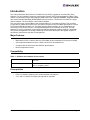
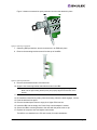
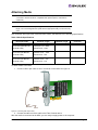
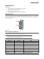
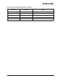
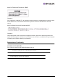
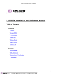
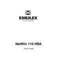
LPe12000 and LPe12002
HBA
Installation Manual
Last updated January 29, 2008
Copyright© 2008 Emulex Corporation. All rights reserved worldwide. No part of this document may be reproduced
by any means nor translated to any electronic medium without the written consent of Emulex Corporation.
Information furnished by Emulex Corporation is believed to be accurate and reliable. However, no responsibility is
assumed by Emulex Corporation for its use; or for any infringements of patents or other rights of third parties which
may result from its use. No license is granted by implication or otherwise under any patent or patent rights of Emulex
Corporation.
Emulex, AutoPilot Installer, BlockGuard, cLAN, FabricStream, FibreSpy, Giganet, HBAnyware, InSpeed, IntraLink,
LightPulse, MultiPulse, SAN Insite, SBOD and Vixel are registered trademarks, and AutoPilot Manager, EZPilot,
SLI and VMPilot are trademarks, of Emulex Corporation. All other brand or product names referenced herein are
trademarks or registered trademarks of their respective companies or organizations.
Emulex provides this manual "as is" without any warranty of any kind, either expressed or implied, including but not
limited to the implied warranties of merchantability or fitness for a particular purpose. Emulex Corporation may
make improvements and changes to the product described in this manual at any time and without any notice. Emulex
Corporation assumes no responsibility for its use, nor for any infringements of patents or other rights of third parties
that may result. Periodic changes are made to information contained herein; although these changes will be
incorporated into new editions of this manual, Emulex Corporation disclaims any undertaking to give notice of such
changes.
LPe12000 and LPe12002 Hardware Installation Manual
Page ii
Table of Contents
Introduction................................................................................................................................................... 1
Major Features ................................................................................................................................ 1
Compatibility .................................................................................................................................... 1
Prerequisites.................................................................................................................................... 1
Setting the Jumpers...................................................................................................................................... 2
Installing the Host Bus Adapter .................................................................................................................... 3
Attaching Media............................................................................................................................................ 5
Applying Power............................................................................................................................................. 6
Viewing the LEDs ............................................................................................................................ 6
POST Conditions and Results ......................................................................................................... 6
References ................................................................................................................................................... 8
Specifications .................................................................................................................................. 8
FCC and Regulatory Notices ........................................................................................................... 9
Declaration of Conformity .............................................................................................................. 10
Laser Safety Notice ....................................................................................................................... 12
LPe12000 and LPe12002 Hardware Installation Manual
Page iii
Introduction
This manual describes the Emulex® LPe12000 and LPe12002, 8 gigabit per second (Gb/s) Fibre
Channel (FC) to Peripheral Component Interconnect Express (PCIe) host bus adapters (HBAs). They
feature a revolutionary design with integrated ARM-1156 cores, integrated SERDES, integrated SRAM,
and external Double-Data Rate (DDRII SRAM) memory structure. The Emulex LPe12000 is a singlechannel adapter. The LPe12002 is a dual-channel adapter.
The core technology of these HBAs is the ninth generation FC controller by Emulex. The controller
incorporates a multifunction native PCIe core that is compliant to the PCIe Base Specification 2.0 and
PCI Express CEM Specification 2.0. The HBAs support packet transfers up to 5 gigatransfers per
second (5.0 GT/s) on the PCIe link. The supported physical PCIe connector is x4 or x8. The fully
featured FC port is compliant to various American National Standards Institute (ANSI) FC standards.
The product is targeted at FC storage networking environments that require the highest degrees of
robustness, performance and ease of management.
Major Features
•
Multifunction PCIe 2.0 device with one (LPe12000) or two independent FC ports (LPe12002)
•
Auto-negotiation between 2-Gb/s, 4-Gb/s or 8-Gb/s FC link attachments
•
Complies with the PCIe base and CEM 2.0 specifications:
•
Built-in temperature sensor
Compatibility
Table 1. Software and Hardware Environments
Software Environments
Windows Server 2003, Windows Server 2008, Windows Vista, Sun Solaris
and Linux
Hardware Environments
PCIe 2.0 and CEM 2.0 compliant systems and backwards compatible to 1.0a
and 1.1 compliant systems.
Prerequisites
•
PCIe 2.0 compliant systems: x4 or x8 lane transfer link interface:
•
3.3 V and 12 V power from PCIe slot required for operation
LPe12000 and LPe12002 Hardware Installation Manual
Page 1
Setting the Jumpers
Caution: Emulex LightPulse® HBAs contain electronic components that can be damaged by static
electricity through an electrostatic discharge (ESD) event. To prevent ESD damage, maintain
constant contact with any grounded metal surface. A grounding wrist strap is useful for this
purpose. Handle the card carefully at all times and preferably by the edges. Avoid touching
electronic components and keep the card in the original packaging until you are ready for
installation.
The device ID jumpers are used in custom applications. Do not change the jumper settings for a
standard Emulex installation.
The LPe12000 HBA has one six-post jumper block that controls the HBA's device ID. The LPe12002
HBA has two six-post jumper blocks that control the HBA's device ID for Ports 0 and 1. Select the ID by
installing a jumper between posts 1 and 2, or 3 and 4, or 5 and 6. If no jumper is installed, the default
device ID is 0x1AE5.
Table 1. Jumper Settings (Port 0 on the LPe12000 - Ports 0 and 1 on the LPe12002)
PCI Identifier
P0_JX (Port 0)
P1_JX (Port 1)
F100
1–2
1–2
F101
3–4
3–4
1AE5*
5–6
5–6
Note: * Without a jumper, the HBA reports a device ID of 0x1AE5. Most software drivers
require a PCI device ID of F100 to properly identify and control the HBA. Do not
attempt to operate the HBA with the PCI device ID set to 0x1AE5 unless
recommended by the driver installation instructions.
Figure 1: The LPe12000 and LPe12002 Jumper Settings
LPe12000 and LPe12002 Hardware Installation Manual
Page 2
Installing the Host Bus Adapter
The Emulex LPe12000 and LPe12002 host bus adapters (HBAs) use a removable optical transceiver. If
you need to change the bracket for HBA installation, you must first remove this transceiver from its
housing (cage). This document explains how to install the HBA and, if necessary, how to remove the
transceiver and bracket safely. To install the HBA:
1. Each HBA is shipped with several numbers clearly marked on the board. these include
•
IEEE Address
•
World Wide Name (WWN)
•
Serial number
The IEEE address is a unique 64-bit identifier that you use when configuring your system. The
FC industry uses the World Wide Name (WWN) derived from the IEEE address for FC connectivity. If the adapter has two ports, there are two IEEE addresses and two WWNs. Use the serial
number when communicating with Emulex. Record these numbers before installation.
2. Turn off the computer and unplug it.
3. Remove the computer case.
4. Follow steps 5–12 to change the bracket if they are different sizes. Otherwise, skip to step 13.
Note: The HBA comes with a standard PCIe bracket installed. A low-profile bracket is
included in the box with the HBA. The low-profile mounting bracket is shorter than the
standard bracket; approximately 3.11 in. (7.9 cm) compared to 4.75 in. (12.06 cm)
long.
5. To change the bracket, you must first remove the transceiver from its cage assembly.
CAUTION: This is a delicate operation–take care not to damage the transceiver.
The HBA uses different types of transceivers. Figure 2 shows an example of one type showing
the bail (handle) extended.
bail (handle)
Figure 2: Example of a transceiver
6. To remove the transceiver, pull the bail (handle) out and down to release the latch and gently pull
the transceiver out. Do not force it. After the latch is released, the transceiver slides out easily.
LPe12000 and LPe12002 Hardware Installation Manual
Page 3
Figure 3 shows one transceiver partly extracted and the other latched in place
Figure 3: Removing a transceiver
7. Observing ESD precautions, store the transceiver in an ESD-safe place.
8. Remove the mounting bracket screws from the top of the HBA.
Figure 4: Removing the Bracket
9. Remove the bracket and store it for future use.
10. Align the new mounting bracket tabs with the holes in the HBA.
Note: Be careful not to push the bracket past the transceiver housing's grounding tabs.
Make sure the light emitting diodes (LEDs) are properly aligned with the holes in the
bracket.
11. Re-install the screws that attach the HBA to the bracket.
12. Re-install the transceiver by sliding it into the housing. When the latch engages, it clicks.
13. Push the bail back into place.
14. Remove the blank panel from an empty x8 or higher PCIe bus slot.
15. Insert the HBA into the empty slot. Press firmly until the adapter is seated.
16. Secure the HBA's mounting bracket to the case with the panel screw or clip.
17. Replace the computer case and tighten case screws.
The HBA is now installed in the PC and is ready for media attachment.
LPe12000 and LPe12002 Hardware Installation Manual
Page 4
Attaching Media
Note: The HBA will not allow normal data transmission on an optical link unless it is
connected to another similar or compatible laser product (that is, multimode to
multimode.)
Note: The HBA will not automatically downgrade to the required FC speed based on cable
length. You must downgrade the speed with the appropriate utility or link errors may
occur.
Use multimode fiber optic cable, with short-wave lasers, that adheres to the following specifications:
Table 5. Media Specifications
Fiber Optic Cable
Maximum Length
Minimum Length
Connector
OM3 - Multimode 50/125
micron fiber (2000 MHz*km
bandwidth cable)
2.125Gbps: 0.5m - 500m
4.25Gbps: 0.5m - 380m
8.5Gb/s 0.5m – 150m
.5 meters
LC
OM2 - Multimode 50/125
micron fiber (500 MHz*km
bandwidth cable)
2.125Gb/s: 0.5m – 300m
4.25Gb/s: 0.5m – 150m
8.5Gb/s 0.5m – 50m
.5 meters
LC
OM1 - Multimode 62.5/125
micron fiber (200 MHz*km
bandwidth cable)
2.125Gb/s: 0.5m – 150m
4.25Gb/s: 0.5m – 70m
8.5Gb/s 0.5m – 21m
.5 meters
LC
To attach media to the HBA:
1. Connect a fiber optic cable to an LC connector on the HBA. See figure 6.
Figure 6: Connecting Fiber Optic Cable
2. Connect the other end of the cable to the Fibre Channel device.
After the media is connected to the HBA, you are ready to apply power to the computer.
LPe12000 and LPe12002 Hardware Installation Manual
Page 5
Applying Power
To apply power:
1. Verify that the HBA is securely installed in the computer.
2. Verify that the correct media is attached.
3. Plug in the computer and turn it on.
4. Watch the LEDs for Power On Self Test (POST) results.
Viewing the LEDs
You can see green and yellow LEDs through openings in the HBA's mounting bracket. The green LED
means firmware operation and the yellow LED means port activity. Each port has a corresponding set of
green and yellow LEDs.
Port 0
LEDs
Port 1
LEDs
Figure 7: LEDs
POST Conditions and Results
The following table summarizes POST conditions and results:
Note: For the Link Rate conditions, there is a 1 second pause when the LED is off between
each group of fast blinks (2, 3 or 4). Observe the LED sequence for several seconds
to be sure you have correctly identified the pattern.
Table 8. POST Conditions and Results
Yellow LED
Green LED
State
Off
Off
Wake-up failure (Dead board)
On
Off
POST failure (Dead board)
Slow Blink
Off
Wake-up failure monitor
Fast Blink
Off
POST failure
Flashing
Off
POST processing in progress
Off
On
Failure while functioning
On
On
Failure while functioning
2 Fast Blinks
On
2Gb Link rate-Normal, link up
3 Fast Blinks
On
4Gb Link rate-Normal, link up
LPe12000 and LPe12002 Hardware Installation Manual
Page 6
Table 8. POST Conditions and Results (Continued)
Yellow LED
Green LED
State
4 Fast Blinks
On
8Gb Link rate-Normal, link up
Off
Slow Blink
Normal-link down or not started
Slow Blink
Slow Blink
Off-line for download
Fast Blink
Slow Blink
Restricted off-line mode (Waiting for restart)
Flashing
Slow Blink
Restricted off-line mode (Test active)
LPe12000 and LPe12002 Hardware Installation Manual
Page 7
References
Specifications
Table 9. LPe12000 and LPe12002 Specifications
Parameter
Range
Media Interface
The controller interfaces to the physical media through an FC-0 Media Interface
(FC-PI compliant transceiver), and then connects through dual optical fiber LC
connectors.
Physical Dimensions
Low-profile MD2 form factor, 6.600 inches by 2.713 inches, and accommodates
both the full-height and low-profile bracket.
Power Requirements
LPe12000
• 1.1 watts (typical) @ +3.3 V ±9%
• 2.0 watts (maximum) @ +3.3 V ±9%
• 5.8 watts (typical) @ +12 V ±8%
• 8.8 watts (maximum) @ +12 V ±8%
• 6.9 watts (typical) total
• 10.1 watts (maximum) total
LPe12002
• 1.7 watts (typical) @ +3.3 V ±9%
• 2.0 watts (maximum) @ +3.3 V ±9%
• 7.1 watts (typical) @ +12 V ±8%
• 11.3 watts (maximum) @ +12 V ±8%
• 8.8 watts (typical) total
• 13.3 watts (maximum) total
Airflow
150 lf/min (minimum)
Temperature
32°F-131°F (0°C-55°C), Operating
-40°F-158°F (-40°C-70°C), Storage
Humidity
5% to 95% non-condensing
Agency Approvals for
LPe12000 and LPe12002
Class 1 Laser Product per DHHS 21CFR (J) & EN60825-1
UL recognized to UL60950-1
CUR recognized to CSA 22.2, No. 60950-1-03
TUV certified by to EN60950-1
FCC Rules, Part 15, Class A
Industry Canada, ICES-003, Class A
EMC Directives 2004/108/EEC (CE Mark)
EN55022, Class A
EN55024
Australian EMC Framework (C-Tick Mark)
AS/NZS CISPR22:2002 Class A
Japan VCCI, Class A
Taiwan BSMI, Class A
Korea MIC, Class A
RoHS Compliant (Directive 2002/95/EC)
China RoHS
LPe12000 and LPe12002 Hardware Installation Manual
Page 8
FCC and Regulatory Notices
LPe12000 and LPe12002 HBA Models
This device complies with Part 15 of the FCC Rules. Operation is subject to the following two conditions:
(1) This device may not cause harmful interference, and (2) this device must accept any interference
received, including interference that may cause undesired operation.
Responsible Party:
Jim McCluney, Chief Executive Officer
Emulex Corporation (714) 662-5600
3333 Susan St. Costa Mesa, CA. 92626 USA
Note: This equipment has been tested and found to comply with the limits for a Class A digital device,
pursuant to part 15 of the FCC Rules. These limits are designed to provide reasonable protection
against harmful interference when the equipment is operated in a commercial environment. This
equipment generates, uses, and can radiate radio frequency energy and, if not installed and used in
accordance with the instruction manual, may cause harmful interference to radio communications.
Operation of this equipment in a residential area is likely to cause harmful interference in which case the
user will be required to correct the interference at his own expense. The reader is cautioned that
changes or modifications made to the equipment not expressly approved by Emulex could void the
user's authority to operate this equipment. The above statement applies to products marketed in the
USA.
This class A digital apparatus meets all requirements of the Industry Canada (IC) Interference - Causing
Equipment Standard (ICES-003).
Cet appareil numerique de la Classe A respecte toutes les exigences du reglement sur le materiel
brouilleur du Canada. This statement applies to products marketed in Canada.
Notice for Japan and Translations (VCCI)
Product Label
This is a Class A product. In a domestic environment this product may cause radio interference in which
case the user may be required to take adequate measures. VCCI—A
Manual Notice
Translation:
This is a Class A product based on the standard of the Voluntary Control Council for Interference by
Information Technology Equipment (VCCI). If this equipment is used in a domestic environment, radio
disturbance may arise. When such trouble occurs, the user may be required to take corrective actions.
LPe12000 and LPe12002 Hardware Installation Manual
Page 9
Notice for Taiwan and Translations (BSMI)
Translation:
This equipment is a Class A ITE, and operation of this equipment in a residential area is likely to cause
harmful interference, in which case users will be required to correct the interference at their own
expense.
Notice for South Korea and Translations (MIC)
Translation:
Class A Equipment: Please note that this equipment has been approved for business purposes with
regards to electromagnetic interference. If purchased in error for use in a residential area, you may wish
to exchange the equipment where you purchased it.
Declaration of Conformity
LPe12000 and LPe12002 HBA
This equipment complies with CISPR22/EN55022 Class A.
WARNING: This is a class A product. In a domestic environment, this product may cause radio
interference requiring the user to take adequate measures.
Note: Changes or modifications not expressly approved by Emulex Corporation could void
the user's authority to operate this equipment.
LPe12000 and LPe12002 Hardware Installation Manual
Page 10
LPe12000 and LPe12002 Hardware Installation Manual
Page 11
Laser Safety Notice
This laser safety information contains certification and product information covering laser products
known as optical small form factor transceivers incorporated in Emulex LightPulse host adapters. The
small form factor transceiver is the primary cable connection mechanism for any optical port on the host
adapter. This data is not intended to be a replacement for any safety regulations and standards; relevant
safety documents should always be consulted if necessary. Contact Emulex Corporation with any
questions or concerns about laser safety.
Certification and Classification
The LPe12000 and LPe12002 host adapters may contain one or more examples of a laser product
known as a small form factor transceiver. This transceiver provides the physical connection to the optical
cable, and its LC-style connector extends through the mounting bracket. In turn, the host adapter can be
inserted into any host system's appropriate PCIe expansion slot.
In the United States, all optical small form factor transceivers sold by Emulex are certified as Class 1
laser products that conform to the requirements contained in the Department of Health and Human
Services (DHHS) regulation 21 CFR subchapter J. The certification is indicated by a label located on the
optical small form factor transceiver.
In Europe, all optical small form factor transceivers sold by Emulex are certified as Class 1 laser
component assemblies that conform to the requirements contained in the CENELEC (European
Committee for Electrotechnical Standardization) standard EN60825-1:1994 (including amendment 11)
and EN60825-2:1994. Small form factor transceivers are certified by a recognized European testing
agency and have appropriate markings on the assembly. The DHHS conformity label and European
conformity mark will not be visible externally once the optical small form factor transceiver is connected
to or inserted in the host adapter and the adapter is installed into a system.
Labeling Requirements
No caution or danger labels are required for use of the small form factor transceiver since they are Class
1 laser component assembly. In the U.S., the only laser safety label required is the DHHS certification
label that already appears on the small form factor transceiver. In Europe, the EN60825-1/EN60825-2
standards require that the system-level product has a Class 1 information label permanently attached
and clearly visible whenever access to the GLM, GBIC, 1x9 and small form factor transceiver optical port
is possible. Each Class 1 product shall have affixed an explanatory label bearing the words:
LPe12000 and LPe12002 Hardware Installation Manual
Page 12
Alternatively, at the discretion of the manufacturer, the same statement may be included in user
information. If a label is used, an example of the IEC Class 1 information label that is suitable for most
European countries is shown below. The label consists of black printing on a white background.
Languages represented on this label are English, German, Finnish and French, and they represent the
minimum set for acceptance of a Class 1 product in most European countries.
Product Information
Small Form Factor Transceiver
The small form factor transceiver is an integrated duplex data link for bi-directional communications over
multimode or single mode optical fiber. Each small form factor transceiver consists of a transmitter and
receiver optical subassembly. The transmitter subassembly contains a semiconductor laser emitting in
the wavelength range of 770 to 860 nanometers for shortwave length small form factor transceivers and
1270 to 1355 nanometers for long wavelength small form factor transceivers. For non-OFC links, the
optical power from the laser transmitter is controlled and maintained at a lower power level. The power
emitted from either an open fiber or open laser transmitter is guaranteed to be below the Class 1 limit.
Class 1 laser products are not considered hazardous. No user maintenance, service operations or
adjustments can be performed the small form factor transceiver.
Usage Restrictions
Failure to comply with these usage restrictions may result in incorrect operation of the system and could
possible lead to points of access that may emit laser radiation levels above the Class 1 limits established
in the U. S. by the DHHS and within Europe by EN60825-1/EN60825-2.
Short wavelength and long wavelength small form factor transceivers allow normal data transmission on
the optical link when they are connected to another compatible laser product. Short wavelength and long
wavelength small form factor transceivers embedded in Emulex host adapter are non-OFC. For nonOFC links, a compatible laser device must be non-OFC and certified as a Class 1 laser product.
Any system level product that incorporates the small form factor transceivers must provide power supply
protection that guarantees a voltage of 5.0 volts or less at the small form factor transceivers. The
functional power supply range of the small form factor transceivers product is specified as 3.135 to
3.465V typically. Operation outside of this range may degrade the performance and lifetime of the
transceiver. The transceiver will remain operational with laser emissions below Class 1 limits provided
the power supply level at the adapter remains at or below 5.0 volts. If the power supply level rises above
5.0 volts, the small form factor transceiver cannot be guaranteed to operate correctly and could result in
laser emissions that may exceed Class 1 limits.
System Level Certification
All host adapters containing embedded small form factor transceivers are certified as Class 1 laser
products within the U.S. and Class 1 laser component assemblies outside of the U.S. Manufacturers of
products properly incorporating the small form factor transceiver do not need to recertify their product for
laser safety. The procedure for full system certification is therefore identical to that used for any other
electronic system. When applying for system level certification to electronic standards such as IEC950,
the regulatory engineers may want to see the DHHS and European conformity labeling on the small form
LPe12000 and LPe12002 Hardware Installation Manual
Page 13
factor transceiver, and the system level documentation and labeling. Copies of the certificate of
conformity for any small form factor transceiver sold by Emulex can be obtained upon request from
Emulex Corporation, Costa Mesa.
LPe12000 and LPe12002 Hardware Installation Manual
Page 14