1
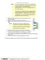
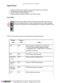
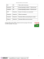
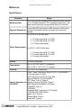
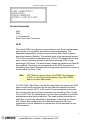
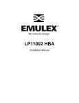
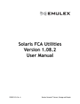
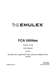
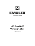
Emulex Documentation, Drivers and Software
LP1050DC Installation and Reference Manual
Table of Contents
Installation
Features
Compatibility
Prerequisites
Install HBA
Attach Media
Apply Power
View LEDs
Reference
Specifications
FCC Statement
Declaration of Conformity
Laser Safety
1
Emulex Documentation, Drivers and Software
Installation
Features
The LP1050DC host bus adapter offers a highly integrated 2Gb/s Fibre Channel HBA
for use in servers based on either the conventional PCI or PCI-X 1.0a expansion bus
architectures. The LP1050DC delivers exceptional performance through the use of a
sixth generation Emulex Thor controller. The Thor high-performance controller is a
highly integrated dual-channel device that combines industry standard embedded
ARM9 processors, 1Gig/2Gig SERDES and protocol technology into a single module.
The LP1050DC is a dual-channel HBA in a low-profile PCI (MD2) compliant card
format.
Major Features
●
●
●
●
●
●
●
●
●
●
●
●
●
●
●
Full duplex 2Gb/s Fibre Channel delivering up to 400MB/s (per channel)
Superior transaction processing performance
Automatic speed negotiation
Automatic topology detection
Full fabric support using F_Port and FL_port connections
Onboard hardware context cache for superior fabric performance
Support for use of multiple concurrent protocols (SCSI and IP)
Full support for both FC service class 2 and 3
Full fabric support in x86 and Itanium environments
Support for FC-Tape (FCP-2) devices
66/100/133 MHz PCI-X 1.0a and PCI 2.3 compatibility
End-to-end parity protection for high data integrity
Robust suite of software supporting Windows Server 2003, Windows 2000,
Windows NT, Linux and NetWare
3.3V signaling, 5V tolerant
Optical small form factor (LC) interface
Compatibility
Software Environments Windows Server 2003, Windows 2000, Windows NT,
Novell Netware and Linux
Hardware Environments PCI hardware platforms: Itanium Processor Family
(for IA-64) and x86 (for IA-32) platforms
2
Emulex Documentation, Drivers and Software
Prerequisites
●
●
●
●
PCI/PCI-X 32- and 64-bit data and addressing
PCI bus computer with a clock rate up to 66 MHz
PCI-X bus computer with a clock rate up to 133 MHz
Media and connectors
copyright © - Emulex Corporation - all rights reserved - 2003
3
Emulex Documentation, Drivers and Software
Install the Host Bus Adapter Board
Caution Emulex LightPulse® Host Bus Adapters (HBAs) contain
electronic components that can be damaged by static
electricity through an electrostatic discharge (ESD) event.
To prevent ESD damage, maintain constant contact with
any grounded metal surface. A grounding wrist strap is
useful for this purpose. Handle the card carefully at all
times and preferably by the edges. Avoid touching
electronic components and keep the card in the original
packaging until you are ready for installation.
1. Record IEEE and serial numbers.
Each host bus adapter (HBA) is shipped with a unique 64-bit identifier called
the IEEE address. The Fibre Channel industry uses a World Wide Name
(WWN) derived from the IEEE address, and this number is needed for Fibre
Channel connectivity. Since this adapter has two ports, there are two IEEE
addresses. The IEEE address is used when configuring your system. The serial
number is used when communicating with Emulex. All numbers are clearly
marked on the board. We recommend that you record these numbers before
installation.
2. Turn off and unplug the computer.
3. Remove the computer case.
Note
For best I/O performance, place the adapter into
an empty PCI-X slot that is running at 133 MHz.
Ensure that the PCI bus is not shared with another
PCI card that can lower the PCI slot clock rate.
4. Remove the blank panel from an empty 32- or 64-bit PCI or PCI-X bus slot.
Compare the removed panel to the bracket on the host bus adapter. Follow
steps 5-8 to change the bracket if they are different sizes. Otherwise, skip to
step 9.
4
Emulex Documentation, Drivers and Software
Note
The host bus adapter comes with a standard PCI
bracket installed. The low-profile mounting bracket
is shorter than the standard bracket;
approximately 3.11 in. (7.9 cm) compared to 4.75
in. (12.06 cm) long.
If you need a low-profile bracket, contact Emulex
Product Information by phone at 800-EMULEX-3
(800-368-5393) or 714-885-3450, or by e-mail at
[email protected]. A low-profile bracket will be
shipped within one business day.
5. Remove the mounting bracket screws from the top of the
host bus adapter.
6. Remove the bracket and store it for future use.
7. Align the new mounting bracket tabs with the holes in the
HBA.
Note
Be careful not to push the bracket past
the transceiver housing's grounding tabs.
Make sure the LEDs are properly aligned
with the holes in the bracket.
8. Replace the screws that attach the HBA to the bracket.
9. Insert the host bus adapter into the empty 32- or 64-bit PCI
or PCI-X bus slot. Press firmly until the adapter is seated.
10. Secure the host bus adapter's mounting bracket to the case with the panel
screw or clip.
11. Replace the computer case and tighten case screws.
The host bus adapter is now installed in the PC and is ready for media attachment.
5
Emulex Documentation, Drivers and Software
Attach Media
Note
The host bus adapter (HBA) will not allow normal data
transmission on an optical link unless it is connected to
another similar or compatible laser product (that is,
multimode to multimode.)
Use multimode fiber optic cable, with short-wave lasers, that adheres to the following
specifications:
Fiber Optic Cable
Maximum Length
Minimum Connector
Length
62.5/125 µm (multimode)
300 meters at 1.0625 Gb/s
150 meters at 2.125 Gb/s
2 meters
LC
50/125 µm (multimode)
500 meters at 1.0625 Gb/s
300 meters at 2.125 Gb/s
2 meters
LC
1. Connect the fiber optic cable to the LC
connector on the HBA.
2. Connect the other end of the cable to
the Fibre Channel device.
After the media is connected to the host bus
adapter, you are ready to apply power to the
computer.
6
Emulex Documentation, Drivers and Software
Apply Power
1.
2.
3.
4.
Verify that the host bus adapter is securely installed in the computer.
Verify that the correct media is attached.
Plug in and turn on the computer.
Observe LEDs for Power On Self Test (POST) results.
View LEDs
Green and yellow LEDs can be seen through openings in the host bus
adapter's mounting bracket. Green indicates power and yellow signifies
port activity. Each port has a corresponding set of green and yellow LEDs.
POST conditions and results are summarized in the following table.
Yellow
LED
Green
LED
State
OFF
OFF
Wake-up failure (dead board). Check the
3.3V LED near the top edge of the HBA
(component side).* If this LED is lit, the slot is
providing 3.3V power.
ON
OFF
POST failure (dead board)
Slow blink
(1 Hz)
OFF
Wake-up failure (dead board)
Fast blink
(4 Hz)
OFF
Failure in POST (dead board)
Flashing
(irregular)
OFF
POST processing in progress
OFF
ON
Failure while functioning
7
Emulex Documentation, Drivers and Software
ON
ON
Failure while functioning
Slow blink
ON
Normal operating condition - 1 GHz link rate
Fast blink
ON
Normal operating condition - 2 GHz link rate
OFF
Slow blink
Normal - link down or not yet started
Slow blink
Slow blink
Offline for download
Fast blink
Slow blink
Restricted offline mode (waiting for restart)
Flashing
Slow blink
Restricted offline mode, test active
*A light-emitting diode (LED) is located near the top edge of the board.
This LED indicates 3.3V power.
8
Emulex Documentation, Drivers and Software
Reference
Specifications
Parameter
Media Interface
Range
The Thor controller interfaces to the physical media through
an FC-0 Media Interface (FC-PI compliant transceiver), and
then connects through a single optical fiber LC connector.
Low-profile MD2 form factor, 6.600 inches by 2.536 inches,
Physical Dimensions and accommodates both the full-height and low-profile
bracket.
In a PCI/PCI-X, 66-MHz host:
●
●
●
Power Requirements
2.0 watts (typical) @ +3.3 VDC
6.1 watts (typical) @ +5.0 VDC
8.1 watts (total typical)
In a PCI-X, 100/133-MHz host:
●
●
●
2.4 watts (typical) @ +3.3 VDC
6.8 watts (typical) @ +5.0 VDC
9.2 watts (total typical)
Airflow
100 lf/min (minimum)
Temperature
32° to 113° F (0° to 45° C), Operating
-40° to 158° F (-40° to 70° C), Storage
Humidity
5% to 95% non-condensing
Class 1 Laser Product per DHHS 21CFR (J) & EN60825-1
UL recognized to UL1950
CUR recognized to CSA 22.2, No. 950
Baurt-certified by TUV to EN60950
FCC Rules, Part 15, Class A
Agency Approvals for Industry Canada, ICES-003, Class A
LP1050DC
EMC Directive 89/336/EEC (CE Mark)
EN55022, Class A
EN55024
Australian EMC Framework (C-Tick Mark)
AS/NZS 3548:1995 Class A
Japan VCCI, Class A
Taiwan BSMI, Class A
Korea MIC, Class A
9
Emulex Documentation, Drivers and Software
FCC and Regulatory Notices
CLASS 1 LASER PRODUCT
LASER KLASSE 1
LUOKAN 1 LASERLAITE
APPAREIL A` LASER DE CLASSE 1
LP10000DC-M2, LP10000-M2, LP1050DC-F2 and LP1050-F2 Models
This device complies with Part 15 of the FCC Rules. Operation is subject to the following two
conditions: (1) This device may not cause harmful interference, and (2) this device must accept
any interference received, including interference that may cause undesired operation.
Responsible Party: Paul Folino, Chief Executive Officer
Emulex Corporation (714) 662-5600
3535 Harbor Blvd. Costa Mesa, CA Corporation 92626 USA
Note:
This equipment has been tested and found to comply with the limits for a Class A digital device,
pursuant to part 15 of the FCC Rules. These limits are designed to provide reasonable
protection against harmful interference when the equipment is operated in a commercial
environment. This equipment generates, uses, and can radiate radio frequency energy and, if
not installed and used in accordance with the instruction manual, may cause harmful
interference to radio communications. Operation of this equipment in a residential area is likely
to cause harmful interference in which case the user will be required to correct the interference
at his own expense. Shielded cables must be used between this equipment and attached
peripheral devices. The reader is cautioned that changes or modifications made to the
equipment not expressly approved by Emulex could void the user's authority to operate this
equipment. The above statement applies to products marketed in the USA
This class A digital apparatus meets all requirements of the Industry Canada (IC) Interference Causing Equipment Standard (ICES-003).
Cet appareil numerique de la Classe A respecte toutes les exigences du reglement sur le
materiel brouilleur du Canada. This statement applies to products marketed in Canada.
10
Emulex Documentation, Drivers and Software
Notice for Japan and Translations (VCCI)
Product Label
This is a Class A product. In a domestic environment this product may cause radio
interference in which case the user may be required to take adequate measures. VCCI—A
Manual Notice
Translation:
This is a Class A product based on the standard of the Voluntary Control Council for
Interference by Information Technology Equipment (VCCI). If this equipment is used in a
domestic environment, radio disturbance may arise. When such trouble occurs, the user may
be required to take corrective actions.
Notice for Taiwan and Translations (BSMI)
Translation:
This equipment is a Class A ITE, and operation of this equipment in a residential
area is likely to cause harmful interference, in which case users will be required to
correct the interference at their own expense.
11
Emulex Documentation, Drivers and Software
Notice for South Korea and Translations (MIC)
Translation:
Class A Equipment: Please note that this equipment has been approved for
business purposes with regards to electromagnetic interference. If purchased in
error for use in a residential area, you may wish to exchange the equipment where
you purchased it.
12
Emulex Documentation, Drivers and Software
Declaration of Conformity
LP10000DC-M2, LP10000-M2, LP1050DC-F2 and LP1050-F2 Models
This equipment complies with CISPR22/EN55022 Class A.
Warning
This is a class A product. In a domestic environment,
this product may cause radio interference requiring the
user to take adequate measures.
Note
Changes or modifications not expressly approved by
Emulex Corporation could void the user's authority to
operate this equipment.
13
Emulex Documentation, Drivers and Software
14
Emulex Documentation, Drivers and Software
Laser Safety Notice
This laser safety information contains certification and product information covering
laser products known as optical Gigabaud Link Modules (GLMs), Gigabit Interface
Converters (GBICs), 1x9 and small form factor transceivers sold as accessories to or
incorporated in Emulex LightPulse host adapters. The GLM, GBIC, 1x9 and small form
factor transceiver are the primary cable connection mechanisms for any optical port on
the host adapter and hub. This data is not intended to be a replacement for any safety
regulations and standards; relevant safety documents should always be consulted if
necessary. Contact Emulex Corporation with any questions or concerns about laser
safety.
Certification and Classification
Labeling Requirements
Product Information
Usage Restrictions
System Level Certification
Certification and Classification
LP6000 and LP7000E PCI host adapters may contain a laser product known as an
optical Gigabaud Link Module (GLM). The optical GLM is attached to the host
adapter using an 80-pin connector and extends through the mounting bracket. In
turn, the host adapter can be inserted into any host system's PCI slot.
The LH5000 hub may contain a laser product known as a Gigabit Interface
Connector (GBIC). The GBIC provides the physical connector to the optical cable.
The GBIC can be inserted into any pluggable hub port.
The LP8000, LP850 and LP9000 PCI host adapter may contain a laser product
known as a Gigabit Interface Converter (GBIC) or an embedded 1x9 transceiver.
The GBIC and or 1x9 transceiver provide the physical connection to the optical
cable, and its SC-style connector extends through the mounting bracket. In turn, the
host adapter can be inserted into any host system’s PCI slot.
The LP9002, LP9002L, LP952L, LP9002S, LP9002DC, LP9002C, LP9402DC,
LP9802, LP982, LP9802DC, LP10000, LP10000DC, LP1050DC and LP1050 host
adapters may contain a laser product known as a small form factor transceiver. This
transceiver provides the physical connection to the optical cable, and its LC-style
connector extends through the mounting bracket. In turn, the host adapter can be
inserted into any host system's appropriate PCI/PCI-X/cPCI/SBus expansion slot.
15
Emulex Documentation, Drivers and Software
In the United States, all optical GLMs, GBICs, 1x9 and small form factor
transceivers sold by Emulex are certified as Class 1 laser products that conform to
the requirements contained in the Department of Health and Human Services
(DHHS) regulation 21 CFR subchapter J. The certification is indicated by a label
located on the optical GLM, GBIC, 1x9 or small form factor transceiver.
In Europe, all optical GLMs, GBICs, 1x9 and small form factor transceivers sold by
Emulex are certified as Class 1 laser component assemblies that conform to the
requirements contained in the CENELEC (European Committee for Electrotechnical
Standardization) standard EN60825-1:1994 (including amendment 11) and
EN60825-2:1994. GLMs, GBICs, 1x9 and small form factor transceivers are certified
by a recognized European testing agency and have appropriate markings on the
assembly. The DHHS conformity label and European conformity mark will not be
visible externally once the optical GLM, GBIC, 1x9 or small form factor transceiver is
connected to or inserted in the host adapter and the adapter is installed into a
system.
Labeling Requirements
No caution or danger labels are required for use of the GLM, GBIC, 1x9 or small
form factor transceiver since they are Class 1 laser component assembly. In the U.
S., the only laser safety label required is the DHHS certification label that already
appears on the GLM, GBIC, 1x9 and small form factor transceiver. In Europe, the
EN60825-1/EN60825-2 standards require that the system-level product has a Class
1 information label permanently attached and clearly visible whenever access to the
GLM, GBIC, 1x9 and small form factor transceiver optical port is possible. Each
Class 1 product shall have affixed an explanatory label bearing the words:
Alternatively, at the discretion of the manufacturer, the same statement may be
included in user information. If a label is used, an example of the IEC Class 1
information label that is suitable for most European countries is shown below. The
label consists of black printing on a white background. Languages represented on
this label are English, German, Finnish and French, and they represent the
minimum set for acceptance of a Class 1 product in most European countries.
16
Emulex Documentation, Drivers and Software
Product Information
GLM
GBIC
1 x 9 Transceiver
Small Form Factor Transceiver
GLM
The optical GLM is a single port communications card. Each communication
port consists of a transmitter and receiver optical subassembly. The
transmitter subassembly contains a semiconductor laser diode of gallium
aluminum arsenide (GaAlAs). This material emits in the wavelength range of
770 to 860 nanometers for shortwave and 1270 to 1355 nanometers for long
wave, and are commonly referred to as short wavelength (SW) or long
wavelength (LW) lasers. The discrete laser diodes are classified as Class 3B
laser products. Once they are incorporated into the GLM, the product’s
automatic power control maintains the average power launched into a fiber at
a value below the Class 1 limit.
Note
OFC GLMs are found only on the LP6000. Any reference
to OFC or non-OFC products applies only to the LP6000,
and not to other HBA models.
For OFC GLMs (Open Fiber Control) the optical fiber link between two GLM
ports is continuously monitored by the open fiber link detection and laser
safety control system (OFC). In the event of a break anywhere in the path,
this control system prevents laser emissions from exceeding Class 1 levels.
For non-OFC links, the optical power from the laser transmitter is controlled
and maintained at a lower power level. The power emitted from either an
open fiber or open laser transmitter is guaranteed to be below the Class 1
limit. Class 1 laser products are not considered hazardous. No user
maintenance, service operations or adjustments can be performed on any
GLM accessory.
17
Emulex Documentation, Drivers and Software
GBIC
The optical GBIC is an integrated duplex data link for bi-directional
communications over multimode or single mode optical fiber. Each GBIC
consists of a transmitter and receiver optical subassembly. The transmitter
subassembly contains a semiconductor laser emitting in the wavelength
range of 770 to 860 nanometers for shortwave length GBICs and 1270 to
1355 nanometers for long wavelength GBICs. For non-OFC links, the optical
power from the laser transmitter is controlled and maintained at a lower
power level. The power emitted from either an open fiber or open laser
transmitter is guaranteed to be below the Class 1 limit. Class 1 laser
products are not considered hazardous. No user maintenance, service
operations or adjustments can be performed the GBIC.
Small Form Factor Transceiver
The small form factor transceiver is an integrated duplex data link for bidirectional communications over multimode or single mode optical fiber.
Each small form factor transceiver consists of a transmitter and receiver
optical subassembly. The transmitter subassembly contains a semiconductor
laser emitting in the wavelength range of 770 to 860 nanometers for
shortwave length small form factor transceivers and 1270 to 1355
nanometers for long wavelength small form factor transceivers. For non-OFC
links, the optical power from the laser transmitter is controlled and
maintained at a lower power level. The power emitted from either an open
fiber or open laser transmitter is guaranteed to be below the Class 1 limit.
Class 1 laser products are not considered hazardous. No user maintenance,
service operations or adjustments can be performed the small form factor
transceiver.
1x9 Transceiver
The 1x9 transceivers is an integrated duplex data link for bi-directional
communications over multimode fiber. Each 1x9 consists of a transmitter and
receiver optical subassembly. The transmitter subassembly contains a
semiconductor laser emitting in the wavelength range of 770 to 860
nanometers for shortwave 1x9s. For non-OFC links, the optical power from
the laser transmitter is controlled and maintained at a lower power level. The
power emitted from either an open fiber or open laser transmitter is
guaranteed to be below the Class 1 limit. Class 1 laser products are not
considered hazardous. No user maintenance, service operations or
adjustments can be performed the 1x9 transceiver.
18
Emulex Documentation, Drivers and Software
Usage Restrictions
Failure to comply with these usage restrictions may result in incorrect operation of
the system and could possible lead to points of access that may emit laser radiation
levels above the Class 1 limits established in the U. S. by the DHHS and within
Europe by EN60825-1/EN60825-2.
GLM
GBIC
1 x 9 Transceiver
Small Form Factor Transceiver
GLM
The GLM is designed and certified for applications using point-to-point optical fiber
links only. Use of the product with multiple input or multiple output optical links (for
example, star couplers) is prohibited since it is incompatible with the GLM’s
certification.
The GLM will not allow normal data transmission on the optical link unless it is
connected to another similar GLM or compatible laser product. For OFC GLMs,
another manufacturer’s laser product is not considered compatible unless it contains
the open fiber link detection and laser safety control system (OFC) and is properly
certified as a Class 1 laser product. Similarly, for non-OFC GLMs, a compatible
laser device must be non-OFC.
Any system level product that incorporates the GLM must provide power supply
protection that guarantees a voltage of 6.0 volts or less at the GLM. The functional
power supply range of the GLM product is specified as 4.75 to 5.25 volts typically.
Operation outside of this range may degrade the performance and lifetime of the
GLM. The GLM will remain operational with laser emissions below Class 1 limits
provided the power supply level at the adapter remains at or below 6.0 volts. If the
power supply level rises above 6.0 volts, the GLM cannot be guaranteed to operate
correctly and could result in laser emissions that may exceed Class 1 limits.
GBIC
Short wavelength and long wavelength GBICs allow normal data transmission on
the optical link when they are connected to another compatible laser product. Short
wavelength and long wavelength GBICs sold by Emulex as accessories are nonOFC devices. For non-OFC links, a compatible laser device must be non-OFC and
certified as a Class 1 laser product.
19
Emulex Documentation, Drivers and Software
1 x 9 Transceiver
Short wavelength 1x9 transceivers allow normal data transmission on the optical
link when they are connected to another compatible laser product. Short wavelength
1x9s embedded in Emulex host adapters are non-OFC. For non-OFC links, a
compatible laser device must be non-OFC and certified as a Class 1 laser product.
Small Form Factor Transceiver
Short wavelength and long wavelength small form factor transceivers allow normal
data transmission on the optical link when they are connected to another compatible
laser product. Short wavelength and long wavelength small form factor transceivers
embedded in Emulex host adapter are non-OFC. For non-OFC links, a compatible
laser device must be non-OFC and certified as a Class 1 laser product.
Any system level product that incorporates the small form factor transceivers must
provide power supply protection that guarantees a voltage of 5.0 volts or less at the
small form factor transceivers. The functional power supply range of the small form
factor transceivers product is specified as 3.135 to 3.465V typically. Operation outside
of this range may degrade the performance and lifetime of the transceiver. The
transceiver will remain operational with laser emissions below Class 1 limits provided
the power supply level at the adapter remains at or below 5.0 volts. If the power supply
level rises above 5.0 volts, the small form factor transceiver cannot be guaranteed to
operate correctly and could result in laser emissions that may exceed Class 1 limits.
System Level Certification
All GLMs and GBICs sold as accessories by Emulex or host adapters containing
embedded 1x9 or small form factor transceivers are certified as Class 1 laser products
within the U.S. and Class 1 laser component assemblies outside of the U.S.
Manufacturers of products properly incorporating the GLM, GBIC, 1x9 or small form
factor transceiver do not need to recertify their product for laser safety. The procedure
for full system certification is therefore identical to that used for any other electronic
system. When applying for system level certification to electronic standards such as
IEC950, the regulatory engineers may want to see the DHHS and European conformity
labeling on the GLM, GBIC, 1x9 or small form factor transceiver, and the system level
documentation and labeling. Copies of the certificate of conformity for any GLM, GBIC,
1x9 or small form factor transceiver sold by Emulex can be obtained upon request from
Emulex Corporation, Costa Mesa.
20