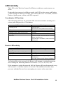
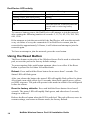
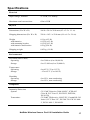
1
Installation Guide NetBotz® Wireless Sensor Pod 180 NBPD0180 Contents Introduction. . . . . . . . . . . . . . . . . . . . . . . . . . . . . . . . . . . . . . . . . . . 1 Product description . . . . . . . . . . . . . . . . . . . . . . . . . . . . . 1 Supported appliances . . . . . . . . . . . . . . . . . . . . . . . . . . . 1 Supported sensors . . . . . . . . . . . . . . . . . . . . . . . . . . . . . . 1 ZigBee® Certified . . . . . . . . . . . . . . . . . . . . . . . . . . . . . . . 2 Document overview . . . . . . . . . . . . . . . . . . . . . . . . . . . . . 2 Additional documentation . . . . . . . . . . . . . . . . . . . . . . . . . 2 Physical Description . . . . . . . . . . . . . . . . . . . . . . . . . . . . . . . . . . . 3 Front view . . . . . . . . . . . . . . . . . . . . . . . . . . . . . . . . . . . . 3 Inventory . . . . . . . . . . . . . . . . . . . . . . . . . . . . . . . . . . . . . . . . . . . . . 4 Components of the Wireless Sensor Network. . . . . . . . . . . . . . . 5 Installing the Wireless Sensor Network . . . . . . . . . . . . . . . . . . . . 6 Mounting the Wireless Sensor Pod . . . . . . . . . . . . . . . . . . . . . . . 7 Toolless peg-mount installation . . . . . . . . . . . . . . . . . . . . 7 External installation . . . . . . . . . . . . . . . . . . . . . . . . . . . . . 8 Connecting a Door Switch or Temperature Sensor . . . . . . . . . . 8 Powering the Coordinator . . . . . . . . . . . . . . . . . . . . . . . . . . . . . . . 9 Configuring the Coordinator . . . . . . . . . . . . . . . . . . . . . . . . . . . . . 9 Disconnecting a Coordinator . . . . . . . . . . . . . . . . . . . . . 10 Internal sensor listing . . . . . . . . . . . . . . . . . . . . . . . . . . . 10 Powering a Router . . . . . . . . . . . . . . . . . . . . . . . . . . . . . . . . . . . . 11 Internal sensor listing . . . . . . . . . . . . . . . . . . . . . . . . . . . 11 Powering an End Device . . . . . . . . . . . . . . . . . . . . . . . . . . . . . . . 12 Internal sensor listing . . . . . . . . . . . . . . . . . . . . . . . . . . . 12 LED Activity . . . . . . . . . . . . . . . . . . . . . . . . . . . . . . . . . . . . . . . . . 13 Coordinator LED activity . . . . . . . . . . . . . . . . . . . . . . . . 13 Router LED activity . . . . . . . . . . . . . . . . . . . . . . . . . . . . 13 End Device LED activity . . . . . . . . . . . . . . . . . . . . . . . . . 14 Using the Reset Button . . . . . . . . . . . . . . . . . . . . . . . . . . . . . . . . 14 NetBotz Wireless Sensor Pod 180 Installation Guide i Configuring and Monitoring Sensors . . . . . . . . . . . . . . . . . . . . . 15 Receiving and sending data . . . . . . . . . . . . . . . . . . . . . . 15 Updating the Wireless Sensor Pod. . . . . . . . . . . . . . . . . . . . . . . 16 Cleaning the Wireless Sensor Pod . . . . . . . . . . . . . . . . . . . . . . . 16 Specifications . . . . . . . . . . . . . . . . . . . . . . . . . . . . . . . . . . . . . . . 17 Two Year Limited Factory Warranty . . . . . . . . . . . . . . . . . . . . . . 18 Obtaining service . . . . . . . . . . . . . . . . . . . . . . . . . . . . . . 21 Introduction Product description The NetBotz® Wireless Sensor Pod 180 (NBPD0180) connects to a NetBotz appliance and allows you to monitor the temperature and humidity in a rack in your data center. Additional sensors allow you to monitor rack door access, and multiple temperature readings for the rack. The Wireless Sensor Pod 180 can be configured as the Coordinator, a Router, or an End Device in your wireless sensor network. The Wireless Sensor Pods in the network are monitored by a single NetBotz appliance. Supported appliances You can connect the Wireless Sensor Pod to any of the following appliances: • NetBotz Rack Monitor 450 (NBRK0451) • NetBotz Room Monitor 455 (NBWL0455, NBWL0456) • NetBotz Rack Monitor 550 (NBRK0551) • NetBotz Rack Monitor 570 (NBRK0570) Supported sensors The Wireless Sensor Pod includes three Universal Sensor ports for connecting APC temperature sensors and APC door contact sensors. The pod also has an internal temperature and humidity sensor. Supported sensors are: Sensor Name NetBotz Door Switch Sensor for APC Racks NetBotz Door Switch Sensor for APC Racks NetBotz Door Switch Sensor for Third Party Racks NetBotz Door Switch Sensor for Rooms or Third Party Racks APC Temperature Sensor NetBotz Temperature Sensor Length APC Part Number 12 ft 62 in 62 in 50 ft NBES0303 NBES0313 NBES0312 NBES0302 13 ft 32 in AP9335T NBES0311 Warning: Only the sensors listed above are compatible with the Wireless Sensor Pod. The APC Temperature and Humidity Sensor (AP9335TH) is not compatible. Other sensors or devices will not function and will damage the device. NetBotz Wireless Sensor Pod 180 Installation Guide 1 ZigBee® Certified The Wireless Sensor Pod is ZigBee Certified. ZigBee is a wireless mesh networking standard for low-power applications. Schneider Electric is a member of the ZigBee Alliance. Full information on the ZigBee standard can be found at the ZigBee Alliance website: http://www.zigbee.org. Document overview The NetBotz Wireless Sensor Pod 180 Installation Guide describes how to install the Wireless Sensor Pod in a rack, configure its mode and settings, attach it to a NetBotz appliance, and configure a wireless sensor network with other Wireless Sensor Pods. Specific instructions on installing door contacts and temperature sensors are in the installation instructions for each component. Additional documentation NetBotz Appliance Online Help – Available in the Advanced View of the NetBotz appliance; includes all details for using, managing, and configuring a NetBotz system with one of the following appliances: NetBotz Room Monitor 455 (NBWL0455, NBWL0456), NetBotz Rack Monitor 450 (NBRK0451), NetBotz Rack Monitor 550 (NBRK0551), or NetBotz Rack Monitor 570 (NBRK0570). 2 NetBotz Wireless Sensor Pod 180 Installation Guide Physical Description Front view Item Description Battery Holds 2 AA batteries when in End Device mode. Compartment Universal Sensor Port for a Temperature Probe or Door Contact sensor. Port #2 Universal Sensor Port #3 Port for a Temperature Probe or Door Contact sensor. Type-B USB Port Used to connect the Wireless Sensor Pod to a NetBotz appliance when used in Coordinator mode, or to supply USB power when in Router mode. Status LED Used to signify the mode and current state of the Wireless Sensor Pod. Reset button Used to reboot the pod or reset the pod to factory defaults. Universal Sensor Port for a Temperature Probe or Door Contact sensor. Port #1 (occluded) NetBotz Wireless Sensor Pod 180 Installation Guide 3 Inventory Inspect the contents of the package to ensure that the parts included match those shown below. Report missing or damaged contents to Schneider Electric or your APC reseller. The shipping and packaging materials are recyclable. Please save them for later use or dispose of them appropriately. Item Description NetBotz Wireless Sensor Pod 180 Plastic Push Rivets w/ sleeves (3) Lithium Batteries (2) #8 x 3/4-in Phillips head screws (2) Plastic Wall Anchor (2) Type A/B USB Cable Wall-mounting bracket AC Adapter (not shown) Literature Kit (not shown) 4 NetBotz Wireless Sensor Pod 180 Installation Guide Components of the Wireless Sensor Network The Wireless Sensor Pod can be configured to act in three different modes on a ZigBee wireless sensor network: Coordinator, Router, and End Device. The mode of a Wireless Sensor Pod is determined by the manner in which power is supplied to the device. The factory default for the Wireless Sensor Pod is Router mode. Host Appliance. A wireless sensor network is monitored by a single NetBotz appliance, listed in “Supported appliances” on page 1. The appliance collects data from the wireless sensor network, and generates alerts based on sensor thresholds. The host appliance supports a total of 26 Wireless Sensor Pods, including the Coordinator, in the wireless sensor network. Coordinator. Each NetBotz host appliance and wireless sensor network must have one and only one Coordinator. The Coordinator is connected directly to the host appliance via a USB-B to USB-A cable. It reports sensor data from its internal sensors and any attached external sensors, and from the other Wireless Sensor Pods on the network, and provides firmware updates to the wireless network, when available. The Coordinator must be configured as a serial device on the host appliance using the Wireless Sensor Setup task in the Advanced View. Router. The factory default for the Wireless Sensor Pod is Router mode. A Wireless Sensor Pod configured as a Router extends the range of the wireless sensor network and passes information back and forth from the Coordinator to the End Devices, and from itself to Coordinator. It also reports sensor data from its internal sensors and any attached external sensors. A wireless sensor network can contain multiple Routers; one Router for every three racks in the row is recommended. A pod powered by an AC-USB adapter, not attached to the NetBotz appliance, is automatically configured as a Router. If a sensor pod has previously been configured as a Coordinator, you must first reset the pod to factory defaults before powering it as a Router. See “Using the Reset Button” on page 14. End Device. An End Device monitors attached and internal sensors and sends data back to the monitoring appliance through the network. Any Wireless Sensor Pod powered by batteries is automatically configured as an End Device. NetBotz Wireless Sensor Pod 180 Installation Guide 5 Installing the Wireless Sensor Network The order in which you install your wireless network is important. Warning: Although every Wireless Sensor Pod has a battery compartment, ONLY End Devices require batteries. DO NOT insert batteries into a sensor pod that will be a Router or a Coordinator. For best results, power and configure your wireless network as follows: Scan the extended addresses of the Wireless Sensor Pods. Use a barcode scanner to scan the Extended Address QR code (not the serial number) on the label inside the battery compartment door of each Wireless Sensor Pod. Save a list of extended addresses to a text file. To add the extended addresses to your wireless network, copy and paste the list in the Wireless Sensor Setup task in the Advanced View. Select the Coordinator and Routers. Choose the Wireless Sensor Pod that will become the Coordinator. Note the extended address of the Coordinator. Choose one or more Wireless Sensor Pods to become Routers. Mount the sensor pods. Mount the Coordinator, Routers, and End Devices using the instructions in “Mounting the Wireless Sensor Pod” on page 7. Power the Coordinator. Power the Coordinator FIRST. Connect one and only one Coordinator to a USB Type A port on the NetBotz appliance. Make a note of the port to which the Coordinator is attached, for example USB-A. Configure the Coordinator. Open the Advanced View, and use the Wireless Sensor Setup task to add the extended addresses of all the Wireless Sensor Pods in your wireless network to the commission list. Apply the commission list to save it to the NetBotz appliance. Ensure the extended address of the Coordinator is in the commission list, and then configure the Coordinator. Power the Routers. Power each Router using the included AC-USB adapter, not directly connected to the NetBotz appliance. To limit traffic on the network, do not power the Routers until after the Coordinator is powered and configured. Power the End Devices. Insert the included batteries into End Devices. To preserve battery life, do not insert the batteries into the End Devices until after the Coordinator and the Routers are powered, and the Coordinator is configured. 6 NetBotz Wireless Sensor Pod 180 Installation Guide Mounting the Wireless Sensor Pod When planning your wireless network installation locations, place each End Device or Router within range of another Router or a Coordinator. The maximum range of the Wireless Sensor Pod is 100 ft (line of sight). This range is a best-case scenario; the signal will be strongly affected by environmental interference. Use the RSSI sensor reading (available in the device’s sensor listing in Advanced View) to tune device placement. A reading above 30% RSSI is ideal. To improve connection strength, it is recommended to use a Router in every third rack to boost reception. Additional information on device placement may be found on the Knowledge Base, http://www.apc.com/support/answers.cfm. Choose the option below that fits your location. Note: Install your wireless network in an environment compatible with the environmental specifications on page 17. Toolless peg-mount installation Note: The toolless peg-mount installation is only available with a NetShelter VX, SX, or SV rack. The Wireless Sensor Pod 180 ships with a pair of plastic rivets and sleeves to be used when mounting the pod in a NetShelter VX, NetShelter SX, or NetShelter SV rack. To mount the Wireless Sensor Pod: 1. Separate the two pieces of the plastic rivets. 2. Place the pod in the desired location on the rack door. Make sure that all external sensors can reach their desired locations from the mounting point. 3. From the outside of the rack, insert the rivet sleeves through the mesh grating and into the mounting holes on the rear of the pod. 4. Insert the push rivet into the sleeve. Push until the rivet is firmly seated. Repeat with the second rivet. 5. Connect the external sensors to the appropriate ports. NetBotz Wireless Sensor Pod 180 Installation Guide 7 External installation The Wireless Sensor Pod ships with a mounting plate to be used when installing a pod in a non-rack location or in a non-Netshelter VX, SX, or SV rack. 1. Separate the two pieces of the plastic push rivets. Note: To avoid equipment damage, use only the hardware provided when installing the brackets. 2. Place the included mounting plate on the back of the pod and align the holes with the mounting holes on the pod. 3. Insert the outer sleeves into the mounting holes on the rear of the plate. 4. Insert the plastic rivets into the anchor sleeves. 5. Use the appropriate hardware to mount the Wireless Sensor Pod in the desired location. Connecting a Door Switch or Temperature Sensor Only connect sensors that are supported by the Wireless Sensor Pod. Each Wireless Sensor Pod can monitor and control up to three door switch sensors or temperature sensors. Connect sensors to the universal sensor ports on the Wireless Sensor Pod. Caution: Only connect approved devices to ports on the Wireless Sensor Pod as directed in this manual. Plugging in other devices may result in equipment damage not covered under warranty. 8 NetBotz Wireless Sensor Pod 180 Installation Guide Powering the Coordinator Power the Coordinator first. Connect one and only one Coordinator to a USB Type A port on the NetBotz appliance. Make a note of the port to which the Coordinator is attached, for example USB-A. Configuring the Coordinator The Coordinator must be configured as a serial device in the Wireless Sensor Setup task in the Advanced View on the host appliance. After connecting the Coordinator: 1. Log in to the host appliance using the Advanced View. 2. Select the Configuration tab and double-click the Wireless Sensor Setup icon. 3. Click Add to enter the extended address of the Wireless Sensor Pod that will be the Coordinator. Note: You can also add the extended addresses of any other Wireless Sensor Pods you are adding to the wireless sensor network. 4. Click Apply to apply the commission list to save it to the NetBotz appliance. 5. Click Configure Coordinator. Find the serial port ID for the Wireless Sensor Pod. It appears as “FTDI FT232BM Compatible (Port A)” or similar. 6. Select “Wireless Sensor Pod 180” in the Device Type Installed dropdown list, and specify the Port Label. 7. In the Navigation pane of Advanced View (the upper left), the Wireless Sensor is listed as “Sensor Pod 180 C” (the “C” denotes that it is the Coordinator). Wait for the pod to complete its configuration; when it is finished, the extended address of the pod will appear as the name of the device. Once the Coordinator is running, the other pods in the wireless sensor network will join the network automatically as long as their extended addresses are in the commission list, and they are powered. To allow multiple wireless sensor networks to exist independently in the same area, the extended addresses in a commission list must not exist in another NetBotz Appliance commission list. NetBotz Wireless Sensor Pod 180 Installation Guide 9 Disconnecting a Coordinator When you disconnect the Coordinator from the host appliance, all of the sensors on the wireless sensor network display as offline. When you reconnect the same Coordinator, it must be manually deleted and reconfigured in the Wireless Sensor Setup task in the Advanced View. The network will then restart, and the sensors will begin reporting data. If you want to connect a different pod to the host appliance to become the Coordinator, you must FIRST remove the extended address of the previous Coordinator from the commission list. See “Configuring the Coordinator” on page 9. Maintaining sensor history. If you right-click a disconnected Coordinator in the Navigation pane in the Advanced View and select “Delete Pod”, all of the Wireless Sensor Pods will be deleted, including any sensor history related to those devices. To maintain your sensor history, remove the Coordinator using the Wireless Sensor Setup dialog. Warning: If a Coordinator is removed from the host appliance after being configured as a serial device, it MUST be manually deleted using the Wireless Sensor Setup dialog. You will not be able to configure a Coordinator if the entry is not deleted, even if the original pod is reconnected. Internal sensor listing When a Coordinator is selected in the Navigation Pane in Advanced View, the following internal sensors are listed in the Sensor Pane (along with any attached external sensors): Sensor Temperature Humidity Dew Point 10 Description The internal temperature sensor reading. The internal humidity sensor reading. The calculated dew point. NetBotz Wireless Sensor Pod 180 Installation Guide Powering a Router A Wireless Sensor Pod must be connected to an AC-USB power source to become a Router. Once its extended address is added to the commission list in the Advanced View, and power is applied, the pod is automatically configured as a Router. Warning: Do not use a NetBotz appliance as the USB power source for a Router device. To configure a Wireless Sensor Pod as a Router: 1. Mount the pod using the instructions in “Mounting the Wireless Sensor Pod” on page 7. 2. Ensure the extended address of the pod is added to the commission list in the Advanced View. 3. Plug the pod into the included AC-USB power source. Internal sensor listing When a Router is selected in the Navigation Pane in Advanced View, the following internal sensors are listed in the Sensor Pane (along with any attached external sensors): Sensor Temperature Humidity Dew Point RSSI Description The internal temperature sensor reading. The internal humidity sensor reading. The calculated dew point. The Received Signal Strength Indicator. This indicates the strength of the signal the Router receives from its parent (either another Router or the Coordinator). A reading above 30% RSSI is ideal. NetBotz Wireless Sensor Pod 180 Installation Guide 11 Powering an End Device A Wireless Sensor Pod must have lithium batteries installed to become an End Device. An End Device reports data from the internal and external sensors to the host appliance, but does not extend the wireless network or pass data to other End Devices. Power End Devices last to preserve battery life. Once its extended address is added to the commission list in the Advanced View, and the lithium batteries are installed, the pod is automatically configured as an End Device. To configure a Wireless Sensor Pod as an End Device: 1. Mount the pod using the instructions in “Mounting the Wireless Sensor Pod” on page 7. 2. Ensure the extended address of the pod is added to the commission list in the Advanced View. 3. Install the provided lithium batteries into the battery compartment. Note: It is highly recommended you use the provided lithium batteries when installing the Wireless Sensor Pod. When necessary, replace the batteries with only the same battery type. Internal sensor listing When an End Device is selected in the Navigation Pane in Advanced View, the following internal sensors are listed in the Sensor Pane (along with any attached external sensors): Sensor Temperature Humidity Dew Point Battery RSSI 12 Description The internal temperature sensor reading. The internal humidity sensor reading. The calculated dew point. The voltage of the batteries. The Received Signal Strength Indicator. Indicates the strength of the signal the Router receives from its parent (either another Router or the Coordinator). A reading above 30% RSSI is ideal. NetBotz Wireless Sensor Pod 180 Installation Guide LED Activity The LED on the Wireless Sensor Pod flashes to indicate certain statuses or alerts. During the boot process in all three modes, the LED on the sensor pod flashes yellow rapidly for about 40 seconds, turns solid yellow for 10 seconds, and then flashes a quick green, yellow, red LED sequence. Coordinator LED activity The following table lists the possible LED activities and their meaning for a sensor pod configured as a Coordinator: LED Activity Flashing green Off Flashing yellow, then solid yellow Solid green Solid red Meaning Normal status The network was formed successfully. Forming a network Booting Joined another network as a Router. Unable to form a network due to wireless energy interference. Relocate the Coordinator, and reboot the sensor pod. Router LED activity LED Activity Solid green Flashing yellow, then solid yellow Solid yellow Off Meaning Normal Status - network present Booting Searching for network The pod was previously configured as a Coordinator. Reset the sensor pod to factory defaults. To limit traffic on the network, the Router will attempt to rejoin the network after waiting the following number of seconds: 5, 15, 30, 60, 120, 300. If the attempts to rejoin the network fail, the Router will scan the network every 300 seconds + a random number of seconds. This additional random time prevents multiple Routers from attempting to connect at the same time. NetBotz Wireless Sensor Pod 180 Installation Guide 13 End Device LED activity LED Behavior Meaning Flashes yellow twice every 3 seconds Flashing yellow, then solid yellow Solid green for 5 seconds, then off Searching for network Booting Joined the network Off Joined the network, or has not joined the network and is conserving battery power. To conserve battery power, the End Device will attempt to join the network after waiting the following number of seconds: 5, 15, 30, 60, 120, 300, 300, 600, 1200. If the attempts to join the network fail, the End Device will scan the network every six hours to re-try the connection. If an End Device cannot join the network after approximately 24 hours, it will reboot and attempt to join the network again. To force an attempt to join the network, press the reset button. Using the Reset Button The Reset button on the side of the Wireless Sensor Pod is used to reboot the pod, or reset the pod to the factory default settings. To protect against false push button attempts, there is no effect if the Reset button is pressed for less than 100 milliseconds. Reboot. Press and hold the Reset button for no more than 3 seconds. The Status LED will flash green. After you release the button, the status LED will rapidly flash yellow for about 40 seconds, turn solid yellow for 10 seconds, then flash a quick green, yellow, red LED sequence. The pod will operate in the mode in which it was configured before the reboot. Reset to factory defaults. Press and hold the Reset button for at least 5 seconds. The status LED will rapidly flash green, and after about 5 seconds, change to solid red. Release the Reset button when the LED is solid red. The pod will reset, erase its current settings, and return to Router mode, the factory default. 14 NetBotz Wireless Sensor Pod 180 Installation Guide Note: The Reset button is disabled while the sensor pod is booting. Once startup is complete, the button functions normally. Configuring and Monitoring Sensors Once your wireless network is installed and communicating, configure sensors and begin monitoring your system using the software interface for the appliance. See your appliance installation and quick configuration manual for system installation details and for instructions on accessing the software interface of the appliance. When two NBES0311 temperature sensors are connected to the top and bottom of the Wireless Sensor Pod, the combined length from top to bottom is 75.25 inches. Receiving and sending data The Coordinator and any Routers on the wireless sensor network pass data back and forth between the host appliance and any End Devices as necessary. If there is a significant change, each device sends its sensor data every 30 seconds. If there is no change, the Wireless Sensor Pod waits up to 3 minutes before sending sensor data to indicate it is still alive. Door Contact sensors send an update immediately when the status of the sensor changes. NetBotz Wireless Sensor Pod 180 Installation Guide 15 Updating the Wireless Sensor Pod Firmware updates for the Wireless Sensor Pod are included in the Botzware firmware releases. When a Botzware firmware update is available, you download it from www.apc.com and install it on the NetBotz appliance. The Wireless Sensor Pod configured as the Coordinator receives the firmware update package from the NetBotz appliance over the USB connection. The Wireless Sensor Pods configured as Routers or End Devices receive the update package from the Coordinator using the standard Zigbee update protocol. Note: Wireless Sensor Pod communications are ignored while the host appliance is transferring the firmware update package to the Coordinator. No sensor data is sent from the Coordinator to the host appliance during this time. Once the Botzware firmware update is applied to all the sensor pods on the wireless network, the Firmware Update Available button is activated in the Wireless Sensor Setup task in the Advanced View. When you click the Firmware Update Available button, the Coordinator communicates with all the sensor pods on the wireless network to update the firmware. After 12 -15 minutes, all the sensor pods will reboot to finalize the firmware update. Cleaning the Wireless Sensor Pod To clean the device, gently wipe surfaces with a clean, dry cloth. 16 NetBotz Wireless Sensor Pod 180 Installation Guide Specifications Electrical Input voltage, nominal 5v USB; 3.6v battery Maximum total current draw 65mA USB Physical Dimensions (H x W x D) 106.0 x 56.4 x 28.0 mm (4.2 x 2.2 x 1.1 in) Shipping dimensions (H x W x D) 228.6 x 165.1 x 58.0 mm (9.0 x 6.5 x 2.0 in) Weight with batteries with mounting bracket with batteries and bracket 0.1 kg (0.2 lb) 0.15 kg (0.3 lb) 0.15 kg (0.3 lb) 0.2 kg (0.4 lb) Shipping weight 0.45 kg (1.0 lb) Environmental Elevation (above MSL) Operating Storage 0 to 3000 m (0 to 10,000 ft) 0 to 15 000 m (0 to 50,000 ft) Temperature Operating Storage 0 to 45ºC (32 to 113°F) –15 to 65°C (5 to 149°F) Humidity Operating Storage 0 to 95%, non-condensing 0 to 95%, non-condensing Compliance Immunity/Emissions System: Transmitter: CE, EMC Directive 2004/108/EC, ICES-003 Class B, FCC Part 15, EN55022, EN55024, EN 61326 CE, R&TTE directive 1999/5/EC, Canada RS-210 Issue 8, FCC Part 15C, EN 300 328. EN 301 4402, EN301 489-3, EN 60950. NetBotz Wireless Sensor Pod 180 Installation Guide 17 Two Year Limited Factory Warranty Schneider Electric IT Corporation (SEIT), warrants its products to be free from defects in materials and workmanship for a period of two (2) years excluding the batteries. The SEIT obligation under this warranty is limited to repairing or replacing, at its own sole option, any such defective products. Repair or replacement of a defective product or parts thereof does not extend the original warranty period. This warranty applies only to the original purchaser who must have properly registered the product within 10 days of purchase. Products may be registered online at warranty.apc.com. SEIT shall not be liable under the warranty if its testing and examination disclose that the alleged defect in the product does not exist or was caused by end user’s or any third person’s misuse, negligence, improper installation, testing, operation or use of the product contrary to SEIT’s recommendations or specifications. Further, SEIT shall not be liable for defects resulting from: 1) unauthorized attempts to repair or modify the product, 2) incorrect or inadequate electrical voltage or connection, 3) inappropriate on site operation conditions, 4) Acts of God, 5) exposure to the elements, or 6) theft. In no event shall SEIT have any liability under this warranty for any product where the serial number has been altered, defaced, or removed. 18 NetBotz Wireless Sensor Pod 180 Installation Guide EXCEPT AS SET FORTH ABOVE, THERE ARE NO WARRANTIES, EXPRESS OR IMPLIED, BY OPERATION OF LAW OR OTHERWISE, APPLICABLE TO PRODUCTS SOLD, SERVICED OR FURNISHED UNDER THIS AGREEMENT OR IN CONNECTION HEREWITH. SEIT DISCLAIMS ALL IMPLIED WARRANTIES OF MERCHANTABILITY, SATISFACTION AND FITNESS FOR A PARTICULAR PURPOSE. SEIT EXPRESS WARRANTIES WILL NOT BE ENLARGED, DIMINISHED, OR AFFECTED BY AND NO OBLIGATION OR LIABILITY WILL ARISE OUT OF, SEIT’S RENDERING OF TECHNICAL OR OTHER ADVICE OR SERVICE IN CONNECTION WITH THE PRODUCTS. THE FOREGOING WARRANTIES AND REMEDIES ARE EXCLUSIVE AND IN LIEU OF ALL OTHER WARRANTIES AND REMEDIES. THE WARRANTIES SET FORTH ABOVE CONSTITUTE SEIT’S SOLE LIABILITY AND PURCHASER’S EXCLUSIVE REMEDY FOR ANY BREACH OF SUCH WARRANTIES. SEIT WARRANTIES EXTEND ONLY TO ORIGINAL PURCHASER AND ARE NOT EXTENDED TO ANY THIRD PARTIES. IN NO EVENT SHALL SEIT, ITS OFFICERS, DIRECTORS, AFFILIATES OR EMPLOYEES BE LIABLE FOR ANY FORM OF INDIRECT, SPECIAL, CONSEQUENTIAL OR PUNITIVE DAMAGES, ARISING OUT OF THE USE, SERVICE OR INSTALLATION OF THE PRODUCTS, WHETHER SUCH DAMAGES ARISE IN CONTRACT OR TORT, IRRESPECTIVE OF FAULT, NEGLIGENCE OR STRICT LIABILITY OR WHETHER SEIT HAS BEEN ADVISED IN ADVANCE NetBotz Wireless Sensor Pod 180 Installation Guide 19 OF THE POSSIBILITY OF SUCH DAMAGES. SPECIFICALLY, SEIT IS NOT LIABLE FOR ANY COSTS, SUCH AS LOST PROFITS OR REVENUE, WHETHER DIRECT OR INDIRECT, LOSS OF EQUIPMENT, LOSS OF USE OF EQUIPMENT, LOSS OF SOFTWARE, LOSS OF DATA, COSTS OF SUBSTITUANTS, CLAIMS BY THIRD PARTIES, OR OTHERWISE. NOTHING IN THIS LIMITED WARRANTY SHALL SEEK TO EXCLUDE OR LIMIT SEIT’S LIABILITY FOR DEATH OR PERSONAL INJURY RESULTING FROM ITS NEGLIGENCE OR ITS FRAUDULENT MISREPRESENTATION OF TO THE EXTENT THAT IT CANNOT BE EXCLUDED OR LIMITED BY APPLICABLE LAW. To obtain service under warranty you must obtain a Returned Material Authorization (RMA) number from customer support. Customers with warranty claims issues may access the SEIT worldwide customer support network through the SEIT Web site: www.apc.com. Select your country from the country selection drop down menu. Open the Support tab at the top of the web page to obtain information for customer support in your region. Products must be returned with transportation charges prepaid and must be accompanied by a brief description of the problem encountered and proof of date and place of purchase. 20 NetBotz Wireless Sensor Pod 180 Installation Guide Obtaining service To obtain support for problems with your NetBotz Wireless Sensor Pod 180: 1. Note the serial number. The serial number is printed on a label located on the inside of the battery compartment lid. 2. Contact Customer Support using the information on the back cover of this manual. A technician will try to help you solve the problem by phone. 3. If you must return the product, the technician will give you a return material authorization (RMA) number. If the warranty expired, you will be charged for repair or replacement. 4. Pack the unit carefully. The warranty does not cover damage sustained in transit. Enclose a letter with your name, address, RMA number and daytime phone number; a copy of the sales receipt; and a check as payment, if applicable. 5. Mark the RMA number clearly on the outside of the shipping carton. 6. Ship by insured, prepaid carrier to the address provided by the Customer Support technician. NetBotz Wireless Sensor Pod 180 Installation Guide 21 22 NetBotz Wireless Sensor Pod 180 Installation Guide NetBotz Wireless Sensor Pod 180 Installation Guide 23 24 NetBotz Wireless Sensor Pod 180 Installation Guide Radio Frequency Interference Changes or modifications to this unit not expressly approved by the party responsible for compliance could void the user’s authority to operate this equipment. USA—FCC This equipment has been tested and found to comply with the limits for a Class A digital device, pursuant to part 15 of the FCC Rules. This equipment contains an intentional transmitter that has a FCC grant of authorization per Part 15C. Transmitter FCC ID: Y2NRC24XX / IC: 9402A-RC24XX Operation is subject to the following two conditions: (1) this device may not cause harmful interference, and (2) this device must accept any interference received, including interference that may cause undesired operation. Canada—ICES This Class A digital apparatus complies with Canadian ICES-003. Cet appareil numérique de la classe A est conforme à la norme NMB-003 du Canada. Module transmetteur ID IC: 9402A-RC2400 Son fonctionnement est soumis aux deux conditions suivantes: (1) cet appareil ne doit pas causer d'interférences nuisibles et (2) cet appareil doit accepter toute interférence reçue, y compris les interférences qui peuvent perturber le fonctionnement. Australia and New Zealand Attention: This is a Class B product. This product may cause radio interference in which case the user may be required to take adequate measures. European Union This product’s transmitter module is in conformity with the requirements of EU Council Directive 199/5/EC on the approximation of the laws of the Member States relating to Radio and Telecommunications Terminal Equipment (R&TTE). This product may cause radio interference in which case the user may be required to take adequate measures. This product is in conformity with the protection requirements of EU Council Directive 2004/108/EC on the approximation of the laws of the Member States relating to electromagnetic compatibility. APC cannot accept responsibility for any failure to satisfy the protection requirements resulting from an unapproved modification of the product. Schneider Electric IT Worldwide Customer Support Customer support for this product is available at no charge in any of the following ways: • Visit the SEIT web site to access documents in the Knowledge Base and to submit customer support requests. – www.apc.com Connect to localized web sites for specific countries, each of which provides customer support information. – www.apc.com/support/ Global support searching the Knowledge Base and using e-support. • Contact the Customer Care Center by telephone or e-mail. – Local, country-specific centers: go to www.apc.com/support/contact for contact information. For information on how to obtain local customer support, contact the Schneider Electric representative or other distributors from whom you purchased your Schneider Electric product. © 2013 Schneider Electric S.A.S. APC, the APC logo, NetBotz, InfraStruxure, and NetShelter are owned by Schneider Electric Industries S.A.S., or its affiliated companies. All other trademarks are property of their respective owners. 990-5230A-001 10/2013