1
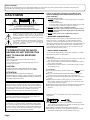
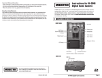
D-VHS DIGITAL SATELLITE RECORDER
HM-DSR100U
HM-DSR100DU (with Antenna Kit)
HM-DSR100RU (without Antenna Kit)
SAT
TV D-VHS AUX
POWER
TV/VCR
MODE
MTP
NTSC
MENU
MUTE
UME
VOL
GU
ID
E
T
H
E
M
E
B
R
O
W
S
E
SELECT
CH
INFO
MENU
SELECT
D-VHS
L
IN
E
FO
NC
CA
™INDEX VIEW INDEX£
1
2
TM
Ä
CH
3
SKIP AUTO TRACK SKIP
4
5
REC
POWER
FF/BROWSE
REW/BROWSE
7
6
8
q
9
ADDRESS
REW
2
FF
3
RECALL
TV/VCR
0
8 EJECT
POWER
REC
PAUSE
TIMER
EP
COUNTER RESET
REC
PAUSE
STOP
6
5
PLAY
VIDEO (MONO)L–AUDIO–R
TM
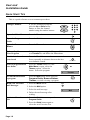
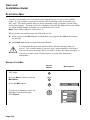
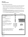
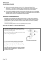
INSTRUCTIONS
For Customer Use:
Enter below the Serial No. which is
located on the rear of cabinet. Retain
this information for future reference.
Model No.
Serial No.
LPT0002-0H9C
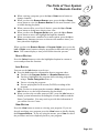
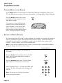
Dear Customer,
Thank you for purchasing the JVC D-VHS digital satellite recorder. Before use, please read the safety information and precautions
contained in the following pages to ensure safe use of your new VCR.
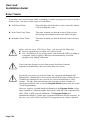
CAUTIONS
CAUTION
RISK OF ELECTRIC SHOCK
DO NOT OPEN
CAUTION:
TO REDUCE THE RISK OF ELECTRIC SHOCK.
DO NOT REMOVE COVER (OR BACK).
NO USER-SERVICEABLE PARTS INSIDE.
REFER SERVICING TO QUALIFIED SERVICE PERSONNEL.
The lightning flash with arrowhead symbol, within an equilateral
triangle, is intended to alert the user to the presence of
uninsulated "dangerous voltage" within the product's enclosure
that may be of sufficient magnitude to constitute a risk of electric
shock to persons.
The exclamation point within an equilateral triangle is intended to
alert the user to the presence of important operating and
maintenance (servicing) instructions in the literature
accompanying the appliance.
WARNING:
Failure to heed the following precautions may
result in damage to the VCR, remote control or
video cassette.
1. DO NOT place the VCR . . .
... in an environment prone to extreme temperatures or humidity.
... in direct sunlight.
... in a dusty environment.
... in an environment where strong magnetic fields are generated.
... on a surface that is unstable or subject to vibration.
2. DO NOT block the VCR’s ventilation openings.
3. DO NOT place heavy objects on the VCR or remote control.
4. DO NOT place anything which might spill on top of the VCR
or remote control.
5. AVOID violent shocks to the VCR during transport.
**MOISTURE CONDENSATION
Moisture in the air will condense on the VCR when you move it
from a cold place to a warm place, or under extremely humid
conditions—just as water droplets form on the surface of a glass
filled with cold liquid. Moisture condensation on the head drum will
cause damage to the tape. In conditions where condensation may
occur, keep the VCR’s power turned on for a few hours to let the
moisture dry before inserting a tape.
TO PREVENT FIRE OR SHOCK
HAZARD, DO NOT EXPOSE THIS
UNIT TO RAIN OR MOISTURE.
**ABOUT HEAD CLEANING
CAUTION:
How to Use
Use the optional head cleaning cassette DFC-2 if there is a sudden
deterioration in picture or sound quality.
CAUTION:
1. Insert the head cleaning cassette into your recorder. Press Play and
then wait for about 15 seconds before pressing Stop.
2. Eject the head cleaning cassette. Insert a D-VHS tape to confirm
picture and sound quality.
3. If deterioration in either picture or sound quality remains, repeat
the cleaning process.
TO PREVENT ELECTRIC SHOCK, MATCH WIDE
BLADE OF PLUG TO WIDE SLOT, FULLY INSERT.
CAUTIONS
This video cassette recorder should be used with AC
120V`, 60Hz only.
To prevent electric shocks and fire hazards, DO NOT use
any other power source.
ATTENTION:
POUR ÉVITER LES CHOCS ÉLECTRIQUES,
INTRODUIRE LA LAME LA PLUS LARGE DE LA FICHE
DANS LA BORNE CORRESPONDANTE DE LA PRISE ET
POUSSER JUSQU'AU FOND.
Note to CATV system installer:
This reminder is provided to call the CATV system installer's
attention to Article 820-40 of the NEC that provides guidelines
for proper grounding and, in particular, specifies that the cable
ground shall be connected to the grounding system of the
building, as close to the point of cable entry as practical.
CAUTION:
Changes or modifications not approved by JVC could void
user's authority to operate the equipment.
n Use only head cleaning cassettes marked with a
mark on
this unit.
n Do not rewind the head cleaning cassette halfway through the
cleaning process; rewind only after it has reached the end.
n Do not use the head cleaning cassette for longer than 15 seconds
at a time.
n If there is deterioration in either picture or sound quality after
three cleaning attempts, the problem may not be caused by dirty
heads. Please consult your dealer.
n The head cleaning cassette may be used approximately 100 times.
n The head cleaning cassette can not be used for recording or
playback.
DISH NetworkTM is a trademark of Echostar Communications
Corporation.
MTP
NTSC
This product incorporates copyright protection technology that is
protected by U.S. patents and other intellectual property rights.
Use of this copyright protection technology must be authorized
by Macrovision, and is intended for home and other limited payper-view uses only unless otherwise authorized by Macrovision.
Reverse engineering or disassembly is prohibited.
Page i
n Cassettes marked "D-VHS" and "VHS" can be used with this
video cassette recorder. However, D-VHS recordings are possible
only with cassettes marked "D-VHS".
n HQ VHS is compatible with existing VHS equipment.
n D-VHS tapes recorded on video products not using the D-VHS
MTP/NTSC standard cannot be played back on this unit.
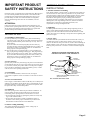
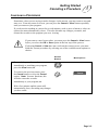
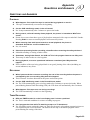
IMPORTANT PRODUCT
SAFETY INSTRUCTIONS
Electrical energy can perform many useful functions. But improper
use can result in potential electrical shock or fire hazards. This
product has been engineered and manufactured to assure your
personal safety. In order not to defeat the built-in safeguards,
observe the following basic rules for its installation, use and
servicing.
ATTENTION:
Follow and obey all warnings and instructions marked on your
product and its operating instructions. For your safety, please read
all the safety and operating instructions before you operate this
product and keep this booklet for future reference.
INSTALLATION
1. Grounding or Polarization
(A) Your product may be equipped with a polarized alternatingcurrent line plug (a plug having one blade wider than the other).
This plug will fit into the power outlet only one way. This is a
safety feature.
If you are unable to insert the plug fully into the outlet, try
reversing the plug. If the plug should still fail to fit, contact your
electrician to replace your obsolete outlet. Do not defeat the
safety purpose of the polarized plug.
(B) Your product may be equipped with a 3-wire grounding-type
plug, a plug having a third (grounding) pin. This plug will only
fit into a grounding-type power outlet. This is a safety feature.
If you are unable to insert the plug into the outlet, contact your
electrician to replace your obsolete outlet. Do not defeat the
safety purpose of the grounding-type plug.
2. Power Sources
Operate your product only from the type of power source indicated
on the marking label. If you are not sure of the type of power supply
to your home, consult your product dealer or local power company.
If your product is intended to operate from battery power, or other
sources, refer to the operating instructions.
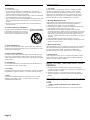
ANTENNA INSTALLATION
INSTRUCTIONS
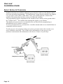
1. Outdoor Antenna Grounding
If an outside antenna or cable system is connected to the product, be
sure the antenna or cable system is grounded so as to provide some
protection against voltage surges and built-up static charges. Article
810 of the National Electrical Code, ANSI/NFPA 70, provides
information with regard to proper grounding of the mast and
supporting structure, grounding of the lead-in wire to an antenna
discharge unit, size of grounding connectors, location of antenna
discharge unit, connection to grounding electrodes, and
requirements for the grounding electrode.
2. Lightning
For added protection for this product during a lightning storm, or
when it is left unattended and unused for long periods of time,
unplug it from the wall outlet and disconnect the antenna or cable
system. This will prevent damage to the product due to lightning and
power-line surges.
3. Power Lines
An outside antenna system should not be located in the vicinity of
overhead power lines or other electric light or power circuits, or
where it can fall into such power lines or circuits. When installing an
outside antenna system, extreme care should be taken to keep from
touching such power lines or circuits as contact with them might be
fatal.
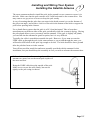
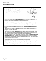
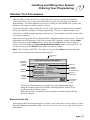
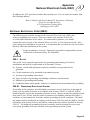
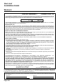
EXAMPLE OF ANTENNA GROUNDING AS PER
NATIONAL ELECTRICAL CODE, ANSI/NFPA 70
ANTENNA
LEAD IN WIRE
GROUND CLAMP
ELECTRIC SERVICE
EQUIPMENT
GROUNDING
CONDUCTORS
(NEC SECTION 810-21)
3. Overloading
Do not overload wall outlets, extension cords, or integral
convenience receptacles as this can result in a risk of fire or electric
shock.
ANTENNA
DISCHARGE UNIT
(NEC SECTION
810-20)
GROUND CLAMPS
POWER SERVICE GROUNDING ELECTRODE SYSTEM
(NEC ART 250. PART H)
NEC – NATIONAL ELECTRICAL CODE
4. Power Cord Protection
Power supply cords should be routed so that they are not likely to be
walked on or pinched by items placed upon or against them, paying
particular attention to cords at plugs, convenience receptacles, and
the point where they exit from the product.
5. Ventilation
Slots and openings in the cabinet are provided for ventilation. To
ensure reliable operation of the product and to protect it from
overheating, these openings must not be blocked or covered.
• Do not block the openings by placing the product on a bed, sofa,
rug or other similar surface.
• Do not place the product in a built-in installation such as a
bookcase or rack unless proper ventilation is provided or the
manufacturer’s instructions have been adhered to.
6. Wall or Ceiling Mounting
The product should be mounted to a wall or ceiling only as
recommended by the manufacturer.
Page ii
USE
SERVICING
1. Accessories
1. Servicing
To avoid personal injury:
• Do not place this product on an unstable cart, stand, tripod,
bracket, or table. It may fall, causing serious injury to a child or
adult, and serious damage to the product.
• Use only with a cart, stand, tripod, bracket, or table recommended
by the manufacturer or sold with the product.
• Use a mounting accessory recommended by the manufacturer and
follow the manufacturer’s instructions for any mounting of the
product.
• Do not try to roll a cart with small casters across thresholds or
deep-pile carpets.
If your product is not operating correctly or exhibits a marked
change in performance and you are unable to restore normal
operation by following the detailed procedure in its operating
instructions, do not attempt to service it yourself as opening or
removing covers may expose you to dangerous voltage or other
hazards. Refer all servicing to qualified service personnel.
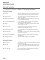
2. Product and Cart Combination
A product and cart combination should be
moved with care. Quick stops, excessive
force, and uneven surfaces may cause the
product and cart combination to overturn.
PORTABLE CART WARNING
(Symbol provided by RETAC)
3. Water and Moisture
Do not use this product near water—for example, near a bath tub,
wash bowl, kitchen sink or laundry tub, in a wet basement, or near a
swimming pool and the like.
4. Object and Liquid Entry
Never push objects of any kind into this product through openings
as they may touch dangerous voltage points or short-out parts that
could result in a fire or electric shock. Never spill liquid of any kind
on the product.
5. Attachments
Do not use attachments not recommended by the manufacturer of
this product as they may cause hazards.
6. Cleaning
Unplug this product from the wall outlet before cleaning. Do not use
liquid cleaners or aerosol cleaners. Use a damp cloth for cleaning.
7. Heat
The product should be situated away from heat sources such as
radiators, heat registers, stoves, or other products (including
amplifiers) that produce heat.
2. Damage Requiring Service
Unplug this product from the wall outlet and refer servicing to
qualified service personnel under the following conditions:
a. When the power supply cord or plug is damaged.
b. If liquid has been spilled, or objects have fallen into the product.
c. If the product has been exposed to rain or water.
d. If the product does not operate normally by following the
operating instructions. Adjust only those controls that are covered
by the operating instructions as an improper adjustment of other
controls may result in damage and will often require extensive
work by a qualified technician to restore the product to its normal
operation.
e. If the product has been dropped or damaged in any way.
f. When the product exhibits a distinct change in performance—this
indicates a need for service.
3. Replacement Parts
When replacement parts are required, be sure the service technician
has used replacement parts specified by the manufacturer or have
the same characteristics as the original part. Unauthorized
substitutions may result in fire, electric shock or other hazards.
4. Safety Check
Upon completion of any service or repairs to this product, ask the
service technician to perform safety checks to determine that the
product is in safe operating condition.
HOW TO USE THIS INSTRUCTION
MANUAL
● All major sections and subsections are listed in the Table Of
Contents on page iv. Use this when searching for information on a
specific procedure or feature.
● The Index on pages I–1 lists frequently-used terms, and the
number of the page on which they are used or explained in the
manual.
BEFORE YOU INSTALL YOUR NEW
VCR . . .
. . . please read the sections/literature listed below.
● ”Cautions”
● ”Important Products Safety Instructions” on the previous pages
Page iii
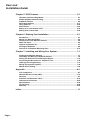
Table of Contents
T
Important Product Safety Instructions .................................................... ii
Chapter 1: Introduction .......................................................................... 1-1
Welcome! .................................................................................................................... 1-1
Highlights ................................................................................................................... 1-1
About Satellite Television ......................................................................................... 1-2
About D-VHS .............................................................................................................. 1-3
Unique All-In-One Design ......................................................................................... 1-3
If You Are Installing Your System Yourself ............................................................. 1-3
Features Overview .................................................................................................... 1-4
Available Services ..................................................................................................... 1-5
Quick Start Tips ......................................................................................................... 1-6
Chapter 2: The Parts of Your System ................................................... 2-1
The Recorder ............................................................................................................. 2-1
The Remote Control .................................................................................................. 2-7
The Satellite Antenna .............................................................................................. 2-14
Chapter 3: Getting Started ..................................................................... 3-1
Using the Remote Control ........................................................................................ 3-1
Turning On the System ............................................................................................. 3-4
Changing Channels ................................................................................................... 3-4
Canceling a Procedure ............................................................................................. 3-5
About Menus and Other Multiple-Choice Screens ................................................. 3-6
The Main Menu ........................................................................................................ 3-10
The System Setup Menu ......................................................................................... 3-10
Local TV Link ........................................................................................................... 3-13
Chapter 4: Using the System................................................................. 4-1
About the Program Banner ...................................................................................... 4-1
About the Browse Banner ........................................................................................ 4-3
About the Program Guide ......................................................................................... 4-6
About Themes ......................................................................................................... 4-11
Ordering Pay Per View Programs .......................................................................... 4-13
Favorites Lists ......................................................................................................... 4-14
Security Features .................................................................................................... 4-19
Electronic Mail ......................................................................................................... 4-30
Software Upgrades .................................................................................................. 4-31
Viewing Programs In Other Languages ................................................................ 4-33
Setting Up Channel Order ...................................................................................... 4-35
Diagnostic Tests ...................................................................................................... 4-36
Programming the Remote Control ......................................................................... 4-39
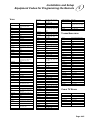
Equipment Codes for Programming the Remote ................................................. 4-44
Page iv
User and
Installation Guide
Chapter 5: VCR Features ....................................................................... 5-1
Cassettes and Recording Modes ............................................................................. 5-1
Simple Playback and Recording .............................................................................. 5-1
Playback Features ..................................................................................................... 5-6
Recording Features ................................................................................................. 5-17
Using Caller ID ......................................................................................................... 5-20
Event Timers ............................................................................................................ 5-22
Editing to or from Another VCR ............................................................................. 5-33
Editing from a Camcorder ...................................................................................... 5-34
Chapter 6: Starting Your Installation .................................................... 6-1
Introduction ............................................................................................................... 6-1
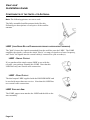
Before You Start Installation .................................................................................... 6-3
Components of the Satellite Antenna ...................................................................... 6-4
What You Need .......................................................................................................... 6-6
Optional Installation Kit ............................................................................................ 6-7
Finding the Satellites ................................................................................................ 6-9
Discussion of Potential Mounting Sites ................................................................ 6-13
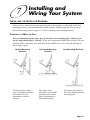
Chapter 7: Installing and Wiring Your System ..................................... 7-1
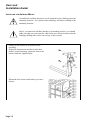
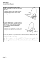
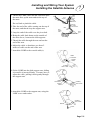
Installing the Satellite Antenna ................................................................................ 7-1
Grounding and Wiring the Satellite Antenna .......................................................... 7-8
Aiming the Antenna For the Strongest Signal ...................................................... 7-12
Connecting the Recorder to a Telephone Line ..................................................... 7-15
Ordering Your Programming .................................................................................. 7-17
Wiring Your System Together ................................................................................. 7-18
Manual Clock Setting .............................................................................................. 7-25
Appendix .................................................................................................A-1
FCC Compliance ....................................................................................................... A-1
National Electrical Code (NEC) ............................................................................... A-3
Glossary .................................................................................................................... A-7
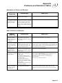
Problems and Solutions Tables ............................................................................ A-10
Questions and Answers ......................................................................................... A-23
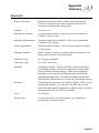
Specifications ......................................................................................................... A-24
For Servicing .......................................................................................................... A-25
Warranty .................................................................................................................. A-26
Index ......................................................................................................... I-1
Page v
1
Introduction
WELCOME!
Congratulations on your selection of this satellite television system. Thank you for your
purchase. You will be pleased with the performance, capabilities, entertainment options,
and ease of operation of your system for many years to come.
Your system complies with MPEG II and DVB standards for compressing audio and video
data. Your system also features an advanced new recording technology called D-VHS,
which records digital MPEG II satellite signals as digital data.
This means that the system will be compatible with new technologies in consumer
electronic products as they arrive on the market, including DVD Video Disc players and
data communication networks.
FOR MORE INFORMATION:
To subscribe to programming, or for assistance with installing or using the system, call
the DISH Network Service Center at 1-800-333-3474, or see the DISH Network's home
page at http://www.dishnetwork.com on the World Wide Web.
For warranty service, or for information about the features and operation of the HMDSR100DU/RU call JVC at 1-800-252-5722.
For more information on JVC products, see JVC's home page at http://www.jvc.com on the
World Wide Web.
HIGHLIGHTS
You have purchased the most advanced, easy-to-use satellite dish system available today.
Here is a list of some of the features that make this system powerful, yet simple enough for
anyone to use:
l Bit Stream (D-VHS) Recording: The recorder features the new D-VHS format
which records digital satellite broadcasts as digital signals, so programs can be recorded
"as is" with no loss of quality.
l IRR (Integrated Receiver-Recorder): This HM-DSR100, which is commonly
referred to as "recorder" in this manual, is actually an integrated unit which has a
satellite receiver, VHF/UHF receiver, and video recorder (VHS and D-VHS formats)
built in. This all-in-one design greatly simplifies set-up and operation of the unit.
l Easy Timer Programming: DISH Network's Program Guide provides an easy way
to look through all the programs currently being broadcast by DISH NetworkTM , and
even lets the user program the built-in VCR's timer to record any program on the list by
choosing it.
l UHF/IR Universal Remote Control : The UHF remote, you can use the remote to
control the recorder from another room, or even from another floor in the building. The
IR remote uses infrared light to control the TV, audio components, and other compatible
equipment.
l Local TV Link: In the past you had to compromise quality, or use external switching
devices to select between the satellite channels and your local broadcast channels. Now
you can attach the TV antenna or cable line directly and access those channels using the
Program Guide, the same way you access satellite channels.
Page 1-1
User and
Installation Guide
ABOUT SATELLITE TELEVISION
Satellite television uses satellites orbiting in geosynchronous orbit over the Earth to deliver
television and audio programming. "Geosynchronous" means that the satellites stay aligned
over one place on the surface of the Earth. Once your satellite antenna is aimed at the
satellites, the antenna does not have to move to follow the satellites.
The programming signal is transmitted to the satellites from a facility on the ground called
the "Uplink Center." The satellites then transmit the signal to your antenna.
The signal your system receives is customized for you based on the programming or
information services you have ordered.
To receive network services, you must have a satellite antenna and receiver installed that are
compatible with the network.
To order pay per view programs using your system, you must connect the recorder to an
active telephone connection. The recorder stores information on your pay per view
purchases, and transmits this information to the Service Center every few days.
Satellites
Your Location
Uplink Center
Telephone Connection
Service Center
Page 1-2
Introduction
About D-VHS
1
ABOUT D-VHS
The "D" in D-VHS represents Digital Data. As this name suggests, D-VHS is an extension
of the world's most popular VHS home video format, which adds new digital recording
(storage) capabilities that make it an ideal match for digital broadcasts.
Like VHS, D-VHS is a tape-based format. Unlike VHS, D-VHS records digital signals as a
digital bit stream (data) which is compatible with the MPEG II and DVB standards utilized
by your satellite system. Since digital data is stored "as is", there is no loss of quality
compared to the original satellite broadcast. D-VHS also offers high capacity, enabling
"storage" of up to 5 hours of recorded material per cassette.
And since you will want to continue enjoying all of the regular VHS tapes you've recorded
or accumulated, the D-VHS also offers conventional analog (VHS) recording and playback
in addition to digital.
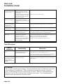
The relationship between type of broadcast, cassette used, and resulting recording is as follows:
Broadcast
Digital Satellite
Cassette
D-VHS
Recording
D-VHS (bit stream)
Digital Satellite
VHS
VHS (analog)
Local
D-VHS
VHS (analog)
Local
VHS
VHS (analog)
Notes:
l Recording on Super VHS tape:
Make sure you turn the "D-VHS" recording mode off if you intend to record a digital
satellite recording on a S-VHS cassette. We recommend that you only record digital "bit
stream" signals on D-VHS cassettes.
l Playing back D-VHS recording made on other D-VHS VCRs:
D-VHS recordings made on other VCRs may not playback on your JVC VCR. This is
because other D-VHS VCRs may record satellite signals from a system that is not
compatible with your DVB/MPEG II DISH system.
UNIQUE ALL-IN-ONE DESIGN
In addition to the two-way D-VHS/VHS capabilities of the built-in VCR, the recorder offers
expanded viewing options with simplified operation thanks to the two built-in tuners.
Incorporated into the recorder unit are a satellite receiver for satellite broadcast reception,
and a VHF/UHF tuner for local broadcast reception. This all-in-one design serves to
simplify the connections necessary for installation, and makes recording and viewing
operations easier too.
IF YOU ARE INSTALLING YOUR SYSTEM YOURSELF
If you are installing your system yourself, Chapters 6 and 7 describe how to unpack and
install the antenna and recorder. There is also an optional installation kit available. To buy
the installation kit, contact the location where you purchased your system or call the Service
Center. See What You Need on page 6-6 for more information.
Page 1-3
User and
Installation Guide
FEATURES OVERVIEW
For more detailed information, see Chapter 2 – The Parts of Your System.
STANDARD FEATURES
l Recorder
The IRR (Integrated Receiver-Recorder) features an allin-one design that makes it easy to install and operate.
l Remote Control
This remote control is specifically designed for easy
access to the menus.
l Simple Menu Operation
Simple "highlight and select" options allow quick, easy
navigation and programming.
l On-Screen Program Guide
Use the Program Guide to find out about upcoming
events and order special programs.
l Themes
You can display a list of those programs within a theme,
such as movies or sports.
l Favorites Lists
Favorites Lists let you set up a list of your favorite
channels for faster channel selection.
l System/Parental Locks
Prevent your kids from viewing programs you deem
unsuitable.
l Electronic Mail
Occasionally, you may receive electronic mail regarding
new features or services.
l Audio-only Programming
A number of channels feature commercial free audioonly programs.
l CD-Quality Sound
The best possible sound quality is available.
ADVANCED FEATURES
l Event Timers
Some systems can alert you when a program you want to
watch is about to start.
l Caller ID
If you have Caller ID through your phone company, use
this system to display the Caller ID information on your
TV.
l Local TV Link
Use Local TV Link to add local broadcast or cable TV
channels to the Program Guide.
Page 1-4
Introduction
Available Services
1
AVAILABLE SERVICES
Your system is capable of receiving a wide range of exciting and entertaining services.
The available services encompass an unlimited variety of interests, including movies,
sports, news, music, shopping, comedy, and more. Call the Service Center for more
information on any of these.
l Subscription Services are program channels or services that you purchase for extended
periods; they are billed at regular intervals; they remain activated until you call the
Service Center to terminate them.
l Package Services are groups of services offered to you at a discount; they provide the
greatest value to you because they combine the services that you wish to activate at a
reduced rate.
l One-Time Services are special broadcast events and other purchases you use once;
they include pay per view programs, installation and repair charges, and merchandise
purchases.
n A Pay Per View program is one that you buy once, and that is billed once on your
account for a single viewing; the fee varies depending on the specific program you
purchase, and is added to your next invoice.
n Installation, Activation, and Repair Services are one-time, non-broadcast charges
billed to your account following the completion of a service, such as when an
authorized technician installs your system or when an authorized repair facility
performs non-warranty repairs on your equipment (see Limited Warranty on page
A–26 for more information).
n Merchandise Services are shop-from-home products that you purchase via the
Service Center; they provide you with an easy and convenient way to purchase a
wide array of consumer products.
n Local TV link in addition to the wide range of satellite services you can receive
broadcast or cable TV channels.
Page 1-5
User and
Installation Guide
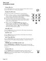
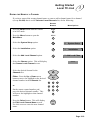
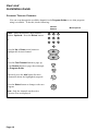
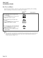
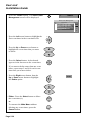
QUICK START TIPS
This is a quick reference to start common procedures:
Change Channels
If you are watching a program,
press the Up or Down arrow
button, or enter the channel
number using the number buttons.
1
2
3
4
5
6
7
8
9
0
Open the Main Menu
Press the Menu button.
MENU
Open the Program
Guide
Press the Guide button.
GU
ID
E
Open the Browse
Banner
Press the Browse button.
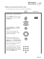
Order a Pay Per
View Program
Select the program using the Program Guide
or a Themes list, and follow the instructions.
See the last channel
you viewed
Press the Recall button on the remote control.
Press repeatedly to alternate between the last
two channels viewed.
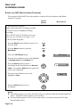
Select a program based
on a theme
B
R
O
W
S
E
Press the Theme button, or if the
Main Menu is open, select the
Themes option. Select the
theme. Select the program.
T
H
E
M
E
2
See information about
a program
Read your electronic
mail messages
Press the Info button while using the
Program Guide, Browse Banner,
Themes, or while viewing a program.
1. Press the Menu button.
RECALL
COUNTER RESET
or
Themes
IN
FO
MENU
2. Select the Mail option.
3. Select the mail message.
3
Mail
4. Delete the mail message after
reading.
Activate a Favorites
List
1. Press the Guide button to open the
Program Guide.
2. Press the Guide button again to
select the next Favorites List.
Page 1-6
GU
ID
E
The Parts of
Your System
2
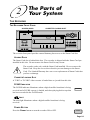
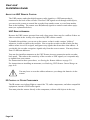
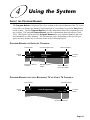
T HE RECORDER
THE RECORDER FRONT PANEL
ACCESS DOOR
CASSETTE LOADING SLOT
CH
INFO
MENU
SELECT
D-VHS
Ä
TM
REC
POWER
q
TV/VCR
8 EJECT
POWER
REC
PAUSE
TIMER
REW
2
CH
FF
3
EP
PAUSE
STOP
6
5
PLAY
VIDEO (MONO)L–AUDIO–R
The recorder front panel provides control buttons, plus access to the Smart Card slot.
ACCESS DOOR
The Smart Card slot is behind this door. The recorder is shipped with the Smart Card preinstalled in this slot. Do not remove the Smart Card for any reason.
The recorder works only with the Smart Card installed. Do not remove the
Smart Card. Keep the access door closed to prevent damage to the Smart
Card. The Limited Warranty does not cover replacement of Smart Cards that
you lose or damage.
CASSETTE LOADING SLOT
A "VHS" or "D-VHS" video cassette is loaded into or ejected from this slot.
D-VHS INDICATOR
The D-VHS indicator illuminates when a digital satellite broadcast is being
received and a D-VHS cassette is loaded, and when playing back a tape that
has been recorded in the D-VHS mode.
TM
D-VHS
LIGHT
The dish light illuminates when a digital satellite broadcast is being
received.
TM
POWER BUTTON
Press the Power button to turn the recorder ON or OFF.
POWER
Page 2-1
User and
Installation Guide
POWER LIGHT
The POWER light illuminates when the recorder is turned ON.
This light flashes when the recorder memory contains
unread mail messages.
POWER
REC LIGHT
The REC light illuminates while a tape is being recorded.
This light blinks during Instant Timer Recording (ITR).
PAUSE LIGHT
REC
PAUSE
The PAUSE light illuminates when recording or playback is paused.
TIMER LIGHT
The TIMER light illuminates to show that the recorder's timer has
been set to record a program automatically.
TIMER
EP LIGHT
The EP light illuminates during recording or playback in the EP
(Extended Play) mode.
EP
INFO BUTTON
The Info button displays information about a program or about the
system, depending on what you are currently viewing.
INFO
MENU
Press the Menu button to open the Main Menu.
MENU
UP/DOWN/LEFT/RIGHT ARROW BUTTONS
These buttons change the channel numbers move the highlight when in
a menu or other screen.
From a program, the Up/Down buttons change channels; the Left/Right
buttons display other menus.
CH
Ä
CH
SELECT BUTTON
Press the Select button to select a highlighted menu option and
perform that function.
Page 2-2
SELECT
The Parts of Your System
The Recorder
2
TV/VCR BUTTON
Press the TV/VCR button to select the signal source that your TV
receives. Choose TV position to watch TV or to watch one program
while recording another. Choose VCR position to watch a tape, monitor
a recording, or watch a satellite or local TV broadcast being received
by the recorder.
TV/VCR
EJECT BUTTON
Press the EJECT button to eject a cassette from the cassette loading slot.
8 EJECT
REC BUTTON
Press the REC (Record) button to start recording on a tape.
REC
q
REW BUTTON
Press the REW (Rewind) button to rewind the tape at high speed.
Also, during playback of a VHS recording, press this button to view
the picture in rapid reverse visual search.
REW
2
FF BUTTON
Press the FF (Fast Forward) button to move the tape forward at high
speed. Also, during playback of a VHS recording, press this button to
view the picture in rapid forward visual search.
FF
3
PAUSE BUTTON
Press the PAUSE button once to temporarily stop the tape during
recording. During playback, press this button to freeze the playback
picture, and press again to advance the picture by one frame.
PAUSE
6
STOP BUTTON
Press the STOP button to stop the tape.
STOP
5
PLAY BUTTON
Press the PLAY button to play a tape.
PLAY
AUXILIARY PHONO (RCA) AUDIO/VIDEO INPUT
Connect other auxiliary equipment (such as a DVD or laserdisc
player) to this phono (RCA) input to get the best available audio and
video. Tune to channel 000 to view sources connected to this input.
VIDEO (MONO)L–AUDIO–R
Page 2-3
User and
Installation Guide
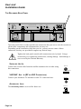
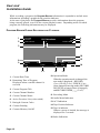
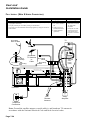
THE RECORDER BACK PANEL
AC`IN
HIGH SPEED DATA PORT
DC OUT 5V
1
ANT. IN
OUT
2
PHONE JACK
ACCESSORY AC-3
13/18V}400mA
SATELLITE
R
S-VIDEO
L
AUDIO
VHF/UHF
ANT. IN
VIDEO
UHF
REMOTE
ANTENNA
RF OUT
CH3
CH4
The back panel of the recorder provides the connectors that you use to wire the recorder to
all the other components and equipment that you may use.
Depending on the installation setup that you use, you may not use some of these
connectors, but they are provided to support any desired setup.
Tighten the back panel coaxial cable connections only by hand. Using a
wrench may over-tighten the connections, causing damage. Such damage is
not covered by the Limited Warranty.
SATELLITE ANT. IN
Connect the coaxial cable from the satellite antenna to the recorder using
this connection.
ANT. IN
13/18V}400mA
SATELLITE
VHF/UHF ANT. IN (RF OR VHF CONNECTION)
Connect your broadcast TV antenna or cable TV connection here.
VHF/UHF
ANT. IN
ACCESSORY JACK
The Accessory Jack is reserved for future use.
DC OUT 5V
ACCESSORY
Page 2-4
The Parts of Your System
The Recorder
2
RF OUT (RF OR VHF CONNECTION)
RF OUT
The recorder sends non-stereo output through this connector. If you are
connecting cable TV or a broadcast TV antenna to the recorder, use this
connection to connect to the TV for good picture and good non-stereo
sound. Use the TV Phono (RCA) Audio/Video Output or the S-VIDEO
Output to support the highest quality stereo sound and video for your
satellite channels. See RF or VHF Connections (Good Picture and
Sound) on page 7-19 for more information.
PHONO (RCA) AUDIO/VIDEO OUTPUTS
Connect one set of these phono (RCA) connections to a second VCR
for editing and connect one set of these phono (RCA) connections to
your TV to obtain the best available audio and video from your
recorder.
1
OUT
2
R
L
AUDIO
VIDEO
S-VIDEO OUTPUT
The recorder supports S-VIDEO, which provides the highest quality
video available. If you use this connector, you still need to connect the
audio using the phono (RCA) audio outputs.
S-VIDEO
UHF REMOTE ANTENNA
The recorder uses the UHF antenna to receive commands from
the remote.
Note: Place the antenna vertically for maximum remote range.
If necessary for space you can place the antenna horizontally,
but this may reduce the range.
UHF
REMOTE
ANTENNA
Make sure that the UHF antenna is not touching any metal surface
or objects.
CHANNEL 3/4 SWITCH
If you use the RF OUT connection to wire the recorder to your
television, you will need to move this switch to the channel to which
the recorder will send the programming signal. Select a channel that
is not being used by a cable or local television station.
Note: It is not possible to operate the CHANNEL 3/4 switch through the
menu screen. Use the CHANNEL 3/4 switch located on the back panel of
this unit.
CH3
CH4
Page 2-5
User and
Installation Guide
AC-3 (DOLBY DIGITAL OUTPUT)
By connecting this output terminal to an external decoder, you can enjoy
Dolby Digital (AC-3) 5.1-channel surround sound when viewing
appropriately encoded satellite broadcasts or recorded tapes.
AC-3
l Dolby, Dolby Digital, AC-3, Dolby Pro Logic are registered trademarks or Dolby
Laboratories Licensing Corporation.
HIGH SPEED DATA PORT
There is a high speed data port under the cover plate.
This port is reserved for use with new technologies,
such as high speed data networks, as they become
available.
HIGH SPEED DATA PORT
Do not remove the plate covering the High Speed Data Port until you need to
use the port. Damage to an exposed port is not covered by the Limited
Warranty.
TELEPHONE JACK
Connect a telephone line with a standard RJ-11 telephone connector to
the recorder here, and then connect the line to an active telephone
connection.
PHONE JACK
Your recorder must be connected to a telephone line at all times to order pay
per view programs.
Page 2-6
The Parts of Your System
The Remote Control
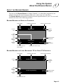
2
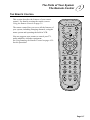
THE REMOTE CONTROL
This section describes the features of your remote
control. For details on using the remote, turn to
Using the Remote Control on page 3-1.
SAT
TV D-VHS AUX
POWER
TV/VCR
You can program your remote to control your TV,
audio amplifier, and other equipment.
See Programming the Remote Control on page 4–39
for this procedure.
MODE
MENU
MUTE
UME
VOL
T
H
E
M
E
GU
ID
E
B
R
O
W
S
E
SELECT
IN
FO
L
The remote control lets you access all the features of
your system, including changing channels, using the
menu system and operating the built-in VCR.
E
NC
CA
™INDEX VIEW INDEX£
1
2
3
SKIP AUTO TRACK SKIP
4
5
FF/BROWSE
REW/BROWSE
7
6
8
9
ADDRESS
RECALL
0
COUNTER RESET
REC
Page 2-7
User and
Installation Guide
ABOUT THE UHF REMOTE CONTROL
The UHF remote sends ultra-high frequency radio signals to a UHF antenna that is
connected to the back of the recorder. Because UHF signals travel through solid objects,
you can use the remote to control the recorder from another room, or even from another
floor in the building. The remote uses IR(Infrared) signals to control certain other equipment (see explanation below).
UHF REMOTE ADDRESS
Because the UHF remote operates from such a long range, there may be conflicts if there are
other recorders in the vicinity, also operated by UHF remote controls.
To handle this problem, you can set up the remote so that it sends a unique "address"
whenever it sends a signal to the recorder. You set up the recorder so that it looks for that
address when it receives a signal, and ignores any signals that do not have that address. If
you do this, the recorder recognizes signals only from the correct remote. You may choose
from 15 different addresses.
You can also install an attenuator at the UHF Remote Antenna connection on the recorder
back panel. This reduces the sensitivity of the recorder to UHF signals, so it responds only
to signals from your remote.
For instructions on these procedures, see Setting the Remote Address on page 3-2.
For instructions on installing an attenuator, see Reducing UHF Remote Control Range on
page 4-41.
You may have to reset the address whenever you change the batteries in the
remote.
IR CONTROL OF OTHER COMPONENTS
The IR remote uses infrared light to control the TV, audio components, and other compatible
equipment, instead of UHF radio signals.
You must point the remote directly at the component, with no solid objects in the way.
Page 2-8
The Parts of Your System
The Remote Control
2
REMOTE BUTTONS
TV/VCR BUTTON
Depending on how you wire your system together, the TV/VCR button
does the following:
l In SAT (Satellite) mode, the TV/VCR button switches the TV
connected to the RF or VHF output between satellite TV and
broadcast or cable TV. However, the Local TV Link feature is an
easier way to view both satellite programming and local broadcast
programming (see Local TV Link on page 3-13 for information).
l In D-VHS mode, the TV/VCR button acts the same as when in the
SAT mode.
l In TV mode, the TV/VCR button switches among the inputs
available on your TV.
TV/VCR
l The TV/VCR button can be used when controlling a receiver or
second VCR.
Note: The remote does not support this function for all TV's and VCR's.
POWER BUTTON
Press the Power button to turn the recorder ON or OFF. The power light
on the recorder illuminates to indicate the recorder is ON.
POWER
MODE BUTTON
You can use the Mode button to set the remote to control the recorder, its
built-in satellite tuner and other various electronic components, such as
TVs, VCRs, Stereo Amplifiers and Cable Boxes.
If you press the Mode button once, a mode light flashes rapidly to
indicate which mode the remote is using. Press the Mode button again
to change the mode to the next mode setting. See Programming the
Remote Control on page 4-39 for the procedure to program the remote
to control your TV, the built-inVCR, and other equipment.
The modes are as follows:
l In SAT (Satellite) mode the remote controls the built-in
satellite receiver. Some VCR functions are also
controllable.
l In TV mode the remote controls the TV.
l In D-VHS mode the remote controls the
built-inVCR. The buttons that can be used in the
D-VHS mode are labeled in green on the remote
control. Some tuner functions are also controllable.
l In AUX (Auxiliary) mode the remote controls another
electronic device. This can be a stereo amplifier,
second TV or a second VCR.
MODE
SAT
TV/VCR
TV D-VHS AUX
POWER
Page 2-9
User and
Installation Guide
MUTE BUTTON
Press the Mute button to temporarily activate the mute function on your
TV. Press the Mute button again to restore the sound.
MUTE
Note: This button works only if you have programmed the remote to
control a TV or a stereo amplifier. The Mute button changes the volume
at the corresponding electronic component, not at the recorder.
MENU BUTTON
Press the Menu button to open the Main Menu.
MENU
VOLUME BUTTON
Press the (+) side of the Volume button to increase the sound volume.
Press the (–) side of the Volume button to reduce the sound volume.
UME
VOL
Note: This button works only if you have programmed the remote to
control the TV or a stereo amplifier. The Volume button changes the
volume at that TV or amplifier.
GUIDE BUTTON
GU
ID
E
Press the Guide button to open the Program Guide.
UP/DOWN/LEFT/RIGHT ARROW BUTTONS
You can use the arrow buttons for several purposes:
l When you are using a menu, press the Up, Down, Left, or
Right arrow button to move the highlight to the desired option.
l When viewing a program or playing a digital (D-VHS) recording,
press the Right arrow button to open the Browse Banner.
l When viewing a program, press the Left arrow button to open the
Theme Categories menu.
Page 2-10
B
R
O
W
S
E
T
H
E
M
E
The Parts of Your System
The Remote Control
2
l When viewing a program, press the Up or Down arrow button to
change channels.
l When you have the Browse Banner open, press the Up or Down
arrow button to view the Browse Banner for the next channel. (Not
available during playback)
l When a menu offers you a list of choices, press the Up or Down
arrow button to bring more choices into view.
l When you have the Program Guide open, press the Up or Down
arrow button to move the highlight through the channels.
l When you must enter a number for a menu option, press the Up or
Down arrow button to increase or decrease the number where you
have placed the highlight.
When you have the Browse Banner or Program Guide open, press the
Left or Right arrow button to display programs in different time periods.
Note: You cannot display a time period earlier than the present.
SELECT BUTTON
Press the Select button to select the highlighted option in a menu or
screen and perform the function.
SELECT
INFO BUTTON
You can use the Info button several ways.
l Press the Info button for information about a program when:
n You have the Program Guide or a Browse Banner open,
n You have highlighted the program while selecting programs
using a Theme Categories menu, or
n You are viewing the program.
n You are palying back a bit stream (D-VHS) recording of the
program.
l When you have a menu open that contains a Help option, press the
Info button to see the help information for that menu.
l When you have the recorder powered OFF, press the Info button to
display system information, including the recorder address and the
Smart Card number. You may need to provide this information if
you call the Service Center.
IN
FO
VIEW BUTTON
Press the View button to return to viewing your program. If you are
already watching your program, press the View button to briefly display
the Program Banner. If you are using the menus, press View to cancel
the procedure and exit completely back to your program.
VIEW
Page 2-11
User and
Installation Guide
CANCEL BUTTON
L
Press the Cancel button to cancel the current procedure and to return to
the previous menu or to viewing your program.
CA
NUMBER P AD BUTTONS
You can use the number pad buttons for several purposes:
l When viewing a program or when the Program Guide is
open, enter the 3-digit channel number and press the Select
button to change immediately to that channel.
l Use these buttons to enter menu option numbers.
l If you are using a menu that requests some number such as
a ZIP code or a password, press the buttons on the number
pad to enter that information.
l When you have the Program Guide open, enter the
number of hours, and then press the Left or Right arrow
button to display programs in the time period offset by the
designated number of hours. Note: You cannot display a
time period earlier than the present.
E
INDEX£
™INDEX
1
NC
2
3
SKIP AUTO TRACK SKIP
4
5
REW/BROWSE
7
6
FF/BROWSE
8
9
0
INDEX BUTTONS
Press the Index buttons to use the built-in VCR's Index Search function.
See Index Search on page 5–8.
SKIP BUTTONS
Press the Skip buttons to use the built-in VCR's Skip Search function.
See Skip Search on page 5–7.
AUTO TRACK BUTTON
Press the Auto Track button to turn the built-in VCR's automatic tracking
function on or off. To adjust tracking manually, see Manual Tracking
on page 5–10.
REW/BROWSE AND FF/BROWSE BUTTONS
Press the REW/Browse or FF/Browse button to use the built-in VCR's
REW/Browse and FF/Browse functions. See REW/Browse and FF/Browse
on page 5–6.
ADDRESS BUTTON
Use the Address button to program the remote to control your TV, or
auxiliary device such as a second TV or VCR. You can also use the
Address button to set the remote address. See Programming the Remote
Control on page 4-39.
Page 2-12
ADDRESS
The Parts of Your System
The Remote Control
2
RECALL BUTTON/COUNTER RESET BUTTON
With the remote in the SAT mode, press the Recall button to go back to
the last channel you were watching. Press repeatedly to alternate
between the last two channels that you viewed.With the remote in the
D-VHS mode, and if there is a tape loaded in the recorder, press the
Counter Reset button to change the current tape counter reading to
"0:00:00".
RECALL
COUNTER RESET
REC(ORD) BUTTON
Press the Rec button to start recording a program. The D-VHS mode is
automatically activated if a satellite channel is selected and a D-VHS
cassette loaded in the VCR. This button is also used to activate the ITR
(Instant Timer Recording) function. See Instant Timer Recording
on page 5-19. You can also use the Rec button to match the recorder and
remote addresses. See Setting the Remote Address on page 3-2.
REC
FAST FORWARD BUTTON
With the remote in D-VHS mode, press the Fast Forward button to rapidly
advance the tape. During playback of an analog (VHS) recording, press this
button to rapidly view the video as a forward visual search. In SAT mode,
press this button to page up through the Program Guide or a Themes list.
REWIND BUTTON
With the remote in D-VHS mode, press the Rewind button to rewind the tape.
During playback of an analog (VHS) recording, press this button to rapidly
view the video as a reverse visual search. In SAT mode, press this button to
page down through the Program Guide or a Themes list.
PAUSE BUTTON
With the remote in D-VHS mode, press the Pause button to temporarily stop
the tape during recording or play. Press the Play button to restart the tape.
PLAY BUTTON
With the remote in D-VHS mode, press the Play button to play the video tape.
STOP BUTTON
With the remote in D-VHS mode, press the Stop button to stop the video tape.
Page 2-13
User and
Installation Guide
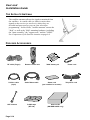
THE SATELLITE ANTENNA
The satellite antenna collects the signals transmitted from
the satellites. A coaxial cable (or cables) carries these
signals to the receiver (or receivers), where they are
decoded and processed so you can view television
programming. In this Guide, "satellite antenna" means the
"dish," as well as the "dish" mounting hardware, including
the "mast assembly," the "support arm," and the "LNBF."
See Components of the Satellite Antenna on page 6-4.
PROVIDED ACCESSORIES
SAT
TV D-VHS AUX
POWER
TV/VCR
MODE
MENU
MUTE
UME
VOL
T
H
E
M
E
GU
ID
E
B
R
O
W
S
E
SELECT
L
IN
E
FO
NC
CA
™INDEX VIEW INDEX£
1
2
3
SKIP AUTO TRACK SKIP
4
5
REW/BROWSE
7
6
FF/BROWSE
8
9
ADDRESS
RECALL
0
COUNTER RESET
REC
RF cable (F-type)
S-Video cable
(4-pin)
UHF antenna
Page 2-14
Remote control unit
Audio/Video cable
D-VHS tape
(DF-180)
"AAA" battery x 4
Smart card
(pre-installed in recorder)
Antenna Kit
(HM-DSR100DU only)
Power cord
Telephone cord
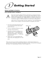
3
Getting Started
USING THE REMOTE CONTROL
INSTALLING BATTERIES IN THE REMOTE
The remote control is shipped with four AAA batteries, packaged separately.
When you replace old batteries, you should replace all four batteries. Use four
batteries of the same grade, for example, alkaline or carbon zinc, and do not
mix batteries of different grades. Alkaline batteries provide longer battery life.
Any time you remove or install the batteries, you may have to reprogram the
remote for the TV and any other electronic components. See Programming the
Remote Control on page 4-39 for the procedure to reprogram your remote.
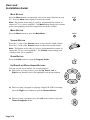
1. Press down on the slot in the battery case
cover (on the back of the remote) and
remove the cover.
Battery Cover
2. If you are replacing old batteries, remove
and replace all four batteries.
3. Insert the new batteries, making sure to
match the plus (“+”) ends with the plus
indicators on the remote. The batteries
alternate plus and minus (“–”) ends when
properly seated.
4. Replace the cover by inserting the tabs
into the slots, and snapping the cover into
place.
Back of
Remote
Batteries
If the remote does not work after installing the batteries, confirm that the batteries are
properly seated, with the plus and minus ends aligned correctly. You may need to reprogram
the remote. See Programming the Remote Control on page 4-39.
Page 3-1
User and
Installation Guide
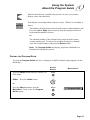
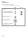
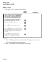
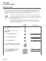
CHANGING MODES ON THE REMOTE
Use the Mode button to set the remote to control other electronic components, such as your
TV. See Mode Button on page 2-9 for more information. To change modes, do the following:
Press the Mode button on the remote
repeatedly until the appropriate mode
light flashes rapidly.
MODE
For example, to control the built-in
satellite receiver, make sure the SAT
light is flashing. Or for the D-VHS
mode, which is used to control the
built-in video recorder and local timer,
the D-VHS light should be flashing.
SAT
TV/VCR
TV D-VHS AUX
POWER
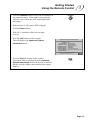
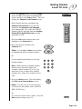
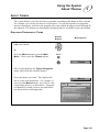
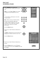
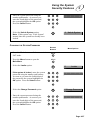
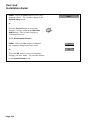
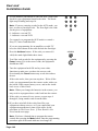
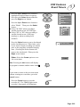
SETTING THE REMOTE ADDRESS
If your recorder turns ON or OFF, or does anything else without you pressing any buttons, it
may be responding to signals from another nearby remote control. To prevent undesired
operation of your recorder by a neighbor’s remote, you can address your remote to the
recorder. You may choose from 15 different addresses.
Note: If your remote is addressed to the recorder, you may need to reprogram this address
when you change the batteries in the remote.
Remote Buttons
1. Make sure that fresh batteries are installed in
the remote.
2. Press the Mode button until the remote is in SAT
mode. The SAT mode light flashes rapidly to
indicate the mode.
MODE
3. Press the Address button once. The SAT mode
light continues to flash, but at a slower rate.
4. Enter a number from 1 to 15 using the number pad
buttons. The SAT mode light stops flashing and
stays lit.
Note: Do not put a zero before the number
when entering this number.
Page 3-2
ADDRESS
1
2
3
4
5
6
7
8
9
0
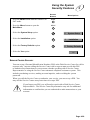
Getting Started
Using the Remote Control
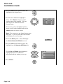
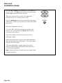
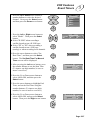
5. Press the Address button to save the new address in
the remote memory. If the address you entered is
valid for your remote, the SAT mode light blinks
three times.
3
ADDRESS
6. If the recorder is ON, turn it OFF using the
recorder Power button.
7. Wait for 15 seconds to allow the recorder
to reset.
8. Press the Info button on the recorder.
This will display the Important System
Information menu.
Important System Information
Model ID: IRR
Receiver CA ID: R0016825089-94
Smart Card CA ID: S0000278950-56
DNASP002 Rev052
Software Version: 205PBTAA-F
Boot Strap Version : 100BBTAA
Customer Service: 1-800-333-DISH (3474)
Internet Address: http://www.dishnetwork.com
Remote Address: 9
Copyright © 1996, EchoStar Communications
Corporation. All Rights Reserved.
9. Press the Rec(ord) button on the remote.
The remote address displayed on the Important
System Information menu will change to indicate
that the recorder address now matches the remote
address.
OK
REC
Page 3-3
User and
Installation Guide
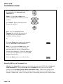
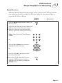
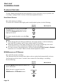
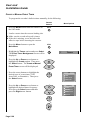
TURNING ON THE SYSTEM
Remote
Buttons
Menu Options
1. Turn ON the TV and any other installed
equipment.
2. Turn ON the recorder. The power light on the
recorder front panel illuminates.
POWER
Note: The remote must be in SAT mode to
use it to turn ON the recorder.
CHANGING CHANNELS
If the program you select to view is security locked, you must enter the system
password to view it.
Remote
Buttons
Menu Options
Either: Press the Up or Down arrow
button to change channels.
All unpurchased channels are
automatically skipped. You will see
only the channels in the active
Favorites List.
or
1
2
3
Enter the desired three-digit channel
number using the number pad buttons.
4
5
6
7
8
9
Note: When changing channels to a
channel number that has fewer than
three digits (for example channel
number 2 or 10), you must enter zeros
to make these channel numbers three
digits (for example 002 or 010).
Page 3-4
0
Getting Started
Canceling a Procedure
3
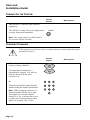
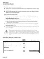
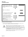
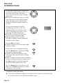
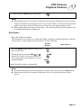
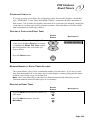
CANCELING A PROCEDURE
Sometimes, when you are trying to make changes via the menus, you may want to stop and
start over. From any menu or screen, you can press the Cancel or View button repeatedly
until you return to your program.
If you do not do anything in a menu for several minutes, such as press a button or select an
option, the menu automatically closes. This also discards any changes you made, and
returns the recorder to the program you were viewing.
If you want to cancel a procedure, you must press the Cancel or View button
before you select the OK or Save option in the last step of the process.
If selecting Cancel or View does not exit from the current screen, you must
finish the current procedure by selecting one of the available menu options or
choices.
Remote
Buttons
To return to the previous menu, press
the Cancel button or select the Cancel
option. Note: In some functions, this
will also return the recorder
immediately to your program, or
VIEW
Cancel
L
To cancel the procedure and return
immediately to watching your program,
press the View button, or
Menu Options
CA
N
CE
Wait a few minutes and the menu will
automatically close, discarding any changes
you have made.
Page 3-5
User and
Installation Guide
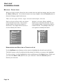
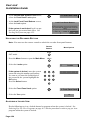
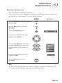
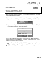
ABOUT MENUS AND OTHER MULTIPLE-CHOICE SCREENS
We designed the menus to make programming your recorder and selecting services quick
and easy. The recorder displays the menus on your TV screen (“on-screen”). You use
menus to communicate with the recorder and use the recorder features, such as setting
security locks, selecting a program, or defining a Favorites List. These features are
discussed in Chapter 4 - Using the System.
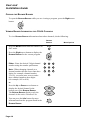
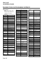
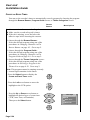
SYSTEM MENU STRUCTURE
The following figure shows the general structure of the menus you will see as you use the
system. As you can see, the Main Menu is the key to all other menus.
Main Menu
1 Program Guide
5
2 Themes
6 System Setup
3
7
Timers
8
VCR Setup
Mail
4 Favorites
0
Locks
Cancel
Return from this menu
Theme Categories
System Setup Menu
Parental and System Locks
1 Movies
5 Education
1 Installation
3 New Features
1 Ratings Locks
4 Front Panel Lock
2 Sports
6 Series/Specials
2 Diagnostics
4 Purchase Info
2 Channel Locks
5 Change Password
3 News/Business
7 Music/Arts
5 Preferences
3 Lock System
4 Family/Children
8 Religious
0
Cancel
0
Cancel
0
Return from this menu
Return from this menu
Installation and Setup Menu
User Preferences Menu
1 Point Dish/Signal
4Telephone System
1 Alternate Audio
3 Channel Order
2 Add Local Chan.
5 Factory Defaults
2 Picture Size
4 System Upgrades
3 System Info
5
0
0
Cancel
Return from this menu
Page 3-6
Cancel
Caller ID
Cancel
Return from this menu
Getting Started
About Menus and Other Multiple-Choice Screens
5
3
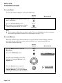
DISPLAYING MENUS
You can use either of two methods to open the menus.
l Open the Main Menu, then open any of the other menus from the Main Menu,
or
l Press the appropriate button on the remote to immediately open the desired menu.
MENU OPTIONS
A typical menu option looks like this:
or this:
OK
1
Program Guide
First you must highlight the menu option, then you select it.
HIGHLIGHTING A MENU OPTION
When you highlight a menu option using the arrow buttons on your remote, that option will
appear a little darker than the other options, and it will look “pushed in.”
A typical highlighted menu option looks like this:
or this:
OK
1
Program Guide
Once you have highlighted a menu option, you can select it.
SELECTING A MENU OPTION
When you select a menu option, that menu function is immediately performed. You press
the Select button once the menu option is highlighted.
A SHORTCUT
An easier way to select a menu option is just to display the menu, then, on the remote
control, press the number of that menu option (for example, “1” in the example above).
This performs the highlight and select functions all at once.
Page 3-7
User and
Installation Guide
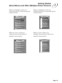
MULTIPLE - CHOICE LISTS
When you select a choice from a list, the recorder does not apply the change until you select
the Save or OK option. If you do not want to save any changes, select the Cancel option to
discard all changes made in the menu.
There are two types of lists: single selection and multiple selection.
Single-selection allows only one choice
to be selected at one time. If you select
another choice, the previous choice is
deselected. The single-choice list uses a
circle to identify the choice.
Multiple selection allows multiple
choices to be selected at one time. If you
select another choice, the previous choices
remain selected. The multiple-choice list
uses squares to identify the choice.
Languages
English
Spanish
Channels
FOX - 247
HBO-E - 300
CNN - 206
French
SHO-E - 310
German
MAX-E - 320
Italian
NBC - 241
Japanese
CBS - 243
HIGHLIGHTING AND SELECTING A CHOICE IN A LIST
Use the Up/Down arrow buttons on the remote to highlight the desired item in the list.
The black arrows on the list indicate the direction(s) in which you can move the highlight.
To select a choice in a list, highlight the choice and then press the Select button. Make sure
you select the Save or OK option to save your selection. Select the Cancel option to
discard your selection.
Page 3-8
Getting Started
About Menus and Other Multiple-Choice Screens
When you highlight a choice in a
single-selection list, it typically appears
as shown below:
Languages
English
Spanish
When you highlight a choice in a
multiple-selection list, it typically appears
as shown below:
Channels
FOX - 247
HBO-E - 300
CNN - 206
French
SHO-E - 310
German
MAX-E - 320
Italian
NBC - 241
Japanese
When you select a choice in a
single-selection list, the choice is
marked as shown below:
Languages
English
Spanish
CBS - 243
When you select choices in a
multiple-selection list, the choices are
marked as shown below:
Channels
FOX - 247
HBO-E - 300
CNN - 206
French
SHO-E - 310
German
MAX-E - 320
Italian
NBC - 241
Japanese
3
CBS - 243
Page 3-9
User and
Installation Guide
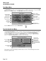
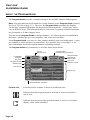
THE MAIN MENU
The Main Menu provides access to all the features available in the menus. To open the Main
Menu, press the Menu button. The Main Menu looks like the following.
Main Menu
Name of Menu
Opens Program
Guide Screen
1
Program Guide
5
Locks
Opens Theme
Categories Menu
2
Themes
6
System Setup
Opens Mail Menu
3
Mail
7
Timers
Opens Favorite
Lists Menu
Exit Viewed
Program
4
Favorites
8
VCR Setup
0
Opens Parental and
System Locks Menu
Opens System
Setup Menu
Opens Timers Menu
Opens VCR Setup
Menu
Cancel
Return from this menu
Press the Menu button to open the Main Menu.
Description of
Highlighted Option
MENU
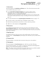
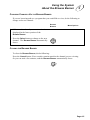
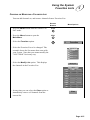
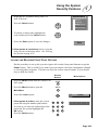
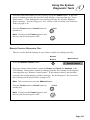
THE SYSTEM SETUP MENU
The System Setup Menu provides a number of functions that help you install, customize,
and get information about your system. You can display the System Setup Menu by
pressing the Menu button to display the Main Menu, then selecting the System Setup
option. The System Setup Menu is similar to the following.
System Setup Menu
Opens Installtion
Menu
Opens System
Dlagnostic Tests
Menu
Exit to Viewed
Program
1
Installation
3
New Features
2
Diagnostics
4
Purchase Info
5
Preferences
0
Displays New
Features Sent by
Service Center
Displays Most
Recent Dish-OnDemand Purchases
Opens Preferences
Menu
Cancel
Return from this menu
Each option on this menu displays another menu or screen. The following list describes
how these options work:
Page 3-10
Getting Started
The System Setup Menu
3
1 INSTALLATION
This option displays the Installation and Setup menu. You will use this menu most while
you are initially setting up your system.
l Use the Point Dish and Signal Strength menu to aim the satellite antenna.
Transponder refers to the channel transponder numbers that this unit receives.
Transponder numbers are automatically displayed.
ZIP Code refers to the postal number code of the region where you live. Enter the ZIP
Code with the number pad buttons in Step 6 of Finding the Direction and Elevation on
page 6-10.
l See system information on the Important System Information menu (see page 7-17).
l Set up the recorder to work with the type of telephone system you have.
l Discard all setup information and return the recorder to the factory defaults.
l Add local or cable channels to the Program Guide.
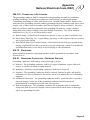
2 DIAGNOSTICS
A set of diagnostic functions allow you to test your system. These functions are in the
System Diagnostic Tests menu. You can perform these functions yourself to verify that
your system is in working order; or a Service Center Representative may ask you to perform
some of these functions.
3 NEW FEATURES
Occasionally the Service Center may send, via the satellite signal, a list of new features
available to you. The New Features option displays these and allows you to purchase them,
if desired.
4 PURCHASE INFO
This option displays a screen that shows your most recent pay per view purchases.
5 PREFERENCES
This option displays the User Preferences menu, which lets you do the following:
Select an alternate language. For example, if a program is transmitted in both English and
Spanish, you can choose which language you would prefer.
Note: This changes only the audio portion of programs and only if it is provided in multiple
languages. This does not change the menus displayed by the recorder.
Page 3-11
User and
Installation Guide
l Select Picture Size: You can choose the picture format if a program is transmitted in
both standard (4x3) and wide-screen (16x9) formats. You can use the 16x9 format only
if you have a wide-screen TV that supports the 16x9 format.
l Decide how to order the channel numbers while you are displaying the Program Guide.
You can display the channel numbers in ascending or descending order.
l Set up the system upgrade authorization. You can either have system upgrades loaded
automatically, or you can specify that you want to authorize each upgrade before it is
loaded.
l Set up your system to display caller identification: the name and telephone number of
the caller for your incoming telephone calls.
Note: Caller ID must be provided by your local telephone company.
Page 3-12
Getting Started
Local TV Link
3
L OCAL TV LINK
The Local TV Link feature allows you to view your local broadcast or cable channels via
your system. Once you get the channels set up, you can select and view those channels
through the Program Guide, or the Browse Banner; that is, the same way as you would
any of the satellite channels.
The quality of the audio and video you receive on local broadcast channels
depends on the distance and terrain (hilly or flat) between the broadcast station
and where you live, and the placement and quality of the broadcast TV antenna
you use. If you use cable channels, the audio and video quality of these
channels depends on your cable provider. If you have any questions about
these channels, please contact your service provider, not the Service Center!
Due to variations in quality among broadcast and cable television providers,
the recorder manufacturer cannot be held responsible for the quality of these
services
Note: The Program Guide automatically displays “prime time” program information for the
ABC, CBS, and NBC networks. “Prime time” hours vary in different areas. The information
may be inaccurate if regularly-scheduled programs are preempted or if other changes occur.
This section explains how you can add your local channels (whether they are network
channels or cable channels) yourself, assign the network affiliations, and then access them
via the Program Guide and via other channel selection methods.
YOUR BROADCAST TV ANTENNA
If you do not have a broadcast TV antenna installed, and wish to do so, there are a number
of options. You can receive a limited number of channels via a “rabbit ears” type antenna
that sits on your TV set, or a much wider range via a large VHF/UHF indoor/outdoor antenna. Of course, the higher the quality of the broadcast TV antenna you use, the greater its
range and the better your reception will be. Broadcast TV antennas are available from your
local consumer electronics retailers.
Make sure to follow the broadcast TV antenna installation instructions correctly. Make sure to
ground the broadcast TV antenna properly!! The antenna cable plugs into the VHF/UHF Ant.
In connection on the back panel of the recorder:
If your TV has an available Phono (RCA) Audio/Video input connections, connect them to
one of the recorder's Phono (RCA) Audio/Video outputs. This will provide stereo audio
and a higher quality picture than the picture obtained when using the recorder's RF Out (RF
or VHF Connection).
Once you have attached your broadcast TV antenna or cable hook-up to this connection, you
can set up your Local TV Link channels. The rest of this section explains how to do this.
Page 3-13
User and
Installation Guide
ADDING LOCAL OR CABLE CHANNELS
To add local broadcast or cable channels, do the following:
Remote
Buttons
1. Press the Mode button until the remote
is in SAT mode.
MODE
2. Press the Menu button to open the
Main Menu.
MENU
Menu Options
3. Select the System Setup option.
6
6
System Setup
4. Select the Installation option.
1
1
Installation
5. Select the Add Local Channel option. If
you are setting up your local channels for
the first time or switching options in the
Select Cable/Broadcast list, follow the
steps in order. Otherwise, go to step 8 to
add channels to the Selected Local
Channels list.
2
2 Add Local Chan.
6. Press the Left arrow button to move the
highlight into the Select Cable/
Broadcast list.
7. Press the Up or Down arrow button to
highlight either the Broadcast Channels
option or the appropriate Cable Channels
option (Standard, HRC, or IRC)(Contact
your cable TV provider for information on
whether you have a standard, HRC or IRC
cable system. Press the Select button to
choose the channel option.
T
H
E
M
E
Broadcast Channels
Standard Cable Channels
HRC Cable Channels
IRC Cable Channels
SELECT
Note: You can add either cable (Standard, HRC, or IRC) or broadcast channels,
not both. If you add one type of channel and then select another option, the Selected
Local Channels list will not change. In that case, the channels in the list would not
be correct for the option you selected. So, whenever you change the option, you
should also edit the Selected Local Channels list.
Page 3-14
Getting Started
Local TV Link
8. Select the Choose option. Press the Right
arrow and Up arrow button to highlight the
Choose and press the Select button. This will
display the Choose Local Channel screen.
3
Choose
9. Notice that the first time you display the
Choose Local Channel screen, the only
channel in the Selected Local Channels
list is channel 000. This is the AUX INPUT
channel, which is the input from the Auxiliary
Phono (RCA) Audio/Video Input, usually
attached to a VCR.
Channels
000
002
003
004
005
006
007
008
009
Press the Left arrow button to move the
highlight to the Channels list.
10.Select the desired channel in the
Channels list.
Either: Use the Up or Down arrow button
to highlight the desired channel number.
or
Use the number pad buttons to enter the
channel number.
Note: When entering a channel number
that has fewer than three digits (for
example, channel number 2 or 10), you
must enter zeros to make these channel
numbers three digits (for example, 002 or
010).
11.Press the Select button. This will display
the Edit Local Channel Name screen.
1
2
3
4
5
6
7
8
9
0
SELECT
12.Either: Use this screen to enter the local
call letters for the station, such as WXYZ,
DISC, KYXO etc.).
or
If you do not want to enter a name, select the
Save option and go to step 16.
Save
Page 3-15
User and
Installation Guide
13.Press the Left arrow button to move the
highlight to the keypad area.
T
H
E
M
E
14.Use the arrow buttons to highlight a
letter. Press Select. Repeat to spell
out the name of the channel. You can
enter up to five characters for the
channel name.
A
J
S
1
B
K
T
2
C
L
U
3
D
M
V
4
E
N
W
5
F
O
X
6
space
If necessary, select the space option to
insert a space in the channel name or the
<back option to correct a letter.
Note: You cannot use any channel name more
than once. If you try to do this, the recorder
will display an error message.
15.Select the Save option. This will display
the Select Network Affiliation screen.
16.Press the Left arrow button to move the
highlight into the Network Affiliation list.
Save
T
H
E
M
E
17.Use the Up and Down arrow buttons to
highlight the network affiliation
associated with the station you set up.
Chan: 002
ABC
CBS
NBC
None
18.Press Select.
SELECT
Page 3-16
G
P
Y
7
H
Q
Z
8
I
R
0
9
back
Getting Started
Local TV Link
19.Once you are finished, select the Save
option. The recorder will display the
Choose Local Channel screen. The
channel that you have just added should
now appear in the Selected Local
Channels list.
3
Save
20.Repeat steps 10 through 19 until all desired
channels are added.
Once you are finished, select the Save option
to save the list.
Save
DELETING A CHANNEL FROM THE SELECTED CHANNELS LIST
To delete a local broadcast or cable channel from the Selected Local Channels list so it no
longer appears in the Program Guide, do the following.
Note: You cannot delete Ch 000, since it is reserved for input via the Auxiliary Phono
(RCA) Audio/Video Input.
Remote
Buttons
1. Press the Mode button until the remote
is in SAT mode.
MODE
2. Press the Menu button to open the
Main Menu .
MENU
Menu Options
3. Select the System Setup option.
6
6
4. Select the Installation option.
1
1
5. Select the Add Local Channel option.
2
2 Add Local Chan.
6. Select the Choose option. This will display
the Choose Local Channel screen.
System Setup
Installation
Choose
Page 3-17
User and
Installation Guide
7. Press the Left arrow button twice to move
the highlight to the Selected Local
Channels list.
T
H
E
M
E
Either: Use the Up or Down arrow
button to highlight the channel you want
to delete.
Press Select. Repeat until all desired
channels are deleted.
SELECT
Note: When the Selected Local
Channels list is saved, the system will
arrange the list to fill in blank spaces
caused by deleting channels.
or
Select the Clear option to delete all channels
from the Selected Local Channels list.
Clear
Note: If you select the Clear option, the
recorder will display a warning message
indicating that you will be erasing the local
channels list completely. Select the Yes option
to erase the local channels list or select the No
option to keep the list.
8. Select the Save option to save the new list.
USING CH 000
IN THE
Save
CHANNELS LIST
Ch 000 in the Channels list appears as the default channel name AUXIN in the Selected
Local Channels list. Selecting Ch 000 in the Channels list lets you view the signal
coming into the Auxiliary Phono (RCA) Audio/Video Input. Usually this signal will be
from a connected VCR , DVD player, laserdisc player or other device, so that when you
change to channel 000, you are viewing the tape or disc being played by the connected unit.
Page 3-18
Getting Started
Local TV Link
3
EDITING THE NAME OF A CHANNEL
If you have entered the wrong channel name or want to add a channel name for a channel
(except Ch 000) that is on the Selected Local Channels list, do the following:
Remote
Buttons
Menu Options
1. Press the Mode button until the remote
is in SAT mode.
MODE
2. Press the Menu button to open the
Main Menu .
MENU
3. Select the System Setup option.
6
6
System Setup
4. Select the Installation option.
1
1
Installation
5. Select the Add Local Channel option.
2
2 Add Local Chan.
6. Select the Choose option. This will display
the Choose Local Channel screen.
Choose
7. Select the desired channel in the
Channels list.
Either: Press the Up or Down arrow
button to move the highlight to the desired
channel number in the Channels list.
or
On the remote control number pad,
press the desired channel number. This
will move the highlight to that channel
number.
8. Press the Select button. This will display
the Edit Local Channel Name screen.
Use this screen to enter the new channel
name.
1
2
3
4
5
6
7
8
9
0
SELECT
Page 3-19
User and
Installation Guide
9. Press the Left arrow button to move the
highlight to the keypad area.
10.Use the arrow buttons to highlight
a letter. Press Select. Repeat to spell
out the name of the channel.
T
H
E
M
E
A
J
S
1
B
K
T
2
C
L
U
3
D
M
V
4
E
N
W
5
F
O
X
6
space
If necessary, select the space option
to insert a space in the channel name
or the <back option to correct a letter.
Note: You cannot duplicate the name
of a channel. If you use any channel
name more than once, the recorder will
display an error message.
11.Select the Save option. The recorder will
display the Select Network Affiliation
screen.
Save
If desired, you can change the network
affiliation at this time. See step 16 in
Adding Local or Cable Channels on page
3-14.
12.Select the Save option. The recorder will
return to the Choose Local Channel screen.
The new channel name will appear in the
Selected Local Channels list.
13.Select the Save option to save the new
channel name.
Page 3-20
Save
Save
G
P
Y
7
H
Q
Z
8
I
R
0
9
back
4
Using the System
ABOUT THE PROGRAM BANNER
The Program Banner is displayed for a few seconds at the top and bottom of the TV screen
every time you change the channel, begin playback of a recording, or press the View button
on the remote. The top Program Banner provides information about the program that you
are viewing. The bottom Program Banner provides information about the status of your
VCR. The figures below show the Program Banners for your satellite channels and your
local broadcast or cable channels. The information varies, depending on the specific program, but may include any or all of the items in the following figures:
PROGRAM BANNER FOR SATELLITE CHANNELS:
Current Date
Current
Time
Current Program Title
Tue 10/11
10:13 am
Raging Bull
Time Left: 1:02
PG-13[V,L]
Remaining Time of
Program
Rating & Content
Codes
Channel Number
300
HBO-E
List:MOM
Channel
Name
Active Favorites
List (color-coded)
PROGRAM BANNER FOR LOCAL BROADCAST TV OR CABLE TV CHANNELS:
Current Date
Current
Time
Tue 10/11
10:13 am
Channel Number
Local Programming
9
UPN
List:ALL CHAN
Channel
Name
Active Favorites List
Page 4-1
User and
Installation Guide
While recording a program, the Program Banner information is expanded to include more
information, including a graphical tape position indicator.
At the start of playback, the Program Banner provides information about the program
being currently played, as well as the current playback status. Depending on the recorded
program, the following information may be displayed.
PROGRAM BANNER DURING RECORDING AND PLAYBACK:
1
2
Thu 12/25
12:00 am
503
101 Dalmatians
Time Left: 0:36
G
PPV4
List:ALL CHAN
7
3
8
9
16
15
0:12:34
Index:01
Tape in
Play
D-VHS
Hi-Fi
AC3
10
11
12
13
Memory
1. Current Date/Time
2. Remaining Time of Program
Displayed when a satellite channel is
received.
3. Current Program Title
4. Current Channel Number
5. Current Channel Name
6. Active Favorites List (color-coded)
7. Rating & Content Codes
8. Counter Reading
9. Counter Memory On/Off
Position
14
10. Operation Mode
When the operation mode is changed, the
new mode is displayed – RECORD
(5 sec.), PLAY (5 sec.), FF/REW (5 sec.
when engaged from stop mode), RECORD
PAUSE (for as long as Pause is engaged),
and RECORD TIMER *:* * (5 sec.).
11. Recording Mode
12. Audio Mode Indicators
13. AC3 Indication
14. Tape Position Indicator
15. Tape in indicator
When a cassette is loaded, the message is
displayed for 5 seconds.
16 Index Indication
Page 4-2
4
5
6
Using the System
About the Browse Banner
4
ABOUT THE BROWSE BANNER
You can use the Browse Banner to change channels; see what other programs are on
without removing the current program from view; and, create an event timer.
The Browse Banner information is displayed at the top and bottom of your TV screen and
includes the items in the following pictures:
BROWSE BANNER FOR SATELLITE CHANNELS:
Current Date
Current
Time
Tue 10/11
10:13 am
Current Program Title
Current Channel Number
300
Raging Bull
HBO-E
Current
Channel
Name
New
Program
Time
New
Channel
Number
New
Channel
Name
New Program
Date/Time
322
MAX-W
List:MOM
Active Favorites List
(color-coded)
Tue10/11
10:00 am
Pulp Fiction
NC-17[V,LN,SC]
Time
Remaining
Time Left:1:47
Rating and Content Codes
BROWSE BANNER FOR LOCAL BROADCAST TV OR CABLE TV CHANNELS:
Current Date
Current
Time
New
Channel
Number
New
Channel
Name
Tue 10/11
10:13 am
20
WGPR
Current Program Title
Local Programming
Local Programming
Current Channel Number
9
KNBC
Tue10/11
10:00 am
Current
Channel
Name
New Program
Date/Time
List:MOM
Active Favorites List
Page 4-3
User and
Installation Guide
OPENING THE BROWSE BANNER
To open the Browse Banner while you are viewing a program, press the Right arrow
button.
B
R
O
W
S
E
VIEWING BANNER INFORMATION FOR OTHER CHANNELS
To view Browse Banner information about other channels, do the following:
Remote
Buttons
1. Press the Mode button until the remote is in
SAT mode.
MODE
2. Press the Right arrow button to display the
Browse Banner for the current program.
3. Either: Enter the desired 3-digit channel
number using the number pad buttons.
Menu Options
B
R
O
W
S
E
1
2
3
4
5
6
7
8
9
Note: When changing channels to a
channel number that has fewer than three
digits (for example, channel number
2 or 10), you must enter zeros to make
these channel numbers three digits
(for example, 002 or 010).
0
or
Press the Up or Down arrow button to
display the desired channel in the
bottom part of the Browse Banner.
The Browse Banner displays only the
channels in the active Favorites List.
4. You can press the Info button for more
information about the program listed in the
Browse Banner.
Page 4-4
IN
FO
Using the System
About the Browse Banner
4
CHANGING CHANNELS VIA THE BROWSE BANNER
If you are browsing and see a program that you would like to view, do the following to
change to the new channel:
Remote
Buttons
Menu Options
1. Make sure the channel you want to view is
displayed in the lower portion of the
Browse Banner.
2. Press the Select button to change to the new
channel. The Browse Banner automatically
closes.
SELECT
CLOSING THE BROWSE BANNER
To close the Browse Banner, do the following:
L
Press the Cancel button. Your recorder remains tuned to the channel you are viewing.
Or you can wait a few minutes, and the Browse Banner automatically closes.
CA
NC
E
Page 4-5
User and
Installation Guide
ABOUT
THE
PROGRAM GUIDE
The Program Guide provides a complete listing of the available channels and programs.
Note: You must add your local broadcast or cable channels to the Program Guide yourself.
See Local TV Link on page 3-13. However, the Program Guide automatically displays
"prime time" program information for the major broadcast networks. "Prime time" hours
vary in different areas. The information may be inaccurate if regularly-scheduled programs
are preempted, or if other changes occur.
You can use the Program Guide to change channels; see what programs are scheduled in
the future; purchase pay per view programs; and, create an event timer.
In the Program Guide, you may see some channel numbers with a red background — these
are channels to which you have not subscribed. See Available Services on page 1–5 for
more information about subscription channels and adding channels.
The Program Guide may contain any or all of the items shown below:
Current
Date and Time
LocksStatus
of System
Tue - 3/23
8:30 pm
Currently Active
Favorites List (color-coded)
TM
Favorite List
ALL CHAN
Day of the
Programs in View
Auxiliary Input
000
AUXIN
Auxiliary Input
Local TV Link
009
KUSA
Local Programming
Tue
3/23
8:30 pm
142
ESPN2
NBA PreGame
Update
160
MTV
Ren & Stimpy
9:00 pm
142
9:30 pm
Channel Number
of Number of
Hours to Skip
Time of the
Programs in View
NBA Playoffs
Are You Afraid?
172
DISN
Last of the Mohicans
320
MAX-E
The Lives of a Bengal Lancer
To Be
Announced
Program List
Bounty Tracker
Best of Comic
Relief
Channel Number and Name
Favorite List
Each Favorites List name is shown in a different color.
Indicates that this program began or will end in a time period that is
not in view.
Indicates that the current time period available is in view (you cannot
display a time earlier than this).
Page 4-6
Using the System
About the Program Guide
4
Indicates that the last viewable time period is in view (you cannot
display a time later than this).
142
This display is normally blank with two arrows. When it is not blank, it
shows:
The number of hours being entered on the remote control number pad.
Press the Left or Right arrow button to skip the display forward or
backward that number of hours.
or
The channel number of the channel being entered on the remote
control number pad. To skip to the program listing for a channel,
enter the channel number and press the Select button.
Note: The Program Guide can display programs scheduled for a
limited time beyond the present.
OPENING THE PROGRAM GUIDE
To open the Program Guide and view a listing of available channels and programs, do the
following:
Remote
Buttons
1. Press the Mode button until the remote is in
SAT mode.
2. Either: Press the Guide button.
Menu Options
MODE
GU
ID
E
or
Press the Menu button to open the
Main Menu. Then, select the Program
Guide option.
MENU
1
Program Guide
1
Page 4-7
User and
Installation Guide
SCANNING THROUGH CHANNELS
You can scan through the available channels in the Program Guide to see what programming is available. To do this, do the following:
Remote
Buttons
Either: Enter the desired 3-digit channel
number. Optional: Press the Select button.
Menu Options
1
2
3
4
5
6
7
8
9
or
0
Press the Up or Down arrow button to
highlight the desired channel.
or
Press the Fast Forward button to page up,
or the Rewind button to page down through
the Program Guide.
If desired, press the Info button for more
information about the highlighted program.
Press the Select button to change to the new
program.
Note: Only the channels on the active
Favorites List are displayed.
Page 4-8
IN
FO
SELECT
Using the System
About the Program Guide
4
CHANGING CHANNELS VIA THE PROGRAM GUIDE
To change to a new channel using the Program Guide, do the following:
Remote
Buttons
1. Press the Mode button until the remote is in
SAT mode.
MODE
GU
ID
E
2. Press the Guide button to open the Program
Guide.
3. Either: Enter the desired 3-digit channel
number using the number pad buttons.
Then, press Select to change to the new
program.
Note: When changing channels to a
channel number that has fewer than three
digits (for example, channel number
2 or 10), you must enter zeros to make
these channel numbers three digits
(for example, 002 or 010).
Menu Options
1
2
3
4
5
6
7
8
9
0
SELECT
or
Press the Up or Down arrow button to
highlight the desired channel. Then, press
Select to change to the new program.
Note: Only the channels in the active
Favorites List are displayed.
SELECT
If you select a program that has not started yet, the recorder displays the
Create an Event Timer menu. See Viewing Information About Programs
on page 4-10 and Event Timers on page 5-22 for more information.
Page 4-9
User and
Installation Guide
VIEWING INFORMATION ABOUT PROGRAMS
If you want more information about a program listed in the Program Guide, do the following:
Remote
Buttons
1. Press the Mode button until the remote is in
SAT mode.
2. Press the Guide button to open the Program
Guide.
Menu Options
MODE
GU
ID
E
3. Highlight the desired program using the
arrow buttons on the remote control.
4. Press the Info button. This displays the
information screen, which shows start and
end times, channel, and other information
about the program.
IN
FO
L
5. Press the Cancel button to return to the
Program Guide.
CA
NC
E
CLOSING THE PROGRAM GUIDE
To close the Program Guide, do the following:
L
Press the Cancel button. The recorder returns to the channel you were viewing before you
opened the Program Guide.
CA
Page 4-10
NC
E
Using the System
About Themes
4
ABOUT THEMES
The system allows you to list and select programs according to the theme of their contents.
For example, you can list just movies or just sports. You can then quickly list programs
based on that theme, and select the program you want without having to search through all
the channels. The themes list only displays programs that are available for the current date.
DISPLAYING PROGRAMS BY THEME
Remote
Buttons
1. Either: While viewing a program, press the
Left arrow button.
or
Press the Menu button to open the Main
Menu . Then, select the Themes option.
Menu Options
T
H
E
M
E
MENU
2
2
Themes
1
Movies
2. The recorder displays the Theme Categories
menu, which lists the available themes.
3. Select the theme you want. This displays the
list of events with that theme. For example, if
you select the Movies theme, you will see a list
of upcoming movies, as shown here. Programs
on channels to which you have not subscribed
are shown with a red background.
Sat 3/22
6:48 pm
Movies
Available Events
LIFE
3/22 7:00p
The Return of the Brady...
HBO
3/22 8:50p
City Slickers
HBO2 3/22 8:55p
Cancel
Animal House
SHOW 3/22 9:00p
The Unbearable Lightness...
TMC
3/22 9:00p
Bullets Over Broadway
AMC
3/22 10:00p Dr. Cyclops
Page
Up
CMAX 3/22 10:30p Clear And Present Danger
TNT
3/22 10:30p Return of the Jedi
TBS
3/22 11:00p Back to the Future
Page
Down
Page 4-11
User and
Installation Guide
SELECTING A PROGRAM IN THE THEMES L IST
You can change to a program in the Themes list by doing the following:
Remote
Buttons
1. Press the Mode button until the remote is in
SAT mode.
Menu Options
MODE
2. Use the Page Up and Page Down options
(or the Fast Forward and Rewind buttons)
to speed your search for the desired program.
Page
Up
Page
Down
3. Press the Left arrow button to move the
highlight to the program list.
T
H
E
M
E
4. Press the Up or Down arrow button to
highlight the desired program.
5. Press the Select button to view the program
or press Cancel to close the Themes list
without selecting a program.
Page 4-12
SELECT
Using the System
Ordering Pay Per View Programs
4
ORDERING PAY PER VIEW PROGRAMS
A pay per view program is a program that you order and pay a small fee to view once.
There are many types of programs available through the pay per view service, such as
movies, sports, comedies, and musicals. You can find out what pay per view programs are
available by viewing the Program Guide information starting at channel 500 (see About
the Program Guide on page 4-6). To preview upcoming pay per view programs, view the
Preview Channel. See Available Services on page 1-5 for more information about pay per
view programs. To purchase and view a pay per view program, do the following:
Your recorder must be connected to an active telephone line at all times, in
order to purchase pay per view programs using the recorder.
Remote
Buttons
Menu Options
1. Select the desired pay per view program
using the Program Guide.
2. If the system is locked, enter the system
password using the number pad buttons.
1
2
3
4
5
6
7
8
9
*
*
*
*
OK
Select the OK option to accept the
password.
3. Either: Purchase the pay per view event
by selecting the Yes option. The recorder
0
Yes
displays a confirmation screen.
(see step 4).
or
If you do not want to purchase the pay per
view program, press the Up or Down
arrow button (if you are viewing a
program) or select the No option or the
Cancel option. If you do this, you can
No
Cancel
stop here.
Page 4-13
User and
Installation Guide
4. At the Confirmation Screen:
Either: Select the Yes option again to confirm
Yes
the purchase. The fee will appear on your
invoice.
or
Select the No option or the Cancel option to
cancel the purchase.
Note: You cannot cancel previously ordered
pay per view programs using this procedure.
No
Cancel
To order through the Service Center:
Call the Service Center to order the pay per view program. The pay per view fee is
added to your next invoice. This method may add an additional service fee to the pay
per view fee.
LOCKING PAY PER VIEW PROGRAMS
You can lock your system so that only users who know the password can order pay per
view programs. See Locking the System on page 4-25 for details.
FAVORITES LISTS
ABOUT FAVORITES LISTS
Favorites Lists are lists of your favorite channels that you create and change (adding or
deleting channels) as you wish. When you make a Favorites List active, the recorder
displays only the channels in that list.
l You can still view a channel not on the list by entering the 3-digit channel number using
the remote number pad buttons, or by selecting a program on that channel using the
Theme Categories menu.
l There is also a Favorites List called "ALL CHAN," which contains all the channels.
You cannot make any changes to this list. If you want all channels in view, make sure
that the "ALL CHAN" Favorites List is active.
You can define up to four different Favorites Lists, each with a maximum of 30 channels.
Each Favorites List is indicated by a unique color in the Program Banner, the Browse
Banner, and the Program Guide.
When you receive your system, these four lists are named "LIST 1," "LIST 2," "LIST 3,"
and "LIST 4." They are empty until you add channels to them.
Page 4-14
Using the System
Favorites Lists
4
CREATING OR MODIFYING A FAVORITES LIST
You can add channels to, and remove channels from a Favorites List.
Remote
Buttons
1. Press the Mode button until the remote is in
SAT mode.
MODE
2. Press the Menu button to open the
Main Menu .
MENU
3. Select the Favorites option.
4
Menu Options
4
4. Select the Favorites List to be changed. This
example shows the list names that come with
your system. Note that you cannot modify the
"ALL CHAN" list in any way.
Favorites
Selected List
ALL CHAN
LIST 1
LIST 2
LIST 3
LIST 4
5. Select the Modify List option. This displays
the channels in the Favorites List.
Modify List
LIST 2
FOX
CBS
HBO
DISC
SHO - E
MAX2
MTV
FOX
AMC
ABC
NBC
6. At any time you can select the Clear option to
immediately remove all channels from the
current list.
Clear
Page 4-15
User and
Installation Guide
7. In the Channels list, highlight the
channel you want to add to your Favorites
List.
Channels
CNN - 200
DISC - 182
FAM - 180
Either: Use the Up or Down arrow button
TLC - 178
to bring the desired channel into view.
TOON - 176
DISNE - 172
NICK - 170
or
TNN - 168
Use the number pad buttons to enter the
channel number.
CMT - 162
1
2
3
4
5
6
7
8
9
Note: When entering a channel number
that has fewer than three digits (for
example, channel number 2 or 10), you
must enter zeros to make these channel
numbers three digits (for example,
002 or 010).
0
SELECT
Press the Select button.
8. Repeat step 7 until all desired channels are
added.
9. To delete a channel from your Favorites List,
highlight the channel in the Favorites List .
LIST 2
SELECT
FOX
CBS
HBO
Press the Select button.
DISC
SHO - E
MAX2
MTV
FOX
AMC
ABC
10.Repeat step 9 until all desired channels are
deleted.
11.Select the Save option to save all changes
to the Favorites List or press Cancel to discard
the changes.
Page 4-16
NBC
Save
Using the System
Favorites Lists
4
CHANGING THE NAME OF A FAVORITES LIST
Since the lists are initially named "LIST 1," LIST 2," etc., you may want to give them more
meaningful names. "MOM," "DAD," or "MYFAV" are all possible Favorites Lists names.
Remote
Buttons
1. Press the Mode button until the remote is in
SAT mode.
MODE
2. Press the Menu button to open the
Main Menu .
MENU
3. Select the Favorites option.
4. Select the Favorites List to be changed.
4
Menu Options
4
Favorites
Selected List
ALL CHAN
LIST 1
LIST 2
LIST 3
LIST 4
5. Select the Edit List Name option.
6. At any time, you can select the Clear option
to immediately remove all characters from
the name.
Edit List Name
Clear
7. Use the arrow buttons to highlight a letter.
Press Select. Repeat to spell out the
desired name.
If necessary, select the space option to
insert a space in the channel name or the
< back option to correct a letter. You can
enter up to eight characters, including
spaces.
8. Select the Save option to save all changes.
Save
Page 4-17
User and
Installation Guide
MAKING A FAVORITES LIST ACTIVE
When a Favorites List is active, the recorder displays only the channels in that
list. However, you can still view a channel not on the list by entering the 3digit channel number using the remote number pad buttons, or by selecting
a program on that channel using the Theme Categories menu.
Note: When changing channels to a channel number that has fewer than three
digits (for example, channel number 2 or 10), you must enter zeros to make
these channel numbers three digits (002 or 010).
Remote
Buttons
1. Press the Mode button until the remote is in
SAT mode.
2. Either: If the Program Guide is open, press
the Guide button to select the next Favorites
List. Press Guide repeatedly to scan through
all available lists.
Menu Options
MODE
GU
ID
E
or
Press the Menu button to open the
Main Menu.
3. Select the Favorites option.
4. Highlight the desired Favorites List
(example lists are shown here).
MENU
4
4
Favorites
Selected List
ALL CHAN
DAD
MOM
SIS
LIL BRO
5. Select the Save option to make the highlighted
Favorites List active.
Note: If you try to make an empty Favorites
List active, the recorder highlights the Modify
List option. You must add at least one channel
to this Favorites List before you select it.
Page 4-18
Save
Using the System
Security Features
4
SECURITY FEATURES
ABOUT SECURITY FEATURES
Security features let you make sure your system is being used the way you want it to be
used.
You can use two levels of security:
l You can lock your system, so that only those who know the password can access locked
features (see below).
l You can set up a Personal Identification Number (PIN) at the Service Center to keep
unauthorized users from calling and ordering services (see Service Center Security on
page 4-29).
PARENTAL AND SYSTEM LOCKS
You can set system locks to keep anyone who does not know the password from:
l Viewing one or more specified channels.
l Viewing programs with certain rating or extended rating (content) codes.
l Purchasing additional cost services such as pay per view programs.
l Using the recorder front panel buttons.
To set locks, you must do the following:
1. Create the channel or program locks (you do not need to do this if you wish to lock only pay
per view services).
2. Lock the recorder front panel buttons, if you wish.
3. Lock the system. This puts the locks you have created into effect, and also automatically
locks the purchase of additional cost services.
Once the system is locked, anyone who wants to access the locked services must enter the
password.
First you set the locks; then you lock the system.
You must lock your system in order to put all locks into effect.
If you want to lock only pay per view services, you do not need to create any
special locks. Just lock the system, and this automatically locks pay per
view services.
Page 4-19
User and
Installation Guide
To lock the system, you must set a password:
l When you lock the system, you must enter and verify a 4-digit number password, which
you make up.
l Later, you must enter the same password to unlock the system, make changes to locked
features, or access locked programs.
When you have locked the system:
l If you try to access a locked program or channel, the recorder displays a message
prompting you to enter the password. You must also enter the password to access the
Parental and System Locks menu.
n The system allows you three tries to enter the correct password.
n If you do not enter the correct password in three tries, the system does not allow
more tries for several minutes.
l If you enter the correct password, you can then access the locked item or the Parental
and System Locks menu.
l If you exit a locked item or the locks menu, you must reenter the password to access the
item or menu again.
If you forget your password, you will need to speak with a Service Center
Representative. You may need to provide the following information: (1) your
name; (2) your address; (3) your telephone number; (4) your recorder serial
identification number; and, (5) your Personal Identification Number (PIN), if
used.
CREATING OR MODIFYING C HANNEL LOCKS
Remote
Buttons
1. Press the Mode button until the remote is in
SAT mode.
MODE
2. Press the Menu button to open the
Main Menu.
MENU
3. Select the Locks option.
Page 4-20
5
Menu Options
5
Locks
Using the System
Security Features
4. If the system is locked, enter the
system password using the number pad
buttons. As soon as you enter the fourth
digit of the password, the system
highlights the OK option.
Press the Select button.
1
2
3
4
5
6
7
8
9
*
*
*
0
5. Select the Channel Locks option.
2
6. Press the Left arrow button to move the
highlight into the Channels list. Highlight
each channel that you want to lock or
unlock. If necessary, press the Up or Down
arrow button to bring the desired channels
into view.
You can also enter each channel number
directly using the number pad buttons.
*
4
2
Channel Locks
T
H
E
M
E
1
2
3
4
5
6
7
8
9
0
Press the Select button to lock or unlock the
channel. If the checkbox next to the channel
shows a checkmark in it, it is locked. If there
is no checkmark, the channel is not locked.
SELECT
HBO-E - 300
This is an unlocked channel
FOX - 247
This is an locked channel
7. Press the Right arrow button to move the
highlight to the options. Select the Save
option to save the changes.
B
R
O
W
S
E
Save
8. If the system is not already locked, lock it to
put the lock you just created into effect. See
Locking the System on page 4-25.
Page 4-21
User and
Installation Guide
CREATING OR MODIFYING PROGRAM LOCKS
Do the following to lock programs with certain rating or extended rating (content) codes.
Only someone who knows the password can then view these programs. See Glossary on
page A-7 for a definition of each of the rating codes.
Parents beware, the rating and extended rating (content) codes that the system
uses for program locks reflect the codes that the original program providers
assigned to the programs. The actual content of the programs may differ from
their assigned ratings.
Remote
Buttons
1. Press the Mode button until the remote is in
SAT mode.
MODE
2. Press the Menu button to open the
Main Menu.
MENU
3. Select the Locks option.
4. If the system is locked, enter the system
password using the number pad buttons.
As soon as you enter the fourth digit of
the password, the system highlights the
OK option. Press the Select button.
Menu Options
5
5
1
2
3
4
5
6
7
8
9
Locks
*
*
*
*
0
5. Select the Ratings Locks option.
1
6. Highlight the rating that corresponds to the
lowest desired audience age.
1
Ratings Locks
Rating
PG
Note: All ratings that apply to audience age
PG-13
ranges above that of the selected rating are
also selected.
R
NC-17
NR / AO
For example, if you lock PG-13 rated
programs, then all programs with the R,
NC-17, and NR/AO rating are also locked.
Press the Select button.
Page 4-22
SELECT
Using the System
Security Features
7. Highlight the expanded rating code(s) to
lock, if desired.
4
Expanded Rating
Violence
Language
Press the Select button.
Nudity
SELECT
Sexual Content
8. To unlock a rating code, highlight the
code and then press the Select button.
SELECT
9. Select the Save option to save the changes.
Save
10.If the system is not locked, lock it to put the
lock you just created into effect. See Locking
the System on page 4-25.
LOCKING THE RECORDER FRONT PANEL BUTTONS
Do this procedure to set up the system to ignore all recorder front panel buttons except the
Power button. This is useful if you want to prevent anyone else from changing the channel
or selecting other programs. This does not lock the remote control buttons, so you should
keep or hide the remote.
Remote
Buttons
1. Press the Mode button until the remote is in
SAT mode.
MODE
2. Press the Menu button to open the
Main Menu .
MENU
3. Select the Locks option.
4. If the system is locked, enter the system
password using the number pad buttons.
As soon as you enter the fourth digit of the
password, the system highlights the
OK option.
Press the Select button.
Menu Options
5
5
1
2
3
4
5
6
7
8
9
Locks
*
*
*
*
0
Page 4-23
User and
Installation Guide
5. In the Parental and System Locks menu,
select the Front Panel Lock option.
4
4 Front Panel Lock
6. At the Lock Front Panel Buttons screen,
select the Lock option.
Lock Front Panel Buttons
Disable the operation of the front panel buttons.
The system must be locked for this lock to take
effect!
Do you wish to lock the front panel buttons?
7. If the system is not locked, lock it to put
the lock you just created into effect. See
Locking the System on page 4-25.
Yes
Cancel
No
UNLOCKING THE RECORDER BUTTONS
Note: You must use the remote control to unlock the recorder front panel buttons.
Remote
Buttons
1. Press the Mode button until the remote is in
SAT mode.
MODE
2. Press the Menu button to open the Main Menu.
MENU
3. Select the Locks option.
4. If the system is locked, enter the system
password using the number pad buttons.
As soon as you enter the fourth digit of
the password, the system highlights the
OK option.
Press the Select button.
5. Select the Front Panel Lock option.
6. Select the Yes option.
Menu Options
5
5
1
2
3
4
5
6
7
8
9
Locks
*
*
*
*
0
4
4 Front Panel Lock
Yes
ACCESSING A LOCKED ITEM
Do the following to view a locked channel or program when the system is locked. See
Ordering Pay Per View Programs on page 4-13 for the procedure to order a pay per view
program when the system is locked.
Page 4-24
Using the System
Security Features
Remote
Buttons
4
Menu Options
1. Choose a channel or a program that you have
locked. The recorder displays an ATTENTION
message telling you that the item is locked and
prompting you to enter the system password.
2. If the system is locked, enter the system
password using the number pad buttons.
As soon as you enter the fourth digit of
the password, the system highlights the
OK option. Press the Select button.
1
2
3
4
5
6
7
8
9
*
*
*
*
0
3. Select the OK option.
OK
LOCKING THE SYSTEM
Lock your system to put any channel, program rating, and front panel button locks you have
created into effect.
Locking your system will automatically lock the purchase of additional cost
services, such as pay per view programs.
If you forget your password, you will need to speak with a Service Center
Representative. You may need to provide the following information:
(1) your name; (2) your address; (3) your telephone number; (4) your
recorder serial identification number; and, (5) your Personal Identification
Number (PIN), if used.
Remote
Buttons
1. Press the Mode button until the remote is in
SAT mode.
MODE
2. Press the Menu button to open the
Main Menu .
MENU
Menu Options
Page 4-25
User and
Installation Guide
3. Select the Locks option. If the system
prompts you for a password, it has already
been locked.
5
5
Locks
4. Select the Lock System option.
The recorder displays a message prompting
you to enter the system password.
Note: If this option says "Unlock System"
instead, then the system has already been
locked.
3
3
Lock System
5. Enter and verify a password, using the
number pad buttons. Write down the
password and put it in a safe place.
From this time on, you must enter this
password to unlock the system.
1
2
3
4
5
6
7
8
9
*
*
*
*
0
6. Select the OK option. All the locks you
have created are now in effect.
OK
UNLOCKING THE SYSTEM
After you do this procedure, all locks are turned off until you lock the system
again.
Remote
Buttons
1. Press the Mode button until the remote is in
SAT mode.
MODE
2. Press the Menu button to open the
Main Menu.
MENU
3. Select the Locks option.
Page 4-26
5
Menu Options
5
Locks
Using the System
Security Features
4. Enter the system password using the
number pad buttons. As soon as you
enter the fourth digit of the password,
the system highlights the OK option.
Press the Select button.
1
2
3
4
5
6
7
8
9
*
*
4
*
*
0
5. Select the Unlock System option.
Note: If this option says "Lock System"
instead, then the system has already been
locked.
3
3
Unlock System
CHANGING THE SYSTEM P ASSWORD
Remote
Buttons
1. Press the Mode button until the remote is in
SAT mode.
MODE
2. Press the Menu button to open the
Main Menu .
MENU
3. Select the Locks option.
4. If the system is locked, enter the system
password using the number pad buttons.
As soon as you enter the fourth digit of
the password, the system highlights the
OK option. Press the Select button.
Menu Options
5
5
1
2
3
4
5
6
7
8
9
Locks
*
*
*
*
0
5. Select the Change Password option.
6. Enter the current password using the
number pad buttons. As soon as you
enter the fourth digit of the password,
the system highlights the OK option.
Press the Select button.
5
5 Change Password
1
2
3
4
5
6
7
8
9
*
*
*
*
0
Page 4-27
User and
Installation Guide
7. Enter the new password using the number
pad buttons. As soon as you enter the
fourth digit of the password, the system
highlights the OK option. Go on to the
next step.
1
2
3
4
5
6
7
8
9
*
*
*
*
0
8. Either: Select the OK option.
OK
or
If you do not want to change the password,
select the Cancel option to cancel the
password change. You can stop here.
9. Enter the new password again for
verification, using the number pad
buttons. As soon as you enter the fourth
digit of the password, the system
highlights the OK option. Press the
Select button.
Note: Write down the new password and
keep it in a safe place.
L
Cancel
CA
N
CE
1
2
3
4
5
6
7
8
9
*
*
*
*
0
DISCARDING ALL SETUP INFORMATION
If you want to discard changes using the system menus and reset the recorder to be the
same as when it was shipped from the factory, do the following:
When you reset the recorder to default settings, all event timers and settings
that enable the recorder to control a VCR will be discarded.
If you have defined security locks on the recorder, and the recorder is locked,
these locks will not be discarded. If the recorder is unlocked, these locks will
be discarded. (You can confirm whether locks have been discarded by opening
the Program Guide and seeing if the lock symbol is displayed.)
The system password is not discarded. You cannot reset the recorder to default
settings to discard a password you have forgotten, nor can an unauthorized
person do so to bypass a security lock.
Page 4-28
Using the System
Security Features
Remote
Buttons
1. Press the Mode button until the remote is in
SAT mode.
MODE
2. Press the Menu button to open the
Main Menu .
MENU
4
Menu Options
3. Select the System Setup option.
6
6
System Setup
4. Select the Installation option.
1
1
Installation
5. Select the Factory Defaults option.
5
5 Factory Defaults
6. Select the Yes option.
Yes
SERVICE CENTER SECURITY
You can set up a Personal Identification Number (PIN) at the Dish Service Center for call-in
requests only. Anyone calling the Service Center with a request must provide this PIN
to authorize any transactions to your account, whether speaking with a Service Center
Representative or using the Service Center automatic telephone assistance system. This
includes purchasing services, making account inquiries, and overriding the system
password.
When you call the Service Center to authorize your service, you can set up a PIN. You
may call the Service Center at any later time to set up a PIN.
If you forget your PIN, you will need to speak with a Dish Service Center
Representative. The Service Center Representative may ask for additional
information to confirm that you are authorized to make transactions to your
account.
Page 4-29
User and
Installation Guide
ELECTRONIC MAIL
You may occasionally receive electronic mail from the Service Center via the satellite
signal. If your recorder is powered on and the LED is blinking on the front panel, you
have mail. This mail typically tells you about upcoming events, programs, special offers,
and system changes. You may also receive mail that is specifically addressed to you, telling
you about billing changes or asking you to call the Service Center.
Note: You cannot send mail, only receive it.
When you have unread messages, the following occurs.
l When you press the Info button for information on a program, the Info menu displays
an envelope.
l The Power light on the recorder front panel flashes.
It is important that you read, and then delete the mail messages that you
receive. The recorder memory can store only a limited number of messages.
If it receives more messages than it can hold, it deletes the oldest messages, as
necessary, to make room. If this happens, you may miss important
information.
READING YOUR MAIL
Remote
Buttons
1. Press the Mode button until the remote is in
SAT mode.
MODE
2. Press the Menu button to open the
Main Menu.
MENU
3. Select the Mail option.
4. Use the arrow buttons to move the
highlight to the mail message.
Press Select.
3
Menu Options
3
Mail
Select Mail to Read
SELECT
4/21 New From
The Disney...
4/12 Upgrade
your program...
3/25 Pay-PerView Event...
2/10 New
Channel Added...
Page 4-30
Using the System
Software Upgrades
4
5. If necessary, press the Up or Down arrow
button to view all of the message.
6. Either: After you are finished reading,
select the Delete option to delete the mail
message.
Delete
Save
or
Select the Save option to save the message.
SOFTWARE UPGRADES
Occasionally, the Service Center may send you, at no extra cost, a list of newly available
system features. These features will be sent to you using the "flash" feature, which allows
you to get system upgrades via satellite. You can set up your system to automatically install
these system upgrades, or you can have the system notify you before installing them.
To set up your system to either notify you about new upgrades, or to automatically install
new upgrades, do the following:
Remote
Buttons
1. Press the Mode button until the remote is in
SAT mode.
MODE
2. Press the Menu button to open the
Main Menu .
MENU
Menu Options
3. Select the System Setup option.
6
6
System Setup
4. Select the Preferences option.
5
5
Preferences
5. Select the System Upgrades option.
4
4 System Upgrades
Page 4-31
User and
Installation Guide
6. Press the Left arrow button to move the
highlight to the Without my permission
option.
7. Press the Up or Down arrow button to
select either the Without my permission
option to have upgrades automatically
downloaded to your system or the Ask
before downloading option to have
upgrades downloaded with your
authorization first. If you select the Ask
before downloading option, the recorder
will display a message to notify you when
an upgrade is available.
T
H
E
M
E
Without my permission
Ask before downloading
Note: With either option, the download will
occur only when the recorder is off.
8. Select the Save option.
Page 4-32
Save
Using the System
Viewing Programs in Other Languages
4
VIEWING PROGRAMS IN OTHER LANGUAGES
You can change the language of the programs you view by using the Alternate Audio menu.
To change to an alternate language, do the following:
Note: An alternate language may not be available for all programs. Some programs, such
as movies, indicate at the start of the program whether an alternate language is available.
Also, the alternate language applies only to the audio portion of programs and does not
change the menus displayed by the recorder.
Remote
Buttons
1. Press the Mode button until the remote is in
SAT mode.
Menu Options
MODE
2. Press the Menu button to open the Main Menu. MENU
3. Select the System Setup option.
6
6
System Setup
4. Select the Preferences option.
5
5
Preferences
5. Select the Alternate Audio option.
1
1
6. Press the Left arrow button to move the
highlight to the list of languages.
T
H
E
M
E
7. Use the Up or Down arrow button to
highlight the desired language and
press Select.
Languages
English
Spanish
French
Note: If the program is being transmitted
in a language not listed, then the Alternate
option selects that language.
If not, then the Alternate option selects
English.
Alternate Audio
German
Italian
Japanese
SELECT
Page 4-33
User and
Installation Guide
8. Either: Select the Save option to save your
language choice. The recorder returns to the
System Setup menu.
Save
Press the Cancel button to cancel any
changes you have made in the Alternate
Audio menu. The recorder displays a
confirmation screen.
L
or
CA
NC
E
At the Confirmation Screen,
Either: Select the Yes option to abandon
Yes
any language changes you have made.
or
Select the No option to save any language
changes you have made. The recorder returns
to the System Setup menu.
Page 4-34
No
Using the System
Setting Up Channel Order
4
SETTING UP CHANNEL ORDER
You can set up the Program Guide to display the channels either in ascending order (for
example, from top to bottom, 122, 140, 170, 172, 200, ...) or in descending order (for
example, from top to bottom, 200, 172, 170, 140, 122, ...).
Note: If you do not specify a channel order, the recorder automatically displays the
channels in ascending order.
Remote
Buttons
Menu Options
1. Press the Mode button until the remote is in
SAT mode.
MODE
2. Press the Menu button to open the
Main Menu .
MENU
3. Select the System Setup option.
6
6
System Setup
4. Select the Preferences option.
5
5
Preferences
5. Select the Channel Order option. This
displays the Program Guide Channel
Ordering menu.
3
3
Channel Order
6. Press the Left arrow button to move the
highlight to the Ascending option.
7. Press the Up or Down arrow button to
select either the Ascending or
Descending option.
8. Select the Save option.
T
H
E
M
E
Ascending
Descending
Save
Page 4-35
User and
Installation Guide
DIAGNOSTIC TESTS
Diagnostic Tests are available for you to verify that the main components of your system
are working correctly. The Diagnostics menu includes tests for the following
components: front panel, remote control, dish signal, telephone connection, and the
main unit (that is, the recorder). The Customer Service representative may ask you to
perform some or all of these tests while trouble-shooting problems. To begin a
diagnostic test of your system, do the following:
STARTING A DIAGNOSTIC TEST
Remote
Buttons
1. Press the Mode button until the remote is in
SAT mode.
MODE
2. Press the Menu button to open the
Main Menu.
MENU
3. Select the System Setup option.
4. Select the Diagnostics option.
Menu Options
6
6
System Setup
2
2
Diagnostics
5. From the Diagnostics menu, select the
diagnostic test that you would like to
perform.
Note: See the following procedures for the
specific test you choose.
FRONT PANEL DIAGNOSTIC TEST
This test verifies that the buttons on the front panel of your recorder are working correctly.
Remote
Buttons
1. Select the Front Panel option.
Page 4-36
1
Menu Options
1
Front Panel
Using the System
Diagnostic Tests
4
2. Press any front panel button on your recorder, except the Power button. If the front
panel is working correctly, the recorder briefly displays a message that says "Front
Panel button." If the front panel is not working correctly, the recorder displays a
failure message. See the Diagnostic Test section of the Problems and Solutions
Tables on page A-18.
3. Press the Power button or Cancel button to
end the test.
POWER
Note: If you press the Power button to end
L
the test, your recorder powers OFF.
CA
NC
E
REMOTE CONTROL DIAGNOSTIC TEST
This test verifies that the buttons on your remote control are working correctly.
Remote
Buttons
1. Select the Remote Control option.
2
Menu Options
2
Remote Control
2. Press any remote control button, except the Power, the Cancel, the Address, or the
VCR buttons. If the remote control is working correctly, the recorder briefly displays
a message that says "Remote Control button." If the remote control is not working
correctly, the recorder displays a failure message. See the Diagnostic Test section of
the Problems and Solutions Tables on page A-18.
Note: This test does not cover the Address button.
3. Press the Power button or Cancel button to
end the test.
POWER
Note: If you press the Power button to end
L
the test, your recorder powers OFF.
CA
NC
E
Page 4-37
User and
Installation Guide
DISH SIGNAL DIAGNOSTIC TEST
This test verifies that your system has good signal reception.
Select the Dish Signal option to begin the test. The recorder displays a message asking
you to wait until the test is completed. If the system signal reception is normal, the
recorder displays a message that says "Signal Reception OK." If the signal reception is
not working correctly, the recorder displays a failure message. In this case, see the
Diagnostic Test section of the Problems and Solutions Tables on page A-18.
3
3
Dish Signal
TELEPHONE CONNECTION DIAGNOSTIC TEST
Select the Phone Connection option to begin the test. The recorder displays a message
asking you to wait until the test is completed. If the telephone connection is correct, the
recorder displays a message that says "Phone Connection OK." If the telephone is not
connected properly, the recorder displays a failure message. In this case, see the
Diagnostic Test section of the Problems and Solutions Tables on page A-18.
4
4 Phone Connection
MAIN UNIT DIAGNOSTIC TEST
This test verifies that the recorder is working correctly.
Select the Main Unit Test option to begin the test. The recorder displays a message
asking you to wait until the test is completed. If the main unit is working correctly,
the recorder displays a message that says "Main Unit OK." If the main unit is not
working correctly, the recorder displays a failure message. In this case, call the JVC
Service Center for assistance.
Note: This test may temporarily distort the TV picture.
5
Page 4-38
5
Main Unit Test
Using the System
Programming the Remote Control
4
PROGRAMMING THE REMOTE CONTROL
You can program the remote to control not only the recorder, but also your TV, and
cable box or amplifier. This remote supports most brands and models; however, there
may be some brands or models that it does not support. You can program the remote to
control a maximum of four different electronic components. Which component is being
controlled by the remote depends on the current mode:
l The built-in satellite receiver (controlled in SAT mode)
l The TV set (controlled in TV mode)
l The built-in video recorder (controlled in D-VHS mode)
l One auxiliary item, such as an amplifier, a cable TV box, or a second TV or VCR
(controlled in AUX mode).
The remote is already programmed to control the built-in receiver. However, if you have
multiple receivers and remotes, you may need to set a unique address for the receiver/
recorder, to prevent interference.
Before beginning the following procedures, make sure that all electronic components are
powered ON. Make sure that there are fresh batteries installed in the remote.
Then, do the following:
Remote Buttons
1. Turn ON the piece of equipment you want to program
the remote to control.
2. Find the brand name of the equipment in the equipment
codes table beginning on page 4-44.
Note: If there is more than one code listed for the brand,
try each until the remote is able to control the equipment.
3. Press the Mode button on the remote until the mode light
that matches the equipment flashes rapidly.
MODE
Note: Select the AUX mode for audio amplifiers, cable
boxes, second TVs or second VCRs.
4. Press the Address button. The mode light continues to
flash more slowly.
ADDRESS
Page 4-39
User and
Installation Guide
5. Use the number pad buttons to enter the first 3-digit code
listed for your equipment brand in the table. The mode
light stops flashing and stays lit.
1
2
3
4
5
6
Note: If you are entering a code for the AUX mode, you
7
8
9
have to enter a four-digit code. The first digit is the code
for the piece of equipment:
0
0 - indicates a second TV
1 - indicates a second VCR
For example, to program the AUX mode to control a
Sony TV, enter 0 and then 000.
If you are programming for an amplifier or cable TV
box, the codes shown in the table include the first digit.
6. Press the Address button. If the code you entered is
valid, the mode light blinks three times.
7. Test if the code works for the equipment by pressing the
Power button. If it is the correct code, the equipment
should turn OFF.
8. Turn the equipment back ON and try some other
functions to make sure you have the correct code.
Occasionally the Power button may work when others
do not.
If the code works, then you can stop here. Write all the
codes you programmed into the remote on the sticker on
the inside of the remote battery cover, and on the inside
back cover of this Guide.
Note: When you change the batteries in the remote, you
may need to reprogram these codes back into the remote.
9. If the code you entered is not correct, repeat steps 4
through 8, using another code from the table.
10.If you have tried all of the codes listed for your
equipment without success, or if you cannot find your
equipment manufacture's name in the table, do the
procedure in The Power Scan: If Your Brand is Not
Listed on the next page.
Note: You have a limited time to program the remote
control after pressing the Mode button. Start the programming
procedure again if the mode indicator is no longer lit.
Page 4-40
ADDRESS
POWER
Using the System
Programming the Remote Control
4
REDUCING THE RANGE OF THE UHF REMOTE CONTROL
If a neighbor frequently uses a UHF remote control, the signals from that remote may
block signals from your remote from reaching your recorder. To prevent such
interference, you can install a 10 dB F-connector attenuator. This will reduce the sensitivity
of the recorder to UHF signals, so it will not respond to signals from distant remotes.
Attenuators are available at some electronics supply and satellite TV stores or from JVC
parts at 1-800-882-2345. The JVC part number for this attenuator is T500511.
Note: Installing the attenuator will substantially reduce the operating range of your
remote.
To install an attenuator,
1. Remove the UHF Antenna from the UHF Remote Antenna connection on the recorder
back panel.
2. Attach a 10 dB attenuator to the UHF Remote Antenna connection.
3. Attach the UHF Antenna to the attenuator.
THE POWER SCAN: IF YOUR BRAND IS NOT LISTED
If your equipment brand is not listed in the equipment codes, or if the listed codes do not
work, you can set up the remote to scan through all the codes, testing each one.
Once the remote reaches a possible correct code, the equipment (whether VCR, TV, or
other), powers ON or OFF. Once this happens, try some other functions to make sure
you have the correct code. Occasionally, the Power button may work when others do not.
Note: If you start this procedure, and at any time do not press a button within 20
seconds, the remote will end the procedure automatically.
Remote Buttons
1. Press the Mode button on the remote until the
appropriate mode light is flashing rapidly.
2. Press the Address button. The mode light starts
flashing more slowly.
3. Press the Power button. The mode light stops flashing
and stays lit.
MODE
ADDRESS
POWER
Page 4-41
User and
Installation Guide
4. Press the Up or Down arrow button to set the remote to
the next code. The Down arrow button scans backward,
and the Up arrow button scans forward.
When the correct code is reached, the equipment
(whether VCR, TV, or other) powers OFF.
5. Press the Address button to store the code in the remote.
If the code is valid for your remote, the mode light blinks
three times.
6. Power the equipment back ON.
7. Try some other functions to make sure you have the
correct code. Occasionally the Power function may
work when others do not.
8. If the other buttons work, do the procedure in the
following section.
9. If the other buttons do not work, power the equipment
back on and repeat steps 2 through 7. The scan resumes
from the last code stored.
The mode light flashes rapidly when the scan has
returned to the starting point and all codes have been
tested for that equipment.
Note: Remember that the remote may not control some
equipment models.
Page 4-42
ADDRESS
Using the System
Programming the Remote Control
4
DETERMINING THE CURRENT REMOTE SETTINGS
You can find out which code is currently set for each remote mode.
Remote Buttons
1. Press the Mode button on the remote until the
appropriate mode light is flashing rapidly.
2. Press the Address button twice.
MODE
ADDRESS
For SAT mode, the mode light flashes the number of
times that matches the recorder address.
For example, if the recorder is addressed to 4, the mode
light flashes four times.
For TV, D-VHS, and AUX modes, the mode light flashes
the number of times to indicate each digit of the current
code. There will be a pause between the flash sequences
for the digits. A quick flash indicates zero (0).
For example, for an AUX code of 0136, the mode light
flashes once quickly (for zero), then once, three times,
and six times.
Note: Remember that the AUX mode has a 4-digit code.
3. Write all the codes you programmed into the remote on
the sticker on the inside of the remote battery cover, and
on the inside back cover of this Guide.
Note: When you change the batteries in the remote, you
may need to reprogram these codes back into the remote.
Page 4-43
User and
Installation Guide
EQUIPMENT CODES FOR PROGRAMMING THE REMOTE
TELEVISIONS
Note: Not all the codes
listed in these tables are
valid for all remote
controls.
Akai
Alba
A-Mark
Amstrad
Anam
AOC
Archer
Audiovox
Bauer
Candle
Capehart
Circuit City
Citizen
Concerto
Contec
Craig
Crown
Curtis Mathes
CXC
Daewoo
Daytron
Dixi
Dumont
Electrohome
Elta
Emerson
Envision
Etron
Fisher
Formenti
Fortress
Fujitsu
Funai
Futuretech
General Electric
(GE)
Genexxa
Goldstar
Granada
Grundig
Hallmark
Hinari
Hitachi
Infinity
Page 4-44
032, 070
113
120
033
009, 021, 041, 120, 121
005, 006, 019, 020, 120,
195
120
120
111
006, 022, 023, 025, 195
019, 195
195
006, 016, 022, 023, 024,
025 , 026
023
027, 028, 041, 091
021, 041, 194
026
006, 016, 026, 203
041
005, 024, 026, 029, 030,
031, 032, 219
026, 195
032, 088, 120
195
026, 195, 209, 213
032
026, 027, 028, 033, 034,
035, 037, 038, 039, 040,
041, 122, 195, 220
006
032
042, 090
111
105
034, 194
034, 041, 194
041, 194
003, 008, 009, 015, 040,
043, 044, 130, 195
113
005, 023, 026, 045, 046,
088,195
195
047
195
034
023, 026, 048, 049, 050,
051, 052, 053, 054, 055,
126, 202, 213
066
JBL
Jensen
JVC
Kawasho
Kenwood
Kloss
KTV
Lloyds
Lloytron
Loewe
Logik
Luxman
LXI
066
056
057, 058, 059, 060
061
006
022, 110
026, 039, 040, 041
195
026
088
018
023
003, 063, 066, 090, 095,
117, 125
Magnavox
006, 020, 025, 064, 065,
067, 068, 069, 110, 210
Marantz
006, 066, 088
Matsui
032, 109
Megatron
195
Memorex
018, 032, 090, 195
MGA
004, 005, 006, 071, 195
Mitsubishi
004, 005, 070, 071, 072,
123, 195, 205, 207
MTC
005, 006, 016, 023, 031,
195
NAD
002, 117, 195
National
009, 021, 197
National Quenties 197
NEC
005, 006, 007, 017, 023,
127
Nikkai
112, 113, 118
Nikko
195
Normande
051, 217
Onwa
041
Optonica
105, 107
Orion
194
Osaki
112
Osume
091
Panasonic
008, 009, 010, 011, 012,
066, 074, 075, 197, 200,
206
Penney
003, 005, 006, 014, 016,
026, 043, 096
Philco
005, 006, 025, 064, 065,
068, 110
Philips
066, 088
Pioneer
002, 048, 051, 076
Portland
005, 026
Proton
013, 019, 026, 124, 195
Pulsar
001
Quasar
008, 009, 077, 200
Radio Shack
026, 041, 107, 112
RCA
003, 005, 014, 015, 048,
079, 080, 081, 082, 083,
084, 085, 086, 087, 125,
133, 134
Realistic
090
Saba
051
Saisho
032, 033, 109
Sampo
006, 019
Samsung
Sanyo
SBR
Schneider
Scott
Sears
Seimitsu
Sharp
Siemens
Signature
Solavox
Sony
Soundesign
Spectricon
Squareview
SSS
Supra
Supre-Macy
Sylvania
Symphonic
Tandy
Tatung
Technics
Techwood
Teknika
Teleavia
Telefunken
Teletech
Tera
Thomas
Thompson
Thomson
TMK
Toshiba
Tosonic
Totevision
Toyomenko
Universal
Vector Research
Victor
Video Concepts
Vidtech
Viking
Wards
Yamaha
York
Zenith
Zonda
005, 006, 016, 023, 026,
032, 088, 112, 195, 204,
221
042, 089, 090, 091, 092,
109
088
088
026, 034, 037, 041, 093
003, 023, 034, 042, 063,
089, 090, 094, 095, 096,
097, 098, 099, 100, 101,
102, 103, 104, 117, 195,
203
195
026, 091, 105, 106, 107,
108, 128, 129
091
018
112
000, 109, 119, 122
025, 041, 195
020, 120
194
005, 041
023
022
006, 025, 064, 065, 066,
068, 110, 111
132, 194
105, 113
009
008
023
004, 005, 016, 018, 022,
023, 024, 025, 026, 034,
041, 114, 115
051
051
032
013
195
209
051, 116
023, 195
016, 090, 096, 117, 118,
131
028
026
195
043
006
057
070
005, 195
022
005, 006, 015, 018, 034,
043, 064, 065, 067, 068
005, 006
195
001, 018
120
Installation and Setup
Equipment Codes for Programming the Remote
VCRS
Aiwa
Akai
088, 122, 123, 124
013, 014, 015, 016, 017,
018, 019, 020, 068
Alba
046
Amstrad
088
ASA
065
Audio Dynamics 100
Broksonic
059
Bush
089
Candle
080, 092, 093
Canon
042, 054
Capehart
043, 046
Citizen
091, 092, 093
Craig
091, 108
Curtis Mathes
054, 092, 105
Daewoo
034, 046, 047, 093, 126,
127
Daytron
046
DBX
100
Dumont
049
Dynatch
088
Electrohome
109
Emerson
005, 006, 007, 008, 009,
010, 011, 012, 059, 068,
088, 090, 109, 118
Finlandia
049
Finlux
049, 065, 088
Fisher
048, 049, 084, 108, 110
Funai
088
General Electric 050, 051, 052, 054, 091,
(GE)
105
Goldstar
030, 055, 092, 112, 113
Goodmans
085, 089
Go Video
120
Granada
049, 081
Grundig
065
Harman Kardon 030, 069
Hinari
089
Hitachi
036, 037, 038, 039, 040,
041, 088, 096, 097
ITT
018
JC Penney
030, 054, 091, 100, 101
Jensen
060
JVC
061, 062, 063, 064, 092,
100, 101
Kenwood
062, 081, 092, 100, 101
Lloyd
088
Logik
089
Luxor
018
Magnavox
027, 054, 065, 111
Marantz
030, 054, 065, 085, 092,
100, 101, 103
MEI
054
Memorex
033, 049, 054, 066, 081,
085, 088, 108
MGA
067, 068, 109
Mitsubish
MTC
Multitech
NAD
NEC
Optonica
Orion
Panasonic
Penney
Pentax
Perdio
Philco
Philips
Pioneer
Portland
Proscan
Pulsar
Quartz
Quasar
Radio Shack
RCA
Realistic
Ricoh
Saisho
Salora
Samsung
Sansui
Sanyo
SBR
Schneider
Scott
Sears
Sentra
Sharp
Shintom
Sony
Sylvania
Symphonic
Tandy
Tashiko
Tatung
Teac
Technics
Teknika
TMK
Toshiba
Totevision
Unitech
Vector Research
Victor
062, 067, 068, 069, 070,
071, 109
044, 080, 088
088, 089, 091
073
030, 031, 032, 062, 092,
099, 100, 101, 102, 103,
104
085
006, 007, 129
021, 022, 023, 024, 026,
054, 098, 114, 128
054, 080
037, 092
088
054, 111
054, 065, 085
062, 073, 074, 075, 076,
100
046, 093
105
033
081
054, 077, 078
107, 108, 109, 110
025, 026, 027, 028, 029,
037, 091, 105, 106, 115,
130, 131
049, 054, 080, 081, 084,
085, 088
002
006, 007
067, 081
017, 034, 079, 080, 091
032, 044, 062, 100, 121
049, 081, 082, 083, 108
065
089
008, 059, 090
048, 049, 081, 084
046
085, 107, 109, 125
089
000, 001, 002, 003, 004
054, 067, 088, 111
088
088
088
086, 101
088, 101
054
054, 087, 088
006
034, 035, 067, 090
080, 091
080
030, 100
061, 062, 100
Video Concepts
Videosonic
Wards
Yamaha
Zenith
4
068, 100
091
027, 054, 080, 085, 088,
089, 090, 091, 107, 108,
109
030, 092, 100, 101
001, 002, 033
TUNERS/AMPLIFIERS
Aiwa
Akai
Carver
Denon
Fisher
GE
Goldstar
JVC
Kenwood
Luxman
LXI
Marantz
Memorex
NAD
Nakamichi
Onkyo
Optimus
Panasonic
Pioneer
Proton
Quasar
RCA
Realistic
Scott
Sherwood
Sony
Symphonic
Technics
Victor
Yamaha
0156, 0168, 0180, 0184
0167
0153, 0172
0174
0153, 0172
0165
0177
0157, 0183
0176
0181
0165
0151
0175
0169
0171
0160, 0162, 0178
0164
0152
0158, 0175, 0179
0154
0152
0155
0165, 0166
0159
0170
0173, 0180
0166
0152
0157
0163, 0182
CABLE TV BOXES
GI/Tocom
Hamlin
Jerrold
Oak
Panasonic
Pioneer
Scientific Atlanta
Zenith
0140
0147, 0148
0135, 0136, 0137, 0149
0146
0144, 0145
0142, 0143
0138, 0139, 0150
0141
Page 4-45
User and
Installation Guide
NOTES
Page 4-46
5
VCR Features
SIMPLE PLAYBACK AND RECORDING
This recorder has a built-in VCR which will let you play back tapes that have been recorded
in the D-VHS (bit stream) and VHS (analog) formats, as well as make your own recordings
in the D-VHS and VHS formats. D-VHS cassettes and VHS can be used in the HMDSR100DU/RU. For information on what types of cassettes can be used and which recording formats they work with, see the table below.
When loading a cassette, make sure the window side is up, the rear label side
is facing you and the arrow on the front of the cassette is pointing towards the
VCR. Do not apply excessive pressure when inserting. Incorrectly loaded
cassettes can damage the recorder and/or the cassette being used.
COMPATIBILITY OF CASSETTES AND RECORDING MODES
Recording Mode
Channel
Satellite Channel
Cassette
Bit Stream Recording
(D-VHS)
Analog Recording
(VHS)
Yes *
Yes
VHS
No
Yes
D-VHS
No
Yes
VHS
No
Yes
D-VHS
No
Yes
VHS
No
Yes
D-VHS
Local Channel
AUX
The recording time when the
D-VHS: 180 min
provided DF-180 cassette is used.
SP: 90 min
EP: 270 min
* You can record the same duration as described on the cassette.
The recording speed for bit stream (D-VHS) recordings remains unchanged regardless of
this setting.
Notes:
l S-VHS recording is not possible on this unit.
l S-VHS- recorded tapes cannot be played back on this unit. Make sure you turn the
"D-VHS" recording mode off if you intend to record a digital satellite recording on a
S-VHS cassette. We recommend that you only record digital "bit stream" signals on
D-VHS cassettes.
Page 5-1
User and
Installation Guide
SIMPLE PLAYBACK
To play back a D-VHS or VHS tape, do the following:
Remote
Buttons
Menu Options
1. Load a cassette into the cassette loading slot.
l The VCR's power comes on automatically.
l If the cassette's record safety tab has been
removed, playback begins automatically.
2. If you want to rewind or fast forward to a
different section of the tape, press the
Rewind or Fast Forward button.
3. Press the Stop button to stop winding.
4. Press the Play button to start tape playback.
l When playing back a tape recorded in the EP
mode, the EP indicator on the front panel
will light.
5. Press the Stop button to stop the tape,
and then press the Eject button on the
recorder's front panel to eject the tape.
Notes:
l Compact VHS camcorder tapes recorded in normal VHS mode can be played on this
video recorder. Simply place the recorded cassette into a VHS Cassette Adapter and it
can be used just like any full-sized VHS cassette.
l Super VHS recordings can not be played back on this recorder.
Page 5-2
VCR Features
Simple Playback and Recording
5
SIMPLE RECORDING
Remember that both digital and analog signals can be recorded on a D-VHS tape, and that
only analog signals can be recorded on a VHS tape. Follow the following procedure to
record on a D-VHS or VHS tape:
Remote
Buttons
1. Press the Mode button until the remote is in
the SAT mode.
Menu Options
MODE
2. Load a cassette into the cassette loading slot.
l Make sure the record safety tab is intact.
l If the tab is missing, cover the hole with
adhesive tape before inserting the cassette.
3. Either: Enter the desired 3-digit channel
number.
or
1
2
3
4
5
6
7
8
9
0
Press the Up or Down arrow button to
highlight the desired channel.
or
Press the CH
or
recorder's front panel.
button on the
l If you use the RF connection, you can
select the VIDEO mode to view the
program to be recorded by pressing the
TV/VCR button.
TV/VCR
Page 5-3
User and
Installation Guide
4. Use the arrow buttons to select Bit Stream
(D-VHS) Recording "ON" or "OFF" in
the Mode section of the VCR Setup
screen. Refer to the next page for further
instructions.
l Bit Stream (D-VHS) Recording is possible
only when you record a satellite channel
using a D-VHS cassette, and when Bit
Stream (D-VHS) Recording setting is set
to "ON".
5. Use the arrow buttons to select the
Recording Speed ("SP" or "EP") for
analog recordings in the Mode section
of the VCR Setup screen. Refer to the
next page for further instructions.
l When EP is selected, the EP indicator
on the recorder's front panel lights.
l The recording speed for bit stream
(D-VHS) recordings remains unchanged
regardless of this setting.
6. Press the Rec(ord) button.
l The REC indicator on the front panel lights
during recording.
SP
EP
REC
7. If you wish to pause recording at any time,
press the Pause button. Pressing the Play
button will resume recording.
l The REC and PAUSE indicators on the
front panel both remain lit while recording
is paused.
l While recording is paused, neither the channel
nor the recording speed can be changed. Press
the Stop button first, and then change the
channel/recording speed as necessary.
8. Press the Stop button to stop the tape, and
then press the Eject button on the recorder's
front panel to eject the tape.
Accidental erasure prevention
l To prevent accidental recording on a recorded cassette, remove its record safety tab.
To record on it later, cover the hole with adhesive tape.
Page 5-4
VCR Features
Simple Playback and Recording
5
SETTING THE BIT STREAM (D-VHS) RECORDING AND TAPE SPEED
Remember that a D-VHS tape can record both bit stream and analog signals, while a VHS
tape can record only analog signals. To record on a D-VHS or VHS tape, do the following:
Remote
Buttons
1. Press the Mode button until the remote is in
the SAT mode.
MODE
2. Press the Menu button to open the
Main Menu .
MENU
3. Select the VCR Setup option.
8
4. Press the arrow buttons to select Bit
Stream (D-VHS) Recording (On, Off),
or to select the Tape Speed (SP/EP),
and then press the Select button.
8
VCR Setup
Mode
5. Press the arrow buttons to move the
highlight to Save.
6. Press the Select button to save all
changes.
Menu Options
SP
D-VHS On
EP
D-VHS Off
Save
SELECT
Page 5-5
User and
Installation Guide
PLAYBACK FEATURES
To make finding and playing the taped program or scene you want as easy as possible, the
recording is equipped with a variety of convenient playback features.
HIGH-SPEED SEARCH
Best with: Analog recordings.
To search for a location with a high-speed visual playback picture, do the following:
Remote
Buttons
Menu Options
1. During playback or still, press the Fast
Forward button for high-speed search,
or press the Rewind button for reverse
high-speed search.
2. To resume normal playback, press the Play
button.
Notes:
l When playing back an analog recorded tape, the search speed is 7 times normal playback with SP recordings, and 21 times normal with EP recordings.
l When this function is used while playing back a bit stream recorded tape, the search
speed will be 14 times normal but no playback picture will appear.
l For short searches, during playback or still press and hold the Fast Forward or Rewind
button for over 2 seconds. When released, normal playback resumes.
REW/BROWSE AND FF/BROWSE
Best with: Bit stream recordings.
This function finds the location where index codes are placed and automatically activates
fast forward search for about 5 seconds, then resumes fast forwarding or rewinding.
Do the following:
Remote
Buttons
1. Press the Mode button until the remote is in
the D-VHS mode.
2. While the tape is stopped, press the
REW/Browse or FF/Browse button.
MODE
REW/BROWSE
7
FF/BROWSE
9
Page 5-6
Menu Options
VCR Features
Playback Features
5
3. To stop, press the Stop button at any time.
Notes:
l When playing back a bit stream recorded tape, the program information for the program
being fast forwarded is displayed on the TV screen for about 5 seconds, but the playback
picture may appear frozen (still picture) or block noise may appear during search.
l When playing back an analog recorded tape, a fast-motion playback picture appears, but
no program information is displayed.
SKIP SEARCH
Best with: Analog recordings.
This function lets you skip over commercials while watching recorded programs, or quickly
zoom back to a scene that has just been played. Do the following:
Remote
Buttons
1. Press the Mode button until the remote is in
the D-VHS mode.
MODE
or
2. During playback, press the Skip
button 1 to 4 times. Each press initiates a
30-second period of fast-motion or reversemotion playback.
SKIP
Menu Options
6
SKIP
4
Normal playback resumes automatically.
Notes:
l To return immediately to normal playback during a Skip Search, press the Play button.
l When playing back a bit stream recorded tape, there is no playback picture during
search.
Page 5-7
User and
Installation Guide
INDEX SEARCH
Best with: Bit stream and analog recordings.
Index codes are placed on the tape at the start of each recording. You can find and automatically play back from the start of any recording using the Index Search function.
Do the following:
Remote
Buttons
1. Press the Mode button until the remote is in
the D-VHS mode.
Menu Options
MODE
2. While the tape is stopped, press the Index
™ or £ button.
™INDEX
To access a recording 2—9 index codes away,
press the Index ™ or £ button repeatedly
until the correct number is displayed on
screen (only if Superimpose is set to ON
(see pg. 5-12). Playback begins automatically
when the desired recording is located.
INDEX£
1
3
Notes:
l If necessary, press the Rewind or Fast Forward button when play starts to search
visually to find the exact beginning of the desired program.
l An index code is not placed on the tape when recording is paused and then resumed.
Page 5-8
VCR Features
Playback Features
5
STILL PICTURE/FRAME-BY-FRAME PLAYBACK
Best with: Analog recordings.
To "freeze" the playback picture and view it one frame at a time, do the following:
Remote
Buttons
1. Press the Mode button until the remote is in
the D-VHS mode.
Menu Options
MODE
2. During playback, press the Pause button.
l If there is vertical jitter, use the Up or Down
arrow button to correct the picture.
3. For frame-by-frame playback, press the
Pause button repeatedly to advance one
frame at a time.
l Frame-by-frame is not possible with
bit stream recorded tapes.
4. To resume normal playback, press the Play
button.
SLOW MOTION
Only with: Analog recordings.
To view the playback picture at a slower speed, do the following:
Remote
Buttons
1. Press the Mode button until the remote is in
the D-VHS mode.
Menu Options
MODE
2. During playback or still, press and hold the
Pause button for over 2 seconds.
3. To resume normal playback, press the Play
button.
Notes:
l If noise bars appear during slow motion, press the remote's Up or Down arrow button a
few times to remove the noise bars from the screen. You may wish to turn off the
superimpose function during this adjustment (see page 5-12).
l Slow motion is not possible with bit stream recorded tapes.
Page 5-9
User and
Installation Guide
MANUAL TRACKING
Best with: Bit stream and analog recordings.
Once playback begins, the recorder's automatic tracking functions is engaged. If noise
appears in the picture, you can override this and make the adjustment manually by doing the
following:
Remote
Buttons
1. Press the Mode button until the remote is in
the D-VHS mode.
2. During playback, press the Auto Track
button on the remote to cancel the
automatic tracking mode and enable
manual tracking adjustment.
Menu Options
MODE
AUTO TRACK
5
3. Press the Up or Down arrow button on
the remote, to adjust the tracking.
l Press briefly for fine adjustments, or
press and hold for substantial adjustment.
Watch the screen and continue adjusting
until optimum picture and sound quality
are achieved.
4. To re-engage automatic tracking, press the
Auto Track button on the remote again.
AUTO TRACK
5
Notes:
l To obtain a noiseless still picture it may be necessary to adjust tracking in slow motion
and then engage Pause.
l Manual tracking is possible during slow motion. Press the remote's Up or Down arrow
button to adjust tracking during slow motion playback.
Page 5-10
VCR Features
Playback Features
5
VIDEO STABILIZER
Only with: Playback of analog recorded tapes.
You can correct vertical vibration when playing back unstable EP recordings that were made
on another VCR. To turn this function on for automatic correction of vertical vibration, do
the following:
Remote
Buttons
1. Press the Mode button until the remote is in
the SAT mode.
MODE
2. Press the Menu button to open the
Main Menu .
MENU
3. Select the VCR Setup option.
8
Menu Options
8
VCR Setup
4. Press the arrow buttons to move the
highlight to Video stabilizer in the
Options list.
5. Press the Select button to place a
checkmark in the checkbox next to
Video stabilizer . Pressing the Select
button again will remove the checkmark.
Video stabilizer
SELECT
6. Press the arrow buttons to move the
highlight to Save.
7. Press the Select button to save all
changes.
Save
SELECT
Notes:
l Video Stabilizer does not operate during recording, during special effects playback,
during playback of a recording made at SP speed, and during playback of a bit stream
recorded D-VHS tape.
l When you finish viewing the tape, be sure to turn this function back off.
l Turning the VCR's power on or inserting a cassette into the recorder will automatically
turn this function off.
Page 5-11
User and
Installation Guide
SUPERIMPOSE
This function, which can be switched on or off, determines whether or not the recorder's
operational indicators will appear on the TV screen. Do the following:
Remote
Buttons
1. Press the Mode button until the remote is in
the SAT mode.
MODE
2. Press the Menu button to open the
Main Menu.
MENU
3. Select the VCR Setup option.
8
Menu Options
8
VCR Setup
4. Press the arrow buttons to move the
highlight to Superimpose in the
Options list.
5. Press the Select button to remove the
checkmark from the checkbox next to
Superimpose. Pressing the Select
button again will put a checkmark
there again.
Superimpose
SELECT
6. Press the arrow buttons to move the
highlight to Save.
7. Press the Select button to save all
changes.
Save
SELECT
Note:
l When the View button is pressed, all indications corresponding to the current status are
displayed for 5 seconds.
Page 5-12
VCR Features
Playback Features
5
SELECTING THE SOUNDTRACK
Only with: Playback of analog recorded tapes.
The recorder can record two soundtracks simultaneously (Hi-Fi and Normal) and play back
the selected one, or both together. To choose, do the following:
Remote
Buttons
1. Press the Mode button until the remote is in
the SAT mode.
MODE
2. Press the Menu button to open the
Main Menu .
MENU
3. Select the VCR Setup option.
8
Menu Options
8
VCR Setup
4. Press the arrow buttons to move the
highlight to the Audio list.
5. Press the Up or Down arrow button to
move the highlight to the audio track
you wish to hear: Hi-Fi, Normal or
Mixed.
Audio
HI-FI
Normal
Mixed
6. Press the arrow buttons to move the
highlight to Save.
7. Press the Select button to save
all changes.
Save
SELECT
Note:
l If the tape being played back has no Hi-Fi soundtrack, the Normal soundtrack will be
heard no matter what choice you make in the Audio mode list.
Page 5-13
User and
Installation Guide
COUNTER RESET
To reset the counter reading to zero, do the following:
Remote
Buttons
1. Press the Mode button until the remote is in
the D-VHS mode.
MODE
2. Press the Counter Reset button.
l The counter is reset, and the new counter
reading is displayed on the TV screen.
RECALL
Menu Options
COUNTER RESET
Note:
l If the counter reading does not appear on the TV screen although you want it to appear,
turn on the Superimpose function (see Superimpose on page 5–12).
COUNTER MEMORY
When the Rewind or Fast Forward button is pressed with the Counter Memory function
activated, the tape will return to the counter position "zero" and automatically stop.
To activate, do the following:
Remote
Buttons
1. Press the Menu button to open the
Main Menu.
2. Select the VCR Setup option.
Menu Options
MENU
8
8
VCR Setup
3. Press the arrow buttons to move the
highlight to Counter Memory in the
Options list.
4. Press the Select button to place a
checkmark in the checkbox next to
Counter Memory. Pressing the Select
button again will remove the checkmark.
Page 5-14
Counter Memory
SELECT
VCR Features
Playback Features
5. Press the arrow buttons to move the
highlight to Save.
6. Press the Select button to save
all changes.
5
Save
SELECT
Note:
l If Counter Memory is turned on, "Memory" appears in the View Banner displayed on
the TV screen.
REPEAT PLAYBACK
To repeatedly play the same tape 20 times consecutively, unattended, do the following:
Remote
Buttons
Menu Options
1. During playback, press and hold the Play
button for longer than 5 seconds.
l "R-Play" is displayed on the View screen
and repeated playback begins.
2. To stop Repeat Playback at any time,
press the Stop button.
Notes:
l Pressing the Play, Rewind, Fast Forward or Pause button also stops Repeat Play.
l Even though the Counter Memory is turned on, the tape will not stop at the counter
reading of 00:00:00.
Page 5-15
User and
Installation Guide
NEXT-FUNCTION MEMORY
The Next Function Memory "tells" the recorder what to do immediately after rewinding.
Before continuing, be sure that the recorder's tape is stopped.
Front Panel
Buttons
(a) For Automatic Start of Playback after
Tape Rewind...
press the Rewind button, then press the
Play button within 2 seconds.
(b) For Automatic Power Off after Tape
Rewind...
press the Rewind button, then press the
Power button within 2 seconds.
(c) For Automatic Eject after Tape Rewind...
press the Rewind button, then press the
Eject button within 2 seconds.
l This function is not available from the
remote control.
Menu Options
REW
2
PLAY
REW
2
POWER
REW
2
8 EJECT
Note:
l If you want the "next function" to automatically start when the counter reads "00:00:00"
(instead of at the beginning of the tape), turn on the Counter Memory function (see
Counter Memory on page 5–14).
Page 5-16
VCR Features
Recording Features
5
RECORDING FEATURES
Various features are provided to make video taping an easy and sure process.
RECORDING ONE PROGRAM WHILE W ATCHING ANOTHER
To watch a broadcast or cable TV channel while recording another program using the builtin VCR, do the following:
Remote
Buttons
Menu Options
1. During recording, press the TV/VCR button.
TV/VCR
l If you are using the RF connection (see p. 7-22)
to view the output from your recorder, the
TV broadcast being recorded disappears.
l If you are using the AV connection (see p. 7-23)
to view the output from your recorder, change
the TV's input mode from AV to TV.
2. Use the TV's channel selector to choose the
channel you want to watch.
Notes:
l If you have connected the recorder to your TV via RF connection and the picture
being received appears distorted, press the Mode button until the remote is in the SAT
mode, and then press the TV/VCR button.
l It is not possible to view one satellite channel while watching another satellite channel.
DISPLAY ELAPSED RECORDING TIME
To see the elapsed time of a recording that is taking place, do the following:
Remote
Buttons
1. Before recording starts, press the Counter
Reset button.
l The counter resets to zero and displays the
exact elapsed time as the tape runs.
2. During recording, press the View button
at any time to see the elapsed time. All
indications corresponding to the current
status of the VCR are displayed for
5 seconds.
Menu Options
RECALL
COUNTER RESET
VIEW
Notes:
l Make sure that Superimpose is turned on (see Superimpose on p. 5-12).
l The indications are not recorded.
Page 5-17
User and
Installation Guide
STEREO AND SAP (SECOND AUDIO PROGRAM)
The recorder's built-in MTS decoder enables reception of local broadcasts with Multichannel TV Sound.
Remote
Buttons
Menu Options
To Record Stereo Programs...
simply follow the basic recording procedure.
To Listen To Stereo Soundtrack During
Recording...
select "HI-FI" at the VCR Setup screen (see
Selecting the Soundtrack on page 5-13).
To Record SAP Programs...
1. Press the Mode button until the remote is in
the SAT mode.
MODE
2. Press the Menu button to open the
Main Menu.
MENU
3. Select the VCR Setup option.
8
8
VCR Setup
4. Press the arrow buttons to move the highlight
to Second audio in the Options list.
5. Press the Select button to place a
checkmark in the checkbox next to Second
audio. Pressing the Select button again will
remove the checkmark.
Second audio
SELECT
6. Press the arrow buttons to move the
highlight to Save.
7. Press the Select button to save
all changes.
Save
SELECT
Notes:
l If an SAP program is received, the SAP audio is recorded on both the Normal and Hi-Fi
tracks. The main audio program is not recorded.
l If a non-SAP program is received, the main audio is recorded on both the Hi-Fi and
Normal audio tracks.
Page 5-18
VCR Features
Recording Features
5
INSTANT TIMER RECORDING (ITR)
This "on the fly" timer lets you record from 30 minutes to 6 hours (selectable in 30-min.
increments), and shuts the recorder off after recording is finished. To activate, do the
following:
Recorder
Buttons
1. During recording, press the Rec(ord) button
on the recorder's front panel at any time to
engage the ITR.
The recording duration appears on the TV
screen for approx. 5 seconds.
l The REC light on the recorder's front panel
flashes slowly when the ITR function is
engaged.
Menu Options
REC
q
2. If you want to record for more than 30
minutes, press Rec(ord) again to extend the
time. Each press extends recording time by
30 minutes.
Note:
l You can only perform ITR using the Rec(ord) button on the recorder's front panel.
Page 5-19
User and
Installation Guide
USING CALLER ID
Your system can display caller identification: the name and telephone number of the caller
for your incoming telephone calls. However, caller ID only displays information your
telephone company provides. You may not get all caller IDs, and some callers may block
caller ID. To set up your system to use caller ID, do the following:
If you want to activate this feature, you must call your local telephone company and subscribe to the caller ID service. Caller ID operates only when both
the recorder and your TV are turned ON and your recorder is connected to an
active telephone connection.
Some telephone calls will not show the caller name and telephone number.
The caller may have blocked Caller ID, or the call may be from an area that
does not have the technology.
Remote
Buttons
1. Press the Mode button until the remote is in
SAT mode.
MODE
2. Press the Menu button to open the
Main Menu.
MENU
Menu Options
3. Select the System Setup option.
6
6
System Setup
4. Select the Preferences option.
5
5
Preferences
5. Select the Caller ID option.
5
5
Caller ID
6. Press the Left arrow button to move the
highlight to the Enable Caller ID option.
7. Press the Up or Down arrow button to
select the Enable Caller ID or the
Disable Caller ID option.
Page 5-20
T
H
E
M
E
Enable Caller ID
Disable Caller ID
VCR Features
Using Caller ID
8. Select the Save option.
5
Save
9. If you have not already done so, call your
telephone company to activate caller ID.
When the recorder detects an incoming call, it displays an on-screen message showing the
caller's name and telephone number.
l If you receive a telephone call while you are watching a program or using the Browse
Banner, the recorder displays a message similar to the following at the bottom of your
TV screen:
Jane Doe
303-555-1234
OK
l If you receive a telephone call while you are using a menu or the Program Guide, the
recorder displays a message similar to the following:
Attention
Incoming call:
Name:
Jane Doe
Phone:
303-555-1234
OK
To clear either of these messages from your TV screen, press the Select button on the
remote control, or press the Cancel button. If you wish, you may simply wait a few seconds for the recorder to remove the message.
The recorder will not display a Caller ID message on the screen while you are
recording a program for which you set up a VCR Event Timer. However, it
will display such a message if you are simply recording a program.
Page 5-21
User and
Installation Guide
EVENT TIMERS
Event timers are a kind of alarm clock, reminding you when a program you want to watch is
about to start. You may set three types of event timers:
l VCR Event Timer
This timer does all of the above, plus it starts the built-in
VCR recording the event.
l Auto-Tune Event Timer
This timer reminds you that the event is about to start,
and changes the channel to that event when it begins.
l Reminder Event Timer
This timer reminds you that the desired event is about to
start.
Before you can use a VCR Event Timer, you must do the following:
n Insert a rewound tape on which you want to record.
n Use a D-VHS tape if you wish to make a bit stream (D-VHS) recording of
a program. Using a regular VHS tape will automatically record the
program in the analog VHS mode.
If an event time changes by more than twenty-four hours from the
originally scheduled time, the event timer does not execute.
In general, you cannot set an Event Timer for a program on channels 000
through 099. Channel 000 is reserved for input from another auxiliary device.
Channels 001 through 099 are reserved for your local broadcast or cable
stations. The title, start and end times for programs on these stations are
usually not available; this is why the Program Guide displays only the words
"Local Programming."
However, suppose you add broadcast channels to the Program Guide, assign
these channels to a channel number between 001 and 099, and assign them an
ABC, CBS, or NBC network affiliation. The Program Guide then
automatically displays "prime time" program information for the networks. In
this case, you can set an Event Timer for a program on one of these channels.
Page 5-22
VCR Features
Event Timers
5
Note: In this section, "event" means a program such as a TV show, movie, sports event, or
pay per view program.
Three minutes before an event timer is to execute, the recorder
displays a small blinking icon on your TV screen to remind you
that an event timer is scheduled to begin. This icon is displayed
only until the event begins.
While the icon is displayed, you may do the following:
l Press the Cancel button to clear the icon from the TV screen (this does not affect the
timer—it still executes), or
l Press the Info button to display more information about the scheduled event timer. The
recorder displays a screen showing the title, the time, and the channel of the event. You
will have the following choices:
n Continue with the event timer (the timer will execute as scheduled),
or
n Stop the event timer.
Note: This stops only this occurrence of a Mon-Fri, Daily or Weekly timer.
The timer still executes the next time it is scheduled. To stop all executions of a
Mon-Fri, Daily or Weekly timer, you must delete the timer (see Deleting an Event
Timer on page 5-29). For a Reminder Event Timer, instead of having the option to
stop the timer you have the option to tune to the channel of the event.
or
n If you do not respond to the screen, it disappears within a few seconds.
Page 5-23
User and
Installation Guide
CREATE AN EVENT TIMER
You can set the recorder's timer to automatically record a program by choosing the program
through the Browse Banner, Program Guide screen, or Theme Categories screen.
Remote
Buttons
Menu Options
Load a cassette into the cassette loading slot.
l Make sure the record safety tab is intact.
l If the tab is missing, cover the hole with
adhesive tape before inserting the cassette.
To choose through the Browse Banner...
1. Select the desired program using one of the
procedures in Changing Channels via The
Browse Banner on page 4-5. Go to step 2.
To choose through the Program Guide...
1. Select the desired program using one of the
procedures in Changing Channels via The
Program Guide on page 4-9. Go to step 2.
To choose through the Theme Categories screen...
1. Select the desired program using one of the
procedures in Selecting a Program in the
Themes List on page 4-12. Go to step 2.
Note: This program cannot be running currently
— it must begin sometime in the future.
2. Press the Select button to display the
Create an Event Timer menu.
3. Press the Left arrow button to move the
highlight to the VCR option.
SELECT
T
H
E
M
E
4. Press the Up or Down arrow button to
highlight the desired type of event timer
(VCR, Auto-Tune, or Reminder).
Then press the Select button.
Timer Type
VCR
Auto-Tune
Reminder
SELECT
Page 5-24
VCR Features
Event Timers
5. Press the Up or Down arrow button to
highlight the desired timer frequency.
Next press the Select button and then
press the Right arrow button.
5
Timer Frequency
Once
Weekly
Daily
6. Press the Up or Down arrow button to
select "Mode". Then press the Select
button.
l Select "D-VHS" when recording a
satellite broadcast on a D-VHS tape.
l Select "SP" or "EP" when recording a
satellite broadcast on a VHS tape
(analog) or when recording local
channels.
Mon-Fri
SELECT
Mode
B
R
O
W
S
E
7. Press the Select button to put a checkmark
in the checkbox next to "Start 1min. early"
if you want to begin recording one minute
prior to the program's scheduled starting
time. (Pressing the Select button will
remove the checkmark.) Then press the
Right arrow button.
SP
EP
Start 1min. early
8. Either: Select the Create option to save
the event timer.
Note: Pressing the Info button will display
the program's contents and the timer icon .
D-VHS
Create
IN
FO
If you want to return to the previous menu
without creating an event timer, press the
Cancel button.
9. Press the Power button to turn the
recorder off. The TIMER light on the
recorder's front panel will illuminate.
L
or
CA
NC
E
POWER
Page 5-25
User and
Installation Guide
CREATE A MANUAL EVENT TIMER
To program the recorder's built-in timer manually, do the following:
Remote
Buttons
1. Press the Mode button until the remote is in
the SAT mode.
Menu Options
MODE
2. Load a cassette into the cassette loading slot.
l Make sure the record safety tab is intact.
l If the tab is missing, cover the hole with
adhesive tape before inserting the cassette.
3. Press the Menu button to open the
Main Menu.
4. Highlight the Timers option and press Select.
The Event Timer Management screen will be
displayed.
MENU
7
7
Timers
5. Press the Up or Down arrow button to
highlight the Create option. Then press
the Select button. The Create a Manual
Event Timer screen will be displayed.
6. Press the arrow buttons to highlight the
desired type of event timer (VCR,
Auto-Tune, or Reminder). Then press
the Select button.
Type
SELECT
VCR
Auto-Tune
Reminder
7. Press the Up or Down arrow button to
highlight the desired timer frequency.
Next press the Select button and then
press the Right arrow button.
Frequency
Once
Weekly
Daily
Mon-Fri
SELECT
B
R
O
W
S
E
Page 5-26
VCR Features
Event Timers
8. Press the Up or Down arrow button or
number buttons to select the desired
channel. Next press the Select button
and then press the Down arrow button.
5
Channel
AUXIN-0
CBS-4
ABC-7
NBC-9
SELECT
9. Press the Left or Right arrow button to
select "Mode". Then press the Select
button.
l Select "D-VHS" when recording a
satellite broadcast on a D-VHS tape.
l Select "SP" or "EP" when recording a
satellite broadcast on a VHS tape
(analog) or when recording local channels.
10.Press the arrow buttons to select "Set
Date/Time", and then press the Select
button. The Set Date/Time For Manual
Timer screen will be displayed.
11.After pressing the Left arrow button, press
the number buttons to set the Start Time.
(To input a one-digit number, be sure to
insert a zero first.)
12.Press the Up or Down arrow button to
select AM or PM, and then press the
Select button.
Mode
D-VHS
SP
EP
SELECT
SELECT
Set Date/Time
Start Time:Hr./Min.
T
H
E
M
E
10:00
AM
PM
SELECT
13.Press the arrow buttons to highlight End
Time, and set the End Time using the
number buttons. (To input a one-digit
number, be sure to insert a zero first.)
14.Press the Up or Down arrow button to
select AM or PM, and press the Select
button. Then press the Right arrow button.
End Time:Hr./Min.
SELECT
AM
11:00
PM
B
R
O
W
S
E
Page 5-27
User and
Installation Guide
15.Press the number buttons to input the date
under Mo./Day.
l To input a one-digit number, be sure to
insert a zero first.
l Step 15 not necessary if you selected
"Mon-Fri" or "Daily" in step 7.
l If you selected "Weekly" in step 7, press the
Up or Down arrow button to select the Day,
and press the Select button.
16.Either: Select the Create Timer option to
save the event timer, and press the Select
button. The Event Timer Management
screen will be displayed. To program two or
more event timers, repeat steps 5 through 16.
Date:Mo./Day
06/27
Create Timer
SELECT
If you want to return to the previous menu
without creating an event timer, press the
Cancel button.
17.Press the Power button to turn the recorder
off. The TIMER light on the recorder's
front panel will illuminate.
Page 5-28
L
or
CA
NC
E
POWER
VCR Features
Event Timers
5
SCHEDULING CONFLICTS
If you try to create event timers for overlapping events, the recorder displays a menu that
says, "WARNING: Event Timer Scheduling Conflict," and shows the dates and times of
both events. The recorder also displays this menu if an event time has changed, causing the
event timer to overlap a previously created event timer. You must delete one of the scheduled event timers to resolve the conflict.
DELETING A CONFLICTING EVENT T IMER
Remote
Buttons
1. In the Event Timer Scheduling Conflict
menu, press the Up or Down arrow button
to highlight the Delete This Timer option
that corresponds to the event timer you
want to delete.
Menu Options
Delete This Timer
2. Press the Select button.
SELECT
MAXIMUM NUMBER OF EVENT TIMERS ALLOWED
The system allows you to create a maximum number of event timers. If you try to create
more than that number of event timers, the recorder displays a menu giving you the option
to delete a previously set up event timer first.
Note: Once (one-time only) event timers are deleted automatically when they execute.
You must manually delete all other types of event timers.
DELETING AN EVENT TIMER
Remote
Buttons
1. Press the Mode button until the remote is in
SAT mode.
MODE
2. Press the Menu button to open the
Main Menu .
MENU
Menu Options
Page 5-29
User and
Installation Guide
3. Select the Timers option. The Event Timer
Management screen will be displayed.
7
7
Timers
Event Timer Management
Active Event Timers
Cancel
4/26
once
7:00a
HBO
VCR
M-F
12:00p
CNN
Reminder
Wed Weekly 7:30p
Daily
5:00a
ESPN2 Auto-Tune
SHOW VCR
Delete
Create
Edit
Help
4. Press the Left arrow button to highlight the
first event timer in the event timers list.
T
H
E
M
E
5. Press the Up or Down arrow button to
highlight the event timer that you want
to delete.
6. Press the Select button. A check mark
appears in the box next to the event timer.
SELECT
7. If you want to delete more than one event
timer, repeat steps 5 and 6 for each event
timer that you want to delete.
8. Press the Right arrow button, then the
Up or Down arrow button to highlight
the Delete option.
9. Either: Press the Select button to delete
the event timer(s),
B
R
O
W
S
E
SELECT
To return to the Main Menu without
deleting any event timers, press the
Cancel button.
Page 5-30
L
or
CA
NC
E
Delete
VCR Features
Event Timers
5
TO MAKE CHANGES AFTER SETTING EVENT TIMERS
To make changes after you have set event timers, do the following:
Remote
Buttons
Menu Options
1. Perform steps 1 - 6 of Deleting an Event
Timer described on page 5-29 and 5-30.
2. Press the Right arrow button, then the
Up or Down arrow button to highlight
the Edit option.
B
R
O
W
S
E
3. Press the Select button. The Edit a
Manual Event Timer screen will be
displayed.
Edit
SELECT
4. When you want to change Type/
Frequency/Channel/Mode, change it
using the arrow buttons.
5. Press the arrow buttons to select
"Set Date/Time", and then press the
Select button. The Set Date/Time For
Manual Timer screen will be displayed.
SELECT
6. Press the arrow buttons to highlight the
item you wish to change.
7. Use the number buttons to change the
Start Time/Stop Time/Date. To change
AM or PM, make sure your selection
with the Up or Down arrow button and
then press the Select button.
1
2
3
4
5
6
7
8
9
0
Page 5-31
User and
Installation Guide
8. Select the Create Timer option to save the
event timer, and press the Select button.
9. Press the Power button to turn the
recorder off. The TIMER light on the
recorder's front panel will illuminate.
Create Timer
SELECT
POWER
REVIEWING EVENT TIMERS
You can display a list of scheduled event timers at any time, using the Event Timer
Management menu. Or, use this menu to delete event timers. To open the Event Timer
Management menu, do the following:
Remote
Buttons
1. Press the Mode button until the remote is in
SAT mode.
MODE
2. Press the Menu button to open the
Main Menu.
MENU
3. Select the Timers option.
7
Menu Options
7
Timers
RESTRICTED PROGRAMS AND EVENT TIMERS
You must enter the system password before you can create a timer for a locked program, and
order a pay per view program before you can create a timer for it. If you do not, or if the
program is blacked out in your area, when the timer executes the recorder may display an
error message instead of the program.
POWER OFF AND EVENT TIMERS
If your recorder is OFF at the time an Auto-Tune or VCR Event Timer is scheduled to execute,
the timer turns the recorder ON. Once the event has ended, your recorder powers OFF (unless
you pressed any remote or recorder buttons during the time that the timer was active).
If your recorder is OFF at the time a Reminder Event Timer is scheduled to execute, the
timer turns the recorder ON and tunes it to the channel you last viewed. The recorder then
briefly displays the reminder screen.
Page 5-32
VCR Features
Editing to or from Another VCR
5
EDITING TO OR FROM ANOTHER VCR
You can use the recorder as the playback unit or the recording unit to edit from VHS to VHS.
It is also possible to use the recorder as the playback unit to edit from D-VHS to VHS. It is
not possible to edit from D-VHS to D-VHS by connecting to an external D-VHS recorder.
To make an edited VHS tape, do the following:
Remote
Buttons
Menu Options
1. Connect the playback unit's VIDEO OUT
and AUDIO OUT connectors to the
recording unit's VIDEO IN and AUDIO IN
connectors using the supplied Audio/Video
cable.
l If using another VCR with an S-VIDEO
input connector, it is recommended to use
the S-VIDEO connection to minimize
picture degradation while editing.
l When using the recorder as the recording
unit and a monaural VCR as the playback
unit, connect the VCR's AUDIO OUT
connector to the AUDIO IN L connector
on the recorder.
2. Load the cassette to be played into the
playback unit, and load the cassette to be
recorded into the recording unit.
3. Set the recording unit's input mode to
AUX.
l With this recorder, press the number
button "000". "AUX" will appear in the
on-screen display instead of a channel
number.
l Select the SP or EP tape speed
(see page 5-5).
1
2
3
4
5
6
7
8
9
0
4. Start tape playback on the playback unit.
l If you do not want superimposed
on-screen characters and symbols from
the playback unit to be recorded onto
the edited tape, turn its superimpose
function off (if allowed by the playback
unit).
5. Start recording on the recording unit.
Page 5-33
User and
Installation Guide
EDITING FROM A CAMCORDER
You can use a camcorder as the playback unit and the recorder as the recording unit to edit
rough footage into personal videos. Do the following:
Remote
Buttons
Menu Options
1. Connect the camcorder's VIDEO OUT and
AUDIO OUT connectors to the recorder's
VIDEO IN and AUDIO IN connectors
using the supplied Audio/Video cable.
l If using a monaural camcorder, connect
its AUDIO OUT connector to the
AUDIO IN L connector on the recorder.
2. Load the cassette to be played into the
camcorder, and load the cassette to be
recorded into the recorder.
3. Set the recorder's input mode to AUX
by pressing the number button "000".
"AUX" will appear in the on-screen
display instead of a channel number.
l Select the SP or EP tape speed
(see page 5-5).
4. Start tape playback at the camcorder.
l If you do not want superimposed
on-screen characters and symbols from
the camcorder to be recorded onto the
edited tape, turn its superimpose
function off (if allowed by the
camcorder).
5. Start recording on the recorder.
Page 5-34
1
2
3
4
5
6
7
8
9
0
Starting Your
Installation
6
INTRODUCTION
FOR MORE INFORMATION:
If you do not want to install your system yourself, you can have it installed by a professional.
Call the DISH Network Service Center at 1-800-799-7175 for information about installation
in your area.
If you do intend to install your system yourself, this chapter provides installation procedures.
The procedures are relatively simple, but do require some skill in construction-related tasks.
Make sure to follow all warnings and cautions; they are provided for your safety.
An optional Installation Kit is available. This Kit includes typical hardware used during
installation, an instructional videotape, and a more detailed Installation Kit Guide. See
Optional Installation Kit on page 6-7 for a list of the contents of this kit.
You should be somewhat familiar with construction related tasks, as the
following installation instructions do not contain step-by-step procedures for
mounting the antenna to a surface and drilling holes in the building for cable.
The optional Installation Kit provides such detailed instructions. You may also
choose to have a licensed professional perform the installation.
It is very important that you carefully follow all local building and electrical
codes (especially the latest revision of the National Electrical Code) and
standard safety procedures for installing and working with this type of equipment. Improper procedures or installation can result in damage to the equipment or the building, and injury or death to you. If you are not sure about
whether your installation follows these codes, contact a licensed building
inspector or electrician in your area for assistance.
Take extreme care to avoid contacting any overhead power lines, lights, and
power circuits while you are installing the satellite antenna. Contact with any
of these could prove fatal. Do not install the satellite antenna near power lines.
See the Important Product Safety Instructions on page ii for more information.
Page 6-1
User and
Installation Guide
SUMMARY OF INSTALLATION
Following is a summary of the procedures to install and set up your system.
Perform the procedures in the order presented.
1. Unpack the satellite antenna*, recorder, and parts (see pages 6–3 through 6–5) and the
optional installation kit, if you purchased one (see page 6–7).
*Supplied with HM-DSR100DU. Sold separately for HM-DSR100RU.
2. Review "What You Need" (see pages 6–6 through 6–8). Connect the recorder to your
TV set.
3. Determine the approximate location of the satellites (see pages 6–9 through 6–12).
4. Find the best location on your property, with a clear line of sight to the satellites, for the
satellite antenna (see pages 6–13 through 6–19).
5. Assemble the satellite antenna and attach it to a solid surface (see pages 7–1 through
7–7).
6. Ground the satellite antenna, and wire it to the recorder (see pages 7–8 through 7–11).
7. Aim the satellite antenna for the strongest possible signal (see pages 7–12 through
7–14).
8. Connect the recorder to an active telephone connection (see pages 7–15 through 7–16).
With the recorder wired to the TV and the antenna properly installed, you will be able
to see the Preview Channel, which tells you about available programs, channels, and
services.
9. Order your programming by calling the Service Center (see page 7–17).
When the services are authorized, you will see channels other than the Preview Channel.
10. Wire the recorder to your other electronic equipment (see pages 7–18 through 7–24).
11. Program the remote control to control the recorder and your other electronic equipment
(see pages 4–39 through 4–43).
12. Customize your system. See Local TV Link on page 3–13, Favorites Lists on page
4–14, Security Features on page 4-19.
Page 6-2
Starting Your Installation
Before You Start Installation
6
BEFORE YOU START INSTALLATION
UNPACKING AND CHECKING CONTENTS
As you unpack the system, confirm that all the parts are included. See Package Contents
below for a list of the included components.
Note: Keep the shipping materials in which these items are packed, in case you ever need
to return them.
Unpack the contents carefully. Electronic equipment can be easily damaged if bumped or
handled roughly. Examine all parts for damage that may have occurred during shipment. If
you find any damage, immediately call the location where your system was purchased, or
the Service Center, before continuing with installation.
PACKAGE CONTENTS
l User and Installation Guide
l Satellite antenna assembly (this includes the LNBF, the support arm, the dish, the
mounting bracket, the mast, and related hardware; see Components of the Satellite
Antenna on page 6-4, supplied with HM-DSR100DU)
l Recorder with built-in receiver
l Remote control, with four (4) AAA batteries packaged separately
l Cables:
n 25 foot RJ-11 telephone cable
n 8 foot phono (RCA) 3-connector cord
n 6 foot RF or VHF cable
l Ultra-high frequency (UHF) antenna for UHF remote
Note: Additional hardware is required for installation. See What You Need on page 6-6.
An optional Installation Kit is available, which includes many of these items.
See Optional Installation Kit on page 6-7. Contact the location where your system was
purchased for more information, or call the Service Center for the location of a licensed
dealer near you.
Page 6-3
User and
Installation Guide
COMPONENTS OF THE SATELLITE ANTENNA
Note: The following pictures are not to scale.
The fully assembled satellite antenna looks like this.
Following are descriptions of each piece of the satellite
antenna.
LNBF (LOW NOISE BLOCK DOWNCONVERTER WITH INTEGRATED FEEDHORN)
The "dish" focuses the signals transmitted from the satellites onto the LNBF. The LNBF
amplifies the signals, converts the whole "block," or range of signals to a lower frequency,
and "feeds" the signals into the coaxial cable(s) connected to your recorder(s).
LNBF - SINGLE OUTPUT
If you purchased the single-output LNBF to use with the
recorder, your package contains this LNBF. Note that this
LNBF has only one coaxial cable connection.
LNBF - DUAL OUTPUT
The dual output LNBF supplied with the HM-DSR100DU and
be used with more than one receiver. Note that this LNBF has
two coaxial cable connections.
LNBF SUPPORT ARM
The LNBF support arm attaches the LNBF and the dish to the
mast assembly.
Page 6-4
Starting Your Installation
Components of the Satellite Antenna
6
DISH
The dish reflects and focuses the signals from the satellites onto
the LNBF.
Flathead bolts with nuts attach the dish to the support arm
bracket.
LNBF SCREW AND WASHER
The LNBF screw and washer attach the LNBF to the end of the
support arm.
CABLE CLIP (OPTIONAL)
The cable clip holds the coaxial cable(s) to the top of the
support arm bracket.
MOUNTING BRACKET AND MAST ASSEMBLY
The mast assembly attaches the support arm (which holds the
dish and the LNBF) to the mounting surface.
Note: If you are planning to use a pole to mount the satellite
antenna, you will not need the mast assembly. In this case, the
pole (instead of the mast) fits into the support arm bracket.
However, you should keep the mast assembly in case you
decide to relocate the satellite antenna.
Page 6-5
User and
Installation Guide
WHAT YOU NEED
WHAT YOU NEED TO KNOW
Because you will make modifications to the location where you mount the satellite antenna,
you should be somewhat familiar with and be able to safely perform the following procedures.
l You should be able to use a plumb line or level to set both horizontal and vertical surfaces. This is especially critical for vertical surfaces.
l You should know how to drill holes in the mounting surface (whether wood, brick,
cinder block, etc.).
l You should know how to drill holes and run cabling through your building. This
includes sealing the holes once the cable has been installed.
WHAT YOU NEED TO HAVE
You will need the following items to install your system properly and take full advantage of
the available features.
Note: Items marked with an asterisk (*) are included in the optional Installation Kit. For
the complete list of Installation Kit contents, see page 6-7.
l 8' triple phono (RCA) audio/video cord *
l Copper-clad grounding rod - at least eight feet in length
l Grounding rod clamp
l Dual grounding block *
l 30' Grounding wire, either 8 gauge aluminum or 10 gauge copper *
l 2 RG-6 (coaxial) cables with "F" connectors (These cables should be sealed at the
connector and suitable for outdoor use. One cable should reach from the satellite
antenna LNBF to the grounding block, and the other cable should reach from the
grounding block to the recorder). *
l 75' RG-6 (coaxial) cable with "F" connectors
l 4 Lag screws (3" x 5/16"); 4 Lag screws (2" x 5/16") *
l 4 Cable ties; 10 Cable clips for the coaxial cable *
l Screwdrivers: Phillips and flathead
l Ladder (if necessary)
Page 6-6
Starting Your Installation
Optional Installation Kit
6
l Sledgehammer or small fence post driver
l Drill and 1/2 inch drill bit - long enough to drill through the exterior wall of your building
l Compass *
l Silicone sealant (for sealing drill holes) *
Note: You will need additional tools and materials, depending on the type of surface on
which you mount the antenna. Each of the procedures for mounting the antenna lists these.
If you find that you do not have the tools and skills for a certain procedure, call a professional, such as a satellite television dealer or an electrician, for assistance.
OPTIONAL INSTALLATION KIT
The Installation Kit (VU73457) is an optional product that contains the hardware and
materials that you would typically use to install the system. To buy the Installation Kit,
contact the location where your system was purchased or call the Service Center.
If you did not purchase the Installation Kit, but still plan to install your system yourself, you
should gather the appropriate materials (such as those listed below) before beginning installation. The Installation Kit contains the following:
l Installation Kit Guide
l Installation video tape with step-by-step demonstrations
l 25' telephone cord with RJ-11 connectors
l Dual telephone adapter
l Telephone coupler, for connecting two telephone cords
l 8' Triple phono (RCA) audio/video cord
l Dual grounding block
l 30' Grounding wire, either 8 gauge aluminum or 10 gauge copper
l 25' RG-6 (coaxial) cable with "F" connectors
l 75' RG-6 (coaxial) cable with "F" connectors
l 4 Toggle anchors (3" x 1/4"); 4 Double expansion anchors
l 4 Machine bolts (3" x 1/4")
l 4 Lag screws (3" x 5/16"); 4 Lag screws (2" x 5/16")
l 4 Cable ties; 10 Cable clips for the coaxial cable
Page 6-7
User and
Installation Guide
l Compass
l Silicone sealant
Tools, such as drills or screwdrivers, are not included in the Installation Kit.
INSTALLING BATTERIES IN THE REMOTE
Four AAA batteries, packaged separately, are included with the remote control. See Installing
Batteries in the Remote on page 3-1 for this procedure.
SETTING THE REMOTE ADDRESS
When you get your recorder and remote, they are addressed to 1. Unless you experience
problems, you do not need to change the address at this time. If you want to change the
address, change it to a different number.
You may need to set the remote address in any of the following situations:
l You have a UHF remote, and you encounter interference caused by other nearby UHF
remotes (for example, a neighbor's UHF remote or a UHF remote being used in another
room of your building).
l There is another satellite receiver and remote being used in the vicinity.
Note: In either of the above situations, you may need to assign an address to your
remote and recorder, so that the recorder responds only to that remote.
l Your recorder does not respond to the remote. You must match the addresses to be able
to use the remote. In this case, it could be that the remote and recorder are set to different addresses. See Setting the Remote Address on page 3-2 for this procedure.
TEMPORARILY CONNECTING THE RECORDER TO TV
You must connect the recorder to your TV and make sure the Smart Card is installed to get
the information to aim your satellite antenna. In this step, it is not necessary to fully wire
your recorder to all your electronic equipment.
See Wiring Setups on page 7-21 for suggested wiring configurations. The Quick Install on
page 7-22 is the quickest and easiest to set up.
Page 6-8
Starting Your Installation
Finding the Satellites
6
F INDING THE SATELLITES
Before you can decide on the mounting location for the antenna, you must determine the
approximate location of the satellites. Then you must find a mounting site that provides an
unobstructed signal path from the satellites to the antenna.
WHAT YOU WILL NEED
l Compass
l Recorder with built-in satellite receiver, connected to a TV
DETERMINING THE DIRECTION TO THE SATELLITES
You must determine the direction to the satellites from your location, to help you determine
where to mount the antenna. You must have a clear line of sight from the antenna location
to the satellites. Use the following procedure to find the best location for the antenna, while
keeping in mind the considerations discussed in Discussion of Potential Mounting Sites on
page 6-13.
After you finish mounting the antenna, you must aim the dish to get the strongest signal.
See Aiming the Antenna for the Strongest Signal on page 7-12 for this procedure.
WHERE ARE THEY?
You must know where the satellites are to choose a good location to mount the antenna. The
satellites orbit the Earth together, over the equator. For everyone in the United States, this
means that the satellites are south of your location.
The satellites are approximately 22,300 miles up from the surface of the Earth. They are in
what is called a "geosynchronous orbit." This means that the satellites stay aligned over
one place on the surface of the Earth. If you could see them, they would seem to hang in
one spot in the sky.
Because the satellites do not move in relation to the surface of the Earth, it is easy to maintain the signal. Once you aim the antenna at the satellites, you will not have to reposition
the antenna to follow the satellites.
The satellites are located over the equator, due south of Reno, Nevada, at 119˚ West.
Page 6-9
User and
Installation Guide
FINDING THE DIRECTION AND ELEVATION
When determining the approximate location of the satellites, you need to find the azimuth (South,
Southeast, or Southwest direction to the satellites) and elevation (angle up to the satellites) from
your location. "Azimuth" is also called "direction." This Guide uses the term "direction".
Finding the satellites is easy. You first need to connect the recorder to your TV, and turn on
the recorder and TV. Tune your TV to channel 3 or 4. See Wiring Setups on page 7-21 for
more information.
Use the Point Dish and Signal Strength menu to find the direction and elevation of the
satellites from your location. After you complete the installation of the satellite antenna,
you can then fine-tune the aiming of your satellite antenna to receive the strongest signal.
To open the Point Dish and Signal Strength menu, do the following.
Remote
Buttons
1. Press the Mode button to set the recorder
to the SAT mode.
MODE
2. Press the Menu button to open the
Main Menu.
MENU
Menu Options
3. Select the System Setup option.
6
6
4. Select the Installation option.
1
1
5. Select the Point Dish and Signal
Strength option.
1
1 Point Dish/Signal
6. Use the arrow buttons to highlight the
ZIP Code field. Use the number pad
buttons to enter each digit of your
ZIP code.
1
2
3
4
5
6
7
8
9
System Setup
Installation
Example
ZIP Code
80155
0
7. As soon as you enter the last digit of your ZIP
code, the recorder displays the direction
(azimuth) and elevation on the menu. Write
down these numbers and go on to the next
section.
Direction or
Azimuth :__________
Elevation:__________
Page 6-10
Example
Azimuth Angle:
Elevation Angle:
191
42
Starting Your Installation
Finding the Satellites
6
FINDING A CLEAR LINE OF SIGHT
"Finding a clear line of sight" means finding a location for the satellite antenna so that its
view of the orbiting satellites is unobstructed by trees, buildings, or any other obstructions.
This includes making sure that sapling trees are not likely to grow up or out into the line of
sight. Also, consider seasonal changes. An unobstructed site in winter may be obstructed by
foliage in spring and summer.
1. Take a compass and the direction and elevation
numbers to your planned location for the satellite
antenna.
Make sure the compass is at least a foot away from
other metal objects, and that there are no magnetic
objects or electronic devices nearby. Holding the
compass so the needle can swing freely, turn the
compass until the dark end of the compass needle is
aligned on the N. This points to magnetic North.
The compass face is divided into 360 degrees.
From your location, North is zero degrees (0˚),
East is 90˚, South is 180˚, and West is 270˚.
2. On the compass, find the direction number
provided by the Point Dish and Signal Strength
menu. Turn to face this number, while keeping
the dark end of the needle over the N. This is the
direction to the satellites. Find a landmark, or lay
a stick or board on the ground that lines up in that
direction.
Page 6-11
User and
Installation Guide
3. Use the elevation number to find out how high the
satellites are in the sky from your location. You
know that vertical is 90°, and horizontal 0°, and
halfway in between is 45°.
Stand close to where you plan to mount the
satellite antenna and face in the direction that you
marked for the direction to the satellites. Using
the elevation angle, find the closest approximation
to that angle in the sky. You now are pointing to
the approximate location of the satellites.
4. Note whether there are any obstructions between
you and the satellites. Leave a wide margin for
adjustment, since you have not yet aimed the
antenna exactly.
If there are obstructions, you will have to find a
new location, or remove the obstruction, if possible.
Also, make sure that the antenna is accessible for
removing snow and other debris. If necessary,
repeat steps 1 through 4 until you have located the
best location for the antenna. The best location
should provide a sturdy support for the antenna,
plus it must have a clear line of sight. It should
also be easily accessible. Mark the spot and the
direction to the satellites.
Page 6-12
Starting Your Installation
Discussion of Potential Mounting Sites
6
DISCUSSION OF POTENTIAL MOUNTING SITES
When you are surveying your property for appropriate sites for the satellite antenna, keep in
mind that you can mount the satellite antenna on a variety of surfaces: brick, cinder block,
wood, some sidings, rooftop, or a pole.
Since installing the satellite antenna may involve drilling into the wall or roof of your
building, or digging a hole and using cement, you should be very confident of the location
before beginning installation. Errors can be expensive and time-consuming.
The following guidelines apply to all mounting surfaces and locations.
WEATHER AND WIND CONSIDERATIONS
The satellite antenna can withstand most kinds of weather. However, extremely strong
winds could damage the base on which the satellite antenna is mounted.
A strong wind can cause the satellite antenna to exert several hundred pounds of pressure on
the mounting surface, so the surface must be stable and strong. Such a mounting surface
also helps ensure against movement of the satellite antenna, which would interfere with
signal reception. In general, the stronger the signal you maintain, the better the reception
during snow, rain, and heavy cloud cover.
DO’S
You should always follow these instructions to help ensure against injury to
yourself and damage to your equipment or mounting surface. See Important
Product Safety Instructions on page ii for further safety instructions.
l Assemble the satellite antenna in a safe location before climbing up to the mounting
location. Use caution when climbing, and when working at the mounting location.
l Install the satellite antenna only on a solid surface such as cinder block, brick, or solid
foundation material. If you install it on the side of a building, make sure to attach the
bolts directly to a building stud or other solid material. Use the appropriate drilling and
attachment hardware for the surface.
l Make sure you have determined the best location for the satellite antenna before drilling
the holes in your building or setting up the mounting pole. Mistakes can be costly.
l All installations should conform to your local building and electrical codes. If you are
not sure, contact a licensed building inspector or electrician in your area to assist you.
Be aware that community covenants, if any, may have additional requirements.
l Choose a site that is easily accessible in most weather conditions. You may need to
clean snow or debris off the satellite antenna.
Page 6-13
User and
Installation Guide
l Place the satellite antenna as close to the recorder as possible. Use no more than 100
feet of cable between the recorder and the satellite antenna, unless you install a line
amplifier to boost the signal. Otherwise, the system is more likely to lose the signal
during periods of rain, snow, or heavy cloud cover.
l Consider seasonal changes. The site may appear unobstructed in the winter, but spring
and summer foliage could block the signal to the satellite antenna.
DO NOT’S
You should always follow these instructions to help ensure against injury
to yourself and damage to your equipment or mounting surface. See
Important Product Safety Instructions on page ii for further safety instructions.
l Never install the satellite antenna near power lines.
l Do not install the satellite antenna where it can be jostled, bumped, or blocked by
people, animals, or vehicles.
l Do not install the satellite antenna where it is exposed to high winds. Do not try to
install the satellite antenna in windy or stormy weather, particularly if there is a chance
of lightning.
l Do not attempt to fasten the satellite antenna to the mortar between bricks or cinder
blocks.
l Do not mount the satellite antenna on vinyl or aluminum siding. These materials are
structurally too weak to securely hold the satellite antenna, even with a building stud
underneath. The siding would have to be crushed, or the forces of wind and weather
over time would crush the area under the foot of the antenna mast.
l Do not mount the satellite antenna downwind of a chimney or furnace vent. Ashes and
dirt could collect on the dish and LNBF, possibly causing damage and poor reception. If
practical, locate the antenna so the dish faces away from the vent.
l Do not install the satellite antenna on stucco or imitation masonry unless the base
material is solid. Do not mount the satellite antenna on composite materials such as
strand, chip, fiber, or particle board unless the fastener attaches securely to a wall stud,
rafter, or other foundation material beneath the surface.
l Do not mount the satellite antenna on a railing, on a tile roof, or in a tree.
Page 6-14
Starting Your Installation
Discussion of Potential Mounting Sites
6
MOUNTING THE ANTENNA ON B RICK
Materials Required
l 4 wall anchors, 1/4”
l 4 machine bolts, 1/4” x 3”
Tools Required
l drill
l 1/2” masonry drill bit
l 7/16” socket or box-end
wrench
l bubble level or plumb line
l pencil
"Brick" is defined as a solid brick wall or other structure. This does not
include brick facing that is used on some buildings over the main structure. If
you are mounting the satellite antenna on brick facing, see Mounting the
Antenna on Siding on page 6-16.
You can mount the satellite antenna on a
solid brick wall.
l The surface must be flat and even.
l The mortar between the bricks should be in good to excellent condition. The satellite
antenna foot should be mounted on several bricks. As the wind tugs on the satellite
antenna, the foot will put heavy pressure (several hundred pounds) on those bricks in
different directions. Loose or weakened mortar may allow the bricks to shift, changing the
dish angle and reception quality, and possibly damaging the satellite antenna and the
building. The installed satellite antenna could also hasten the deterioration of old mortar.
l To mount the satellite antenna on brick, make sure that all of the fasteners are set into
the brick, not into the mortar between the bricks. Use materials necessary to follow the
local building codes.
Page 6-15
User and
Installation Guide
MOUNTING THE ANTENNA ON SIDING
Materials Required
l 2 lag screws, 1/4” x 3”
l 4 lag screws, 5/16” x 2”
Tools Required
l
l
l
l
drill
1/8” twist drill bit
3/16” twist drill bit
7/16” socket or box-end
wrench
l bubble level or plumb line
l pencil
We do not recommend mounting the satellite
antenna on aluminum or vinyl siding. These
materials can be structurally unsound, causing
eventual shifting of the dish. To mount the
satellite antenna on solid siding, make sure to
follow the suggestions below.
l The surface must be flat and even. You may need to use a separator, or shim, between
the shingles to even the siding surface.
l Mount the foot on the foundation material beneath the siding surface. This may be a
building stud, cinder block, or other solid material. To locate the studs, find the vertical
line of nails where the siding is attached to the building, or use a stud finder.
Page 6-16
Starting Your Installation
Discussion of Potential Mounting Sites
6
MOUNTING THE ANTENNA ON CINDER B LOCK
Materials Required
l 4 toggle anchors, 1/4”
l 4 machine bolts, 1/4” x 3”
Tools Required
l drill
l 1/2” masonry drill bit
l 7/16” socket or box-end
wrench
l bubble level or plumb line
l pencil
You can mount the satellite antenna on cinder
blocks, whether they are part of a wall or the
side of a building.
l The surface must be flat and even.
l If you are mounting the satellite antenna on a building, make sure that the surface is true
cinder block, not just a block facing over another material. If you are mounting the
satellite antenna on block facing, see Mounting the Antenna on Siding on page 6-16.
l Make sure that the cinder block and mortar is in good to excellent condition.
l Use toggle anchors and machine bolts, inserted into the hollow of the block, as fasteners. Other types of anchors may not have the required strength.
Page 6-17
User and
Installation Guide
MOUNTING THE ANTENNA ON THE ROOF
Materials Required
l 2 lag screws, 1/4” x 3”
l 4 lag screws, 5/16” x 2”
l roof sealant
Tools Required
l
l
l
l
drill
1/8” twist drill bit
3/16” twist drill bit
7/16” socket or box-end
wrench
l bubble level
l ladder
l pencil
You can mount the satellite antenna on the
roof. This usually provides the highest
available location.
l Attach the satellite antenna to a rafter beneath the roof surface. You can locate the rafter
by looking for the nails attaching the fascia board to the rafters. You can also locate the
rafters from inside the attic.
l Make sure that the location is easily accessible in most weather conditions. You may
need to sweep off snow, remove debris, or clean dirt from the dish surface.
l To prevent the roof from leaking, you should caulk the holes, or use silicone sealant
around the holes and at the bottom of the satellite antenna foot where it contacts the
surface. Apply the sealant before you bolt the foot down tight.
l Place the antenna so it is not directly downwind from a chimney or furnace vent. Soot
can gather on the dish surface, weakening the reception. If practical, locate the antenna
so the dish faces away from the chimney.
l Do not mount the satellite antenna on a tile roof.
Page 6-18
Starting Your Installation
Discussion of Potential Mounting Sites
6
MOUNTING THE ANTENNA ON WOOD
Materials Required
l 4 lag screws, 5/16” x 2”
Tools Required
l
l
l
l
drill
1/8” twist drill bit
3/16” twist drill bit
7/16” socket or box-end
wrench
l bubble level or plumb line
l pencil
You can mount the satellite antenna on a wooden
deck, wooden beam, or other wooden surface.
l The surface must be flat and even.
l Make sure that the wood has a solid foundation, and is secured. It should be a strong
piece that cannot be moved or jiggled.
l Do not mount the satellite antenna on a railing.
l Do not mount the satellite antenna in a tree.
Page 6-19
User and
Installation Guide
NOTES
Page 6-20
7
Installing and
Wiring Your System
INSTALLING THE SATELLITE ANTENNA
Once you have found the direction and elevation of the satellites and decided on the best
mounting location, you can install the satellite antenna. Read through the Discussion of
Potential Mounting Sites on page 6-13 before selecting your mounting location.
ORIENTING THE MAST OR POLE
It is very important that the upper part of the mast or the mounting pole, whichever you
use, be truly plumb (that is, vertical). If not, the elevation provided by the recorder for your
location will be inaccurate. This will make it more difficult for you to aim the antenna for
the strongest signal.
Vertical Mounting
Surfaces
Horizontal Mounting
Surfaces
The figure above shows
how you should orient the
mast on the foot for
mounting on vertical
surfaces.
The figure above
shows how you should
orient the mast on the
foot for mounting on
horizontal surfaces.
Pole Mounting Surfaces
The figure above shows
how you should orient the
mounting pole.
Page 7-1
User and
Installation Guide
INSTALLING THE ANTENNA MOUNT
Assemble the satellite antenna in a safe location before climbing up to the
mounting location. Use caution when climbing, and when working at the
mounting location.
Before you attach the satellite antenna to a mounting surface, you should
make sure that you can route the cable from your chosen location into the
building, drilling holes where necessary, to the recorder.
1. Gather all the items you will need for the
assembly.
2. If the dish support arm and the bracket that
holds it came separately, attach the arm to the
bracket with the supplied bolts.
3. Mount the foot on the solid surface you have
chosen.
Page 7-2
Installing and Wiring Your System
Installing the Satellite Antenna
7
4. Adjust the foot and mast so that when the foot
is mounted, the upper part of the mast is, as
accurately as possible, vertical. Use a plumb
line or bubble level to make sure the upper part
of the mast is vertical from at least three
readings. Alignment of the dish is nearly
impossible if the mast is not vertical.
5. Place the dish on the support arm. Align the
flathead bolts with the dish support bolt holes
on the dish supports.
6. Insert each flathead bolt into one of the holes,
and secure it by threading a lock nut and
washer onto the bolt on the back side. Do this
for all the flathead bolts.
7. Tighten the bolts so that they are snug.
This is a picture of the support arm and bracket
with the dish attached.
8. Tilt the support bracket to the approximate
elevation of the satellites. Use the elevation
you found earlier using the Point Dish and
Signal Strength menu.
If you have the bracket with points above the
elevation washer, align the elevation marks on
the bracket with the points on the washer.
Make sure you are looking at the side with the
"46/60" lettering. The other side is for a
different-sized dish.
If you have the bracket where the edge of the
mast shows through the curved slot, align the
edge with the desired elevation mark.
Page 7-3
User and
Installation Guide
9. Slide the mast clamp down onto the mast.
Make sure that the pivot bolt rests on the top of
the mast.
Tighten the elevation bolts and the pivot bolt
so that the bracket is snug, but can still be
moved up and down.
Pivot
Bolt
Elevation
Bolts
(one on each side)
10.Turn the antenna mount on the mast or pole to
align the LNBF support arm in the direction of
the satellites. Use the direction you found
earlier using the Point Dish and Signal
Strength menu.
Tighten the mast clamp bolts so that the clamp
is snug, but can still be moved back and forth.
Mast Clamp
Bolts
You may have either one or two LNBF cables to attach, depending on which type of LNBF
you purchased: single or dual output.
Note: If you have to attach two cables to the LNBF, the following instructions apply to both
cables. Use only RG-6 coaxial cables with "F" connectors. Do not use the 6 foot RF or
VHF cable supplied with the recorder. This cable is used for the recorder to TV connection.
Page 7-4
Installing and Wiring Your System
Installing the Satellite Antenna
11.Thread the LNBF cable into the cable hole near
the mast foot, up the mast and out the top of
the mast.
Cable
Loop
2"
Dish
Support
Arm
Pivot
Bolt
Mast
Sleeve
Do not kink or pinch the cable.
12.Take the end of the cable coming out the top of
the mast, and thread it up the support arm.
13.Loop the end of the cable over the pivot bolt.
7
Direction
to Thread
Coaxial Cable
Mast
RG-6
Coaxial
Cable
Hole
Mast
Foot
Cutaway View
(dish omitted
for clarity)
14.Bring the cable back down on the outside of
the mast sleeve, between the dish supports.
15.Thread the cable through the arm and out the
end of the arm.
16.Adjust the cable so that there are about 2
inches of cable out the end of the arm.
17.Attach the LNBF to the coaxial cable(s).
LNBF
Connector
Coaxial
Cable
Cutaway
View of Arm
18.Fit the LNBF into the dish support arm, sliding
it in until it is inserted firmly. You may have to
adjust the cable, pulling it back gently through
the support arm.
LNBF
Connectors
Cutaway
View of Arm
Coaxial
Cable
19.Attach the LNBF to the support arm, using the
LNBF screw and washer.
Cutaway
View of Arm
Washer
Screw
Page 7-5
User and
Installation Guide
20.Pull the cable loop up into the top of the mast.
Cutaway
View of Arm
Washer
Screw
INSTALLING THE ANTENNA ON A METAL POLE
Note: Skip this section if you are using the mast that came with the satellite antenna.
Materials Required
l cable ties
Tools Required
l post hole digger
l cement
l 7/16” socket or box-end
wrench
l bubble level or plumb line
l pole
You can mount the satellite antenna on a metal pole if necessary. This allows you a wider
range of locations for installation. If used, the metal pole should have an outside diameter
of 1.62 to 1.68 inches (typically, 1 5/8 inches), and should be sturdy enough not to flex in
high winds. If the clamp is slightly loose, use sandpaper or emery cloth to shim the clamp,
and tighten.
You can mount the satellite antenna on a metal pole that is attached to an existing building.
Make sure to follow all safety requirements, and ground the satellite antenna, pole, and
cables in accordance with the National Electrical Code and local electrical codes.
You can also mount the satellite antenna on a metal pole installed in the ground, as long as
the soil provides a firm foundation (that is, the soil is not so rocky as to prevent digging a
hole, nor so moist as to prevent proper curing of cement in the hole).
Take extreme care to avoid contacting any overhead power lines, lights, and
power circuits while you are installing the satellite antenna. Contact with any
of these could prove fatal. Do not install the satellite antenna near power lines.
Before you attach the pole to a mounting surface or install the pole in the
ground, you should make sure that you can route the cable from your chosen
location into the building, drilling holes where necessary, to the recorder.
Page 7-6
Installing and Wiring Your System
Installing the Satellite Antenna
7
The most common method to install the pole in the ground is to use cement to secure it in
the hole. Make sure that the pole remains at 90˚ from horizontal as the cement dries. You
may want to use guy wires or braces to keep the pole steady.
A way of ensuring that the pole does not rotate in the dried cement is to cut the bottom of
the pole at an angle, and to place a brick or flat rock in the bottom of the hole to support the
pole before pouring in the cement.
Use a plumb line to ensure that the pole is at 90˚ from horizontal. Take at least three
measurements on different sides of the pole periodically while the cement is drying. Having
the pole plumb allows you to accurately aim the antenna. If the pole is slightly off plumb,
you can still aim the antenna for good reception, but it is very difficult.
Typically, the cable is routed down outside the pole. However, if you want to route the
LNBF cable up through the pole in the same manner as you would through the mast, you
will need to drill a hole in the pole big enough to do this. The hole should be above ground
after the pole has been set in the cement.
You will not need the metal foot and mast assembly provided with the antenna for this
installation, but you should keep the assembly in case you wish to relocate the antenna later.
Follow the instructions for mounting the satellite
antenna on a mast, but use the metal pole in place of
the mast and foot.
Bring the LNBF cable down the outside of the pole.
Make sure to secure the cable firmly, but not too
tightly, to the pole using tie-downs.
Page 7-7
User and
Installation Guide
GROUNDING AND WIRING THE SATELLITE ANTENNA
As with any such installed devices, the satellite antenna and the coaxial cable(s) should be
grounded in accordance with the National Electrical Code (NEC) and local electrical codes
to provide some protection against damage caused by lightning strikes and other electrical
discharges. Even lightning strikes several miles away can generate enough electricity in the
air to damage your system. This section covers general steps you should take to
properly ground both the satellite antenna mast and the cable.
The importance of proper grounding cannot be overemphasized. It will
minimize the potential for damage to your system and maximize safety. How
you ground the system can also affect the performance of the system. This
section is intended as a guideline only. See page A–3 for applicable sections
of the National Electrical Code as of the publication date of this Guide. For
more information, refer to the National Electrical Code and local electrical
codes.
The National Electrical Code and some local electrical codes permit the use of
types of grounding other than those discussed in this Guide. Follow the
National Electrical Code and all local electrical codes. Consult a licensed
electrician or your local electric utility company if you have any questions.
Make sure to locate and avoid underground sewer, gas, water, and telephone
lines before digging. Your local utility companies can tell you where these are
located.
WHAT YOU WILL NEED
l Copper-clad grounding rod - at least eight feet in length
l Grounding rod clamp
l Cable clips - Use weather-resistant, nail-in cable clips to route the coaxial cable.
The clips hold the coaxial cable in place and prevent damage to it. Make sure not
to pinch or puncture the cable.
l Coaxial cable grounding block
Page 7-8
Installing and Wiring Your System
Grounding and Wiring the Satellite Antenna
7
l Two pieces of No. 10 solid copper or No. 8 solid aluminum ground wire - long enough
to run from the coaxial cable grounding block to the grounding rod. A typical
installation requires two to three feet of wire.
A ground wire must always be a single piece of wire. Never splice two wires
together for a ground. Corrosion and weathering can lead to a poor connection
at the splice, making the ground ineffective and dangerous. If you cut your
ground wire too short, replace it with a new single wire cut to the correct
length.
l Screwdrivers: Phillips and flathead
l Ladder (if necessary)
l Sledgehammer or small fence post driver
l Drill and 1/2 inch drill bit - long enough to drill through the exterior wall of your
building
l Silicone sealant
Before drilling any holes in the wall or roof of your building, make sure there
are no wires or pipes in the area of the holes. If you are not comfortable doing
this, contact a professional in your area. Make sure that you follow all safety
instructions and building code regulations.
The main objective of routing the cable is to secure it in place where it will not be
dislodged by people, animals, or anything else, and it will not be damaged. Use cable clips
in appropriate spots to secure the cable to the building. If you need to drill holes in portions
of your building that may be exposed to rain or moisture, seal the holes with silicone sealant
after installation.
BEFORE YOU START
The following guidelines apply to all grounding systems.
l Make sure the grounding system provides a solid, permanent earth grounding in
accordance with the National Electrical Code and local electrical codes. Contact a
licensed electrician or the local electric utility company if you have any questions.
Page 7-9
User and
Installation Guide
l Refer to the grounding diagram on page ii of the "Important Product Safety
Instructions." Note that this diagram suggests grounding the satellite antenna and
coaxial cable to the power service grounding electrode system of the building.
l If you install a grounding electrode system separate from the power service grounding
electrode system, connect the separate electrode to the grounding system in accordance
with the National Electrical Code and local electrical codes.
INSTALLING THE GROUNDING BLOCK
Depending on your mounting site and personal preference, you may want to install the
grounding block onto the side of the building, or on some other sturdy structure near the
satellite antenna. Make sure that the location is stable, and that you bolt the grounding
block down securely.
Locate the grounding block as close to the grounding rod as possible.
ATTACHING THE CABLE TO THE GROUNDING BLOCK
1. Using the shortest path possible, route the coaxial
cable from the LNBF to the coaxial terminal on one
side of the grounding block.
If you are using a dual-port LNBF, route both coaxial
cables to the grounding block.
Grounding Block with LNBF Cable
2. For each coaxial cable attached to the grounding
block, connect a second coaxial cable onto the
coaxial terminal on the other side of the grounding
block. This is the cable that you will route into the
building to the recorder.
3. Insert one end of the ground wire into the grounding
terminal on the grounding block. Tighten the screw
to hold the wire firmly.
Page 7-10
Installing and Wiring Your System
Grounding and Wiring the Satellite Antenna
4. Attach the other end of the ground wire to a
grounding electrode in accordance with the
National Electrical Code and local electrical codes.
Grounding
Block
7
Coaxial
Cable
from
Antenna
Drip
Loop
5. Use the cable clips to attach the cable to the side of
the building. This helps prevent damage. The drip
loops allow moisture to drip from the cables
before being channeled into the grounding block or
the building.
GROUNDING THE MAST
To protect your house and recorder, your antenna mast must also be grounded. To ground
the mast, run a #8 or larger copper or aluminum wire from one of the bolts in the mast foot
to the grounding rod, using the shortest possible path.
WIRING FROM THE ANTENNA TO THE RECORDER
l Use the shortest route possible to run the coaxial cable from the grounding block into
the building and to your recorder. Do not kink or pinch the cable. This may damage it.
l Locate your recorder inside the building against or near an outside wall. Then drill a
1/2-inch hole through the outer wall to pass the cable inside the building.
l If the recorder is located in an interior room, route the cable through the outside wall,
and into an attic, basement, or crawl space to access the location.
l Seal the exterior hole with silicone or other weatherproof sealant material after
installation.
l Once the cable is inside the building, you may attach it to a wall receptacle or directly to
the recorder.
Tighten the back panel coaxial cable connections only by hand. Using a
wrench may over-tighten the connections, causing damage. Such damage is
not covered by the Limited Warranty.
Page 7-11
User and
Installation Guide
AIMING
THE A NTENNA FOR THE
STRONGEST SIGNAL
Typically, once you see a clear picture on your TV, a stronger signal will not noticeably
affect the quality. Keep trying to aim the satellite antenna for the strongest possible signal.
The stronger the signal, the better your chance of uninterrupted reception during periods of
rain, snow, and heavy cloud cover. Do this after the satellite antenna is installed, wired, and
grounded.
When you are fine-tuning the reception, the Signal Strength bar in the Point Dish and
Signal Strength menu shows you the signal level you are receiving. You can also use the
signal tone if you cannot see the television screen.
The possible levels are between 0% and 100%. It is not necessary for the signal
strength to reach 100%, and you will most likely not get the signal strength to this level.
The Signal Strength bar remains red with the word "Unlocked" displayed until you aim the
satellite antenna at the satellites, and until you receive a strong enough signal to see a
picture. Once this happens, the Signal Strength bar turns green and the word "Locked" is
displayed. You can then fine-tune the aim of the antenna to gain the strongest possible
signal.
FINE-TUNING THE AIM OF THE SATELLITE ANTENNA
If practical, try to keep the TV in view while doing the following procedure. Or, turn up the
volume to use the signal sound to tell you when the dish has been aimed for best reception
(the tone rises as the signal grows stronger, and lowers if the signal drops). If this is not
practical, having an assistant will be helpful. This way one person can adjust the dish while
the other person is watching the signal strength on the TV screen. The person watching the
TV screen can then tell you when the signal is at its maximum practical strength.
Remote
Buttons
1. Press the Mode button until the remote
is in SAT mode.
MODE
2. Press the Menu button to open the
Main Menu.
MENU
Menu Options
3. Select the System Setup option.
6
6
System Setup
4. Select the Installation option.
1
1
Installation
Page 7-12
Installing and Wiring Your System
Aiming the Antenna for the Strongest Signal
5. Select the Point Dish and Signal Strength
option.
1
1 Point Dish/Signal
The recorder displays the Point Dish and
Point Dish and Signal Strength
Signal Strength menu.
To calculate azimuth and elevation angles,
enter your ZIP code
Transponder refers to the channel transponder
numbers that the recorder receives.
Transponder numbers are automatically
displayed.
Transponder
Save
ZIP Code
01
Cancel
80155
Azimuth Angle:
Elevation Angle:
191
42
Help
Angles adjusted for magnetic / true north deviations
0
50
Locked
6. Look at the Signal Strength bar.
7
0
Locked
100
Signal Strength
88%
50
100
Signal Strength
88%
If it is red and the word "Unlocked" is
displayed, you may be aiming at the satellites
but without a strong enough signal for a picture. If you are using the audio tone, the sound
will be an intermittent beeping tone.
If it is green and the word "Locked" is
displayed, you are aiming at the satellites and
have a strong enough signal for a picture.
Also, the audio tone will be steady. It rises as
the signal gets stronger, and lowers as the
signal strength drops.
Avoid positioning yourself directly in front of the satellite antenna while
aiming it, as your body may block much or all of the satellite signal.
7. Loosen the mast clamp bolts just enough to be
able to move the support bracket. Slowly
move the dish from side to side until you find
the strongest signal. Tighten the mast clamp
bolts just enough so the dish cannot be moved
horizontally.
Mast Clamp
Bolts
Page 7-13
User and
Installation Guide
8. Loosen the elevation bolts and the pivot bolt
just enough to be able to move the support
bracket. Slowly move the dish up and down
until you find the strongest signal. Tighten the
elevation bolts and pivot bolt just enough so
the dish cannot be moved vertically.
Pivot
Bolt
Elevation
Bolts
(1 on each
side of
bracket)
9. Repeat steps 7 and 8 until the Signal Strength bar is green, the word "Locked" is
displayed, and you have gained the strongest signal possible.
Note: Move the dish slowly from side to side, or slowly up and down, not both at
one time. Loosen the bolts before each movement, and tighten them again before the
next movement.
10.Press the remote control View button to exit the Point Dish and Signal Strength
menu.
The recorder will display an Attention message asking whether the installation is
complete. Select the Yes option.
The recorder will display a Warning message during satellite transmission ("download") of important system information to the recorder. Follow the direction in the
message, not to disturb or unplug the recorder during the download.
When the download is done, the recorder will briefly display an Attention: Acquiring
Satellite Signal message. Then, the recorder should display the Preview Channel,
which tells you about available programs, channels, and services. This indicates that
you have properly aimed the dish.
11.Tighten all the bolts to prevent movement of the satellite antenna.
12.Mark the final locations on the mast and mounting bracket with a permanent marker.
This assists you later if you have to realign the antenna because of movement due to
wind or weather.
Note: Do not scratch the painted surfaces to mark them. This will cause rusting.
Page 7-14
Installing and Wiring Your System
Connecting the Recorder to a Telephone Line
7
CONNECTING THE RECORDER TO A TELEPHONE LINE
You must connect your recorder to an active telephone line if you want to purchase pay per
view programs using the recorder. Attach a telephone line with a standard RJ-11 connector
to the Telephone Jack on the recorder back panel, and then connect the line to an active
telephone connection.
When you purchase pay per view programs, the recorder stores the information in its
memory. The recorder dials into the Service Center to send the purchase information.
These calls are made in the middle of the night, at irregular times, and are toll-free (no
cost to you).
The recorder must be connected to an active telephone line at all times to order
pay per view programs using the recorder.
If you use a wireless telephone jack, be aware that some such jacks do not
support all the features of this recorder.
You must also set up the recorder for the type of telephone system you have (touchtone or
rotary/pulse), and specify a telephone number prefix, if such a prefix is required to place an
outside call.
Note: A prefix is usually required only for business installations. For most residential
installations, the default setting of No prefix needed will enable correct operation. In this
case, you need only specify the telephone type.
Do the following:
Remote
Buttons
Menu Options
1. Press the Mode button until the remote is in
SAT mode.
MODE
2. Press the Menu button to open the
Main Menu .
MENU
3. Select the System Setup option.
6
6
4. Select the Installation option.
1
1
5. Select the Telephone System option.
4
4 Telephone System
6. Press the Up arrow button to move the
highlight to the Phone Type list.
System Setup
Installation
Phone Type
TouchTone
Rotary / Pulse
Page 7-15
User and
Installation Guide
7. Press the Up or Down arrow button to
highlight either the TouchTone or the
Rotary/Pulse option.
8. Press the Select button.
SELECT
Note: For most residential installations,
you need only specify the telephone
system type. If this is the case, select the
Save option to save the above setting,
and stop here. If not, do steps 9 and 10
before you select the Save option.
Save
9. Press the Left arrow button to move the
highlight to the Outside Line Prefix list.
T
H
E
M
E
Outside Line Prefix
No prefix needed
One-digit code
Two-digit code
10.Press the Up or Down arrow button to
highlight the No prefix needed , the
One-digit code, or the Two-digit code
option.
Press the Select button.
SELECT
If you selected the One-digit code
option, the recorder displays a box
where you must enter the digit. To do
this, press the appropriate number pad
button.
If you selected the Two-digit code option,
the recorder displays boxes where you
must enter the digits. To do this, press the
appropriate number pad buttons.
11.Select the Save option to save the above
settings.
Page 7-16
1
2
3
First Digit
4
5
6
Second Digit
7
8
9
0
Save
Installing and Wiring Your System
Ordering Your Programming
7
ORDERING YOUR PROGRAMMING
This procedure notifies the Service Center that your system is on-line and installed.
You need to have your services activated before you can start enjoying your desired
programming. You must authorize your services when you first install your system, and
whenever you request to add or remove services.
All you need to do is call to notify the Service Center that your system has been installed
and you would like to begin receiving programming. The Service Representative will
explain the available program packages and services. You can then select the services that
you want to authorize.
You will need to give the Service Representative information about your system. To get this
information, do the following: Power the recorder OFF, using the remote control Power
button (not the recorder Power button). Then, press the Info button on the recorder or
remote. This will display the Important System Information menu, as shown below. To
exit this menu, press the Select button on the recorder or remote.
Note: The recorder is still OFF. You will have to press the Power button on either the
remote or the recorder to turn the recorder back ON.
Info screen
Title
Receiver
Condtional
Access
Number
Software
Versions
Remote
Control
Address
Important System Information
Model ID: IRR
Receiver CA ID: R0016825089-94
Smart Card CA ID: S0000278950-56
DNASP002 Rev052
Software Version: 205PBTAA-F
Boot Strap Version : 100BBTAA
Customer Service: 1-800-333-DISH (3474)
Internet Address: http://www.dishnetwork.com
Remote Address: 9
Copyright © 1996, EchoStar Communications
Corporation. All Rights Reserved.
OK
Model ID
SmartCard
Conditional
Access Number
Access to
Assistance
Press Select
to Exit Info
Screen
The Service Representative will authorize your programming signal
using the satellite signal. This includes checking that the Smart Card is
properly inserted in the recorder.
When the services are authorized, you should see channels other than the
Preview Channel.
SERVICE CENTER PIN
As an option, the Service Representative will ask you if you want to set up a Service Center
Personal Identification Number (PIN). See Service Center Security on page 4-29 for more
information.
Page 7-17
User and
Installation Guide
WIRING YOUR SYSTEM TOGETHER
MULTIPLE RECEIVERS
Each output on the LNBF can support a single receiver. You cannot connect two
receivers to the same output (for example, by using a line splitter), because the two receivers
would interfere with each other during channel selection. This is a characteristic of satellite
television in general, and is not a limitation that is specific to this system.
If you want to connect two receivers to the same satellite antenna and be able to watch
different channels through each, you must use a dual-output LNBF. This allows you to
connect each receiver to a different output, preventing interference between the receivers.
In this case, during installation you must run a separate coaxial cable from each output on
the LNBF to each receiver.
If you want to purchase an LNBF different from the one that you originally purchased,
contact your local satellite dealer or call the Service Center.
The following wiring setups assume installation of a single receiver. If you are installing
multiple receivers, modify your wiring accordingly.
ABOUT CABLING AND CONNECTIONS
The way in which you wire your system and the kinds of cabling you choose can make a
noticeable difference in the quality of the picture and sound. No doubt you will want to
wire your system to take advantage of the highest quality supported by your equipment.
You will need to examine your electronic equipment to determine what type of connectors
and cables, and which wiring setup to use.
Do the following.
1. Look on the back of each piece of equipment that you are planning to install with the
recorder and note the type of connectors on the equipment.
2. Starting from the connectors that support the highest quality, determine which pieces of
equipment can be connected together using the designated type of cable.
3. Review the wiring setups beginning on page 7-21 to choose which one is the closest to
your planned configuration.
4. Use that setup as the basic plan to wire your system together. If you have additional
components, or do not have all of the components that are in the setup, adjust the wiring
accordingly.
Page 7-18
Installing and Wiring Your System
Wiring Your System Together
7
RF OR VHF CONNECTIONS (GOOD PICTURE AND SOUND)
Cable
Connectors on
Recorder
VHF/UHF
ANT. IN
RF OUT
The RF or VHF connections (also called the modulator connections) provide good picture
and good mono ("non-stereo") sound quality. Be aware that even if you have a TV and
other equipment that support stereo sound, this type of connection will give you only
non-stereo sound.
If you connect a cable TV box or a broadcast TV antenna to the recorder, use the VHF/UHF
Ant. In connection for the local programming signal input. Use the TV Phono (RCA)
Audio/Video Output or S-VIDEO connections for the output if possible, as using the RF
Out (RF or VHF Connection) will not provide the best quality video on broadcast or cable
channels.
This is the simplest cabling scheme, and many people prefer it because of its ease of
installation and use. The RF or VHF connections require that you keep the TV tuned to
either channel 3 or 4 to view satellite channels. You also need to set the Channel 3/4 switch
on the recorder's back panel to match this channel.
PHONO (RCA) AUDIO/VIDEO CONNECTIONS
(BETTER PICTURE, BEST SOUND)
Cable
YELLOW -VIDEO
Connectors on
Recorder
YELLOW
1
WHITE - LEFT AUDIO
WHITE
OUT
2
RED - RIGHT AUDIO
RED
R
L
AUDIO
VIDEO
The phono (RCA) audio/video connections provide better picture quality and the best stereo
sound. You should use this type of connection for audio, if possible, and for video if your
equipment does not support S-VIDEO (see following).
Page 7-19
User and
Installation Guide
The phono (RCA) audio/video cable is available as a single cable with three connectors on
either end, or as three separate cables. The connectors are color-coded according to the type
of signal they carry.
l The yellow connector carries the video signal.
l The white connector carries the left audio signal.
l The red connector carries the right audio signal.
If your TV only has one input connection for this type of audio, connect it to the left (L)
audio connection on the recorder.
If you use the phono (RCA) audio/video connections, then depending on the type of
equipment that you connect to the recorder, you may need to use the menus displayed by
each piece of equipment to change the input from local to satellite TV. See the product
documentation that came with your other electronic equipment for more information.
S-VIDEO CONNECTIONS (BEST PICTURE)
Cable
Connectors on
Recorder
S-VIDEO
S-VIDEO, also called super-video or SVHS, provides the best possible picture. Many
newer TVs and VCRs support S-VIDEO. If you use these connections, you must still
connect the audio signal using the audio connectors; however, you would not use the video
connectors. The S-VIDEO connections carry only the video signal.
Page 7-20
Installing and Wiring Your System
Wiring Your System Together
7
WIRING SETUPS
The following wiring setups present several methods for wiring your system. Many of these
options depend on what electronic components you are connecting, and what type of connectors the components support. See About Cabling and Connections on page 7-18 for
more information.
Most of the wiring setups assume the following:
l You have a broadcast TV antenna or a cable TV box that you want to connect to the
system.
l You want to optimize your system to carry the best picture and sound quality that it can
support.
The wiring setups presented here range from easiest (RF or VHF connections only), with the
fewest electronic components, to the most advanced, with multiple electronic components.
All connections are shown in most of the setups.
Preview the setups to determine the one that most closely matches your equipment, and then
use that setup as the basis for your wiring installation.
Page 7-21
User and
Installation Guide
QUICK INSTALL (WITH RF OR UHF CONNECTION)
The Quick Install setup is designed to get your system running as quickly as possible. This
is especially useful if you are setting up your system yourself. You use this setup initially to
assist you in finding the direction and elevation of the satellite, as well as obtaining a signal
from it.
Features
l
l
l
Equipment
Quickest wiring setup.
Minimum number of components.
Can easily view both satellite and local programs by using the Local TV
Link feature.
l
l
l
l
Good picture
Good non-stereo
sound
Antenna
Grounding
Block
Grounding
Wire
AC`IN
HIGH SPEED DATA PORT
l
Recorder
TV
Cable TV box or
broadcast antenna
Broadcast
TV Antenna
or
Cable
Telephone
Connection
Quality
DC OUT 5V
Grounding
Wire for
Mast
1
ANT. IN
OUT
2
PHONE JACK
ACCESSORY AC-3
13/18V}400mA
SATELLITE
R
S-VIDEO
VHF/UHF
ANT. IN
L
AUDIO
VIDEO
UHF
REMOTE
ANTENNA
RF OUT
CH3
CH4
Grounding
Rod
Grounding
Rod Clamp
Recorder
RF or VHF
INPUT
TV
UHF
Remote
Antenna
Note: Ground the satellite antenna, coaxial cable(s), and broadcast TV antenna in
accordance with the National Electrical Code and local electrical codes.
Page 7-22
Installing and Wiring Your System
Wiring Your System Together
7
FULL INSTALL (WITH AUDIO/VIDEO CONNECTIONS)
Features
l
l
l
Equipment
Can record local or satellite programming on the VCR (you cannot tape
copyrighted materials).
Can play back tapes on VCR by tuning to channel 000.
Can easily view both satellite and local programs by using the Local TV
Link feature.
l
l
l
Quality
l
Recorder
TV
Cable TV box or
broadcast antenna
l
Better Picture to TV
Better stereo sound
to TV and VCR.
Grounding
Wire for Mast
TV
Antenna
RF or VHF
INPUT
R
AUDIO
IN
L
VIDEO
IN
Broadcast
TV Antenna
or
Cable
Grounding
Rod Clamp
Grounding
Rod
S-VIDEO
IN
Grounding
Block
Grounding
Wire
AC`IN
HIGH SPEED DATA PORT
DC OUT 5V
1
ANT. IN
OUT
2
PHONE JACK
ACCESSORY AC-3
13/18V}400mA
SATELLITE
R
S-VIDEO
L
AUDIO
VHF/UHF
ANT. IN
VIDEO
UHF
REMOTE
ANTENNA
RF OUT
CH3
CH4
Recorder
R
UHF
Remote
Antenna
L
AUDIO
IN
Audio
Amplifier
Telephone
Connection
Note: Ground the satellite antenna, coaxial cable(s), and broadcast TV antenna in
accordance with the National Electrical Code and local electrical codes.
Page 7-23
User and
Installation Guide
FULL INSTALL (WITH S-VIDEO CONNECTION)
Features
l
l
l
Equipment
Can record local or satellite programming on the VCR (you may not tape
copyrighted materials).
Can play back tapes on VCR by tuning to channel 000.
Can easily view both satellite and local programs by using the Local TV
Link feature.
l
l
l
l
Quality
l
Recorder
TV with S-VIDEO
IN
Cable TV box or
broadcast antenna
Audio amplifier
(optional)
Grounding
Wire for Mast
l
l
Best picture to TV.
Best stereo sound to
TV and audio
amplifier.
If only RF or VHF
connections used,
good picture and
non-stereo sound to
TV.
TV
RF or VHF
INPUT
Antenna
R
AUDIO
IN
L
VIDEO
IN
S-VIDEO
IN
Broadcast
TV Antenna
or
Cable
Grounding
Rod Clamp
Grounding
Rod
Grounding
Block
Alternate
videohigher
quality
Grounding
Wire
AC`IN
HIGH SPEED DATA PORT
DC OUT 5V
1
ANT. IN
OUT
2
PHONE JACK
ACCESSORY AC-3
13/18V}400mA
SATELLITE
R
S-VIDEO
L
AUDIO
VHF/UHF
ANT. IN
VIDEO
UHF
REMOTE
ANTENNA
RF OUT
CH3
CH4
Recorder
R
UHF
Remote
Antenna
L
AUDIO
IN
Audio
Amplifier
Telephone
Connection
Note: Ground the satellite antenna, coaxial cable(s), and broadcast TV antenna in
accordance with the National Electrical Code and local electrical codes.
Page 7-24
Installing and Wiring Your System
Manual Clock Setting
7
MANUAL CLOCK SETTING
If the recorder is connected to a properly installed DISH Network™ antenna, the recorder's
clock will be set automatically. However, if you ever need to set the clock manually because the DISH antenna has been disconnected, etc., do the following:
Remote
Buttons
1. Press the Mode button until the remote is in
SAT mode.
MODE
2. Press the Menu button to open the
Main Menu .
MENU
3. Select the VCR Setup option.
8
4. Press the arrow buttons to move the
highlight to Set Date/Time.
5. Press the Select button to open the
Time and Date Setup screen.
Menu Options
8
VCR Setup
Set Date/Time
SELECT
6. Press the Left or Right arrow button to
move the highlight to Daylight Savings.
7. Press the Select button to place a
checkmark in the checkbox next to
Daylight Savings . Pressing the Select
button again will remove the checkmark.
l Turn the Daylight Savings function to let
the recorder automatically adjust its clock
to Daylight Savings Time, or turn the
function off if Daylight Savings Time
does not apply to your area.
SELECT
Daylight Savings
Page 7-25
User and
Installation Guide
8. Press the Left or Right arrow button to
move the highlight to the "Month"
under Date.
9. Press the number buttons to set the
Month, Day, Hour and Minute.
To input a one-digit number, be sure to
insert a zero first.
1
2
3
4
5
6
7
8
9
0
10.Press the arrow buttons to select
AM or PM and then press Select
button.
PM
AM
11.Press the arrow buttons to move the
highlight to Save.
12.Press the Select button to start the
clock.
Save
SELECT
DAYLIGHT SAVINGS
This function enables automatic adjustment of the recorder's clock at the start and end of
Daylight Savings Time.
With Daylight Savings activated,...
...on the first Sunday of April at 2:00 AM, the clock is adjusted to 3:00 AM.
...on the last Sunday of October at 2:00 AM, the clock is adjusted to 1:00 AM.
Note:
l While a DISH antenna is properly connected, manual clock setting is not possible.
Page 7-26
A
Appendix
FCC COMPLIANCE
TELEPHONE COMMUNICATION
The following text is extracted from Federal Communication Commission
(FCC) regulations, as of the publication date of this Guide. Contact the FCC
(see following) or your library for the complete text of the regulations.
This equipment complies with Part 68 of the FCC rules. On the rear panel of this
equipment is a label that contains, among other information, the FCC registration number
and ringer equivalence number (REN) for this equipment. If requested, this information
must be provided to the telephone company.
The REN for this product is 0.7B.
The REN is used to determine the quantity of devices which may be connected to the
telephone line. Excessive RENs on the telephone line may result in the devices not ringing
in response to an incoming call. In most, but not all areas, the sum of the RENs should not
exceed five (5.0). To be certain of the number of devices that may be connected to the line,
as determined by the total RENs, contact the telephone company to determine the maximum
REN for the calling area.
This equipment uses the following USOC (Universal Service Order Code)
jacks: RJ-11C.
An FCC compliant telephone cord and modular plug is provided with this equipment.
This equipment is designed to be connected to the telephone network or premises wiring
using a compatible modular jack which is Part 68 compliant.
This equipment cannot be used on telephone company-provided coin service.
Connection to Party Line Service is subject to state tariffs.
If this equipment causes harm to the telephone network, the telephone company will notify
you in advance that temporary discontinuance of service may be required. If advance notice is
not practical, the telephone company will notify the customer as soon as possible. Also, you
will be advised of your right to file a complaint with the FCC if you believe it is necessary.
The telephone company may make changes in its facilities, equipment, operations, or
procedures that could affect the operation of the equipment. If this happens, the telephone
company will provide advance notice in order for you to make the necessary modifications
in order to maintain uninterrupted service.
If you experience trouble with this equipment, please contact the Service Center at
1-800-333-3474 for repair and warranty information. If the trouble is causing harm to the
telephone network, the telephone company may request you remove the equipment from
the network until the problem is resolved.
Page A-1
User and
Installation Guide
The customer may perform minor adjustments such as the following, in case of problems
with the equipment.
l Move or realign the antenna or receiving device, such as your broadcast TV antenna.
l Increase the distance between the recorder and the equipment with the interference.
Change the angle of the recorder relative to the equipment.
l Plug the recorder into a different power outlet, preferably on a different fuse circuit
within your building.
Refer to the Problems and Solutions Tables on page A–10 for a detailed description of
recommended customer actions.
You may not attempt to open the recorder, as this will void the warranty (with
the exception of opening the Smart Card access door on the recorder front
panel). There is risk of electrical shock, which may result in damage to the
equipment, or personal injury or death. There are no user-serviceable parts
inside the recorder. Unauthorized modification will void the warranty.
This equipment is hearing-aid compatible.
It is recommended that the customer install an AC surge arrestor in the AC outlet to which
this device is connected. This is to avoid damage to the equipment caused by local lightning
strikes and other electrical surges.
RADIO INTERFERENCE
The recorder complies with the limits for a Class B digital device, as specified in Part 15 of
the FCC Rules. This compliance helps ensure against radio interference with other
equipment in a typical residential location. Except for the telephone cable, you are required
to use shielded cables and cords, such as coaxial and communication cables, to maintain
FCC compliance.
The recorder does use radio frequencies during operation. If you do not install or use the
recorder properly, radio energy may be generated that can interfere with radio
communications. Also, it is possible that radio interference can occur even in a proper
installation. The typical symptom of radio interference is distortion of television or radio
reception. You can determine if the recorder is the cause by confirming that the interference
stops if you unplug the recorder from the power outlet, and the interference returns when
you plug the recorder back into the outlet.
If none of the remedies on the previous page stops the radio interference, contact a licensed
radio/television technician, your satellite dealer, or call the Service Center at 1-800-3333474, for assistance.
Page A-2
Appendix
National Electrical Code (NEC)
A
In addition, the FCC provides a booklet that can help you. You can order the booklet from
the following address:
How to Identify and Resolve Radio-TV Interference Problems
Stock No. 004-000-00345-4
U.S. Government Printing Office
Washington, DC 20402
NATIONAL ELECTRICAL CODE (NEC)
The following text contains excerpts of the National Electrical Code (NEC) that
relate to grounding your system. This text contains only portions of the Code,
as of the publication date of this Guide. For authoritative guidance, you should
consult the latest revision of the National Electrical Code, or a licensed electrician. Also,
before doing any installations in your area, it is important that you check for any local codes
that may affect the installation of the system.
Proper grounding is essential. Improperly grounded or ungrounded systems
could result in electrical shock, fire, and death.
250-1. SCOPE
This article covers general requirements for grounding and bonding of electrical
installations and specific requirements in (a) through (f) below.
(a) Systems, circuits and equipment required, permitted or not permitted to be
grounded.
(b)
(c)
(d)
(e)
(f)
Circuit conductors to be grounded on grounded systems.
Location of grounding connections.
Types and sizes of grounding and bonding conductors and electrodes.
Methods of grounding and bonding.
Conditions under which guards, isolation, or insulation may besubstituted for grounding.
250-81. GROUNDING ELECTRODE SYSTEM.
If available on the premises at each building or structure served, each item (a) through (d)
below, and any made electrodes in accordance with Sections 250-83 (c) and (d), shall be
bonded together to form the grounding electrode system. Interior metal water piping located
more than 5 feet (152cm) from the point of entrance to the building shall not be used as a
conductor to interconnect the electrodes and the grounding electrode conductor. The bonding jumper shall be installed in accordance with Sections 250-92(a) and (b), shall be sized in
accordance with Section 250-94, and shall be connected in the manner specified in Section
250-115. The unspliced grounding electrode conductor shall be permitted to run to any
convenient grounding electrode available in the grounding electrode system.
Page A-3
User and
Installation Guide
It shall be sized for the largest grounding electrode conductor required among all the
available electrodes.
(a) Metal Underground Water Pipe. A metal underground water pipe in direct contact with
the earth for 10 feet (3.05m) or more (including any metal well casing effectively
bonded to the pipe) and electrically continuous by bonding around insulating joints or
sections or insulating pipe to the points of connection of the grounding electrode
conductor and the bonding conductors. Continuity of the grounding path or the bonding
connection to interior piping shall not rely on water meters. A metal underground water
pipe shall be supplemented by an additional electrode of a type specified in Section 25081 or in Section 250-83. The supplemental electrode shall be permitted to be bonded to
the grounding electrode conductor, the grounded service-entrance conductor, the
grounded service raceway, or any grounded service enclosure.
250-83. MADE AND OTHER ELECTRODES.
Where none of the electrodes specified in Section 250-81 is available, one or more of the
electrodes specified in (b) through (d)* below shall be used. Where practicable, made
electrodes shall be embedded below permanent moisture level. Made electrodes shall be
free from nonconductive coatings, such as paint or enamel. Where more than one electrode
is used, each electrode of one grounding system (including that used for lightning rods) shall
not be less than 6 feet (1.83m) from any other electrode of another grounding system.
(a) Rod and Pipe Electrodes. Rod and pipe electrodes shall not be less than 8 feet (2.44m)
in length and shall consist of the following materials, and shall be installed in the following manner:
(1) Electrodes of pipe or conduit shall not be smaller than 3/4-inch (15.87mm) in
diameter, nonferrous rods, or their equivalent shall be listed and shall not be less
than 1/2 inch (12.7mm) in diameter.
(2) Electrodes of rods of iron or steel shall be at least 5/8 inch (15.87mm) in diameter.
Stainless steel rods less than 5/8 inch (15.87mm) in diameter, nonferrous rods, or
their equivalent shall be listed and shall not be less than 1/2 inch (12.7mm) in
diameter.
(3) The electrode shall be installed such that at least 8 feet (2.44m) except that, where
rock bottom is encountered, the electrode shall be driven at an oblique angle not to
exceed 45 degrees from the vertical or shall be buried in a trench that is at least 2 1/2
feet (762mm) deep. The upper end of the electrode shall be flush with or below
ground level unless the aboveground end and the grounding electrode conductor
attachment are protected against physical damage as specified in Section 250-1167.
Page A-4
Appendix
National Electrical Code (NEC)
A
250-115. CONNECTION TO ELECTRODES
The grounding conductor shall be connected to the grounding electrode by exothermic
welding, listed lugs, listed pressure connectors, listed clamps, or other listed means.
Connections depending on solder shall not be used. Ground clamps shall be listed for the
materials of the grounding electrode and the grounding electrode conductor and, where used
on pipe, rod, or other buried electrodes, shall also be listed for direct soil burial. Not more
than one conductor shall be connected to the grounding electrode by a single clamp or
fitting unless the clamp or fitting is listed for multiple conductors. One of the methods
indicated in (a), (b), (c), or (d) below shall be used.
(a) Bolted clamp: A listed bolted clamp of cast bronze or brass, or plain or malleable iron.
(b) Pipe Fitting, Pipe Plug, etc.: A pipe fitting, pipe plug, or other approved device screwed
into a pipe or pipe fitting.
(c) Sheet-Metal-Strap Type Ground Clamp: A listed sheet-metal-strap type ground clamp
having a rigid metal base that seats on the electrode and having a strap of such material
and dimensions that it is not likely to stretch during or after installation.
810-15. GROUNDING
Masts and metal structures supporting antennas shall be grounded in accordance with
Section 810-21.
810-21. GROUNDING CONDUCTORS - RECEIVING STATIONS
Grounding conductors shall comply with (a) through (j) below.
(a) Material. The grounding conductor shall be of copper, aluminum, copper-clad steel,
bronze, or similar corrosion-resistant material.
(b) Insulation. Insulation on grounding conductors shall not be required.
(c) Supports. The grounding conductors shall be securely fastened in place and shall be
permitted to be directly attached to the surface wired over without the use of insulating
supports.
(d) Mechanical Protection. The grounding conductor shall be protected where exposed to
physical damage, or the size of the grounding conductors shall be increased
proportionately to compensate for the lack of protection.
(e) Run in Straight Line. The grounding conductor for an antenna mast or antenna discharge unit shall be run in as straight a line as practicable from the mast or discharge
unit to the grounding electrode.
Page A-5
User and
Installation Guide
(f) Electrode. The grounding conductor shall be connected as follows:
(1) To the nearest accessible location on the building or structure grounding electrode
system as covered in Section 250-81, (2) the grounded interior metal water piping
system as covered in Section 250-80(a), (3) the power service accessible means
external to enclosures as covered in Section 250-71(b), (4) the metallic power
service raceway, (5) the service equipment enclosure, or (6) the grounding electrode
conductor or the grounding electrode conductor metal enclosures; or
(2) If the building or structure served has no grounding means, as described in (f)(1), to
any one of the individual electrodes described in Section 250-81; or
(3) If the building or structure served has no grounding means, as described in (f)(1) or
(f)(2), to (1) an effectively grounded metal structure or (2) to any of the individual
electrodes described in Section 250-83.
(g) Inside or Outside Building. The grounding conductor shall be permitted to be run either
inside or outside the building.
(h) Size. The grounding conductor shall not be smaller than No. 10 copper or No. 8
aluminum or No. 17 copper-clad steel or bronze.
(i) Common ground. A single grounding conductor shall be permitted for both protective
and operating purposes.
(j) Bonding of Electrodes. A bonding jumper not smaller than No. 6 copper or equivalent
shall be connected between the radio and television equipment grounding electrode and
the power grounding electrode system at the building or structure served where separate
electrodes are used.
Page A-6
Appendix
Glossary
A
GLOSSARY
Audio Connection
Highest quality phono (RCA) audio connection available.
Provides excellent stereo sound. Separate connectors are
required for left and right audio signals.
Azimuth
See Direction.
Blacked Out Program
A program that cannot be viewed in specific locations (for
example, a sports event).
Broadcast Programming
Your local and network channels. These are local channels
available via the system.
Cable Programming
Your local cable channels. These are local channels available
via the system.
Changing Channels
While viewing a program, selecting channels using the Up or
Down arrow buttons or the number pad.
Channel Surfing
See Changing Channels.
Composite Video
See Video Connection.
Direction
Also called “azimuth.” Refers to the left or right positioning of
your satellite antenna. Direction is noted on the compass in the
form of numbers indicating degrees. When you are adjusting
the antenna, you can enter your ZIP code into the Point Dish
and Signal Strength menu. The menu will display the direction
and elevation to the satellites so you can aim your satellite antenna.
Elevation
The up/down positioning of the satellite antenna. When you are
adjusting the antenna, you can enter your ZIP code into the
Point Dish and Signal Strength menu, and the display will show
the approximate elevation for your antenna.
Event
See Program.
Flash Feature
A feature that allows recorder memory to be updated by
transmission via satellite signal.
Page A-7
User and
Installation Guide
IR (Infra-Red)
Some remotes use infra-red light to transmit signals to
equipment. Some remotes that come with the recorder use UHF
to control the recorder, and IR to control other equipment;
others use IR to control the recorder also.
LNBF
Low-Noise Block amplifier with integrated Feed. This is the
component that receives the signals reflected from the dish
surface and transmits them to the recorder.
Local TV Link
A feature that allows you to add local broadcast or cable TV
channels to the Program Guide.
Modulator Connection
See RF or VHF Connection.
Pay Per View
Program
A program that you pay an additional fee to view once.
Program
A TV show, movie, or pay per view event.
Program Guide
An on-screen guide to all the programs that are currently being
shown, and all the programs that will be shown for the next
week. You can select current and future programs, and
purchase pay per view events in the Program Guide.
Rating Codes
Codes have been assigned to the program to indicate content
and suggested audience.
The following codes are used:
G: General Audience. Suitable for young children.
P: Parental Guidance suggested.
PG-13: Parental Guidance suggested. Not recommended for
children under the age of 13.
R: Restricted. No children admitted under the age of 17 unless
accompanied by an adult.
NC-17: No Children under the age of 17 admitted.
NR/AO: Not Rated/Adult Oriented
Expanded Ratings, locked out by content:
Language: Adult language.
Page A-8
Appendix
Glossary
A
Violence: Graphic Violence.
Sexual Content: Sexual scenes.
Nudity: Nude scenes.
Receiver
The piece of equipment that controls your access to all network
features and programs.
RF
Radio Frequency.
RF or VHF Connection
Also called modulator connection. A type of connection that
supports good picture quality, and good mono (“non-stereo”)
sound. Usually the easiest and quickest method to wire your
system together.
Satellite Antenna
The piece of equipment that receives the broadcast signal from
the satellites, amplifies it, and transmits it to the recorder. This
refers to the entire antenna assembly, whether it is mounted on
the mast, or on a pole.
S-VIDEO, or Super
VHS
Highest quality video connection. If used, the audio
connections must also be used.
UHF
Ultra-high frequency. Some remote controls use UHF to
control equipment. Some remotes that come with the recorder
use UHF to control the recorder and infra-red (IR) to control
other equipment. UHF signals can travel longer distances than
(IR), and can penetrate objects, making it possible to control
the equipment from other rooms in the building. Some
broadcast TV channels are UHF (typically 14 through 69).
Video Connection
Better quality phono (RCA) video connection. Also called
composite video.
VHF
Very-high frequency. Some broadcast TV channels are VHF
(typically 2 through 13).
Page A-9
User and
Installation Guide
PROBLEMS AND SOLUTIONS TABLES
Note: For warranty service on your recorder, call the number printed on the
outside back cover of this Guide.
Use this section if you encounter problems operating the system. Look in this section for a
description of your problem before calling the Service Center. Many problems arise from
basic misunderstandings of how the system operates, especially when you are just becoming
familiar with it. This section addresses many situations, usually with a simple solution for
each one.
Do the following to solve your particular problem.
1. Review the section in this Guide that relates to your problem.
2. If you cannot find a solution, then find the section of the following tables that relates to your
problem. Look down the What Is Happening column until you find your problem.
3. If you are interested, read the information in the Possible Why column.
4. Try each of the suggested solutions in the What to Do column.
If this does not solve your problem, or if you cannot find your problem in these tables, call
the DISH Network Service Center at 1-800-333-3474, or see the Dish Network's home page
at http:// www.dishnetwork.com on the World Wide Web.
Page A-10
Appendix
Problems and Solutions Tables
A
ASSEMBLE THE SATELLITE ANTENNA
What Is
Happening
Possible Why
What to Do
The support arm and
bracket are separate
pieces.
Some models of the support arm/
bracket require assembly.
Assemble the support arm and bracket.
You want your system
to support two receivers,
but you have only a
single input LNBF.
You must have a dual input LNBF Call the Service Center to order a dual output LNBF.
to support two receivers. You must
also run a separate coaxial cable
from each LNBF output to each
receiver. This is a characteristic of
satellite TV in general, not just this
system.
AIM THE SATELLITE ANTENNA
What Is
Happening
Possible Why
What to Do
The Signal Strength bar
indicates a signal
strength, but is red and
displays the word
“Unlocked.”
The satellite antenna may be aimed Adjust the aim of the antenna slowly until the Signal Strength
at the satellites, but without a
bar turns green and displays the word “Locked.”
signal strength sufficient to display
a TV picture.
The Signal Strength bar
is green, but you cannot
fine-tune the antenna
aim for a 100% signal
strength.
No matter what you try,
you cannot get the
Signal Strength bar
green.
A variety of atmospheric factors (in
particular, heavy rain or snow) may
decrease the signal strength. You
will most likely not be able to get
the signal strength to 100%.
Cable connectors may have
loosened or have moisture inside.
There may be interference with the
satellite signal.
The recorder displays
The recorder may have just been
the message, “Acquiring plugged in, and is acquiring the
Satellite Signal.”
satellite signal.
The satellite antenna may have
been moved out of alignment with
the satellite signal.
Connecting cables may have
loosened or have moisture inside.
There may be interference with the
satellite signal.
Your dish may be wet from rain, or
full of snow or debris.
You notice some
Satellite channel reception may
settings are changed
have deteriorated temporarily.
from what you have
previously set.
It is not necessary for the signal strength to reach 100%. If your
system provides you an acceptable picture, you do not need to do
anything. If not, you may wish to purchase a larger diameter dish
for your satellite antenna. Call your local satellite dealer or the
Service Center for more information.
Confirm that all cable connectors are firmly connected and dry.
Call the Service Center for assistance.
Wait a few minutes to see if the message is removed.
Confirm that the Signal Strength bar is green and displays the
word “Locked.” If not, re-aim the satellite antenna.
Confirm that all cables are firmly connected and dry.
Clean off the dish.
Call the Service Center for assistance.
When reception deteriorates temporarily and recovers on its own
while receiving a satellite channel, check to make sure that
previously-set settings are retained correctly. If not, reset them
again.
Page A-11
User and
Installation Guide
USE THE REMOTE CONTROL
What Is
Happening
Possible Why
You cannot find the
remote control.
When you press a
button on the remote
control the behavior is
not as expected.Instead,
you may see one of the
following:
No mode light (SAT,
TV, D-VHS or AUX)
flashes.
The remote changes to
SAT mode.
The other equipment
does not respond.
The mode lights may or
may not flash.
When you try to control
equipment other than
the recorder with the
remote, the other
equipment does not
respond.
The remote control does
not work when the
remote is in the D-VHS
mode.
Page A-12
What to Do
Use the front panel control buttons to operate the recorder until
you find the remote.
If the remote control is permanently lost or too damaged to use,
call the Service Center to order a replacement.
The remote control may be missing
batteries, the batteries may be
incorrectly placed in the remote, or
the batteries may be weak or dead.
If a button on the remote is pressed
that has no function for the active
mode, the mode light may not
flash.
If the batteries are missing or dead, insert four fresh AAA-size
batteries.
Make sure to re-initialize and reprogram the remote, including
resetting the remote address if necessary.
If the remote has fresh batteries, check whether they are placed
according to the label diagram. If not, remove them and place
correctly.
The other equipment may not be
powered ON.
The remote may not be in the
correct mode.
If the remote is in the correct mode,
it may not be programmed for this
particular brand of equipment.
The batteries may not be properly
installed.
There may be a solid object
between the remote and the
equipment, or the remote is not
aimed directly at the equipment.
Power the equipment ON. Reposition the remote so that it has a
clear line-of-sight to the equipment.
Check the remote batteries. If necessary, re-install and make sure
they are firmly seated.When you press a button on the remote,
note which of the remote mode lights flashes. If the remote is not
in the correct mode, press the Mode button until the correct mode
light flashes. Program the remote with the correct code for the
equipment. Try the Power Scan method, if necessary.
1. Turn the VCR's power OFF if its power is ON.
2. Press the Mode button until the remote is in the D-VHS mode.
3. Press the Address button. The D-VHS light blinks.
4. Use the number pad buttons to enter "222".
5. Press the Address button. The D-VHS light blinks.
6. Load a cassette into the cassette loading slot. The VCR's
power comes on automatically.
7. Make sure that playback starts when the Play button is
pressed. If playback does not start, repeat steps 1 through 7.
Appendix
Problems and Solutions Tables
When you try to control
the recorder with the
remote, the recorder
does not respond (this
may occur especially
after changing the
batteries in the remote).
A
The remote control may be missing
batteries, the batteries may be
incorrectly placed in the remote, or
the batteries may be weak or dead.
You may need to reset the remote
address and reprogram the remote
for the other equipment. The
addresses for the recorder and the
remote may not match.
If you have a UHF remote, signals
from a neighbor’s UHF remote
may be blocking signals from your
remote from reaching the recorder.
If the batteries are missing or dead, insert four fresh AAA-size
batteries.
If the batteries have just been replaced or taken out and reset, you
may need to reset the remote address for the recorder before the
recorder will respond. In this case, you also need to reprogram
the remote for all components, including the TV, VCR and other
equipment controlled by the remote.
To readdress the recorder to the remote: If the recorder is on,
turn it off and wait 15 seconds. Press the Info button on the
recorder to display the Important System Information menu.
Press the Record button on the remote.
To prevent UHF signal interference, you may reduce the
sensitivity of the recorder to UHF signals by installing a UHF
attenuator.
You may not be able to see that the
power light is on, if other lights in
the room are too bright.
The remote may not be operating
properly or the batteries are weak
or dead.
The recorder may not be
programmed to the remote address.
The recorder may not be plugged
into a power outlet, or there is a
problem with the power.
The recorder turns ON The recorder is responding to
or OFF or does anything signals from another nearby remote
else, without you
control.
pressing any buttons.
Try other buttons to see if the recorder is responding.
Replace the remote batteries with fresh ones.
Reprogram the recorder and remote to the same address.
Check that the electrical power is on in your building, and that it
has the voltage and current specified for the recorder.
Check that the electrical outlet you are using is in good condition
and has power (for example, check that a fuse has not blown).
Check that the recorder power cord is not damaged, and that the
plug is inserted correctly into the outlet.
When you press the
Power button on the
remote control to power
the recorder ON, a mode
light flashes on the
remote, but the Power
light on the recorder
does not illuminate.
Change the address of your remote control and recorder.
PROGRAM SOUND
What Is
Happening
Possible Why
What to Do
The recorder power
light is on and there is a
good picture on the TV
set, but you do not hear
any sound.
You may have muted the sound, or
set the volume to be inaudible.
The audio connections may not be
properly connected.
Turn off the mute using the TV mute button, or by pressing the
Mute button on the remote. If necessary, change to the
appropriate mode before pressing Mute.
Turn up the volume at the TV, or by pressing the Volume (+)
button on the remote.
Check the audio connectors and cords from the recorder to the
TV, or to any other sound system you may be using.
Check the TV speakers or other sound system you may be using.
A foreign language is
used for the audio
sound.
The recorder may have been
programmed to select an alternate
audio language.
Use the Alternate Audio Language menu (within the System
Setup menu) to select the language you prefer.
Note that some languages listed may not be available at this time.
Page A-13
User and
Installation Guide
VIEWING A PROGRAM ON THE T ELEVISION SCREEN
What Is
Happening
Possible Why
The TV/VCR button on
the remote does not
work.
What to Do
This button works only when the recorder is wired using only the
RF or VHF connections. Remember that with any wiring setup,
you can use the Local TV Link feature to select local broadcast or
cable channels.
Make sure that the TV set is plugged into an electrical outlet, and
that the cord, plug and outlet are in good operating condition.
Make sure the outlet has electrical power. Make sure that the TV
is turned on.
If you connected the recorder to the TV using only the RF or
black (no picture), is
VHF connections, make sure that the TV is tuned to channel 3 or
frozen, has breakups
4 (whichever works best in your area) and that the Chan. 3/4
in the image, or
shows multicolored
Setup is set to the same channel as the TV. Make sure that the
squares.
TV brightness and contrast are adjusted correctly.
Make sure that the TV is connected properly to the recorder.
Check that your system has been installed correctly. Verify that
all required coaxial cables are in place, and check that all cable
connectors are firmly connected.
Make sure that your satellite antenna is aimed at the satellites.
Check the strength of the signal in the Point Dish and Signal
Strength menu. Re-aim the antenna, if necessary, to obtain
maximum signal strength.
Note your local weather conditions. Heavy rain, snow, or cloud
cover may be interfering with transmission of the satellite signal.
Remove any snow or other debris which may have collected on
the satellite antenna.
The recorder power
The TV set may not be operating
Make sure that the TV brightness and contrast are adjusted
light is on, and there is a properly.
correctly, and that the TV is working properly.
picture on the TV
If you connect the recorder to the
Make sure that the TV is connected properly to the recorder.
screen, but the picture: TV using only the RF or VHF
Check other nearby electrical equipment as possible sources of
connections, there may be a strong interference. Verify that all required coaxial cables are in place.
has sparkles or is
local broadcast on the same or
Check for moisture or water leaking in all connections. Dry out
grainy; or
adjacent channel to the one
if needed, then seal with coaxial cable sealant after reconnection.
has a herringbone
to which the RF or VHF is tuned.
Check antenna-to-recorder cable run length; if over 100 feet,
pattern; or
There may be interference from
install a line amplifier.
lacks color or
other nearby electrical equipment Make sure that the satellite antenna is aimed at the satellites.
vertical hold, or
(such as cellular telephones,
Check the strength of the signal in the Point Dish and Signal
wobbles, or
computers, microwave ovens,
Strength menu. Re-aim the antenna if necessary, to obtain
looks “washed out”
radios, stereos, or TVs).
maximum signal strength. Check the antenna mount, tightening
or fuzzy.
The satellite antenna may have
bolts if needed.
shifted, losing signal strength.
The recorder power
light is on, but the TV
image is:
The TV set may not be operating
properly.
If the TV and the recorder are
operating properly, there may be
interference with the satellite
signal.
SYSTEM FEATURES
What Is
Happening
You were in the middle
of doing something in a
menu, and it suddenly
closed, taking you back
to the program you were
viewing.
Page A-14
Possible Why
The menu system has a time-out
feature that closes the menu after
several minutes of no activity.
This will discard any changes you
have made.
What to Do
Start your procedure again.
Appendix
Problems and Solutions Tables
A
PROGRAM GUIDE OR BROWSE BANNER
What Is
Happening
Possible Why
You try to display future
programs in the
Program Guide or
Browse Banner, but
find you cannot display
past a limited time.
The Program Guide and Browse
Banner can only display programs
scheduled for a limited time
beyond the present.
You try to display past
programs (programs that
have ended) in the
Program Guide or
Browse Banner, but
you cannot find.
When you are using the
Program Guide or
Browse Banner, some
channels are missing.
The Program Guide and Browse
Banner can only display programs
that have not yet ended. These
features cannot display a time
earlier than the present.
You have a Favorites List active
other than the list named “ALL
CHAN.”
What to Do
Try using the Program Guide or Browse Banner again later. By
that time, they may display programs for the time and date you
want.
You can change the active Favorites List while still in the
Program Guide, by pressing the Guide button on the remote.
You can choose another custom Favorites List or the “ALL
CHAN” list, which includes all the channels.
CHANGING CHANNELS
What Is
Happening
You enter the channel
number you want. The
channel changes, but the
new channel is not
exactly the channel you
entered. You are
channeling up or down
through the channels,
and the system is
skipping channels that
you know you have
purchased.
Possible Why
You may have made a mistake
entering the channel number. Or,
the channel number you entered
may be invalid.
If so, the channel displayed is the
closest possible to the channel you
entered.
If you were viewing a program and
entered a number to a channel that
you have not purchased, the
recorder will change to the
unpurchased program and display a
message. If a Favorites List other
than “ALL CHAN” is active, the
recorder will skip channels not on
the active list.
You can't change
There may be a recording in
channels even though
progress. This is a safety measure
you enter the channel
to prevent the channel being
number you want or use changed by mistake during
the Up/Down buttons.
recording.
What to Do
Carefully retry entering the channel number you want.
Call the Service Center to make sure you have purchased the
channel.
Choose “ALL CHAN” as the active Favorites List.
Press the Pause button to temporarily stop recording, then
change channels, and press the Play button to resume recording.
Page A-15
User and
Installation Guide
ELECTRONIC MAIL
What Is
Happening
Possible Why
Previously you read
The recorder may have deleted
messages which are now some old messages because it ran
missing.
out of memory space for new
messages.
The Power light on the
recorder is flashing.
The recorder has received mail.
What to Do
Delete messages as soon as you have read them, unless they are
important enough to save.
Read the mail and the light will stop flashing.
FAVORITES LISTS
What Is
Happening
Possible Why
What to Do
You highlight the “ALL
CHAN” list and then
highlight either the
Modify List or Clear
option. The recorder
displays an ERROR
message.
You highlight an empty
list and then highlight
the Save option. The
recorder displays an
ERROR message.
The system will not allow you to
modify the “ALL CHAN” list.
Choose another list to modify.
The system will not allow you to
make an empty list active.
Choose another list to use.
You want to add a
channel to a Favorites
List, but the Favorites
List is full.
You have the maximum number of You must delete a channel from that Favorites List to make room
channels in your Favorites List.
for the new channel.
USE SECURITY SYSTEM
What Is
Happening
You set a specific lock
(for example, a lock on
programs by ratings),
but the lock does not
seem to prevent
viewing.
You forgot your
password, so that you
are unable to unlock
your recorder.
Page A-16
Possible Why
You have not locked the recorder.
What to Do
You must lock the recorder for any specific lock to take effect.
Call the Service Center. You may need to provide the Service
Center Representative with the following information: (1) your
name; (2) your address; (3) your telephone number; (4) your
recorder serial identification number; and (5) your Service Center
Personal Identification Number (PIN), if used.
Appendix
Problems and Solutions Tables
A
TELEPHONE LINE PROBLEMS
What Is
Happening
Possible Why
What to Do
During a telephone call, The recorder may have tried to call You do not have to do anything.
you hear clicks.
the Service Center on the telephone
line. When it registered that the
telephone was busy, it
automatically disconnected.
The recorder was in the middle of a Press the telephone receiver button to hang up. Release the
call to the Service Center. When it button to get a dial tone.
registered that the telephone was
picked up, it automatically
disconnected.
Your computer or fax
The recorder was in the middle of a Resend the fax or modem call.
attempts to send a fax or call to the Service Center. When it
modem call, but fails.
registered that a call was attempted
on the telephone, it automatically
disconnected. The fax or modem
registered that there is no dial tone,
and canceled the send.
You pick up the
telephone to make a
call, but you do not hear
a dial tone.
Your computer or fax
was receiving a fax or
modem call, but an error
occurred.
The recorder may have tried to call Have the sender resend the fax or modem call.
the Service Center on the telephone
line during the fax or modem call.
When it registered that the
telephone was busy, it
automatically disconnected. The
resulting clicks corrupted the fax or
modem call.
ERROR MESSAGES IN THE MENUS
What Is
Happening
You see an “ERROR”
message on your TV
screen.
ERROR message text:
“The number of
password entry retries
has been exceeded.
Please try again later.”
ERROR message text:
“The front panel buttons
are locked.”
ERROR message text:
“Unable to acquire
signal.” or “Unable to
acquire program guide
information.”
Possible Why
What to Do
When the system encounters a
problem, it displays an error
message on the TV screen.
In most cases, the ERROR message explains the error. Occasionally, the ERROR message requests that you do something;
however, typically all you need to do is select the OK option on
the ERROR message to clear the message from your TV screen.
You may try to enter your password Wait until several minutes have passed, and try again.
three times. If you do not enter the
correct password any of those
times, then you must wait several
minutes until you may try again.
You or someone else placed a lock Use the remote control to unlock the front panel buttons.
on the recorder front panel buttons.
The recorder is not receiving a
Check the condition of all the coaxial cables and cable connecstrong enough signal to maintain an tions in your system. Check the condition of the antenna
uninterrupted, clean picture.
mounting and aiming, and re-aim the antenna if needed. If the
system is OK, then there may be a weather-related problem with
transmission of the satellite signal.
Page A-17
User and
Installation Guide
ATTENTION: “Your
Smart Card does not
currently have
authorization to view or
purchase this program.
Please wait or channel
up or down.”
You cannot watch the selected program, even though it is
There is a problem with the
displayed in the Program Guide. Try a different program or
Program Guide information
transmitted to your recorder via the channel.
satellites.
ATTENTION:
“Acquiring satellite
signal.”
The recorder was just plugged in,
and is acquiring the satellite signal.
The satellite antenna may have
moved out of alignment with the
satellite signal.
Connecting cables may have
loosened or have moisture inside.
The dish may be full of snow or
debris.
There is interference with the
satellite signal.
Wait a few minutes to see if the message is removed. Confirm
that the Signal Strength bar in the Point Dish and Signal
Strength menu is green and is displaying the word “Locked.” If
it is not, re-aim the satellite antenna.Confirm that all the cables
are firmly connected and dry. Clean out the dish, call the Service
Center for assistance.
Possible Why
What to Do
DIAGNOSTIC TEST
What Is
Happening
You are doing a Front
You pressed the Power button on
Turn the recorder back ON, and use the on-screen menus to
Panel or Remote
either the front panel or the remote return to the Diagnostics menu. You can now resume the test,
Control Diagnostic Test, control.
but remember not to press the Power button.
and the recorder turns
OFF.
You are doing a Front
Panel Diagnostic Test,
and the recorder displays
a failure message.
You are doing a Remote
Control Diagnostic Test,
and the recorder does
not respond when you
press a remote button.
The front panel buttons are not
Call the Service Center for assistance.
working correctly.
Note: The front panel button lock
has no effect on this test.
You pressed the Address button, or The Remote Control Diagnostic Test does not cover the Address
any of the VCR control buttons.
button or the VCR control buttons.
You are doing a Remote
Control Diagnostic Test,
and the recorder
displays the
Diagnostics menu.
You are doing a Remote
Control Diagnostic Test,
and the recorder
displays a failure
message.
You pressed the Cancel button.
Pressing the Cancel button returns the recorder to the
Diagnostics menu. Select the Remote Control option to resume
the test, but remember not to press the Cancel button.
The remote control may be missing
batteries, the batteries may be
incorrectly placed in the remote, or
the batteries may be weak or dead.
If you have a UHF remote, signals
from a neighbor’s UHF remote
may be blocking signals from your
remote from reaching the recorder.
The remote control may be
damaged or defective.
If the batteries are missing or dead, insert four fresh AAA-size
batteries. Note: You may need to reset the remote address for the
recorder before the recorder will respond.
To prevent UHF signal interference, you may reduce the
sensitivity of the recorder to UHF signals by installing a UHF
attenuator.
If the remote is damaged or defective, call the Service Center for
assistance.
Page A-18
Appendix
Problems and Solutions Tables
A
The satellite antenna may have
been moved out of alignment with
the satellite signal.
Connecting cables may have
loosened, or have moisture inside.
There may be interference with the
satellite signal.
The dish may be full of snow or
debris.
Re-aim the satellite antenna, to obtain maximum signal strength.
Check the antenna mount, tightening bolts if needed.
Check that all cables are firmly connected and dry.
A variety of atmospheric factors (in particular, heavy rain, snow,
or cloud cover) may interrupt the satellite signal.
Check whether the dish is full of snow or debris, and clean it out
if necessary.
Call the Service Center for assistance.
The recorder cannot get a dial tone
You are doing a
Telephone Connection through the telephone connection.
Diagnostic Test, and the
recorder displays a
failure message.
Check the Telephone Jack connection on the recorder back
panel, the telephone line, and the line connection to a telephone
connection.
Make sure that the telephone line is connected to an active
telephone connection.
Make sure that no one else is using the telephone line while you
do the test.
Call your local telephone company for assistance.
Call the Service Center for assistance.
You are doing a Dish
Signal Diagnostic Test,
and the recorder
displays a failure
message.
You are doing a Main
Unit Diagnostic Test,
and the recorder
displays a failure
message.
The recorder may have been
damaged or be defective.
CALLER ID
What Is
Happening
You receive a telephone
call, but your recorder
does not display a Caller
ID message on your TV
screen.
Possible Why
What to Do
Your recorder or your television
may be turned off. Your recorder
may not be connected to an active
telephone connection.
You may be recording a program
using a VCR Event Timer.
You may not have purchased Caller
ID from your telephone company.
You may have disabled the Caller
ID feature.
Make sure that both the recorder and the television are turned on.
Make sure that the recorder is properly connected to an active
telephone connection.
If you are recording a program using a VCR Event Timer, the
recorder will not display a caller ID message (so that the message
does not appear on your video tape).
You must purchase Caller ID from your telephone company (the
recorder displays caller ID information, but does not generate it).
Re-enable the Caller ID feature.
Your recorder displays a The caller has blocked his or her
Caller ID message with name or telephone number from
being displayed.
the caller’s telephone
number but no name,
name but no number, or
with neither a number
nor a name.
As with caller ID equipment available from your local telephone
company, the caller can block his or her name or number from
being displayed.
Page A-19
User and
Installation Guide
EVENT TIMERS
What Is
Happening
Possible Why
What to Do
You try to set up an
You must enter the system
event timer, but the
password before you can create an
recorder displays an
event timer for a locked event.
ERROR message noting
that the event is locked.
To be able to set up an event timer for the event, first enter the
system password.
You try to set up an
event timer, but the
recorder displays an
ERROR message noting
that the event is a pay
per view event.
You try to set up an
event timer, but the
recorder displays an
ERROR message giving
you the option to delete
a previously set up
event timer.
You must order a pay per view
event before you can create an
event timer for it.
To be able to set up an event timer for the event, first order it.
You have already set up the
maximum number of event timers.
To be able to set up a new event timer, delete one of the event
timers you previously set up.
You set up an event
timer, but your recorder
does not tune to the
channel of the event, or
does not record the
event.
You set up an event
timer for an event that is
repeated (such as a
regularly scheduled
program), but the timer
does not execute for a
showing of the event.
You may have set up a Reminder
Event Timer but what you should
have set up is an Auto-Tune Event
Timer or a VCR Event Timer.
Remember that a Reminder Event Timer only reminds you that
the event is about to start. An Auto-Tune Event Timer reminds
you and tunes the recorder to the channel of the event.
A VCR Event Timer does all of the above and starts recording.
You may have set up a timer with
an inappropriate frequency.
Remember that a Once event timer executes only one time. A
Mon-Fri event timer executes Monday through Friday on the
same channel at the same time. A Daily event timer does the
same, Monday through Sunday. A Weekly event timer executes
once a week on the same channel at the same time.
You set up an event
The event time may have changed
timer, but the timer does so that the event timer conflicted
not execute at all.
with another event timer.
The event time may have changed
by more than twenty-four hours.
You set up a Once event The event time changed.
timer, but the timer
executes at a different
time.
If the recorder is ON and detects an event timer conflict, it will
display the Event Timer Scheduling Conflict menu. You must
delete one of the conflicting event timers.
No event timer will execute if the event time changes by more
than twenty-four hours.
A Once event timer always executes at the actual time of the
event.
You stop the execution
of an event timer for one
showing of an event that
is repeated (such as a
regularly scheduled
program), but the timer
executes for the next
showing.
You set up an event
timer, but your recorder
stopped recording before
the event finished.
Stopping the event timer applies
only to the current showing of the
event.
To stop all executions of a repeated event timer, you must delete
the event timer. Note that a Once event timer is automatically
deleted when it executes.
There may have been a power
outage during recording.
During recording (including ITR and EVENT TIMERS), if there
is an interruption in the power supply (as caused by power
outages), recording will stop and will not resume automatically.
Page A-20
Appendix
Problems and Solutions Tables
A
ADD LOCAL OR CABLE CHANNELS TO THE PROGRAM GUIDE
What Is
Happening
Possible Why
What to Do
A desired local or cable You have not yet added the channel You must add all desired local or cable channels to the Program
channel does not appear to the Program Guide.
Guide. Note that you cannot add both local and cable channels.
in the Program Guide.
A desired local
broadcast or cable
channel appears in the
Program Guide, but the
programming on the
channel does not match
published schedules.
You may have added local
broadcast channels and then
selected one of the Cable Channels
options, or added cable channels
and then selected the Broadcast
Channels option.
You may have selected an
inappropriate Cable Channels
option.
A desired local
Your TV may not be operating
broadcast or cable
properly.
channel appears in the
The connections in your system
Program Guide, but the may be faulty.
reception of the channel Your TV antenna may need to be
is poor or absent.
re-aimed.
Other nearby electrical equipment
(such as cellular telephones,
computers, microwave ovens,
radios, stereos, or TVs) may be
causing interference.
If you add one type of channels and then select another option,
the Selected Local Channels list will not change. In that case,
the channels on the list would not be correct for the option you
selected. Whenever you change the option, you should edit the
Selected Local Channels list.
Contact your cable TV provider for information on the Standard
HRC, and IRC cable systems, and for help in choosing the
appropriate Cable Channels option.
You try to enter a
channel number, but the
recorder does not
respond.
You try to enter a
channel name in the
You may be entering a channel
number with fewer than three
digits, for example 2 or 10.
To enter a channel number with fewer than three digits, you must
enter leading zeros. For example, enter 002 for channel 2, and
010 for channel 10.
You may have tried to enter more
than the maximum number of
characters.
Remember that you can enter only a limited number of
characters, including spaces, for a channel name. You may need
to abbreviate the name.
Edit Local Channel
Name menu, but the
Make sure that your TV is working properly, and that the
brightness, contrast, and tuning are adjusted correctly. Make sure
that the TV is connected properly to your recorder.
Verify that all required coaxial cables are in place. Check for
moisture or water leakage in all connections. Dry out if needed,
then seal with coaxial cable sealant after reconnection. Check
antenna-to-recorder cable run length; if over 100 feet, install a
line amplifier.
Make sure that the TV antenna is aimed properly.
Note your local weather conditions. Heavy rain, snow, or cloud
cover may be interfering with transmission of signals.
Check other nearby electrical equipment as possible sources of
interference.
recorder does not
display the last
character(s) of the
name.
TAPE PLAYBACK AND RECORDING
What Is
Happening
The cassette gets stuck
partway during loading,
and is ejected.
The tape stops during
rewind or fast forward.
Possible Why
What to Do
The cassette may have been
inserted incorrectly.
Make sure the window side is up, the rear label side is facing you
and the arrow on the front of the cassette is pointing towards the
recorder. Then insert the cassette.
The Counter Memory function may Check to see whether there is a checkmark next to Counter
be turned on in the VCR Setup
Memory in the VCR Setup screen's Options list. If there is,
screen.
remove the checkmark from the checkbox (see page. 5-14).
Page A-21
User and
Installation Guide
The tape is running but If you are using the RF OUT
Set the channel selector to channel 3 or 4.
the picture won't appear connection (see page 7-22), the
on the TV screen.
channel selector on the TV may be
set incorrectly.
If you are using the AV connection Set the TV receiver to its AV mode.
or S-VIDEO connection (see page
7-23, 24), the TV receiver may be
set to the wrong mode.
Breaks are noticeable in This may happen when automatic Adjust tracking manually (see page 5-10).
the Hi-Fi soundtrack.
tracking causes the monaural
soundtrack to be reproduced during
playback.
The playback picture is
blurred or interrupted,
even though TV
broadcasts are clear.
The Hi-Fi soundtrack
cannot be heard.
The video heads may be dirty.
Recording won't start.
There may be no cassette loaded.
The loaded cassette may have its
record safety tab removed.
The recorder and a second VCR or
a camcorder may have been
incorrectly connected.
The power to one or more of the
units may not have been turned on.
The recorder's input mode may not
have been selected.
Tape-to-tape editing
won't work.
The heads must be cleaned. Call the Service Center for
assistance and referral to a qualified JVC service technician.
The Audio option at the VCR Setup Choose "HI-FI" for the Audio in the VCR Setup screen (see page
screen may be set incorrectly.
5-13).
Insert a cassette.
Remove the cassette and cover the safety tab hole with adhesive
tape, or load a cassette with its record safety tab intact.
Refer to the directions and the illustration in the Editing to or
from Another VCR (see page 5-32) or Editing from a Camcorder
(see page 5-33) to properly connect the units.
Make sure the power to all units is turned on.
Select the recorder's input mode (see page 5-32, 33).
TIMER RECORDING
What Is
Happening
Timer recording won't
work.
Possible Why
There may be no cassette loaded.
The loaded cassette may have its
record safety tab removed.
What to Do
Load a cassette with the record safety tab intact (or with its
record safety hole covered with adhesive tape).
Remove the cassette and cover the safety tab hole with adhesive
tape, or load a cassette with its record safety tab intact.
During timer recording, The end of the tape was reached
the cassette is automati- during timer recording.
cally ejected, the power
is shut off and the
TIMER light won't stop
blinking.
The program may not have been recorded in its entirety. Next
time make sure you have enough time on the tape to record the
entire program.
ATTENTION:
This recorder contains microcomputers. External electronic noise or interference can cause
a microcomputer to malfunction. If the recorder does not operate correctly, switch its
power off and unplug the power cord from the AC outlet. Wait for a while and then plug
the power back in. Eject and check the condition of the cassette. If everything appears
normal, resume operating the recorder as usual.
Page A-22
Appendix
Questions and Answers
A
QUESTIONS AND ANSWERS
PLAYBACK
Q. What happens if the end of the tape is reached during playback or search?
A. The tape is automatically rewound to the beginning.
Q. Can the VCR indefinitely remain in the still mode?
A. No. It stops automatically after 5 minutes to protect the heads.
Q. During search, still and frame-by-frame playback, the picture is intermittent. What’s the
cause?
A. Picture loss occurs when these types of playback are attempted with a tape recorded in LP mode.
Pressing PLAY to return to normal playback will restore the picture.
Q. When returning from multi-speed search to normal playback, the picture is
disturbed. Should I be concerned about this?
A. No, it is normal.
Q. Other than preventing further recording, what effect does removing the safety tab have?
A. It disables marking or erasing of index codes.
Q. Sometimes, during Index Search, the VCR can’t find the program I want to see. Why not?
A. There may be index codes too close together.
Q. During playback, on-screen operational indicators sometimes jitter. Why does this
happen?
A. If the condition of the tape being played back is not good, jittering of the video (including on-
screen indicators) may occur.
RECORDING
Q. When I pause and then resume a recording, the end of the recording before the pause is
overlapped by the new recording. Why does this happen?
A. This is normal. It reduces distortion at the pause and resume points.
Q. Can the VCR indefinitely remain in the Record-Pause mode?
A. No. The VCR automatically goes to its Stop mode after 5 minutes to protect the heads. When
paused during Instant Timer Recording (ITR), the VCR shuts off automatically after 5 minutes.
Q. What happens if the tape runs out during recording?
A. The VCR automatically rewinds it to the beginning.
TIMER RECORDING
Q. REC and TIMER remain lit on the front display panel. Is there a problem?
A. No. This is a normal condition for a timer recording in progress.
Q. Can I program the timer while I’m watching a tape or a TV broadcast?
A. Yes, but while you are setting the timer you won't see the tape's or broadcast program's picture as
it is replaced by the on-screen menu. The audio from the tape or broadcast program will be
present during the setting of the timer.
Page A-23
User and
Installation Guide
SPECIFICATIONS
GENERAL
Power requirement
Power consumption
Temperature
Operating
Storage
Operating position
Dimensions
(W x H x D)
Weight
Maximum recording
time
D-VHS
VHS (SP)
VHS (EP)
CONNECTOR
: AC 120 V` , 60 Hz
: 50 W
: 5°C to 40°C (41°F to 104°F)
: –20°C to 60°C (–4°F to 140°F)
: Horizontal only
: 400 x 142 x 350 mm
(15-3/4" x 5-5/8" x 13-13/16")
: 7.9 kg (17.5 lbs)
: 420 min. with DF-420
video cassette
: 210 min. with T-210
video cassette
: 630 min. with T-210
video cassette
VIDEO/AUDIO (D-VHS)
Format
:
Track composition
Tape speed
:
Head azimuth
:
Drum rotation
:
Tracking system
:
Recording specification
Main data input rate :
Sub data input rate :
Recording rate
:
Track structure
:
Length of sync block:
Inner ECC
:
Outer ECC
:
Code word shuffling :
Modulation system :
MPEG2 standard mode
16.67 mm/sec
%30 deg
1800 rpm
CTL track system
14.1 Mbps
0.146 Mbps
19.14 Mbps
1 sector
112 bytes
RS code
RS code
6 tracks
SI-NRZI
VIDEO/AUDIO (VHS)
Format
Signal system
Recording/
Playback system
: VHS NTSC standard
: NTSC-type color signal
and EIA monochrome
signal, 525 lines/60 fields
: DA-4 (Double Azimuth)
head helical scan system
Signal-to-noise ratio : 45 dB
Horizontal resolution : 240 lines
Frequency range
Normal audio
: 70 Hz to 10,000 Hz
Hi-Fi audio
: 20 Hz to 20,000 Hz
Page A-24
Input/Output
: RCA connectors (IN x 1,
OUT x 2)
S-VIDEO connectors
(OUTx1)
TUNER (D-VHS)
Signal STD
Input frequency
Wave form
Symbol rate
Bandwidth
DBS monitor
(as recording VHF or
UHF)
: DVB
: 950 – 1450 MHz
: QPSK demodulator
: 1 – 20 MS/s
: 2 –27 MHz
: Under study
TUNER (VHS)
Tuning system
Channel coverage
VHF
UHF
RF output
: Frequency-synthesized tuner
: Channels 2 – 13
: Channels 14 – 69
: Channel 3 or 4 (switchable;
preset to Channel 3 when
shipped) 75 ohms,
unbalanced
TIMER
Clock reference
Program capacity
: Quartz
: 1-year programmable timer/
10 programs
ACCESSORIES
Provided accessories
: RF cable (F-type)
Remote control unit
"AAA" battery x 4
Power cord
S-Video cable (4-pin)
Audio/Video cable
Smart card (pre-installed in
recorder)
Telephone cord
UHF antenna
D-VHS tape (DF-180)
Antenna kit
(HM-DSR100DU only)
Specifications shown are for SP mode unless otherwise
specified.
E. & O.E. Design and specifications subject to change
without notice.
Appendix
For Servicing
A
F OR SERVICING
HOW TO LOCATE YOUR JVC SERVICE CENTER
TOLL FREE: 1-800-252-5722
Dear customer:
In order to receive the most satisfaction from your purchase, read the instruction booklet before operating the unit. In
the event that repair is necessary, or for the address nearest your location, please refer to the factory service center list
below or within the Continental United States, call 1-800-252-5722 for your authorized servicer. Remember to retain
your Bill of Sale for Warranty Service.
— JVC
JVC SERVICE & ENGINEERING
COMPANY OF AMERICA
DIVISION OF US JVC CORP.
FACTORY SERVICE CENTER LOCATIONS
107 Little Falls Road
Fairfield, NJ 07004-2105
(973) 808-9279
1500 Lakes Parkway
Lawrenceville, GA 30243-5857
(770) 339-2522
705 Enterprise Street
Aurora, IL 60504-8135
(630) 851-7855
5665 Corporate Avenue
Cypress, CA 90630-4727
(714) 229-8011
10700 Hammerly Boulevard, Suite 110
Houston, TX 77043-2310
(713) 935-9331
2969 Mapunapuna Place, Suite 101
Honolulu, HI 96819-2000
(808) 833-5828
230 Eliot Street
Ashland, MA 01721-2377
(508) 881-5923
8192 W State Road 84
Davie, FL 33324-4611
(954) 472-1960
890 Dubuque Avenue
South San Francisco, CA 94080-1804
(415) 871-2666
Sophisticated electronic products may require occasional service. Just as quality is a keyword in the engineering and
production of the wide array of JVC products, service is the key to maintaining the high level performance for which JVC
is world famous. The JVC service and engineering organization stands behind our products.
NATIONAL HEADQUARTERS
JVC SERVICE & ENGINEERING COMPANY OF AMERICA
DIVISION OF US JVC CORP.
107 Little Falls Road
Fairfield, NJ 07004-2105
If you ship the product...
Pack your JVC unit in the original carton or one of
equivalent size and strength. Enclose, with the unit, a
letter stating the problem or symptom that exists and also
a copy of the receipt or bill of sale you received when
you purchased your JVC unit. Print your home return
address on the outside and the inside of the carton. Send
to the appropriate JVC Factory Service Center as listed
above.
Don't service it yourself.
CAUTION
To prevent electrical shock, do not open the cabinet. No
user serviceable parts inside.
Refer servicing to qualified service personnel.
ACCESSORIES
To purchase accessories for your JVC product, you may
contact your local JVC Dealer.
Or from the 48 Continental United States call toll free:
1-800-882-2345.
Page A-25
User and
Installation Guide
WARRANTY
LIMITED WARRANTY
CONSUMER VIDEO 1-90
JVC COMPANY OF AMERICA warrants this product and all parts thereof, except as set forth below ONLY TO THE
ORIGINAL PURCHASER AT RETAIL to be FREE FROM DEFECTIVE MATERIALS AND WORKMANSHIP from the
date of original retail purchase for the period as shown below. ("The Warranty Period")
PARTS
1 YR
LABOR
90 DAYS
THIS LIMITED WARRANTY IS VALID ONLY IN THE FIFTY (50) UNITED STATES, THE DISTRICT OF COLUMBIA
AND IN COMMONWEALTH OF PUERTO RICO.
WHAT WE WILL DO:
If this product is found to be defective, JVC will repair or replace defective parts at no charge to the original owner.
Such repair and replacement services shall be rendered by JVC during normal business hours at JVC authorized
service centers. Parts used for replacement are warranted only for the remainder of the Warranty Period. All products
and parts thereof may be brought to a JVC authorized service center on a carry-in basis except for Television sets
having a screen size 25 inches and above which are covered on an in-home basis.
WHAT YOU MUST DO FOR WARRANTY SERVICE:
Return your product to a JVC authorized service center with a copy of your bill of sale. For your nearest JVC
authorized service center, please call toll free: (800) 252-5722.
If service is not available locally, box the product carefully, preferably in the original carton, and ship, insured, with a
copy of your bill of sale plus a letter of explanation of the problem to the nearest JVC Factory Service Center, the
name and location of which will be given to you by the toll-free number.
If you have any questions concerning your JVC Product, please contact our Customer Relations Department.
WHAT IS NOT COVERED:
This limited warranty provided by JVC does not cover:
1. Products which have been subject to abuse, accident, alteration, modification, tampering, negligence, misuse,
faulty installation, lack of reasonable care, or if repaired or serviced by anyone other than a service facility authorized
by JVC to render such service, or if affixed to any attachment not provided with the products, or if the model or
serial number has been altered, tampered with, defaced or removed;
2. Initial installation and installation and removal for repair;
3. Operational adjustments covered in the Owner's Manual, normal maintenance, video and audio head cleaning;
4. Damage that occurs in shipment, due to act of God, and cosmetic damage;
5. Signal reception problems and failures due to line power surge;
6. Video Pick-up Tubes/CCD Image Sensor, Cartridge, Stylus (Needle) are covered for 90 days from the date of
purchase;
7. Programming fees payable to your service provider if the product is removed for repair or replacement.
8. Accessories;
9. Batteries (except that Rechargeable Batteries are covered for 90 days from the date of purchase); from the date
of purchase);
There are no other express warranties except as listed above.
THE DURATION OF ANY IMPLIED WARRANTIES INCLUDING THE IMPLIED WARRANTY OF
MERCHANTABILITY, IS LIMITED TO THE DURATION OF THE EXPRESS WARRANTY HEREIN.
JVC SHALL NOT BE LIABLE FOR THE LOSS OF USE OF THE PRODUCT, INCONVENIENCE, LOSS OR ANY
OTHER DAMAGES, WHETHER DIRECT, INCIDENTAL OR CONSEQUENTIAL (INCLUDING, WITHOUT
LIMITATION, DAMAGE TO TAPES, RECORDS OR DISCS) RESULTING FROM THE USE OF THIS PRODUCT,
OR ARISING OUT OF ANY BREACH OF THIS WARRANTY. ALL EXPRESS AND IMPLIED WARRANTIES,
INCLUDING THE WARRANTIES OF MERCHANTABILITY AND FITNESS FOR PARTICULAR PURPOSE, ARE
LIMITED TO THE WARRANTY PERIOD SET FORTH ABOVE.
Some states do not allow the exclusion of incidental or consequential dameges or limitations on how long an implied
warranty lasts, so these limitations or exclusions may not apply to you. This warranty gives you specific legal rights
and you may also have other rights which vary from state to state.
JVC COMPANY OF AMERICA
41 Slater Drive
DIVISION OF US JVC CORP.
Elmwood Park, New Jersey 07407
REFURBISHED PRODUCTS CARRY A SEPARATE WARRANTY, THIS WARRANTY DOES NOT APPLY. FOR DETAILS
OF REFURBISHED PRODUCT WARRANTY, PLEASE REFER TO THE REFURBISHED PRODUCT WARRANTY
INFORMATION PACKAGED WITH EACH REFURBISHED PRODUCT.
For customer use:
Enter below the Model No. and Serial No. which is located either on the rear, bottom or side of the cabinet. Retain this information for
future reference.
Model No.:
Serial No.:
Purchase date:
Page A-26
Name of dealer:
I
Index
A
FF/Browse 2-12
Guide 2-10
Index 2-12
Info 2-2, 2-11
Locking the Receiver Buttons 4-23
Menu 2-2, 2-10
Mode 2-9
Mute 2-10
Number Pad 2-12
Pause 2-13
Play 2-13
Power 2-1, 2-9
Recall 2-13
Record 2-13
Remote Control 2-7
Rewind 2-13
Rew/Browse 2-12
Select 2-2, 2-11
Skip 2-12
Stop 2-13
TV/VCR 2-3, 2-9
Unlocking the Recorder Buttons 4-24
UP/Down/Left/Right Arrows 2-2, 2-10
View 2-11
Volume 2-10
About Cabling and Connections 7-18
About Satellite Television 1-2
Access Door 2-1
Accessory Jack 2-4
Adding Local or Cable Channels 3-14
Address Button 2-12
Address, Remote
UHF Remote Address 2-8
Aiming the Antenna for the Strongest Signal 7-12
Antenna Components 6-4
Antenna, Broadcast TV 3-13
Antenna, Satellite 2-14, 6-4
Appendix A-1
Attaching the Cable to the Grounding Block 7-10
Attenuator, UHF 4-41
Audio Connection A-7
Audio List 5-13
Audio Sound 1-4
Automatic Tracking 5-10
AUX 5-33
Auxiliary Phono (RCA) Audio/Video Input 2-3
Available Programming Services 1-5
Azimuth 6-10, A-7
C
B
Back Panel 2-4
Accessory Jack 2-4
AC-3 (Dolby Digital Output) 2-6
Channel 3/4 Switch 2-5
High Speed Data Port 2-6
Satellite Ant. In 2-4
S-VIDEO Output 2-5
Telephone Jack 2-6
VHF/UHF Ant. In (RF or VHF Connection) 2-4
Phono (RCA) Audio/Video Output 2-5
RF Out (RF or VHF Connection) 2-5
UHF Remote Antenna 2-5
Batteries, Remote 6-8
Before You Start Installation 6-3
Blacked-Out Program A-7
Brick Mounting the Satellite Antenna 6-15
Broadcast TV Antenna 3-13
Browse Banner 4-3, 4-4
Changing Channels 4-5
Closing 4-5
Opening 4-4
Viewing Banner Information for Other Channels 4-4
Buttons
Address 2-12
Auto Track 2-12
Cancel 2-12
Counter Reset 2-13
Fast Forward 2-13
Cable TV Box Codes 4-45
Cabling and Connections 7-18
Caller Identification (Caller ID) 5-20
Cancel Button 2-12
Canceling a Procedure 3-5
Cassette Adapter 5-2
Changing Channels 3-4
Channeling Up or Down 3-4, A-7
Via the Browse Banner 4-5
Via the Program Guide 4-9
Changing Modes on the Remote 3-2
Changing the Name of a Favorites List 4-17
Changing the System Password 4-27
Channel Locks 4-20
Channel Order 4-35
Channel Surfing 3-4, A-7
Channeling Up or Down 3-4, A-7
Channels
Adding Local or Cable Channels 3-14
Changing Channels 3-4
Channel Order 4-35
Channeling Up or Down 3-4
Deleting a Channel from the Selected Channels
List 3-17
Editing the Name of a Channel 3-19
Selecting in a Favorites List 4-15
Using a Favorites List to Filter 4-18
Using Ch 000 in the Channels List 3-18
Cinder Block, Mounting the Satellite Antenna 6-17
Clear Line of Sight 6-11
Page I-1
User and
Installation Guide
Coaxial Cable Connections 2-4, 7-11, 7-19
Codes, Cable TV Box 4-45
Codes, Television 4-44
Codes, Tuners/Amplifiers 4-45
Codes, VCR 4-45
Components of the Satellite Antenna 6-4
Connections
Accessory Jack 2-4
AC-3 (Dolby Digital Output) 2-6
Auxiliary Phono (RCA) Audio/Video Input 2-3
High Speed Data Port 2-6
Satellite Ant. In 2-4
S-VIDEO Output 2-5
Telephone Jack 2-6
VHF/UHF Ant. In (RF or VHF Connection) 2-4
Phono (RCA) Audio/Video Output 2-5
RF Out (RF or VHF Connection) 2-5
UHF Remote Antenna 2-5
Connections and Cabling 7-18
Contents iv, v
Contents of Installation Kit 6-7
Contents of Package 6-3
Counter Memory 5-14
Counter Reset 5-14
Customer Service A-25
F
Factory Default Settings 4-28
Fast Forward Button 2-3, 2-13
Favorites Lists 1-4, 4-14
Changing the Name of a Favorites List 4-17
Creating or Modifying a Favorites List 4-15
Making a Favorites List Active 4-18
Selecting Channels 4-15
FCC A-1
Features 1-4
Highlights 1-1
New Features 3-11
Security 4-19
Federal Communication Commission (FCC)
Compliance A-1
Finding a Clear Line of Sight 6-11
Finding the Direction and Elevation 6-10
Finding the Satellites 6-9
Fine-Tuning the Aim of the Satellite Antenna 7-12
Flash Feature 4-31, A-7
Flowchart of Menus 3-6
Frame-by-Frame Playback 5-9
Front Panel 2-1
Access Door 2-1
Auxiliary Phono (RCA) Audio/Video Input 2-3
Cassette Loading Slot 2-1
D-VHS Indicator 2-1
Eject Button 2-3
EP Light 2-2
FF Button 2-3
Info Button 2-2
Menu Button 2-2
Pause Button 2-3
Pause Light 2-2
Play Button 2-3
Power Button 2-1
Power Light 2-2
Rec Button 2-3
Rec Light 2-2
Rew Button 2-3
Select Button 2-2
Stop Button 2-3
Timer Light 2-2
TV/VCR Button 2-3
Up/Down/Left/Right Arrow Buttons 2-2
Full Install 7-23
D
Daylight Savings 7-25
Diagnostic Tests 4-36
Direction 6-10, A-7
Dual Output LNBF 6-4
E
Editing 5-33
Electronic Mail 1-4, 4-30
Reading Your Mail 4-30
Elevation 6-10, A-7
Entering the System Password 4-25
Event A-7
Event Timers 5-22
Auto-Tune Event Timers 5-22
Create a Manual Event Timer 5-26
Create an Event Timer 5-24
Daily Event Timers 5-25, 5-26
Deleting a Conflicting Event Timer 5-29
Deleting an Event Timer 5-29
Frequency Choices 5-25, 5-26
Maximum Number of Event Timers Allowed 5-29
Mon-Fri Event Timers 5-25, 5-26
Once Event Timers 5-25, 5-26
Power Off and Event Timers 5-32
Reminder Event Timers 5-22
Restricted Programs and Event Timers 5-32
Reviewing Event Timers 5-32
Scheduling Conflicts 5-29
Types of Event Timers 5-22
VCR Event Timers 5-22
Weekly Event Timers 5-25, 5-26
Page I-2
G
Geosynchronous Orbit 1-2
Getting Started 3-1
Glossary A-7
Grounding and Wiring the Satellite Antenna 7-8
Grounding Block
Attaching the Cable 7-10
Installing 7-10
Guide Button 2-10
INDEX
H
Installing and Wiring Your System 7-1
Installing Batteries in the Remote 6-8
Installing the Antenna Mount 7-2
Installing the Antenna on Metal Pole 7-6
Installing the Grounding Block 7-10
Installing the Satellite Antenna 7-1
Introduction 1-1
ITR (Instant Timer Recording) 5-19
IR A-8
IR Remote 2-8
Hierarchy of Menus 3-6
High Speed Data Port 2-6
Highlighting a Choice in a List 3-8
Highlighting a Menu Option 3-7
I
Important System Information 7-17
Index Search 5-8
Info Button 2-2, 2-11
Information
Service Center 1-1, A-25
World Wide Web home page 1-1
Infra-Red (IR) A-8
Insert Cassette 5-2
Installation
Adding Local or Cable Channels 3-14
Aiming the Antenna for the Strongest Signal 7-12
Attaching the Cable to the Grounding Block 7-10
Before You Start 6-3
Changing Modes on the Remote 3-2
Connecting the Recorder to a Telephone Line 7-15
Deleting a Channel from the Selected Channels
List 3-17
Finding a Clear Line of Sight 6-11
Finding the Direction and Elevation 6-10
Finding the Satellites 6-9
Fine-Tuning the Aim of the Satellite Antenna 7-12
Grounding and Wiring the Satellite Antenna 7-8
Installation and Setup Menu 3-11
Installing the Antenna Mount 7-2
Installing the Grounding Block 7-10
Installing the Satellite Antenna 7-1
Installing the Satellite Antenna on Metal Pole 7-6
Introduction 6-1
Locating the Satellites Approximately 6-9
Mounting Sites 6-13
Mounting the Antenna on Brick 6-15
Mounting the Antenna on Cinder Block 6-17
Mounting the Antenna on Siding 6-16
Mounting the Antenna on the Roof 6-18
Mounting the Antenna on Wood 6-19
Ordering Your Programming 7-17
Programming the Remote Control 4-39
Programming the Remote for Other Equipment 4-39
Remote Control Power Scan 4-41
Safety Recommendations 6-13, 6-14
Setting Parental and System Locks 4-19
Setting the Remote Address 3-2
Summary 6-2
Unpacking and Checking Contents 6-3
Weather and Wind Considerations 6-13
What You Need 6-6
What You Need to Have 6-6
What You Need to Know 6-6
Wiring from the Antenna to the Recorder 7-11
Wiring Your System Together 7-18
Your Broadcast TV Antenna 3-13
Installation and Setup 6-1
Installation Kit 6-7
I
L
Languages
Viewing Programs in Other Languages 4-33
Limited Warranty A-26
Lists of Choices
Highlighting 3-8
Lists, Favorites 1-4, 4-14
LNBF 6-4, 7-18, A-8
Dual Output 6-4
Screw and Washers 6-5
Single Output 6-4
Support Arm 6-4
Local TV Link 3-13, A-8
Adding Local or Cable Channels 3-14
Deleting a Channel from the Selected Channels
List 3-17
Editing the Name of a Channel 3-19
Using Ch 000 in the Channels List 3-18
Your Broadcast TV Antenna 3-13
Locating the Satellites Approximately 6-9
Locking the System 4-25
Low Noise Block Downconverter with Integrated
Feedhorn (LNBF) 6-4
M
Manual Clock Setting 7-25
Manual Tracking 5-10
Mail, Electronic 1-4, 4-30
Reading Your Mail 4-30
Mast Assembly 6-5
Menu Button 2-2, 2-10
Menu Options 3-7
Highlighting 3-7, 3-8
Menu Structure 3-6
Menus 1-4
About Menus and Other Multiple-Choice
Screens 3-6
Displaying 3-7
Exiting 3-5
Important System Information 7-17
Installation and Setup 3-11
Main Menu 3-10
Menu Options 3-7
Multiple-Choice Lists 3-8
Point Dish and Signal Strength 6-11
System Diagnostic Tests 3-11
System Menu Structure 3-6
System Setup 1-2, 3-10
User Preferences 3-11
Page I-3
User and
Installation Guide
Mode Button 2-9
Modes
Changing on the Remote 3-2
Programming the Remote Control 4-39
Programming the Remote for Other Equipment 4-39
Modulator Connections 7-19, A-8
Mounting Brackets 6-5
Mounting Sites 6-13
Weather and Wind Considerations 6-13
Mounting the Antenna on Brick 6-15
Mounting the Antenna on Cinder Block 6-17
Mounting the Antenna on Siding 6-16
Mounting the Antenna on the Roof 6-18
Mounting the Antenna on Wood 6-19
Multiple Receivers 7-18
Mute Button 2-10
N
National Electrical Code (NEC) A-3
NEC A-3
Next-Function Memory 5-16
Number Pad Buttons 2-12
O
On-Screen Program Guide 1-4
Opening the Main Menu 3-10
Opening the Program Guide 4-7
Optional Installation Kit 6-7
Ordering a Pay Per View Program 4-13
Ordering Your Programming 7-17
P
Package Contents 6-3
Parental/System Locks 1-4, 4-19
Parts of Your System 2-1
Password
Changing 4-27
Entering 4-24, 4-25
Pause Button 2-3, 2-13
Pay Per View
Ordering a Program 4-13
Programs A-8
Purchase Information 3-11
Personal Identification Number (PIN) 4-29
PIN 4-29
Play Button 2-3, 2-13
Playback 5-2
Point Dish and Signal Strength Menu 6-11
Power Button 2-1, 2-9
Power Light 2-2
Power Scan 4-41
Preferences, User 3-11
Problems and Solutions Tables A-10
Procedures
About the Program Banner 4-1
About the Program Guide 4-6
About Themes 4-11
Adding Local or Cable Channels 3-14
Canceling a Procedure 3-5
Changing Channels 3-4
Page I-4
Changing Channels via the Program Guide 4-9
Changing Modes on the Remote 3-2
Changing the Name of a Favorites List 4-17
Changing the System Password 4-27
Channeling Up or Down 3-4
Deleting a Channel from the Selected Channels
List 3-17
Displaying Menus 3-7
Editing the Name of a Channel 3-19
Electronic Mail 4-30
Event Timers 5-22
Favorites Lists 4-14
Highlighting a Menu Option 3-7
Highlighting and Selecting a Choice in a List 3-8
Locking the Recorder Front Panel Buttons 4-23
Locking the System 4-25, 4-26
Opening the Main Menu 3-10
Opening the Program Guide 4-7
Ordering Pay Per View Programs 4-13
Programming the Remote Control 4-39
Remote Control Power Scan 4-41
Security Features 4-19
Selecting a Favorites List to Filter Channels 4-18
Selecting a Menu Option 3-7
Selecting a Program Using Themes 4-12
Selecting Channels in a Favorites List 4-15
Setting Locks by Channels 4-20
Setting Locks by Rating Codes 4-22
Software Upgrades 4-31
System Diagnostic Tests 4-36
Turning On the System 3-4
Unlocking the Recorder Buttons 4-24
Unlocking the System 4-26
Using Caller ID 5-20
Using Ch 000 in the Channels List 3-18
Using the Browse Banner 4-3
Viewing Program Information for Other
Channels 4-3
Viewing Programs in Other Languages 4-33
Program Banner 4-1
Program Guide 1-4, 4-6, A-8
Adding Local or Cable Channels 3-14
Changing Channels 4-9
Channel Order 4-35
Closing 4-10
Opening 4-7
Scanning Through Channels 4-8
Viewing Information About Programs 4-10
Programming the Remote Control 4-39
Programming the Remote for Other Equipment 4-39
Programs A-8
Available Services 1-5
Blacked-Out A-7
Event Timers 5-22
On-Screen Program Guide 1-4
Ordering Pay Per View 4-13
Ordering Your Programming 7-17
Select Using Themes 4-12
Themes 1-4
Type 5-22
Viewing in Other Languages 4-33
INDEX
Q
Quick Install 7-22
Quick Start Tips 1-6
R
Radio Frequency (RF) A-9
Radio Interference A-2
Rating Code Locks 4-22
Rating Codes A-8
Recall Button 2-13
Recorder 2-1
Access Door 2-1
Accessory Jack 2-4
AC-3 (Dolby Digital Output) 2-6
Auxiliary Phono (RCA) Audio/Video Input 2-3
Back Panel 2-4
Cassette Loading Slot 2-1
Changing the system Password 4-27
Channel 3/4 Switch 2-5
Connecting to a Telephone Line 7-15
D-VHS Indicator 2-1
Diagnostic Test 4-36
Eject Button 2-3
EP Light 2-2
FF Button 2-3
Front Panel 2-1
High Speed Data Port 2-6
Info Button 2-2
Locking the Recorder Front Panel Buttons 4-23
Menu Button 2-2
Pause Button 2-3
Pause Light 2-2
Phono (RCA) Audio/Video Output 2-5
Play Button 2-3
Power Button 2-1
Power Light 2-2
Rec Button 2-3
Rec Light 2-2
Rew Button 2-3
Satellite Ant. In 2-4
Security Locks 1-4, 4-19
Select Button 2-2
Setting Locks by Channels 4-20
Setting Locks by Rating Codes 4-22
Setting the Remote Address 3-2
Stop Button 2-3
S-VIDEO Output 2-5
Telephone Jack 2-6
Timer Light 2-2
TV/VCR Button 2-3
VHF/UHF Ant. In (RF or VHF Connection) 2-4
RF Out (RF or VHF Connection) 2-5
UHF Remote Antenna 2-5
Unlocking the Recorder Buttons 4-24
Up/Down/Left/Right Arrow Buttons 2-2
Wiring from the Antenna 7-11
Wiring to Other Equipment 7-18
I
Record Button 2-3, 2-13
Record Safety Tab 5-4
Recording 5-3
Reducing UHF Remote Control Range 4-41
Remote Control 1-4, 2-7
About the IR Remote 2-8
About the UHF Remote 2-8
Address Button 2-12
Auto Track Button 2-12
Buttons 2-9
Cable TV Box Codes 4-45
Cancel Button 2-12
Changing Modes 3-2
Counter Reset Button 2-13
Determining the Current Settings 4-43
Diagnostic Test 4-36
Equipment Codes for Programming the Remote 4-44
Fast Forward Button 2-13
FF/Browse Button 2-12
Guide Button 2-10
Index Button 2-12
Info Button 2-11
Installing Batteries 6-8
IR Remote 2-8
Menu Button 2-10
Mode Button 2-9
Mute Button 2-10
Pause Button 2-13
Play Button 2-13
Power Button 2-9
Power Scan 4-41
Programming for Other Equipment 4-39
Equipment Codes 4-44
Programming the Remote Control 4-39
Recall Button 2-13
Record Button 2-13
Reducing UHF Remote Control Range 4-41
Rewind Button 2-13
Rew/Browse Button 2-12
Select Button 2-11
Setting the Remote Address 3-2
Skip Button 2-12
Stop Button 2-13
Television Codes 4-44
Tuners/Amplifiers Codes 4-45
TV/VCR Button 2-9
UHF Remote 2-8
UHF Remote Address 2-8
Up/Down/Left/Right Arrow Buttons 2-10
VCR Codes 4-45
View Button 2-11
Volume Button 2-10
Repeat Playback 5-15
Rewind Button 2-13
RF A-9
RF Connections 7-19
Roof, Mounting the Satellite Antenna 6-18
Page I-5
User and
Installation Guide
S
Safety
Instructions ii
Recommendations 6-13, 6-14
SAP (Second Audio Program) 5-18
Satellite Antenna 2-14, A-9
Aiming for the Strongest Signal 7-12
Cable Clip (Optional) 6-5
Components 6-4
Dish 6-5
Dual Output LNBF 6-4
Finding the Satellites 6-9
Fine-Tuning the Aim 7-12
Grounding and Wiring 7-8
Installation 7-1
Installing on a Metal Pole 7-6
LNBF 6-4
Mast Assembly 6-5
Mount Installation 7-2
Mounting Bracket 6-5
Mounting Bracket and Mast Assembly 6-5
Mounting on Brick 6-15
Mounting on Cinder Block 6-17
Mounting on Siding 6-16
Mounting on the Roof 6-18
Mounting on Wood 6-19
Mounting Sites 6-13
Single Output LNBF 6-4
Satellite Ant. In 2-4
Satellite Television 1-2
Satellites
Finding the Direction and Elevation 6-10
Locating Approximately 6-9
Second Audio 5-18
Security
Accessing a Locked Item 4-24, 4-25
Changing the System Password 4-27
Discarding All Setup Information 4-28
Locking the Recorder Front Panel Buttons 4-23
Locking the System 4-25, 4-26
Personal Identification Number 4-29
Security Features 4-19
Security Locks 1-4, 4-19
Service Center 4-29
Setting Locks by Channels 4-20
Setting Locks by Rating Codes 4-22
Unlocking the Recorder Buttons 4-24
Unlocking the System 4-26
Security Features 4-19
Parental and System Locks 4-19
Select Button 2-2, 2-11
Selecting
A Program Using Themes 4-11
Channels in a Favorites List 4-15
Favorites List to Filter Channels 4-18
Menu Option 3-7
Service Center 1-1, A-25
Service Center Security 4-29
Services
Available Programming 1-5
Service Center 1-1
World Wide Web home page 1-1
Page I-6
Servicing Your System A-25
Setting Locks by Channels 4-20
Setting Locks by Rating Codes 4-22
Setting the Remote Address 3-2
Siding, Mounting the Satellite Antenna 6-16
Signal
Diagnostic Test 4-38
Single Output LNBF 6-4
Skip Search 5-7
Slow Motion Playback 5-9
Smart Card 2-1
Software Upgrades 4-31
Sound Quality 1-4
Specifications A-24
Starting
Quick Tips 1-6
Starting Your Installation 6-1
Stereo Sound Connections 7-19
Still Picture Playback 5-9
Stop Button 2-13
Structure of Menus 3-6
Summary
Features 1-3
Installation 6-2
Superimpose 5-12
S-Video A-9
S-Video Connections 7-20
System Diagnostic Tests 3-11, 4-36
System Locks 4-19
System Menu Structure 3-6
System Setup 1-2
System/Parental Locks 1-4
T
Tape Position Indicator 4-2
Tape Speed Setting 5-5
Telephone Communication A-1
Telephone Connection
Diagnostic Test 4-38
Telephone Jack 2-6
Telephone Line
Connecting the Recorder 7-15
Television Codes 4-44
Television, Satellite 1-2
Tests, System Diagnostic 3-11, 4-36
Themes 1-4, 4-11
Displaying Programs by Theme 4-11
Selecting a Program in the Themes List 4-12
Timers, Event 5-22
Auto-Tune Event Timers 5-22
Create a Manual Event Timer 5-26
Create an Event Timer 5-24
Daily Event Timers 5-28
Deleting a Conflicting Event Timer 5-29
Deleting an Event Timer 5-29
Frequency Choices 5-26
Maximum Number of Event Timers Allowed 5-29
Mon-Fri Event Timers 5-28
INDEX
I
Once Event Timers 5-26
Power Off and Event Timers 5-32
Reminder Event Timers 5-22
Restricted Programs and Event Timers 5-32
Reviewing Event Timers 5-32
Scheduling Conflicts 5-29
Types of Event Timers 5-22
VCR Event Timers 5-22
Weekly Event Timers 5-26
Tips for Quick Start 1-6
Troubleshooting
System Diagnostic Tests 3-11
Tuners/Amplifiers Codes 4-45
Turning On the System 3-4
TV/VCR Button 2-9
Types of Cabling and Connections 7-18
U
UHF A-9
UHF Attenuator 4-41
UHF Remote 2-8
UHF Remote Address 2-8
UHF Remote Antenna 2-5
Ultra-High Frequency (UHF) A-9
Unlocking the Recorder Buttons 4-24
Unlocking the System 4-26
Unpacking and Checking Contents 6-3
Up/Down/Left/Right Arrow Buttons 2-2, 2-10
Uplink Center 1-2
Uplink Center Mail 1-4
User Preferences 3-11
Using Favorites Lists 4-14
Using the System 4-1
V
VCR Codes 4-45
VCR Features 5-1
Very-High Frequency (VHF) A-9
VHF A-9
Video Connection A-9
Video Stabilizer 5-11
View Button 2-11
Viewing Program Information for Other Channels 4-4
Volume Button 2-10
W
Warranty, Limited A-26
Weather and Wind Considerations 6-13
Welcome 1-1
Wiring and Grounding the Satellite Antenna 7-8
Wiring from the Antenna to the Recorder 7-11
Wiring Setups 7-21
Wiring Your System Together 7-18
Wood, Mounting the Satellite Antenna 6-19
World Wide Web home page 1-1
Page I-7
User and
Installation Guide
NOTES
Page I-8
HM-DSR100U
JVC COMPANY OF AMERICA
DIVISION OF US JVC CORP.
41 Slater Drive, Elmwood Park, N.J. 07407
To subscribe to programming, or for
assistance with installing or using the
system, call the DISH Network Service Center at
1-800-333-3474,
or see the Dish Network's home page at
http://www.dishnetwork.com
on the World Wide Web.
For warranty service,
or for information about the features
and operation of the HM-DSR100U
call JVC at
1-800-252-5722.
For more information on JVC products
see JVC's home page at
http://www.jvc.com
on the World Wide Web.
COPYRIGHT © 1997 VICTOR COMPANY OF JAPAN, LTD.
U
Printed in Japan
0997MNV UN YP
* *