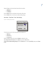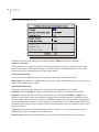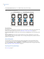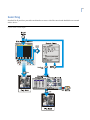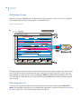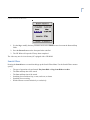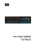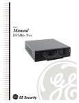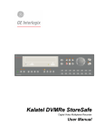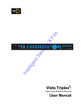
1
GE
Security
StoreSafe Pro II
User Manual
Copyright
Copyright © 2005, GE Security Inc. All rights reserved.
This document may not be copied in whole or in part, or otherwise reproduced except as
specifically permitted under US copyright law, without the prior written consent from GE.
Document number/revision: 0150-0306A.
Disclaimer
The information in this document is subject to change without notice. GE, in keeping pace with
technological advances, is a company of product innovation. Therefore, it is difficult to ensure
that all information provided is entirely accurate and up-to-date. GE accepts no responsibility
for inaccuracies or omissions and specifically disclaims any liabilities, losses, or risks, personal
or otherwise, incurred as a consequence, directly or indirectly, of the use or application of any
of the contents of this document.
This publication may contain examples of screen captures and reports used in daily operations.
Examples may include fictitious names of individuals and companies. Any similarity to names
and addresses of actual businesses or persons is entirely coincidental.
Trademarks and patents
GE and the GE monogram are registered trademarks of General Electric.
StoreSafe Pro II product and logo are registered trademarks of GE Security.
Other trade names used in this document may be trademarks or registered trademarks of the
manufacturers or vendors of the respective products.
Software license agreement
GE software supplied with GE products is proprietary and furnished under license and can be
used or copied only in accordance with the license terms.
THE ENCLOSED PROGRAM IS FURNISHED SUBJECT TO THE TERMS AND CONDITIONS OF THIS
AGREEMENT. RETENTION OF THE PROGRAM FOR MORE THAN 30 DAYS, OPENING OF THE
SEALED WRAPPER, IF ANY, SURROUNDING THE PROGRAM, OR USE OF THE PROGRAM IN ANY
MANNER WILL BE CONSIDERED ACCEPTANCE OF THE AGREEMENT TERMS. IF THESE TERMS ARE
NOT ACCEPTABLE, RETURN THE UNUSED PROGRAM AND ANY ACCOMPANYING DOCUMENTATION
TO GE FOR A FULL REFUND OF THE LICENSE FEE PAID. (FOR INFORMATION REGARDING THE
RETURN OF PROGRAMS ENCODED OR INCORPORATED WITHIN EQUIPMENT, CONTACT THE
NEAREST GE SALES OFFICE.)
Intended use
Use this product only for the purpose for which it was designed; refer to the data sheet and user
documentation. For the latest product information, contact your GE sales representative or visit
us online at www.gesecurity.com.
FCC compliance
This equipment has been tested and found to comply with the limits for a Class A digital device,
pursuant to part 15 of the FCC Rules. These limits are designed to provide reasonable
protection against harmful interference when the equipment is operated in a commercial
environment. This equipment generates, uses, and can radiate radio frequency energy and, if
not installed and used in accordance with the instruction manual, may cause harmful
interference to radio communications.
You are cautioned that any changes or modifications not expressly approved by the party
responsible for compliance could void the user's authority to operate the equipment.
Contact
Direct all inquiries about GE’s legal policies with regard to this product to:
Director of Legal Services
GE Security
12345 SW Leveton Drive
Tualatin, OR 97062-9938 USA
iii
Contents
Introduction . . . . . . . . . . . . . . . . . . . . . . . . . . . . . . . . . . . . . . . . . . . . . . . . . . . . . . . . . . . . . . . . . . . . . . . . . . . . . . . . . . . . 1
Conventions used in this document. . . . . . . . . . . . . . . . . . . . . . . . . . . . . . . . . . . . . . . . . . . . . . . . . . . . . . . . . . . . . . . . .1
Safety terms and symbols . . . . . . . . . . . . . . . . . . . . . . . . . . . . . . . . . . . . . . . . . . . . . . . . . . . . . . . . . . . . . . . . . . . . . . . . .1
StoreSafe Pro II Overview . . . . . . . . . . . . . . . . . . . . . . . . . . . . . . . . . . . . . . . . . . . . . . . . . . . . . . . . . . . . . . . . . . . . . . . . 2
Product Description. . . . . . . . . . . . . . . . . . . . . . . . . . . . . . . . . . . . . . . . . . . . . . . . . . . . . . . . . . . . . . . . . . . . . . . . . . . . . . . .2
Passwords . . . . . . . . . . . . . . . . . . . . . . . . . . . . . . . . . . . . . . . . . . . . . . . . . . . . . . . . . . . . . . . . . . . . . . . . . . . . . . . . . . . . . . . .3
Unpacking . . . . . . . . . . . . . . . . . . . . . . . . . . . . . . . . . . . . . . . . . . . . . . . . . . . . . . . . . . . . . . . . . . . . . . . . . . . . . . . . . . . . . . . .4
Installation Environment . . . . . . . . . . . . . . . . . . . . . . . . . . . . . . . . . . . . . . . . . . . . . . . . . . . . . . . . . . . . . . . . . . . . . . . . . . .5
Associated Equipment . . . . . . . . . . . . . . . . . . . . . . . . . . . . . . . . . . . . . . . . . . . . . . . . . . . . . . . . . . . . . . . . . . . . . . . . . . . . .6
The Back Panel . . . . . . . . . . . . . . . . . . . . . . . . . . . . . . . . . . . . . . . . . . . . . . . . . . . . . . . . . . . . . . . . . . . . . . . . . . . . . . . . . . . .6
Power-Up . . . . . . . . . . . . . . . . . . . . . . . . . . . . . . . . . . . . . . . . . . . . . . . . . . . . . . . . . . . . . . . . . . . . . . . . . . . . . . . . . . . . . . . 11
StoreSafe Pro II Basic Operations . . . . . . . . . . . . . . . . . . . . . . . . . . . . . . . . . . . . . . . . . . . . . . . . . . . . . . . . . . . . . . . . 14
Principal Operating Modes . . . . . . . . . . . . . . . . . . . . . . . . . . . . . . . . . . . . . . . . . . . . . . . . . . . . . . . . . . . . . . . . . . . . . . . 14
The Front Panel. . . . . . . . . . . . . . . . . . . . . . . . . . . . . . . . . . . . . . . . . . . . . . . . . . . . . . . . . . . . . . . . . . . . . . . . . . . . . . . . . . 14
Live Viewing . . . . . . . . . . . . . . . . . . . . . . . . . . . . . . . . . . . . . . . . . . . . . . . . . . . . . . . . . . . . . . . . . . . . . . . . . . . . . . . . . . . . . 15
Playback . . . . . . . . . . . . . . . . . . . . . . . . . . . . . . . . . . . . . . . . . . . . . . . . . . . . . . . . . . . . . . . . . . . . . . . . . . . . . . . . . . . . . . . . 16
Recording . . . . . . . . . . . . . . . . . . . . . . . . . . . . . . . . . . . . . . . . . . . . . . . . . . . . . . . . . . . . . . . . . . . . . . . . . . . . . . . . . . . . . . . 18
Display Options. . . . . . . . . . . . . . . . . . . . . . . . . . . . . . . . . . . . . . . . . . . . . . . . . . . . . . . . . . . . . . . . . . . . . . . . . . . . . . . . . . 19
Active Cameos . . . . . . . . . . . . . . . . . . . . . . . . . . . . . . . . . . . . . . . . . . . . . . . . . . . . . . . . . . . . . . . . . . . . . . . . . . . . . . . . . . 21
Sequencing . . . . . . . . . . . . . . . . . . . . . . . . . . . . . . . . . . . . . . . . . . . . . . . . . . . . . . . . . . . . . . . . . . . . . . . . . . . . . . . . . . . . . 21
On-screen Indicators . . . . . . . . . . . . . . . . . . . . . . . . . . . . . . . . . . . . . . . . . . . . . . . . . . . . . . . . . . . . . . . . . . . . . . . . . . . . 22
Triplex Mode . . . . . . . . . . . . . . . . . . . . . . . . . . . . . . . . . . . . . . . . . . . . . . . . . . . . . . . . . . . . . . . . . . . . . . . . . . . . . . . . . . . . 24
The Print Image Button . . . . . . . . . . . . . . . . . . . . . . . . . . . . . . . . . . . . . . . . . . . . . . . . . . . . . . . . . . . . . . . . . . . . . . . . . . 26
The Record CD Button . . . . . . . . . . . . . . . . . . . . . . . . . . . . . . . . . . . . . . . . . . . . . . . . . . . . . . . . . . . . . . . . . . . . . . . . . . . 27
Menu System Overview . . . . . . . . . . . . . . . . . . . . . . . . . . . . . . . . . . . . . . . . . . . . . . . . . . . . . . . . . . . . . . . . . . . . . . . . . 29
Menu Notation In This Manual. . . . . . . . . . . . . . . . . . . . . . . . . . . . . . . . . . . . . . . . . . . . . . . . . . . . . . . . . . . . . . . . . . . . 29
Accessing The Menu System . . . . . . . . . . . . . . . . . . . . . . . . . . . . . . . . . . . . . . . . . . . . . . . . . . . . . . . . . . . . . . . . . . . . . 29
Available Menus . . . . . . . . . . . . . . . . . . . . . . . . . . . . . . . . . . . . . . . . . . . . . . . . . . . . . . . . . . . . . . . . . . . . . . . . . . . . . . . . . 29
Menus In This Manual . . . . . . . . . . . . . . . . . . . . . . . . . . . . . . . . . . . . . . . . . . . . . . . . . . . . . . . . . . . . . . . . . . . . . . . . . . . . 30
Navigating The Menu System . . . . . . . . . . . . . . . . . . . . . . . . . . . . . . . . . . . . . . . . . . . . . . . . . . . . . . . . . . . . . . . . . . . . 30
Menu Shortcuts. . . . . . . . . . . . . . . . . . . . . . . . . . . . . . . . . . . . . . . . . . . . . . . . . . . . . . . . . . . . . . . . . . . . . . . . . . . . . . . . . . 30
The Main Menu . . . . . . . . . . . . . . . . . . . . . . . . . . . . . . . . . . . . . . . . . . . . . . . . . . . . . . . . . . . . . . . . . . . . . . . . . . . . . . . . . . 31
Time/Date. . . . . . . . . . . . . . . . . . . . . . . . . . . . . . . . . . . . . . . . . . . . . . . . . . . . . . . . . . . . . . . . . . . . . . . . . . . . . . . . . . . . . . . 31
Record . . . . . . . . . . . . . . . . . . . . . . . . . . . . . . . . . . . . . . . . . . . . . . . . . . . . . . . . . . . . . . . . . . . . . . . . . . . . . . . . . . . . . . . . . . 35
Alarms . . . . . . . . . . . . . . . . . . . . . . . . . . . . . . . . . . . . . . . . . . . . . . . . . . . . . . . . . . . . . . . . . . . . . . . . . . . . . . . . . . . . . . . . . . 45
Macro. . . . . . . . . . . . . . . . . . . . . . . . . . . . . . . . . . . . . . . . . . . . . . . . . . . . . . . . . . . . . . . . . . . . . . . . . . . . . . . . . . . . . . . . . . . 52
Motion Detection . . . . . . . . . . . . . . . . . . . . . . . . . . . . . . . . . . . . . . . . . . . . . . . . . . . . . . . . . . . . . . . . . . . . . . . . . . . . . . . . 54
Camera Setup . . . . . . . . . . . . . . . . . . . . . . . . . . . . . . . . . . . . . . . . . . . . . . . . . . . . . . . . . . . . . . . . . . . . . . . . . . . . . . . . . . . 59
Audio Setup . . . . . . . . . . . . . . . . . . . . . . . . . . . . . . . . . . . . . . . . . . . . . . . . . . . . . . . . . . . . . . . . . . . . . . . . . . . . . . . . . . . . . 63
Quick Wave Setup . . . . . . . . . . . . . . . . . . . . . . . . . . . . . . . . . . . . . . . . . . . . . . . . . . . . . . . . . . . . . . . . . . . . . . . . . . . . . . . 63
iv
StoreSafe Pro II
User Manual
Communications. . . . . . . . . . . . . . . . . . . . . . . . . . . . . . . . . . . . . . . . . . . . . . . . . . . . . . . . . . . . . . . . . . . . . . . . . . . . . . . . . 64
Front Panel Lock . . . . . . . . . . . . . . . . . . . . . . . . . . . . . . . . . . . . . . . . . . . . . . . . . . . . . . . . . . . . . . . . . . . . . . . . . . . . . . . . . 69
Factory Settings . . . . . . . . . . . . . . . . . . . . . . . . . . . . . . . . . . . . . . . . . . . . . . . . . . . . . . . . . . . . . . . . . . . . . . . . . . . . . . . . . 69
Passwords. . . . . . . . . . . . . . . . . . . . . . . . . . . . . . . . . . . . . . . . . . . . . . . . . . . . . . . . . . . . . . . . . . . . . . . . . . . . . . . . . . . . . . . 70
The Operator Menu . . . . . . . . . . . . . . . . . . . . . . . . . . . . . . . . . . . . . . . . . . . . . . . . . . . . . . . . . . . . . . . . . . . . . . . . . . . . . . 72
Alarms . . . . . . . . . . . . . . . . . . . . . . . . . . . . . . . . . . . . . . . . . . . . . . . . . . . . . . . . . . . . . . . . . . . . . . . . . . . . . . . . . . . . . . . . 75
Alarm Input . . . . . . . . . . . . . . . . . . . . . . . . . . . . . . . . . . . . . . . . . . . . . . . . . . . . . . . . . . . . . . . . . . . . . . . . . . . . . . . . . . . . . . 75
Alarm Output . . . . . . . . . . . . . . . . . . . . . . . . . . . . . . . . . . . . . . . . . . . . . . . . . . . . . . . . . . . . . . . . . . . . . . . . . . . . . . . . . . . . 75
Alarm Acknowledge . . . . . . . . . . . . . . . . . . . . . . . . . . . . . . . . . . . . . . . . . . . . . . . . . . . . . . . . . . . . . . . . . . . . . . . . . . . . . . 75
On-screen Displays During Alarms. . . . . . . . . . . . . . . . . . . . . . . . . . . . . . . . . . . . . . . . . . . . . . . . . . . . . . . . . . . . . . . . 75
Alarm Operations During Playback . . . . . . . . . . . . . . . . . . . . . . . . . . . . . . . . . . . . . . . . . . . . . . . . . . . . . . . . . . . . . . . 75
Alarm History Box. . . . . . . . . . . . . . . . . . . . . . . . . . . . . . . . . . . . . . . . . . . . . . . . . . . . . . . . . . . . . . . . . . . . . . . . . . . . . . . . 76
Searching For Recorded Alarms . . . . . . . . . . . . . . . . . . . . . . . . . . . . . . . . . . . . . . . . . . . . . . . . . . . . . . . . . . . . . . . . . . 76
Searching . . . . . . . . . . . . . . . . . . . . . . . . . . . . . . . . . . . . . . . . . . . . . . . . . . . . . . . . . . . . . . . . . . . . . . . . . . . . . . . . . . . . . 77
Disk Analysis Screen . . . . . . . . . . . . . . . . . . . . . . . . . . . . . . . . . . . . . . . . . . . . . . . . . . . . . . . . . . . . . . . . . . . . . . . . . . . . . 78
Quick Archive to CD . . . . . . . . . . . . . . . . . . . . . . . . . . . . . . . . . . . . . . . . . . . . . . . . . . . . . . . . . . . . . . . . . . . . . . . . . . . . . . 78
Search Filters . . . . . . . . . . . . . . . . . . . . . . . . . . . . . . . . . . . . . . . . . . . . . . . . . . . . . . . . . . . . . . . . . . . . . . . . . . . . . . . . . . . . 79
Retail Search . . . . . . . . . . . . . . . . . . . . . . . . . . . . . . . . . . . . . . . . . . . . . . . . . . . . . . . . . . . . . . . . . . . . . . . . . . . . . . . . . . . . 80
Search Results . . . . . . . . . . . . . . . . . . . . . . . . . . . . . . . . . . . . . . . . . . . . . . . . . . . . . . . . . . . . . . . . . . . . . . . . . . . . . . . . . . . 84
WebBrowser . . . . . . . . . . . . . . . . . . . . . . . . . . . . . . . . . . . . . . . . . . . . . . . . . . . . . . . . . . . . . . . . . . . . . . . . . . . . . . . . . . . 86
WaveBrowser Overview and Controls . . . . . . . . . . . . . . . . . . . . . . . . . . . . . . . . . . . . . . . . . . . . . . . . . . . . . . . . . . . . . 87
StoreSafe Pro II WaveLink . . . . . . . . . . . . . . . . . . . . . . . . . . . . . . . . . . . . . . . . . . . . . . . . . . . . . . . . . . . . . . . . . . . . . . . . 89
Technical Specifications . . . . . . . . . . . . . . . . . . . . . . . . . . . . . . . . . . . . . . . . . . . . . . . . . . . . . . . . . . . . . . . . . . . . . . . . 91
RS232 Event Generation/Text Insertion Protocol . . . . . . . . . . . . . . . . . . . . . . . . . . . . . . . . . . . . . . . . . . . . . . . . . . 93
Message Structure . . . . . . . . . . . . . . . . . . . . . . . . . . . . . . . . . . . . . . . . . . . . . . . . . . . . . . . . . . . . . . . . . . . . . . . . . . . . . . . 93
Message Type . . . . . . . . . . . . . . . . . . . . . . . . . . . . . . . . . . . . . . . . . . . . . . . . . . . . . . . . . . . . . . . . . . . . . . . . . . . . . . . . . . . 93
Alarm/Event Fields . . . . . . . . . . . . . . . . . . . . . . . . . . . . . . . . . . . . . . . . . . . . . . . . . . . . . . . . . . . . . . . . . . . . . . . . . . . . . . . 94
Alarm Actions. . . . . . . . . . . . . . . . . . . . . . . . . . . . . . . . . . . . . . . . . . . . . . . . . . . . . . . . . . . . . . . . . . . . . . . . . . . . . . . . . . . . 94
Event Actions . . . . . . . . . . . . . . . . . . . . . . . . . . . . . . . . . . . . . . . . . . . . . . . . . . . . . . . . . . . . . . . . . . . . . . . . . . . . . . . . . . . . 95
RS232 Remote Control Protocol . . . . . . . . . . . . . . . . . . . . . . . . . . . . . . . . . . . . . . . . . . . . . . . . . . . . . . . . . . . . . . . . . 96
Front Panel Button Emulation. . . . . . . . . . . . . . . . . . . . . . . . . . . . . . . . . . . . . . . . . . . . . . . . . . . . . . . . . . . . . . . . . . . . . 96
Configuration and Status . . . . . . . . . . . . . . . . . . . . . . . . . . . . . . . . . . . . . . . . . . . . . . . . . . . . . . . . . . . . . . . . . . . . . . . . . 97
Macro Tables . . . . . . . . . . . . . . . . . . . . . . . . . . . . . . . . . . . . . . . . . . . . . . . . . . . . . . . . . . . . . . . . . . . . . . . . . . . . . . . . . 100
Scheduled Macro Table . . . . . . . . . . . . . . . . . . . . . . . . . . . . . . . . . . . . . . . . . . . . . . . . . . . . . . . . . . . . . . . . . . . . . . . . .101
Warranty and Service . . . . . . . . . . . . . . . . . . . . . . . . . . . . . . . . . . . . . . . . . . . . . . . . . . . . . . . . . . . . . . . . . . . . . . . . . 102
Factory Service . . . . . . . . . . . . . . . . . . . . . . . . . . . . . . . . . . . . . . . . . . . . . . . . . . . . . . . . . . . . . . . . . . . . . . . . . . . . . . . . .102
Warranty and Return Information . . . . . . . . . . . . . . . . . . . . . . . . . . . . . . . . . . . . . . . . . . . . . . . . . . . . . . . . . . . . . . .102
Contacting technical support. . . . . . . . . . . . . . . . . . . . . . . . . . . . . . . . . . . . . . . . . . . . . . . . . . . . . . . . . . . . . . . . . . . 104
Online publication library. . . . . . . . . . . . . . . . . . . . . . . . . . . . . . . . . . . . . . . . . . . . . . . . . . . . . . . . . . . . . . . . . . . . . . . .104
1
Introduction
This is the GE StoreSafe Pro II User Manual for models SDVR-4PII-xxx, SDVR-10PII-xxx, and SDVR16PII-xxx. This document includes an overview of the product and detailed instructions explaining:
•
•
how to install and configure; and
how to operate the StoreSafe Pro II.
There is also information describing how to contact technical support if you have questions or concerns.
To use this document effectively, you should have the following minimum qualifications:
•
•
a basic knowledge of CCTV systems and components; and
a basic knowledge of electrical wiring and low-voltage electrical connections.
Read these instructions and all ancillary documentation entirely before installing or operating this product. The
most current versions of this and related documentation may be found on our website. Refer to Online
publication library on page 104 for instructions on accessing our online publication library.
Note:
A qualified service person, complying with all applicable codes, should perform all required hardware installation.
Conventions used in this document
The following conventions are used in this document:
Bold
Menu items and buttons.
Italic
Emphasis of an instruction or point; special terms.
File names, path names, windows, panes, tabs, fields, variables, and other GUI elements.
Titles of books and various documents.
Monospace
Text that displays on the computer screen.
Programming or coding sequences.
Blue italic
Hyperlinks to cross-references, related topics, and URL addresses.
Safety terms and symbols
These terms may appear in this manual:
CAUTION
Cautions identify conditions or practices that may result in damage to the equipment or other property.
WARNING
Warnings identify conditions or practices that could result in equipment damage or serious personal injury.
2
StoreSafe Pro II
User Manual
StoreSafe Pro II Overview
Product Description
StoreSafe Pro II is a video multiplexer capable of recording from multiple cameras to an internal hard drive
while simultaneously providing playback. Unlike outdated time-lapse VCRs, StoreSafe Pro II records highresolution pictures. Digital recording improves playback quality over VCRs, and eliminates the hassle of
cleaning heads, changing tapes or servicing motors. Depending on the setup, StoreSafe Pro II can store from a
few hours to more than 3 years of color images.
Programmable search features eliminate time consuming fast-forwarding or rewinding of tapes, while
searching for critical data. Search for recorded images or events by alarm, time, date, video loss, or camera
number. StoreSafe Pro II also features convenient front panel buttons for one-touch printing and archiving (CD
writing). In addition, StoreSafe Pro II uses advanced compression technology for extremely high video
compression per megabyte.
CAUTION
This products primary purpose is to furnish video multiplexing and recording. Although the unit has alarm
handling and motion detection functions, they are considered secondary features. This unit should not be
the only alarm device on site.
3
Features
•
•
•
•
•
•
•
•
•
•
•
•
•
•
•
•
•
•
•
•
•
•
•
Multiplexer functionality with built-in digital recording.
Simultaneous recording, playback, and live multiscreen viewing.
60pps (pictures per second) recording of up to 16 cameras.
Advanced video compression.
Remote programming and control through the RS232 and ethernet ports.
View live or recorded images remotely using WaveReader software.
Dual monitor displays.
Video motion detection (intrusion and activity).
Displays include full screen, sequenced, picture-in-picture, and multiscreens.
Alarm handling with History Log.
Retail text search.
Archive Video onto CD-Rs with built in CD writer.
Continuous Recording with simultaneous Archiving.
Clock synchronization with Network Server.
Dynamic IP addressing (DHCP).
Support for Dynamic Domain Name Server (DDNS).
Covert camera recording (recording without display).
Auto-daylight savings time change function.
Alarm notification via email.
Integrated WaveBrowser Software.
Support for over a dozen languages.
Hard disk monitoring and testing features.
Playback and live audio via WaveReader on audio supported models.
Passwords
Passwords are provided to limit access to menus and certain functions. Two levels of password security are
provided:
•
•
Operator: Limited menu access, only the Operator menu is available.
Installer: Complete menu access, both the Main and Operator menus are available.
As a security measure, it is recommended that the Operator and Installer passwords be changed after
installation is complete (see Passwords on page 70). Store the passwords in the administrator’s secure files.
4
StoreSafe Pro II
User Manual
Default Passwords
Table 1.
Four-channel units
Changeable by
user
Default password
Provides access to the Operator and System
View menus.
Yes
Press ‘ENTER’ 4 Times
Provides access to all on-screen menus.
Yes
3444
Factory Defaults Installer
Resets the multiplexer to the factory
defaults (except the time, date, email
addresses, and email IP address).
No
4111
Language
Installer
Provides access to the On-screen Language
menu.
No
1414
Ethernet Access
Reset
Installer
Deactivates the ethernet password, so that
the unit may be accessed by any PC
equipped with WaveReader.
No
1111
Password type
Access level
Function
Operator
Operator
Installer
Installer
Table 2.
Ten and sixteen-channel units
Password type
Access level
Function
Changeable by user
Default password
Operator
Operator
Provides access to the
Operator and
SystemView menus.
Yes
Press ‘ENTER’ 4 Times
Installer
Installer
Provides access to all
on-screen menus.
Yes
3477
Factory Defaults
Installer
Resets the multiplexer
to the factory defaults
(except the time, date,
email addresses, and
email IP address).
No
8111
Language
Installer
Provides access to the
On-screen Language
menu.
No
5415
Ethernet Access Reset
Installer
Deactivates the
ethernet password, so
that the unit may be
accessed by any PC
equipped with
WaveReader.
No
1111
Unpacking
Check the package and contents for visible damage. If any components are damaged or missing, do not attempt
to use the unit, contact the supplier immediately. If the unit must be returned, it must be shipped in the original
packing box.
5
Package Contents
•
•
•
•
•
•
•
•
•
The StoreSafe Pro II unit.
The Alarm Interface Circuit Board (P/N 0090-0077).
Accessory PCB (P/N 0900-0127).
The User Manual (P/N 0150-0306).
A WaveReader Software CD (P/N 0151-0005).
The WaveReader Software Manual (P/N 0150-0143).
WaveWatch User Manual (P/N 0150-0189).
Power Supply (P/N 4310-0020).
Power Cords (110 VAC P/N 4310-0002) and (220 VAC P/N 4310-0001).
Installation Environment
Power: Ensure that the installation site’s AC power is stable and within the rated voltage of the 12
Volt DC power supply. If the site’s AC power is likely to have spikes or power dips, use power line
conditioning or an Uninterruptable Power Supply (UPS).
Ventilation: Ensure that the location planned for the installation of the unit is well ventilated. Take
note of the locations of the cooling vents in the unit’s enclosure, and ensure that they are not
obstructed.
Temperature: Consider the unit’s operating temperature (0 to 40 °C) and non-condensing humidity
specifications (10% to 80%) before choosing an installation location. Extremes of heat or cold
beyond the specified operating temperature limits may cause the unit to fail. Do not install the unit
on top of other hot equipment. Leave space between rack mounted units.
Moisture: Do not expose the unit to rain or moisture. Moisture can damage the internal components.
Do not install the unit near sources of water.
Chassis: Other equipment may be placed on top of the unit if it weighs less than 35 pounds (16
kilograms).
Handling Hard Disks: This unit has a built-in hard disk (HD). Be sure to observe the following
points carefully when operating, setting up, and servicing the unit.
•
•
•
•
Do not subject the unit to shocks or vibration. Shocks and vibration may damage the HD or cause
corruption of the data stored on the unit.
Do not move the unit while the power is turned on.
Do not move the unit for 30 seconds after tuning off the power.
When transporting the unit, pack it securely using the original packing materials.
6
StoreSafe Pro II
User Manual
Associated Equipment
Associated equipment in a typical security system could contain the following items:
•
•
•
•
•
•
Two monitors
Printer with Printer Server connected via ethernet cable.
Video cameras: Composite video, 1 volt peak-to-peak.
Alarm input devices: Pressure sensors, motion detectors, etc.
Alarm output devices: Buzzers, Sirens, Flashing Lights, etc.
A PC connected via ethernet cable.
For instructions regarding the connection of the associated security equipment in your system, please consult
the instruction manual of the associated equipment.
The Back Panel
Figure 1. SDVR-16PII -xxx model shown
1. Camera Inputs: BNC connector, looping. Auto Terminating.
2. Composite Monitor-A and -B Output: Composite video output with BNC style connector.
3. Power Input: For connecting the power supply.
4. Alarm I/O: For connecting alarm inputs, and alarm output relays.
5. RS232 Port 1: For modem connection and external control of the unit.
6. Aux Port: For connecting the Accessory PCB for Audio inputs and outputs.
7. RS485 Port 2 Connector: For connecting to keyboard and other RS485 devices.
8. RS485 Port 1 Connector: For connecting to keyboard and other RS485 devices.
9. RS232 Port 2: For Event Generation and ASCII Text insertion.
10. 10/100 Ethernet Port: For connecting to remote PC via ethernet network.
7
Camera Inputs
There are two BNC jacks for each camera. Either jack can receive a camera signal. The signal is looped
(directly connected to the other jack), making the camera signal available to other equipment.
The camera input connectors are Auto Terminating.
Cable:
75-Ohm coaxial
Connectors:
BNC
Auto terminating:
Yes
Passive looping
Yes
This means that the input signal will automatically be terminated with 75-Ohms unless a 2nd cable is connected
to the 2nd BNC connector of the same camera input. Make sure there is 75-Ohm termination at the end of the
video line if the signal is looped through StoreSafe Pro II.
Time base correction is performed during digital capture. As a result, cameras do not require synchronization.
See Main Menu / Camera Setup / Camera Disable on page 61 for information about disabling unused camera
jacks in the menu system.
Composite Monitor Output
When connecting directly from StoreSafe Pro II to the monitor, select the 75-Ohm impedance setting on the
monitor.
Cable:
75-Ohm coaxial
Connectors:
BNC
If an additional device is connected to the monitor’s looping output, set the termination of the additional device
as 75-Ohm, and set the termination of the monitor as Hi-Z (High Impedance).
Alarm I/O Port
The back panel of the unit is equipped with an Alarm Port (DB-25 style connector).Do not attempt to wire
directly to the DB-25 connector on the back panel.
Connect the Alarm PCB (supplied with the unit) to the Alarm Port. Wire all alarm inputs to the Alarm PCB per
the pin out specifications shown below.
8
StoreSafe Pro II
User Manual
Figure 2. The alarm PCB
Pin 1: Alarm Input 1.
Pin 13: Alarm Input 13.
Pin 2: Alarm Input 2.
Pin 14 Alarm Input 14.
Pin 3: Alarm Input 3.
Pin 15: Alarm Input 15.
Pin 4: Alarm Input 4.
Pin 16: Alarm Input 16.
Pin 5: Alarm Input 5.
Pin 17: Alarm Output Relay #1.
Pin 6: Alarm Input 6.
Pin 18: Ground.
Pin 7: Alarm Input 7.
Pin 19: Ground.
Pin 8: Alarm Input 8.
Pin 20: Ground.
Pin 9: Alarm Input 9.
Pin 21: Alarm Output Relay #1 Common.
Pin 10: Alarm Input 10.
Pin 22: Alarm Output Relay #2.
Pin 11: Alarm Input 11.
Pin 23: External Alarm Silence and Acknowledge
Input.
Pin 12: Alarm Input 12.
Pin 25: Alarm Output Relay #2 Common.
Active alarm inputs vary by StoreSafe Pro II model. 4 channel units have 4 active alarm inputs, 10 channel
units have 10 active alarm inputs and 16 channel units have 16 active alarm inputs.
Alarm Input
An alarm condition can be activated by devices such as pressure pads, passive infrared detectors, door
switches, or other similar devices.
Alarm Relay Output
The alarm relay output is activated when an alarm condition exists. The alarm output is only active for the
duration of the alarm. Alarm output relay #2 is activated whenever video loss is detected.
9
Alarm relays can be programmed in the menu system to respond to macros. See Alarms on page 45 for
information about configuring the alarms in the menu system.
Output:
Normally open zero potential relay contact.
Voltage:
30V (max)
Current:
500mA (max)
External Alarm Acknowledge Input
Connect a switch or similar device to ground this pin in order to acknowledge an alarm condition, and silence
associated buzzers and relays. Connect from pin 23 to either pin 18, 19, or 20 (ground pins).
External device:
Note:
Normally open zero potential relay contact.
All specifications subject to change without notice. GE Security believes all specifications to be correct at time of
printing, but no liability is assumed for omissions or errors.
RS485 Connector
Shields are grounded at one end, preferably at the StoreSafe Pro II end.
See Menu / Communications / RS485 on page 67 for information about configuring the RS485 network address
settings in the menu system.
Wire type:
#24 AWG, twisted pair with shield (2-wire)
Connector type:
RJ-45
Max cable length:
3200 feet/1000 meters
RJ-45 Pin Configuration For RS485 Port
Table 3.
RS485 port pin configuration
Pin
Use
Pin
Use
1
Ground (shield)
5
Not connected
2
Not connected
6
Network - VE
3
Network + VE
7
Ground (shield)
4
Not connected
8
Not connected
Ethernet Port
The cable connection configuration depends on your network configuration:
•
•
For a StoreSafe Pro II that connects directly to a Hub or Switch, use a straight through connection.
For a StoreSafe Pro II that connects directly to a PC, use a cross over connection.
10
StoreSafe Pro II
User Manual
Consult with your MIS personnel for the specific type of configuration. See Main Menu / Communications /
Ethernet Settings on page 67 for information about configuring the ethernet settings in the menu system.
Wire type:
Cat 5
Connector type:
RJ-45
Max. cable length
100 meters/328 feet
Min. cable length
6 feet/1.8 meters
Hub wiring configuration:
Straight through
PC wiring configuration:
Cross over
RJ-45 Pin Configuration For Ethernet Port
Table 4.
Ethernet pin configuration
Pin
Use
Pin
Use
1
TX+
5
Not connected
2
TX-
6
RX-
3
RX+
7
Not connected
4
Not connected
8
Not connected
RS232 Port 1
For a Modem connection or remote control of unit. See Main Menu / Communications / RS232 on page 64 for
information about configuring the modem settings in the menu system. See RS232 Remote Control Protocol on
page 96 for RS232 Remote Control Protocols.
Table 5.
DB-9 pin configuration for port 1
Pin
Use
Pin
Use
Pin
Use
1
DCD
4
DTR
7
RTS
2
RX
5
Ground
8
CTS
3
TX
6
Not connected
9
Not connected
11
RS232 Port 2
For Event Generation and ASCII Text Insertion.
Table 6.
RJ-45 pin configuration for RS232 port 2
Pin
Use
Pin
Use
1
Ground
5
TXD
2
Reserved
6
Not connected
3
Not connected
7
Ground
4
RXD
8
Reserved
Power-Up
Use the diagram below to secure the power cord to the back panel.
Figure 3. Securing the power cord
It is important that the power-up procedures be followed carefully. The unit uses its auto-detect feature to
detect camera signals during power-up, and configure itself automatically.
12
StoreSafe Pro II
User Manual
Power-up procedure
Once the system installation is complete, apply power in the following order:
1. Energize the monitors and all of the cameras.
2. Energize StoreSafe Pro II.
Table 7.
Power Supply input
Power supply input
Voltage:
12 Volt DC
Power:
60 watt (5 amp)
Connector:
2.1mm barrel, center positive
Once power is applied to the unit, it will begin its power-up procedure. The unit will begin by displaying the
software version on Monitor-A, and then the unit will be ready for operation.
Check Video Input Quality
Check the picture quality by selecting each camera for full screen display. If the picture quality is poor, check
the following items:
•
•
•
•
•
The BNC connections.
The loop-through terminations.
The video levels of incoming signals.
The possibility of ground loops.
Consult the camera’s installation instructions for additional information about proper camera setup.
Check Record And Playback Quality
Record for at least three minutes at the default record rate. Then play back the recording, selecting each camera
for full screen display. Check the playback picture quality.
AUX Port
Figure 4. The accessory PCB
The back panel of the StoreSafe Pro II is equipped with an Aux Port (DB-9 style connector).
Do not attempt to wire directly to the DB-9 connector on the back panel.
13
Connect the Accessory PCB to the AUX port to access the Audio features. Wire the audio input and output to
the Accessory PCB per the pin out specifications shown below.
Pin 1: Not Used.
Pin 6: Not Used.
Pin 2: Audio Out.
Pin 7: Ground.
Pin 3: Ground.
Pin 8: Not Used.
Pin 4: Audio In.
Pin 9: Ground.
Pin 5: Ground.
GND: Ground.
WARNING
The use of clandestine listening and recording devices is forbidden by Federal Law as well as other
State and Municipal Jurisdictions. Please review local and Federal Law prior to the installation or
operation of this equipment to ensure that you are in legal compliance with the Authorities having
Jurisdiction.
14
StoreSafe Pro II
User Manual
StoreSafe Pro II Basic Operations
Principal Operating Modes
StoreSafe Pro II has five principal modes of operation:
•
•
•
•
•
Live Viewing.
Playback.
Recording.
Printing.
Archiving to CD.
Each mode is discussed in detail later in this section.
The Front Panel
Figure 5. SDVR-16PII-xxx model shown
1. Power Indicator: Indicates power on/off condition.
2. Monitor Selection Button: Monitor A.
3. Monitor Selection Button: Monitor B.
4. Multiscreen Selection Buttons: Various Multiscreen buttons depending on the StoreSafe Pro II
model.
15
5. Alarm Button: Allows user to acknowledge and silence alarms.
6. Sequence Button: Sequences camera views.
7. Zoom Button: Provides a 2X digital zoom.
8. Function Button: Used in conjunction with Camera Buttons to run Macros.
9. Camera Selection Number Buttons: Camera numbers 1 through 16.
10. CD Recorder: For recording data to CD.
11. Record CD Button: One-touch archiving of selected video onto CD using the built-in CD-Writer.
12. Print Image Button: One-touch printing of displayed image.
13. Record Button: Used to Start and Stop Recording.
14. Reverse Play Button: Playback in Reverse.
15. Freeze Button (Pause): Freezes camera images on-screen in Live mode. Pauses Playback.
16. Stop Button: To stop Playback and return to Live mode.
17. Play Forward Button: Begins Playback.
18. Search Button: Access to stored video data.
19. Jog/Shuttle: Controls Playback speed and Menu selections.
20. Menu Button: Provides access to on-screen menus.
21. Enter Button: Confirms selection in menus.
Live Viewing
Multiscreen Display
In Live Multiscreen mode, press one of the Multiscreen buttons to activate the multiscreen display on
Monitor-A. Pressing the multiscreen button with the maximum multiscreens (i.e. 16-way or 10-way)
repeatedly will cycle through all the available multiscreens. Multiscreen displays are not available on MonitorB. Live Multiscreens are displayed with gray borders. For detailed information about Multiscreen displays, see
Display Options on page 19.
Figure 6. Available multiscreen display by channel
16
StoreSafe Pro II
User Manual
Multiscreen Display With Sequencing
If a multiscreen display does not include all of the cameras, the remaining cameras can be sequenced in the
bottom right cameo. While in a multiscreen display, press the Sequence button to begin sequencing.
Full Screen Display
Select any camera for Full Screen display by pressing the Number button of the desired camera. Pressing the
Camera number button again displays the Status Display Box. Pressing the same button a third time displays
any associated ATM or cash register ASCII text, see ATM/POS Text Display on page 24.
Sequenced Full Screen Display
While in a Full Screen display, press the Sequence button to begin full screen sequencing.
Zooming
To activate the 2x digital zoom, select the full screen display of the camera you wish to zoom, then press the
Zoom button. Zooming will be indicated by the LED located directly above the Zoom button. Zooming is also
indicated as ZOOM on the primary monitor. Zooming works with frozen and non-frozen images. Zoomed
images can also be frozen.
While Zoomed, rotate the Jog/Shuttle to Pan and Tilt across the image. Please note, the camera does not move
during digital Pan/Tilt.
Press the Zoom button again to cancel the Zoom operations.
Note:
If the Zoom button is pressed while in a multiscreen display, the camera from the last active cameo is selected for full
screen display. Press the Zoom button again to activate the Zoom operation.
Freezing
Pressing the Freeze button freezes all camera images on-screen. Full Screen freezing is indicated as FRZ onscreen. Multiscreen freezing is indicated as * (a flashing asterisk) in each frozen cameo.
Individual cameos can be frozen in Active Cameo mode (see Entering Active Cameo Mode on page 21).
Press the Freeze button again or any camera button to cancel Freeze operations.
Selecting Monitor-B
To control Monitor-B, press the Monitor B selection button. The Monitor-B LED will light to indicate that the
number keypad now controls Monitor-B. Press the Monitor A button to return the keypad control to MonitorA.
Playback
Playback always displays on Monitor A. Playback multiscreen borders are black, as opposed to the gray
borders of the live multiscreens. Monitor B continues to display live full screen images in playback mode. To
begin playback, press the Play Forward or Reverse Play button.
17
Play Forward
When the Play Forward button is pressed, the unit will play forward at the rate the data was recorded. While in
Playback mode, the user may change the playback direction, playback speed, etc. To return to Play Forward
operations, press the Play Forward button.
Reverse Play
To begin reverse playback, press the Reverse Play button.
Fast Forward
During playback, rotate the Shuttle (the outer dial) clockwise to view data at a higher than normal rate.
Increasing the amount of rotation increases the rate of playback.
AutoPause
During playback, moving the Jog (the inner dial) in any direction will freeze playback. Depress the Freeze or
any play button to continue playback.
Rewind
During playback, rotate the Shuttle counter-clockwise to view data (in reverse) at a higher than normal rate.
Increasing the amount of rotation increases the rate of playback.
Freeze
During playback, press the Freeze button. This feature pauses all full screen and multiscreen images
Single Frame Advance & Single Frame Rewind
During Freeze or Pause mode, rotate the Jog (the inner dial) to view the frame directly before or after the frame
displayed on-screen.
Stop Playback
To stop playback and return to Live Multiscreen mode on Monitor A, press the Stop button.
Multiscreen Display
During Playback, press one of the Multiscreen buttons to activate a multiscreen display. Pressing the
multiscreen button with the maximum multiscreens (i.e. 16-way or 10-way) repeatedly will cycle through all
the available multiscreens. The 6-way and PIP multiscreen displays are not available in Playback mode.
Multiscreen Display With Sequencing
If a multiscreen display does not include all of the cameras, the remaining cameras can be sequenced in the
bottom right cameo. While in a multiscreen display, press the Sequence button to begin sequencing.
18
StoreSafe Pro II
User Manual
Full Screen Display
Select any camera for Full Screen display by pressing the Number button of the desired camera. Pressing the
Camera number button again displays the Status Display Box. Pressing the same button a third time displays
any associated ATM or cash register ASCII text.
Sequenced Full Screen Display
While in a Full Screen display, press the Sequence button to begin full screen sequencing.
Zooming
To activate the 2x digital zoom, select the full screen display of the camera you wish to zoom, then press the
Zoom button. Zooming will be indicated by the LED located directly above the Zoom button. Zooming is also
indicated as ZOOM on the monitor. Zooming works with frozen and non-frozen images. Zoomed images can
also be frozen.
While Zoomed, use the Jog/Shuttle to Pan and Tilt across the image. Please note, the camera does not move
during digital Pan/Tilt.
Press the Zoom button again, or another camera button to cancel the Zoom operations.
Note:
If the Zoom button is pressed while in a multiscreen display, the camera from the last active cameo is selected for full
screen display. Press the Zoom button again to activate the Zoom operation.
Searching Recorded Data
StoreSafe Pro II has a powerful search interface feature that allows the user to search for data on the internal
hard disk. The user may search the data for previous recording sessions, text insertion, and alarm conditions.
Because the search interface is so dynamic, the search interface is covered in detail in a separate section of this
manual. See Searching on page 77.
Recording
To begin recording, press the Record button. Recording will be indicated by the LED located directly above the
Record button. The unit always starts recording at the end of previously recorded data. The unit will continue
recording until the record button is pressed again, unless Record Lock is ON.
StoreSafe Pro II also remembers its current record mode in the event of power loss. If the unit was recording
during a power loss, then when power is restored the unit will put itself back in that mode.
Monitor Displays During Recording
Multiscreen Live and Playback displays on Monitor A and Monitor B are not affected by recording operations.
19
Figure 7. Display mode matrix
Display Options
Available Multiscreen Displays
Press the Multiscreen buttons to activate the multiscreen display. Pressing the individual multiscreen button
will display the corresponding multiscreen. Pressing the 16-way or 10-way button repeatedly will cycle
through all the available multiscreens.
20
StoreSafe Pro II
User Manual
Figure 8. Available multiscreens
The multiscreen display is limited to the number of camera inputs on the unit.
Four-Channel unit: Only capable of displaying 4-way multiscreen and PIP.
Ten-Channel unit: Capable of displaying 10-way through 4-way multiscreen and PIP.
Sixteen-Channel unit: Capable of displaying 16-way through 4-way multiscreen and PIP.
The camera assignments for each multiscreen is retained (in non-volatile memory) for both Live and Playback
multiscreen mode on Monitor A.
PIP: Use the Jog/Shuttle to adjust the location and size of the PIP display. Please note, that the PIP display is
only available on Monitor A in Live mode.
21
Active Cameos
A cameo is defined as any cell within a multiscreen display. Active Cameo mode allows the user to access and
edit each cameo individually.
Entering Active Cameo Mode
While viewing a multiscreen, enter Active Cameo mode by pressing the Enter button. Active Cameo mode is
indicated on-screen by flashing the number and titles of the active cameo and the LED above the Enter button
is lit. By default, the top left cameo is activated.
Selecting Cameos
Select a cameo using the Jog/Shuttle to navigate the multiscreen. Rotating the Jog selects the next screen up or
down a row. Rotating the shuttle selects the next screen in numerical order. The active cameo will always be
indicated by the flashing camera number and titles.
Selecting Cameras
Display any camera in the active cameo by pressing the Number button of the desired camera. Once a camera
has been selected, the active cameo advances to the next cameo on the right.
The camera selection only changes the multiscreen currently being displayed. Each multiscreen must be
configured separately. Changes to the multiscreen display are saved in non-volatile memory, and will be
retained even if power is removed from the unit.
Freezing
Press the Freeze button to freeze the image in the selected cameo. Each frozen cameo is indicated as * (a
flashing asterisk) on-screen.
Press the Freeze button again to cancel Freeze operations.
Sequencing
The sequencing feature allows a camera to be displayed briefly on-screen, before advancing to the next camera
in the sequence list. The default sequence list displays each camera in numerical order.
Dwell Time
The dwell time is the amount of time each camera is displayed on-screen before advancing to the next camera.
The default dwell time is 3 seconds.
Autolist™ Custom Sequence List
The Autolist™ feature allows the user to create a custom sequence list, controlling the order the cameras are
displayed and the dwell time. Separate Autolists may be created for Monitor A (Live and Playback mode) and
Monitor B (Live mode). Using the Monitor button, select the monitor to be programmed. Then, using a
Number button, select any camera for full screen display.
22
StoreSafe Pro II
User Manual
Note:
The unit must be in Full Screen Display mode before starting to create the sequence list. This initial camera is not part
the sequence list.
To begin recording the Autolist™ sequence: Press the Alarm button and Sequence button simultaneously.
Autolist Program mode is indicated as PGM on-screen. Recording starts when the first camera number is
pressed. Press the camera numbers in the order you wish them to appear on-screen. The amount of time
between button presses determines the Dwell Time. During sequence list programming, pressing any button
other than a Number button or the Sequence button voids the sequence list.
To end the recording: Press the Sequence button. The amount of time between pressing the last Number
button and the Sequence button determines the dwell time for the final camera in the sequence list.
Returning To The Default Sequence List
The default sequence list is all cameras in numeric order with a three second dwell time.
To return the unit to the default sequence list, go to the Main Menu / Factory Settings menu.
CAUTION
Initiating the Factory Setting menu command returns all settings (except the time, date, email addresses,
and email IP address) back to the original factory defaults. This will cause the loss of any custom settings.
Sequencing In Cameos
While viewing a multiscreen display, additional cameras (cameras not shown in the multiscreen display) can be
sequenced in the lower right hand cameo by pressing the Sequence button. The sequence list is not
programmable. Press the Sequence button again to cancel sequencing.
On-screen Indicators
There are five types of on-screen indicators.
•
•
•
•
•
Camera Titles: Displays the camera number and the camera title.
Status Indicators: Displays Time, Date, and Hard Disk record time left.
Conditional Indicators: Displays indicators for Freeze, Zoom, Alarm, Motion Detection, Video loss,
Autolist™ Program mode, Macro Record and Macro Playback mode.
Status Display Box: Displays Archive Device, Network status and Image Quality Setting (Playback
mode only).
Text Display Box: Displays ATM/POS Text data.
Camera Titles
Camera Titles are displayed on either the upper or lower corner of the left hand side of the screen. The camera
title can be changed in the menu system (see Main Menu / Camera Setup / Camera Titles on page 59). The user
can change display position and color. See below.
23
Changing Position And Color Of Title And Status Indicators
Camera Titles: To change the color and position of the camera titles, select a camera for full screen display,
then press the Enter button to advance to the next display setting. Repeatedly pressing the Enter button
advances the display settings through the sequence show in the table on the right.
Example: Select Camera 1 for full screen display. Using the Enter button, cycle through the sequence shown
on the right. Each time the position cycle is completed, the unit advances the Status Indicator color. Choose
Black, White or Gray.
Table 8.
Camera title position and color sequence
Position
Color
Top left
Black
Top left
White
Top left
Gray
Bottom left
Black
Bottom left
White
Bottom left
Gray
Status Indicators
Status indicators are displayed on the upper right hand corner of the screen.
Status indicators include:
•
•
Time and Date (these can be turned off in the menu system, see Main Menu / Time/Date / Time / Date
Display on page 33). The Time and Date format can also be changed in the menu system.
Time remaining on Hard Disk(s).
24
StoreSafe Pro II
User Manual
Conditional Indicators
Table 9.
Conditional Indicators
Condition
Full screen indicator
Multiscreen indicator
Alarm
ALM
A in cameo of camera in alarm
Autolist™ Program mode
PGM
PGM
Freeze
FRZ
* (Asterisk) in frozen cameo
Macro Record mode
F followed by macro number
F followed by macro number
Motion Detection
M
M in cameo w/ motion detection
Video loss
VDL
V in cameo with video loss
Zoom
ZOOM
ZOOM
Status Display Box
A Status Display Box can be viewed by pressing the Camera Number button twice. Status Indicators include:
On Live Fullscreen:
•
•
Archive Status: Not Connected, Not Ready, Ready, Ejecting, Play, and timeleft. Timeleft indicates
the amount of time before the archive medium is full (Only available if the unit has Background
Archiving turned On).
Network: Displays all current Network connections. Normal connection is displayed as ip.ip or --- if
there is no connection. Live connections are displayed as E1: ip.ip, E2: ip.ip, etc. (where ip.ip
represents the last 2 bytes of the IP Address). POTS connection is displayed as IP 1.1.
On Playback Fullscreen:
•
All the above, including Image Quality Setting: High, Medium, Standard.
ATM/POS Text Display
Pressing the Camera Number a third time displays an ATM/POS text display. This feature can be used during
live viewing mode to verify that StoreSafe Pro II is receiving ATM/POS text, or in Playback mode to review
recorded text and video.
Triplex Mode
Triplex mode allows the display of both live and playback images to appear on Monitor A simultaneously. Live
images have gray borders, while playback images have black borders.
To enter triplex mode, press the Play Forward button while in Play Forward mode. Alternatively, press the Play
Reverse button while in Play Reverse mode. Both the Play Forward LED and the Stop LED turn on to indicate
that the unit is in triplex mode.
Monitor B always displays a fullscreen live display.
25
Play Forward
When in Play Forward mode and the Play Forward button is pressed, the unit will enter the triplex mode of
operation. When Play Forward is pressed again, the unit will revert back into the normal Playback mode. While
in the triplex mode, if reverse play is in progress, the Play Forward button will change the playback direction.
Reverse Play
When in Reverse Play mode and the Reverse Play button is pressed, the unit will enter the triplex mode of
operation. When Reverse Play is pressed again, the unit will revert back into the normal Playback mode. While
in the triplex mode, if forward play is in progress, the Reverse Play button will change the playback direction.
Fast Forward
During triplex mode, rotate the Shuttle (the outer dial) clockwise to view playback images at a higher than
normal rate. Increasing the amount of rotation increases the rate of playback. Live images are not affected.
Rewind
During triplex mode, rotate the Shuttle counter-clockwise to view playback images (in reverse) at a higher
than normal rate. Increasing the amount of rotation increases the rate of playback. Live images are not affected.
Freeze
During triplex mode, pressing the Freeze button pauses all multiscreen images, both Live and Playback.
Single Frame Advance & Single Frame Rewind
During Freeze or Pause mode, rotate the Jog (the inner dial) to view the frame directly before or after the frame
displayed on-screen. Only the playback images are affected.
Stop
To stop triplex mode and return to Live mode on Monitor A, press the Stop button.
Multiscreen Display
During triplex mode, press one of the Multiscreen buttons to activate a multiscreen display. The 6-way and
PIP multiscreen displays are not available in triplex mode. For detailed information about Multiscreen
displays, see Display Options on page 19. The Live and Playback images in a multiscreen display may be
transposed by pressing the multiscreen button that corresponds with the current multiscreen display. E.g. If the
current display is a 4-way multiscreen with the 2 top cameos being playback images and the rest of the cameos
being live images, pressing the 4-way multiscreen button will result in the 2 top cameos being live and the rest
of the cameos being playback images.
Multiscreen Display With Sequencing
If a multiscreen display does not include all of the cameras, the remaining cameras can be sequenced in the
bottom right cameo. While in a multiscreen display, press the Sequence button to begin sequencing. For
26
StoreSafe Pro II
User Manual
detailed information about sequencing, see Sequencing on page 21. This feature is not available on the 4channel units.
Full Screen Display
Select any camera for Full Screen display by pressing the Number button of the desired camera. Pressing the
Camera number button again displays the Status Display Box. Pressing the same button a third time displays
any associated ATM or cash register ASCII text.
Sequenced Full Screen Display
While in a Full Screen display, press the Sequence button to begin full screen sequencing. The sequence list is
programmable. For detailed information about programming the sequence list see Sequencing on page 21.
Zooming
To activate the 2x digital zoom, select the full screen display of the camera you wish to zoom, then press the
Zoom button. Zooming will be indicated by the LED located directly above the Zoom button. Zooming is also
indicated as ZOOM on the monitor. Zooming works with frozen and non-frozen images. Zoomed images can
also be frozen.
While Zoomed, use the Jog/Shuttle to Pan and Tilt across the image. Please note, the camera does not move
during digital Pan/Tilt.
Press the Zoom button again, or another camera button to cancel the Zoom operations.
Note:
If the Zoom button is pressed while in a multiscreen display, the camera from the last active cameo is selected for full
screen display. Press the Zoom button again to activate the Zoom operation.
The Print Image Button
Pressing the Print Image button will print the currently displayed image. If a 4-way multiscreen is the display
mode, StoreSafe Pro II will switch to a single image display of the last selected fullscreen camera, freeze the
image, and send to the default printer.
Printer Setup
The following equipment and conditions are required for the operation of the Print Image button.
Equipment
HP DeskJet 3820
Hawking Print Server PN7127P
Conditions
The Printer and Print Server must be connected to the same local network as StoreSafe Pro II.
StoreSafe Pro II must know the Print Servers IP address. The IP address can be input under Main Menu /
Communications / Ethernet Settings (See Main Menu / Communications / Ethernet Settings on page 67).
27
The Printer and Print Server must be On-line and Operational.
The Record CD Button
To record video to CD for archival or law enforcement purposes, follow the steps listed below:
1. Push the Open/Close button on the CD Writer. When the tray opens insert a blank recordable CD (CDR) into the CD tray. Push the Open/Close button on the CD Writer to close the CD tray.
2. The unit begins writing the QuickWave software to the CD so that the files can later be viewed on any
PC with a CD drive. When QuickWave is finished loaded on OK message will appear. Click OK to
clear.
3. Wait a few moments for the CD Writer to come ready. To check the archive devices status use the
Status Display Box. The Status Display Box can be viewed by pressing the Camera Number button
twice. The LED will turn green when the device is ready.
4. Press the Record CD Button. If the CD Writer is ready the Archive Incident screen will appear,
5. Use the Jog to modify the time parameters and use the Shuttle to move between the Start and Stop
fields.
6. Press the Record button on the front panel when satisfied. A progress bar appears on the lower right of
the monitor.
7. The CD Writer will open the CD tray when completed.
The video may now be viewed on any PC equipped with a CD-ROM.
Figure 9. The archive incident screen
The Record CD Button and Live Viewing
Pressing the Record CD button while viewing live video will cause the Archive Incident screen to appear. The
unit takes the latest recording as its stop time and fits as much of the previous recording as the CD will hold.
The time and size of the archived video can be adjusted by various amounts depending on where on the Hard
Disk the data lies.
28
StoreSafe Pro II
User Manual
The Record CD Button and Playback
Pressing the Record CD button while playing recorded video will cause the Archive Incident screen to appear.
The Start and Stop times displayed will be determined by when in the video the Record CD button was pushed.
The unit will choose an equal (if possible) amount of time before and after the selection. The time and size of
the archived video can be adjusted by various amounts depending on where on the Hard Disk the data lies.
The Record CD Button and the Disk Analysis Screen
Pressing the Record CD button while the Disk Analysis screen is displayed will cause the Archive Incident
screen to appear. The Start and Stop times displayed will be determined by when in the video the pointer was
when the button was pushed. The unit will choose an equal (if possible) amount of time before and after the
selection. The time and size of the archived video can be adjusted by various amounts depending on where on
the Hard Disk the data lies.
Storage Overhead
There is a certain amount of overhead required when writing data to a CD. Each selected file gets written to a
separate file when it is stored on the CD. The overhead for the first track is approximately 24 MB. Each
subsequent track requires about 15 MB.
Note:
For example:
•
•
•
Archiving a 40 MB file requires 64 MB (40 + 24 = 64)
Archiving a 40 and a 44 MB file requires 123 MB ((40 + 24) + (44 + 15) = 123 MB)
Archiving a 40, 44, and 82 MB file requires 220 MB ((40 + 24) + (44 + 15) + (82 + 15) = 220MB)
29
Menu System Overview
Menu Notation In This Manual
In the following sections, there are headings like this:
Main Menu / Time/Date / Set Time
Meaning: From the Main Menu, select Time/Date, then press the Enter button. The Time/Date menu will
appear. From the Time/Date menu, select Set Time, then press the Enter button. A pop-up or pull-down menu
will appear.
Selected Items
Items selected in the menu system are represented with reverse highlighted text.
Accessing The Menu System
Enter the menu system by pressing the Menu button. A Password Box will appear on the primary monitor.
Enter either the:
•
•
Operator Password: Providing limited access to the menu system. Only the Operator menu is
available.
Installer Password: Providing complete menu access.
Use the Number buttons to enter the appropriate password.
Default passwords are provided in the beginning of this manual, see Passwords on page 3.
Available Menus
Figure 10. Available menus
Main
Operator
Time/Date
About StoreSafe
Record
Time/Date Display
Alarms
Titles Display
Macro
Alarm History
Motion Detection
Operator Password
Camera Setup
QuickWave Setup
Audio Setup
Communications
Front Panel Lock
Factory Settings
Passwords
30
StoreSafe Pro II
User Manual
Menus In This Manual
Each menu is covered in detail in this chapter of this manual. Menus and menu items appear in the manual in
the same order they appear on-screen.
•
•
Main Menu
Operator Menu
Navigating The Menu System
Selecting a Menu from the Menu Bar: When the menu system is first accessed, only the menu bar is
displayed. Use the Shuttle to select the desired menu.
Opening the Drop Down Menus: Rotate the Jog.
Navigating in Menus: Rotate the Jog to highlight items in the drop-down menus.
Selecting Menu Items: Hit the ENTER button to select the highlighted menu item.
Exiting Menus: Press the Menu button to exit a menu. From the menu bar, press the Menu button to exit the
menu system completely.
Figure 11. Menu navigation
Menu Shortcuts
Zoom Button: In menu lists that have 2 settings per camera, the Zoom button will toggle all selections. This
provides a quick and easy way to enable or disable all cameras for a particular feature.
Camera Button: In menu lists that provide settings per camera, a particular camera may be accessed directly
by pressing on the associated camera button. Rotate the Shuttle to modify the setting.
31
The Main Menu
Main Menu Overview
The Main menu contains the majority of programmable options for StoreSafe Pro II. Each item in the Main
menu is described in detail in this section of the manual.
Main menu items appear in this section in the same order they appear in the menu.
Time/Date
Figure 12. The Time/date menu
Set Time
Set Date
Set Date Format
Time/Date Display
Set Region
Use this menu to specify:
•
•
•
•
•
The time and date.
The date format: MM/DD/YY, YY/MM/DD, or DD/MM/YY.
Which monitors will display the time and date.
Set Regional Daylight Savings Time.
Setup clock synchronization between StoreSafe Pro II and Network Server.
Main Menu / Time/Date / Set Time
Figure 13. Time setup menu
1. Rotate the Shuttle to navigate, highlight HH MM SS.
2. Press the Enter button, the highlighting will move to the row of numbers.
32
StoreSafe Pro II
User Manual
3. Enter the time in Hours, Minutes, and Seconds. Rotate the Jog to change the values and the Shuttle to
navigate.
4. Press the Enter button to confirm the selection and exit the edit mode.
5. To save the changes and exit the menu: Rotate the Jog to select [OK], then press the Enter button.
6. To exit the menu without making changes: Rotate the Jog to select [CANCEL], then press the
Enter button.
Main Menu / Time/Date / Set Date
Figure 14. Date setup menu
1. Press the Enter button, the highlighting will move to the row of numbers.
2. Enter the date in Months, Days, Years. The day of the week is calculated automatically. Rotate the Jog
to change the values and the Shuttle to navigate.
3. Press the Enter button to confirm the selection and exit the edit mode.
4. To save the changes and exit the menu: Rotate the Jog to select [OK], then press the Enter button.
5. To exit the menu without making changes: Rotate the Jog to select [CANCEL], then press the
Enter button.
Main Menu / Time/Date / Set Date Format
Figure 15. Date format setup menu
33
Rotate the Jog to set the desired date format. Select from either:
•
•
•
MM/DD/YY
DD/MM/YY
YY/MM/DD
Press the Enter button to confirm the selection and exit the menu.
Press the Menu button to exit the menu without making changes.
Main Menu / Time/Date / Time / Date Display
Figure 16. Time/date display setup menu
Use this menu to specify if the time and date will be displayed on:
•
•
•
•
Monitor-A.
Monitor-B.
Both Monitors.
Not Displayed
Rotate the Jog to navigate, then rotate the Shuttle to change the values.
Save changes and exit the menu: Select [OK], then press the Enter button.
Exit the menu without making changes: Press the Menu button, or select [CANCEL], then press the Enter
button.
34
StoreSafe Pro II
User Manual
Main Menu / Time/Date / Set Region
Figure 17. Regional settings menu
Use this menu to set the region for the Auto Daylight Savings Time
feature. Choices are:
•
•
•
•
OFF: Clock will not be changed automatically, but can still be adjusted by one hour using the daylight
saving macros.
USA: DST starts at 02:00 on the first Sunday in April. DST ends at 02:00 on the last Sunday in
October.
Includes: United States (except Hawaii, American Samoa, Guam, Puerto Rico, Virgin Islands, parts of
Indiana and Arizona) and Canada (except Saskatchewan).
EUR: DST starts at 01:00 GMT on the last Sunday in March. DST ends at 01:00 GMT on the last
Sunday in October. Includes: European Union Countries.
AUS: DST starts at 02:00 on the last Sunday in October. DST ends at 03:00 on the last Sunday in
March. Includes: South Australia, Victoria, ACT, NSW. Excludes: Tasmania.
The Time Zone must be set correctly to ensure that the DST adjustments are made at the right time. It is also
required for accurate email time stamping.
Note:
The clock will only be automatically adjusted once on a given time and date. If you manually set the clock back before
the last DST change, the time will not get automatically adjusted again for that same time change.
Main Menu / Time/Date / Network Time Setup
Use this menu to enable/disable and specify how often time synchronization should occur between StoreSafe
Pro II and the Network Server. The Region /Time Zone must be setup prior to enabling the option.
Update Interval, Select from: Enable, Disable, Once per Day, Twice per Day, and Once per Hour
NTP Primary Server: Enter IP Address of Primary Server.
NTP Backup Server: Enter IP Address of Backup Server.
1. To save changes and exit the menu: Select [OK], then press the Enter button.
35
2. To exit the menu without making changes: Press the Menu button, or select [CANCEL], and then
press the Enter button.
Figure 18. Network time setup menu
Record
Figure 19. The record menu
36
StoreSafe Pro II
User Manual
Use this menu to:
•
•
•
•
•
•
•
•
•
•
•
Specify a schedule for recording.
Specify the record quality: High, Medium, or Standard.
Specify if a camera is to be used for event recording, time-lapse recording, or both.
Specify the time-lapse record rate per camera.
Specify the event record rate per camera.
Specify the activity record rate per camera.
Specify the alarm record rate.
Setup the Alarm/Event actions.
Perform disk maintenance by performing a Disk Test, Deleting, Un-deleting, or Destroying previously
recorded video.
Set the Record Lock feature.
Set the Auto Delete Mode.
Main Menu / Record / Record Timer
Figure 20. The record time menu
Use this menu to setup Preset Record Timer Events.
1. Rotate the Shuttle to select a timed event from the list.
2. Press the ENTER button to enter the Edit mode.
3. Rotate the Shuttle to navigate to the desired field.
4. Rotate the Jog to change the values of the selected field.
5. Press the Enter button to exit the Edit mode.
6. Rotate the Jog to highlight the [OK] field and press the ENTER button to save the changes.
37
Main Menu / Record / Record Quality
Figure 21. Record quality menu
Use this menu to specify the record quality for each camera. Decreasing the record quality decreases the
amount of disk space required to store the images, due to a higher compression scheme.
Table 10.
Record quality
Picture quality
Disk space needed
High
Excellent
Most
Medium
Good
Medium
Standard
Fair
Least
1. Rotate the Jog to navigate, and the Shuttle to change the values.
2. To save changes and exit the menu: Select [OK], then press the Enter button.
3. Exit the menu without making changes: Press the Menu button, or select [CANCEL], and then press
the Enter button.
38
StoreSafe Pro II
User Manual
Main Menu / Record / Event/Timelapse
Figure 22. Event camera settings menu
Event Camera Settings
Camera 01: Event + TL
Camera 02: TL
Camera 03: Event
Camera 04: TL
:
:
Camera 16: Event + TL
[CANCEL]
[OK]
Use this menu to specify how each camera will record during normal and event conditions.
TL: Records at the Time-lapse Record Rate under normal conditions. Does not change record rate during an
event.
Event: Records during events at the Event Record Rate. Camera does not record under normal conditions.
Event + TL: Records at the Time-lapse Record Rate under normal conditions. Records at the Event Record
Rate during events.
Event overview
About Events: An Event is an action that the unit acknowledges by recording at the Event Record Rate, yet it
is not cause for an Alarm. Events may be created two ways, via RS232 text insertion and Activity detection.
Example of an Event: A camera is pointed at the front door inside the lobby during business hours. With the
Event Camera Settings Type set to Event, the unit does not record while the doorway is empty. When activity
motion detection senses that someone is entering or leaving the doorway, the unit begins recording at the Event
Record Rate and stops recording when the motion ceases.
RS232 Event: See RS232 Event Generation/Text Insertion Protocol on page 93 for information about
generating an Event via RS232, and optionally inserting ASCII text to mark the Event.
Activity Detection Event: See Main Menu / Motion Detection / Setup Parameters on page 55 for detailed
information about configuring activity detection as an event in the menu system.
Main Menu / Record / Timelapse Record Rate
The unit records at the Timelapse Record Rate under normal conditions, when there are no alarms, events, or
activity present. Record rates are measured in both Pictures Per Second (pps) and Seconds Per Picture (spp).
The maximum record rate per camera is inversely proportional to the number of cameras connected to the unit.
The fewer cameras connected, the higher the maximum record rate for each camera, and vice versa. The
39
maximum record rate for multiple cameras is 24pps (NTSC). The maximum record rate for a single camera
is60pps (NTSC).
The bottom right corner of the menu contains a record duration calculator. The top line indicates the estimated
recording time for the unit in Time-lapse record mode only. The bottom line indicates the estimated recording
time, taking into consideration the amount of time the unit will spend in Activity, Event, and/or Alarm record
mode.
Figure 23. Timelapse record rate menu
Timelapse Record Rate
Camera
1 : 0.40 pps 2.5 spp
Camera
2 : 0.29 pps 3.5 spp
Camera
3 : 0.34 pps 2.9 spp
Camera
4 : 0.57 pps 1.8 spp
:
:
:
Camera 15 : 0.40 pps 2.5 spp
Camera 16 : 0.40 pps 2.5 spp
8 days 5 h (TL)
[CANCEL]
[OK]
8 days 5 h (Total)
1. Rotate the Jog to navigate, and the Shuttle to change the values.
2. To save changes and exit the menu: Select [OK], and then press the Enter button.
3. To exit the menu without making changes: Press the Menu button, or select [CANCEL], then press
the Enter button.
Main Menu / Record / Event Record Rate
The unit will record at the Event Record Rate when an Event is activated. Events can be activated by RS232
event generation or activity detection. See Main Menu / Record / Event/Timelapse on page 38.
Record rates are measured in both Pictures Per Second (pps) and Seconds Per Picture (spp).
The maximum record rate per camera is inversely proportional to the number of cameras connected to the unit.
The fewer cameras connected, the higher the maximum record rate for each camera, and vice versa. The
maximum record rate for multiple cameras is 24pps (NTSC). The maximum record rate for a single camera is
60pps (NTSC.
The bottom right corner of the menu contains a record duration calculator. The top line indicates the estimated
recording time of the cameras in Event record mode only. The bottom line indicates the estimated recording
time, taking into consideration the amount of time the unit will spend in Time-lapse, Activity, Event, and/or
Alarm record mode.
40
StoreSafe Pro II
User Manual
Figure 24. The event record rate menu
Event Record Rate
Camera
1 : 0.40 pps 2.5 spp
Camera
2 : 0.29 pps 3.5 spp
Camera
3 : 0.34 pps 2.9 spp
Camera
4 : 0.57 pps 1.8 spp
% Time: 4%
:
:
Estimate of the % of time each
camera will typically spend in
Event mode. For example if you
expect to have about 20 total
events each day, each lasting 3
minutes on average, then the %
of the time will be 4%.
(1 hour/24 hours)
:
Camera
9 : 0.40 pps 2.5 spp
Camera 10 : 0.40 pps 2.5 spp
125 days 8 h (EVENT)
[CANCEL]
[OK]
10 days 7 h (Total)
1. Rotate the Jog to navigate, and the Shuttle to change the values.
2. To save changes and exit the menu: Select [OK], and then press the Enter button.
3. To exit the menu without making changes: Press the Menu button, or select [CANCEL], then press
the Enter button.
Main Menu / Record / Activity Record Rate
The unit will record at the Activity Record Rate when the camera is in normal Timelapse Record Mode and
activity is detected in the camera scene. Activity should not be linked to Event, in which case the Event Record
Rate will be used.
Record rates are measured in both Pictures Per Second (pps) and Seconds Per Picture (spp).
The maximum record rate per camera is inversely proportional to the number of cameras connected to the unit.
The fewer cameras connected, the higher the maximum record rate for each camera, and vice versa. The
maximum record rate for multiple cameras is 24pps (NTSC). The maximum record rate for a single camera is
60pps (NTSC).
The bottom right corner of the menu contains a record duration calculator. The top line indicates the estimated
recording time of the cameras in Activity record mode only. The bottom line indicates the estimated recording
time, taking into consideration the amount of time the unit will spend in Time-lapse, Activity, Event, and/or
Alarm record mode.
41
Figure 25. Activity record rate
1. Rotate the Jog to navigate, and the Shuttle to change the values.
2. To save changes and exit the menu: Select [OK], and then press the Enter button.
3. To exit the menu without making changes: Press the Menu button, or select [CANCEL], then press
the Enter button.
Main Menu / Record / Alarm Record Rate
During an alarm, the unit records at the alarm record rate. The bottom of the menu contains a record duration
calculator. The top line indicates the estimated recording time of the cameras in Alarm record mode only. The
bottom line indicates the estimated recording time, taking into consideration the amount of time the unit will
spend in Time-lapse, Activity, Event, and/or Alarm record mode.
The configuration of the Alarm Record Rate is closely associated with the Alarm Record Mode. For detailed
information about configuring the Alarm Record Mode, see Main Menu / Record / Alarm/Event Actions on
page 42.
Figure 26. The alarm record rate menu
42
StoreSafe Pro II
User Manual
1. Rotate the Jog to navigate, and the Shuttle to change the values.
2. To save changes and exit the menu: Select [OK], and then press the Enter button.
3. To exit the menu without making changes: Press the Menu button, or select [CANCEL], then press the
Enter button.
Main Menu / Record / Alarm/Event Actions
Use this menu to specify how the unit will record during Alarm and Event actions.
Figure 27. The alarm/event actions menu
Alarm/Event Actions
Pre Event Duration
5
Post Event Duration
0
Pre Alarm Duration
0
Alarm Record Mode
Interleaved
ACTIVITY Link to Event
Yes
[CANCEL]
[OK]
Pre Event Duration: The unit will record up to 5 seconds of data ahead of the event trigger, at the Event
Record Rate. Select from 0 to 5 seconds.
Post Event Duration: The unit will record up to 250 seconds after the completion of the Event, at the Event
Record Rate. Select from 0 to 250 seconds.
Pre Alarm Duration: The unit will record up to 5 seconds of data ahead of the alarm trigger, at the Alarm
Record Rate. Select from 0 to 5 seconds.
Alarm Record Mode: Select from Interleaved or Exclusive.
ACTIVITY Link to Event: Select from Yes or No.
Main Menu / Record / Disk Maintenance
Figure 28. The disk maintenance menu
43
Use the Jog to select from the following options, then press the Enter button to begin.
Delete: Delete all data from the hard disk (with the possibility of restoring it).
Undelete: Restore data that has been deleted, but not yet overwritten.
Destroy: Erase all data from the hard disk permanently, without the possibility
of restoring it. Selecting this option brings up a confirmation dialog box.
Test: Provides access to the Disk Test Setup menu which features disk test and
monitoring options.
Disk Test Setup Menu
The Disk Test Setup menu provides several testing options including the test time, frequency, and duration.
Disk Test: Options include Disable, Test Now, Test Periodically. The Test Periodically option runs the Disk
Test at the specified frequency. The Disk Tests run in the background and will not interfere with normal
operations.
Test Frequency in hours: From 0 to 1000 hours between tests.
Test Duration: This option is for the type of test to run; Fast or Thorough. The Thorough test will test
significantly more sectors than the Fast test. GE recommends using the Thorough test. The Fast test can miss
some disk failures.
Figure 29. The disk test setup menu
Use the Jog to move between the menu fields and the Shuttle for the selections within the fields. When
satisfied with the selections select OK and press the Enter button to execute.
The Disk Test will run in the background and will not interfere with normal operations. Once the disk test is
done, a message will appear on the screen indicating the test result.
44
StoreSafe Pro II
User Manual
Figure 30. Disk test results
Press the Enter button to clear from the display.
Should a disk test fail, several actions will performed:
•
•
An icon will be displayed indicating disk failure.
It is displayed on Monitor A on the bottom of
the screen in the middle. This icon will only disappear when the disk is replaced.
If the Notify Alarm or Notify Record email option is enabled in the Email Notification Setup Screen,
an email will be sent indicating that a disk failure occurred.
Main Menu / Record / Record Lock
Figure 31. The record lock menu
Use this menu to set the Record Lock feature. This feature disables the front panel
record button. Setting Record Lock to ON will start the unit recording if it is not currently
in the Record mode.
Main Menu / Record / ADM (Auto Delete Mode)
The ADM feature prevents the unit from displaying or archiving any search results that are older than the
specified number of days. This feature may be required by law in some jurisdictions. If required by local
authorities, the ADM feature must be turned On by selecting between 1 and 99 days. Typically this feature is
turned Off.
45
Figure 32. The auto delete mode menu
Alarms
Figure 33. The alarms menu
Use this menu to configure the alarm handling features of the unit.
CAUTION
StoreSafe Pro II’s primary function is to furnish video multiplexing and recording with a multiscreen display.
Although the unit has alarm handling and motion detection functions, these are considered secondary
features. This unit should not be the only alarm device on site.
46
StoreSafe Pro II
User Manual
Main Menu / Alarms / Input Configuration
Figure 34. Input configuration menu
Configure the alarm inputs as either Normally Open or Normally Closed.Configure inputs as follows.
Normally Open Zero Potential Relay Contact: Configure in menu as Normally Open.
Normally Closed Zero Potential Relay Contact: Configure in menu as Normally Closed
TTL Active High: Configure in menu as Normally Closed.
TTL Active Low: Configure in menu as Normally Open.
Open Collector Active On: Configure in menu as Normally Open.
Open Collector Active Off: Configure in menu as Normally Closed.
Main Menu / Alarms / Alarm Latch
Figure 35. The alarm latch menu
This feature determines how the unit latches alarm conditions.
Selecting from the following options.
Latched: The alarm is activated until it is silenced and acknowledged by the user.
47
Transparent: The alarm is active only while receiving alarm input. The alarm condition is canceled when the
alarm input ceases.
Timed Out: The alarm condition is latched for the amount of time selected in this menu, then it is
automatically silenced and acknowledged. If the alarm input exceeds the duration specified in this menu, the
unit silences and acknowledges the alarm when the alarm input ceases. Select the timeout duration, the range is
from 1 to 250 seconds.
Transparent alarms cannot be silenced and acknowledged. If transparent mode is preferred, but the ability to
silence and acknowledge alarms is desired, select Timed Out and set the Alarm Timeout to two seconds.
Main Menu / Alarms / Enable/Disable
Figure 36. The alarms enable/disable menu
Use this menu to Enable or Disable the alarm inputs.
Select from the following options:
•
•
•
Individual Enable: Allow the user to access the Alarm Enable submenu, and enable or disable alarm
inputs on a per camera basis.
Enable All
Disable All
Rotate the Jog to navigate, and the Shuttle to change the values.
Save changes and exit the menu: Select [OK], then press the Enter button.
Exit the menu without making changes: Press the Menu button, or select [CANCEL], then press the Enter
button.
48
StoreSafe Pro II
User Manual
Main Menu / Alarms / Alarm History
Figure 37. The alarm history window
Alarm History Box
001- 02/04 18:40:32 16
002- 02/15 12:00:10 11
003- 02/28 10:10:20 08
:
:
010- 03/15 05:12:16 04
[OK]
Use this window to view a list of the 100 most recent alarms. Alarms are displayed 10 at a time. Rotate the Jog
to scroll through the alarms.
Information displayed in this window is:
•
•
•
•
The alarms number in the list.
The date of the alarm (month and day).
The time of the alarm (hours, minutes, and seconds).
The number of the camera inputs in alarm.
49
Main Menu / Alarms / Link To A Macro
Figure 38. The macro link list setup menu
Macro Link List Setup
Alarm | Macro
01
|
02
|
03
|
01
|
|
09
|
10
|
[CANCEL]
[OK]
Use this menu to link an alarm input to a macro. If a link is created, a macro will run each time that alarm is
activated.
Alarm: Select the alarm input you would like to link.
Macro: Select the macro number you wish to link to. Leave this setting blank if you do not wish to link to a
macro.
Rotate the Jog to navigate, and the Shuttle to change the values.
Save changes and exit the menu: Select [OK], then press the Enter button.
Exit the menu without making changes: Press the Menu button, or select [CANCEL], then press the Enter
button.
Main Menu / Alarms / Switching Alarm Screen
Use this menu to configure how the unit displays alarms. By default StoreSafe Pro II switches to a full screen
display of the camera or cameras in alarm. Select NO in this menu to disable the full screen alarm display. The
alarm will still be recorded but will not change the current display mode.
50
StoreSafe Pro II
User Manual
Figure 39. The switching alarm screen window
Main Menu / Alarms / Buzzer Setup
Figure 40. Buzzer setup menu
Use this menu to configure the internal buzzer.
Global Buzzer: The Global Buzzer setting acts as a master On/Off switch. Setting the Global Buzzer to OFF
deactivates all buzzer activity.
Main Menu / Alarms / Notification
Figure 41. Notification setup menu
Use this menu to select Email Alarm Notification.
Email Notification Setup
This screen allows the user to setup the types of events to be notified of, and the email addresses (up to three)
to be notified. Follow the context sensitive on-screen instructions to setup the individual fields. Also, please
note that the Region/Time Zone setting must be set correctly for Email notification to time stamp messages
accurately. If the Notify Alarm or Notify Record fields are enabled you will be notified of the results of the
Disk Test.
51
Figure 42. Email notification setup menu
Email Notification Setup
One or more of these
fields must be set to
ENABLE to receive an
email notification of
the selected event.
Obtain the parameters
for these two fields from
your IT Department.
Notify Vidloss:
ENABLE
Notify Alarm:
DISABLE
Notify Record:
DISABLE
Notify Archive:
DISABLE
Email User 1:
john.doe
Email Domain 1:
somecompany.com
Email User 2:
jane.doe
Email Domain 2:
somecompany.com
SMTP Server:
0.
SMTP Port:
25
Timezone Delta:
-07
0.
0.
0
[CANCEL]
[OK]
Format of email address: user@domain
The timezone delta is relative to Universal Time (UT/GMT)
Email Address Format
The format of the email addresses should be entered as follows. If the email address to be notified is
[email protected], then john.doe should be entered in one of the Email User fields and
somecompany.com should be entered in the subsequent Email Domain field.
Main Menu / Alarms / Archive Alarms
Figure 43. The archive alarm menu
Selecting Enable from this menu will cause the unit to activate Relay 2 if a malfunction occurs while
archiving.
52
StoreSafe Pro II
User Manual
Macro
A macro is a recorded sequence of keystrokes. The number of macros depends on the number of camera inputs.
Each macro can have up to 32 keystrokes.
Figure 44. The macro menu
Use this menu to:
•
•
Enter Macro Record mode.
Program a scheduled start time for a macro.
Main Menu / Macro / Macro Record
Figure 45. The macro record menu
Note:
Do not attempt macro programming while the front panel is locked.
To begin recording a macro:
1. Select the macro number you wish to record, then press the Enter button. The unit will automatically
exit the menu system and go to a starting point. Macro Record mode is indicated as F and the Macro
Number on-screen.
2. From this point, begin recording the desired keystroke sequence. Record up to 32 keystrokes. If 32
keystrokes are exceeded, the unit will end the macro recording automatically.
3. When finished programming, press the Function button then the Enter button to end the macro
recording. A form is provided in the Macro Tables section (see Macro Tables on page 100) to keep
track of recorded macro functions.
Keystroke count while in the menu system: While recording a macro, entering the menu system, changing
multiple menu items, and exiting the menu system are only counted as one keystroke. Using the Jog to navigate
the menu system does not count as keystrokes. Once the menu system has been exited, re-entering the menu
system will count as a second keystroke.
53
Not all menu items can be programmed using macros. For a complete list of macro programmable menu items,
see the table below.
During macro recording, the following button combinations perform special functions.
Table 11. The macro buttons
Button sequence
Resulting action
Function then 1.
Activate Relay 1 output.
Function then 2.
Reset Relay 1 output.
Function then 3.
Pause macro for 1 second.
Function then 4.
Pause macro for 5 seconds.
Function then 5.
Activate Relay 2 output.
Function then 6.
Reset Relay 2 output.
Function then Enter.
End macro recording
Macro Excluded Features
The following core features or settings cannot be programmed by Macro.
•
•
•
•
•
•
•
Disk Maintenance.
Erase Archive Medium.
POTS Setting.
Ethernet Setting.
RS485 Network Address.
Front Panel Lock/Unlock.
Record Timer.
Running A Macro
A macro is a recorded sequence of up to 32 keystrokes. To activate a macro, press the Function button followed
by the Number button of the desired macro. While running, the macro is indicated on-screen as the letter F and
the macro number.
The user can cancel the macro at any time by pressing the Function button.
Daylight Savings Time (Alternate Method)
To adjust the time one hour for daylight savings time, press the Function button, then the Sequence button. If
this function is activated during April, one hour is added to the time. If this function is activated in October,
one hour is subtracted from the time. This function will only operate once per time period.
54
StoreSafe Pro II
User Manual
Main Menu / Macro / Timed Macro Start
Figure 46. Timed macro setup menu
Use this menu to program scheduled start times for macros. Up to 20 scheduled start times can be programmed
in this menu.
Event: Select the scheduled start event you wish to edit.
Day: Select the start day (Monday – Sunday) of the macro. Select ** (double asterisks) to run the macro
every day. Select None to cancel the scheduled start time.
Time: Select the start time for the macro.
Macro: Select the desired macro number.
A form is provided in section to keep track of scheduled macros.
Motion Detection
Figure 47. Motion detection menu
Use this menu to:
•
•
•
•
•
Enable motion detection on a per camera basis.
Activate individual zones in a scene to respond to motion detection.
Activate the on-screen motion detection indicator.
Set motion detection as Activity detection or Intrusion Detection.
Configure the motion detection parameters on a per camera basis.
55
Main Menu / Motion Detection / Enable/Disable Detection
Figure 48. Enable disable detection menu
Selecting Enable All or Disable All from this menu will activate or deactivate
motion detection on all cameras.
Selecting Individual Enable from this menu will bring up the following menu.
Figure 49. The individual enable menu
Use this menu to enable or disable motion detection on a per camera basis. Rotate the Jog to navigate, and the
Shuttle to change the values.
Main Menu / Motion Detection / Setup Parameters
Use this menu to select the Camera, Motion Detection Type, and Sensitivity of the Motion Detection you
wish to configure.
56
StoreSafe Pro II
User Manual
Figure 50. Motion detection parameters setup
Navigate in this menu using the Jog to select the field and the Shuttle to change the parameters.
Activity Vs. Intrusion
Activity Detection is a simple type of motion detection having only a sensitivity setting and a relay output.
Intrusion Detection is a more sophisticated type of motion detection, with additional features such as false
alarm rejection levels, minimum target size, and an alarm output.
Activity Detection Setup
If Activity is selected in Motion Detection Type field, the following parameters are enabled:
Relay Output: The unit may be configured to activate a relay output when motion detection is present. Select
either 1, 2, 1+2 (both relays), or None.
Intrusion Detection Setup
If Intrusion is selected in Motion Detection Type field, the following parameters are enabled:
Sensitivity: Rotate the Shuttle to change the motion detection sensitivity, 10 being the most sensitive.
Rejection: Configure the unit’s false alarm rejection feature by selecting Low, Medium, or High. These
settings are based on the number of simultaneously triggered zones and the persistence of motion in a scene.
The Low setting is the most sensitive to motion. The Medium setting will filter out most false alarm situations
due to sudden luminance changes over the whole scene (clouds passing over). The High setting will filter out
sudden luminance changes as well as spurious motion events that do not persist for a number of frames (a bird
flying past the lens).
Target Size: This setting is the minimum number of zones (from the 16 x 16 grid) that must be activated
simultaneously before it is considered to be valid motion.
Link To Alarm: Select the alarm number that you wish to activate when motion detection is activated.
57
Main Menu / Motion Detection / Setup Active Zones
Use this menu to setup the Active Zones for motion detection. The screen shown below will overlay the current
video image allowing for precise activity zone setup. The disabled zones will be tinted. The enabled zones will
be clear.
Activity Grid Setup Screen
Figure 51. The activity grid setup screen
Pressing the Function button will bring up the Help screen shown below. This screen will overlay the current
video image.
Figure 52. The help screen
Note:
This Help Screen will display for 15 seconds, and then disappear. Press the Function button again to redisplay.
58
StoreSafe Pro II
User Manual
Sensitivity Scope
Figure 53. The sensitivity scope
Use the sensitivity scope to adjust the motion detection sensitivity for the scene. The sensitivity scope is the bar
located near the left-hand corner of the screen.
The black bar raises and lowers to indicate the degree of motion detected. When the black bar reaches the red
bar, a motion detection alarm is activated.
Adjusting Motion Detection Sensitivity: Raise and lower the red bar to change the motion detection
sensitivity. Use the Play Forward button to increase the sensitivity level and the Play Reverse button to
decrease the sensitivity level. The sensitivity level is also displayed as a numeric value.
Main Menu / Motion Detection / Indicate Detection
Figure 54. The indicate detection menu
Motion Detection may be indicated on-screen by displaying the letter M.
Use this menu to turn this feature On or Off.
59
Camera Setup
Figure 55. Camera setup menu
Use this menu to:
•
•
•
•
•
Edit the title for each camera.
Adjust the Automatic Gain Control.
Disable or Enable camera inputs.
Specify cameras as covert (recorded but not displayed).
View the Camera Scope (Histogram)
Main Menu / Camera Setup / Camera Titles
Figure 56. Camera titles menu
Use this menu to:
•
•
Specify if the camera titles will be displayed on the monitors.
Edit the title for each camera.
Titles Display
Figure 57. Titles display menu
60
StoreSafe Pro II
User Manual
Camera titles may be displayed on either monitor. Use this menu to turn this feature On or Off.
Rotate the Jog buttons to navigate and the Shuttle to change the values.
Edit Titles
Rotate the Shuttle to select the camera whose title you wish to configure, and then press the Enter button. The
Camera Title Edit menu will appear.
Figure 58. Camera titles edit screen
Camera Title Edit
Camera
1
Title :
Camera 01
[CANCEL]
[OK]
@ABCDEFGHIJKLMNOPQRSTUVWXYZ[\]^
SEQ key selects character bank
‘1’ key inserts blank character
‘2’ key inserts selected character
Camera Title Edit Menu
1. With the camera title selected, press the Enter button. The menu will enter the Edit mode and the
character bank will appear in the center of the menu.
2. Press the Sequence button to select the desired character set.
3. Rotate the Shuttle to navigate the cursor in the camera title.
4. Rotate the Jog to navigate the cursor in the character bank.
5. Press the Number 1 button to insert a blank character or press the Number 2 button to insert the
selected character.
6. When finished editing the title, press the Enter button to exit the edit mode.
7. Save changes and exit the menu: Select [OK], then press the Enter button.
8. Exit the menu without making changes: Press the Menu button, or select [CANCEL], then press
the Enter button.
61
Main Menu / Camera Setup / AGC
Figure 59. Signal gain setup menu
Use the Automatic Gain Control (AGC) to adjust the video input signal level for cameras whose level is
outside the normal range. The default gain setting is 100%.
Rotate the Jog to navigate and the Shuttle to change the values.
Save changes and exit the menu: Select [OK], then press the Enter button.
Exit the menu without making changes: Press the Menu button, or select [CANCEL], then press the Enter
button.
Main Menu / Camera Setup / Camera Disable
Figure 60. Camera disable menu
Use this menu to Disable or Enable each camera input individually.
Use the Jog to navigate and the Shuttle to change the values.
Save changes and exit the menu: Select [OK], then press the Enter button.
Exit the menu without making changes: Press the Menu button, or select [CANCEL], then press the Enter
button.
62
StoreSafe Pro II
User Manual
Main Menu / Camera Setup / Covert Camera
Figure 61. Covert camera menu
This feature removes cameras from all live displays while continuing to record them, so that the users and the
public are unaware that the camera is being recorded. Covert cameras are viewable during playback.
Select Yes in this menu to configure a camera as covert.
Rotate the Jog to navigate and Shuttle to change the values.
To disable the covert camera (make display visible) return to this menu and change the selection to NO. The
camera’s display will become visible upon exiting the Main Menu.
Main Menu / Camera Setup / Camera Scope
Use this menu to view a live luminance histogram of the currently displayed camera.
Luminance Histogram
A Luminance Histogram is a graphical representation of how many times each gray-level value occurs in an
image.
Use this feature to analyze and optimize the video input signal.
Figure 62. Luminance histogram
63
Audio Setup
Figure 63. Audio setup menu
Use this menu to enable or disable the audio feature of StoreSafe Pro II. Select from:
•
•
OFF
G.711
Audio Limitations:
1. To record audio at least one the unit’s video inputs must be set to record video at a rate of 1pps or
faster.
2. If all the cameras are set to EVENT mode and no events are occurring, no audio will be recorded
regardless of the event recording speed.
Quick Wave Setup
Figure 64. QuickWave setup menu
This feature provides the option of having the QuickWave software written to any CDs that are created. This
allows the CD to be read on any PC without installing software. Select ON to enable, OFF to disable.
64
StoreSafe Pro II
User Manual
Communications
Figure 65. Communications menu
Use this menu to:
•
•
•
•
Configure the baud rates and settings for the RS232 ports.
Configure the network address for the RS485 network.
Configure the Ethernet address and networks settings.
Configure Bandwidth, Print Server and TCP MTU size.
Main Menu / Communications / RS232
Figure 66. RS232 menu
Select the Port you wish to configure and press the ENTER button.
Port 1
Figure 67. Port 1 setup screen
Use this menu to:
•
•
Enable/Disable POTS and configure the Modem initialization string (POTS Setup).
Adjust the Baud rate.
POTS Setup
The default modem string (shown below) is for use with Hayes Accura 56k, Diamond Supra Express 56k, and
5686 US Robotics modems in their default conditions. Consult with the modem manual before attempting to
65
make any changes. It is strongly recommended that the modem initialization string only be modified by a
qualified technician.
Figure 68. POTS setup screen
1. With the Modem Init String highlighted, press the Enter button to enter the Edit mode. The character
bank will appear in the center of the menu.
2. Press the Sequence button to select the desired character bank.
3. Rotate the Shuttle to navigate the Modem Init String.
4. Rotate the Jog to select a character from the character bank.
5. Use the Number 2 button or rotate the Shuttle to insert the desired character from the character bank
into the Modem Init String and advance to the next character.
6. Use the Number 1 button to insert a blank character.
7. When finished, press the Enter button.
8. To save the changes and reboot, select OK, then press the Enter button. The unit will only reboot if
changes were made to the Modem Init String.
9. To exit the menu without making changes, select Cancel, then press the Enter button. Pressing the
Menu button also exits the menu without making changes.
66
StoreSafe Pro II
User Manual
Baud Rate
Figure 69. Port 1 baud rate setup screen
Use this menu to configure the baud rate for Port 1 for external control of the unit via RS232. Rotate the Jog to
select a baud rate from the menu.
Save changes and exit the menu: Press the Enter button.
Exit the menu without making changes: Press the Menu button.
Port 2
Figure 70. Port 2 baud rate setup screen
Use this menu to configure the baud rate for Port 2. Rotate the Jog to select a baud rate from the menu.
Save changes and exit the menu: Press the Enter button.
Exit the menu without making changes: Press the Menu button.
The RS232 port 2 is used for Event Generation and ASCII Text Insertion. See RS232 Remote Control Protocol
on page 96 for the RS232 Protocol required to perform these functions.
67
Menu / Communications / RS485
Figure 71. The network address menu
Use this menu to specify the units unique network address.
Save changes and exit the menu: click the Enter button.
Exit the menu without making changes: click the Menu button.
Main Menu / Communications / Ethernet Settings
Figure 72. Ethernet settings menu
An ethernet connection can be used to connect to the unit from a PC for the viewing of live or recorded images.
Use this menu to configure the Ethernet communications settings. Select from the following:
Ethernet: Select Enable or Disable.
Hostname: The default Hostname is the unit’s serial number without the dashes. The user should modify only
when GnuDIP is selected in the Name Service field.
68
StoreSafe Pro II
User Manual
DHCP: Select Enable or Disable. Enables dynamic IP addressing.When DHCP is enabled, the IP address,
Subnet Mask, Gateway, and Server fields are dynamically addressed.
Name Service: Select from Disable, WINS or GnuDIP. Enabling WINS registers the hostname and IP address
within the current Network. This ensures that you can connect StoreSafe Pro II by hostname within the
network. See the note below for information on configuring Dynamic DDS with GnuDIP.
DDNS Update Interval: Select the Dynamic Domain Name Server interval. Select from Disable or from 1 to
1440 minutes.
IP Address / Subnet Mask / Gateway: Consult with a qualified Network Administrator or an MIS
professional to configure these settings if DHCP is not enabled.
Primary Name Server / Backup Name Server: The IP addresses of the Primary and Backup Name Servers.
Not required if DHCP is enabled.
HTTP Port: Select the HTTP Port. Select from Port 0 to 65535. Shortcuts are available for port 80 (Camera 1
button) and 8080 (camera 2 button). Consult with a qualified Network Administrator or an MIS professional to
configure these settings.
Listen Port: The port that StoreSafe Pro II uses to make a connection to WaveReader. If you change this from
the default, the bwval.dat file in the WaveReader directory must be changed to the identical port number.
In order to use Dynamic DNS with GnuDIP, the user has to configure following in the menus:
•
•
•
•
•
Name Service must be set to GnuDIP (Ethernet Setting Menu).
Primary Name Server must be set to the IP address of the GnuDIP server (Ethernet Setting Menu).
Hostname must be set to the required hostname format e.g. ge04.companyname.net. For registration
purposes, the string until the first dot is used as hostname (here: ge04), the remainder is used as domain
(here: companyname.net). The hostname is set via the Ethernet Setting menu and is case sensitive.
DDNS update interval must be set to a reasonable value (e.g. 2 minutes).
The password for the DDNS server has to be set in the Passwords->DDNS password menu. The
password is 4 digits long (The Enter button can be used for the number 0).
When everything is configured correctly, the StoreSafe Pro II will send periodically a Dynamic DNS update
message over TCP port 3495 to the Dynamic DNS server telling the server its hostname. The StoreSafe Pro II
does not include its IP address in the message. Instead the Dynamic DNS server extracts the IP address of the
StoreSafe Pro II via the Ethernet source IP address. This guarantees that the correct IP address is used even
when the StoreSafe Pro II is behind a NAT router.
Main Menu / Communications / Ethernet Advanced
Use this menu to configure the Ethernet Advanced communications settings. Select from the
following:
Bandwidth: Local bandwidth control, set from 5Kb per second through 250Kb and Unlimited. The minimum
of this setting and the setting requested by WaveReader will be used.
TCP MTU Size: Select from Standard, 1400, and 1200. The MTU describes the maximum possible TCP
packet size. Standard (1500) is optimal for most ethernet network environments.
Print Server: Enter the Print Servers IP address to enable the Print Image operation (Function and Zoom).
69
Figure 73. The advanced ethernet menu
Front Panel Lock
Figure 74. The front panel lock menu
Use this feature to lock the front panel keypad. While locked, the only operational key on the front panel is the
Menu button. To unlock the front panel, enter the Installer password and return to this menu.
Highlight the item you wish to select.
Save changes and exit the menu: Press the Enter button.
Exit the menu without making changes: Press the Menu button.
Factory Settings
Return To Factory Defaults
From the Factory Setting menu, press the Enter button. A password box will appear. Enter the Factory Default
password. Select OK, then press the Enter button.
The unit will reboot, returning all settings (except the time, date, email addresses, and email IP address) to the
factory defaults. Due to the large size of the hard disk, the reboot may take several minutes.
Table 12.
Factory default password
16, 10-channel
8111
4-channel
4111
70
StoreSafe Pro II
User Manual
Change Language
From the Factory Setting menu, press the Enter button. A password box will appear. Enter the Language
password. Select OK, then press the Enter button.
A menu will appear displaying the available language selections. Rotate the Jog to select the desired language.
Table 13.
Language passwords
16, 10-channel
5415
4-channel
1414
Save changes and exit the menu: Press the Enter button.
Exit the menu without making changes: Press the Menu button.
Available Languages:
English
French
German
Italian
Russian
Polish
Czech
Finnish
Hungarian
Slovak
Spanish
Dutch
Danish
Passwords
Use this feature to change the Installer, Operator, Ethernet, or DDNS passwords.
Changing the Installer or Operator Passwords
Figure 75. Password menu
To change a password:
1. Highlight the password you wish to change, then press the Enter button. A password box will appear.
2. Enter the new password using the Number buttons.
3. Highlight OK, then press the Enter button.
4. Re-enter the password.
71
5. Highlight OK, then press the Enter button. The user will be prompted, indicating if the password was
entered correctly and changed.
The Ethernet Password
Figure 76. The ethernet password box
The Ethernet Password feature limits access to only those users who access the unit using the password feature
of WaveReader versions 2.4 or later. When the unit is first setup, the default is No Password Protection.
Meaning, anyone using WaveReader and accessing with an ethernet connection can connect to the unit.
Activate The Ethernet Password
1. Enter the new password using the Number buttons.
2. Highlight OK, then press the Enter button.
3. Re-enter the password.
4. Highlight OK, then press the Enter button. The user will be prompted, indicating if the password was
entered correctly and changed.
Deactivate The Ethernet Password
To return the unit to No Ethernet Password Protection, enter the Ethernet Access Reset Password in the
password box shown above.
Table 14.
Ethernet access reset password
1111
72
StoreSafe Pro II
User Manual
The DDNS Password
Figure 77. The DDNS password box
The DDNS password enables StoreSafe Pro II to contact the Domain Name Server in order to provide IP to
Domain Name translation. You must obtain this number by calling you Domain Name Service. By default this
password is 2222. This password is only used when Name Service in the Ethernet Settings Menu is set to
GnuDIP.
The Operator Menu
The Operator Menu Overview
Figure 78. The operator menu
About StoreSafe
Time/Date Display
Titles Display
Alarm History
Operator Password
The Operator menu is provided so that the user has access to a limited number of menu items. These menu
items are primarily monitor display setup options, so that the user may “personalize” the monitor displays
during their shifts. Other options include video archive setup and changing the operator password.
73
Operator Menu / About StoreSafe Pro II
Figure 79. The about menu
About StoreSafe Pro II menu: This menu provides information such as:
•
•
•
•
•
•
•
•
•
•
•
•
•
Model Designation
Serial Number
Hostname
Software Version
Software Date
Boot Code Version
Hard Disk Size
IP Address
Print Server Address
Hardware Address (MAC)
DHCP Lease Expiration Date
Last DDNS Update Status
Last DDNS Update Success
74
StoreSafe Pro II
User Manual
Use the following table to find detailed information about configuring specific items from the Operator menu.
Table 15.
Operator menu item
Primary menu location
Section in manual
Time/Date Display
Main Menu / Time/Date / Time/Date Display
Main Menu / Time/Date / Time /
Date Display on page 33
Titles Display
Main Menu / Camera Setup / Camera Titles / Title Display
Main Menu / Camera Setup /
Camera Titles on page 59
Alarm History
Main Menu / Alarm / Alarm History
Main Menu / Alarms / Alarm
History on page 48
Operator Password
Main Menu / Password / Operator Password
Passwords on page 70
75
Alarms
Alarm Input
Alarm devices are connected via the Alarm PCB on the back panel of the unit (see Alarm I/O Port on page 7).
Each Alarm Input corresponds with the Camera Input of the same number.
Alarm Output
Front Panel Alarm LED: The LED located to the left and above the Alarm button is lit for the duration of the
alarm.
Internal Buzzer: The internal buzzer is activated until it is Silenced and Acknowledged. This feature can be
turned off in the menu system (see Main Menu / Alarms / Buzzer Setup on page 50).
Monitor Displays: Discussed below in the On-screen Displays During Alarms section.
Output Relays: The alarm output relay is active for the duration of the alarm.
Macro Activation: Unit can be configured in the menu system to activate a macro when an alarm is detected
(see Main Menu / Alarms / Link To A Macro on page 49).
Record Rate: Record Rate can be increased by recording at the Alarm Record Rate and by Interleaved or
Exclusive Recording (see Main Menu / Record / Alarm Record Rate on page 41).
Alarm Acknowledge
Pressing the Alarm button acknowledges to the unit that the alarm has been recognized and silences the
internal buzzer. This does not clear the alarm condition.
On-screen Displays During Alarms
Monitor-A and Monitor-B Display During Alarm
If the Switch Alarm Screen menu is set to Yes:
Single Alarm: Unit switches to a full screen display of the camera in alarm.
Additional Alarms: Unit switches to a sequenced display of all cameras in alarm.
If the Switch Alarm Screen menu is set to NO the display mode will not change.
Alarm Operations During Playback
Live Alarms Displays
If the Switch Alarm Screen menu is set to Yes:
Single Alarm: Unit switches to a full screen display of the camera in alarm on Monitor B.
Additional Alarms: Unit switches to a sequenced display of all cameras in alarm on Monitor B.
76
StoreSafe Pro II
User Manual
If the Switch Alarm Screen menu is set to NO the display mode will not change.
Figure 80. Alarm displays in live and playback mode
Recorded Alarms
Internal Buzzer: During playback, the internal buzzer is activated until it is silenced and acknowledged. This
feature can be turned off in the menu system (see Main Menu / Alarms / Buzzer Setup on page 50).
Front Panel Alarm LED: The LED located to the left and above the Alarm button is lit for the duration of the
alarm.
Monitor-A Multiscreen: Each camera in alarm is indicated on-screen by a flashing red “A” in its cameo.
Alarm LED lights to indicate an alarm condition. There is no change in the playback (or) multiscreen based on
playback of recorded alarms.
Alarm History Box
The Alarm History feature provides a list of the 100 most recent alarms. View the Alarm History Box by
accessing the menu system, and selecting Operator / Alarm History. The Alarm History Box can also be
found under Main Menu / Alarm / Alarm History. For detailed information about viewing the Alarm History
Box see Main Menu / Alarms / Alarm History on page 48.
Searching For Recorded Alarms
See Searching on page 77
77
Searching
StoreSafe Pro II provides a powerful search interface to access video files stored on the hard disk or an external
archive device.
Figure 81. Search overview diagram
78
StoreSafe Pro II
User Manual
Disk Analysis Screen
Begin by pressing the Search button. The Disk Analysis Screen will appear. This screen shows a graphical
representation of the recorded video stored on the internal hard disk.
Figure 82. Disk analysis screen
Rotating the Jog moves the two arrow cursors across the representation of the recorded video. As the cursors
move across the screen the corresponding disk time is indicated in the upper right of the screen. The video
representations are color-coded by category. Rotating the Shuttle expands (Zooms) the display. The Lowest
level (most detail) is indicated on screen with an (L). Pressing the Enter button will start Playback from the
cursor location.
Quick Archive to CD
Archive to CD on the Disk Analysis Screen by selecting the time and date and pressing the Record CD
button. The QuickWave Setup must be set to ON from the Main Menu / Quick Wave Setup menu (see Quick
Wave Setup on page 63). The Archive Incident menu should appear.
79
Figure 83. The archive incident screen
1. Use the Jog to modify the time parameters and use the Shuttle to move between the Start and Stop
fields.
2. Press the Record button on the front panel when satisfied.
3. The CD Writer will open the CD tray when completed.
The video may now be viewed on any PC equipped with a CD-ROM.
Search Filters
Pressing the Search button a second time brings up the Search Filters Menu. Use the Search Filters menu to
specify:
•
•
•
•
•
•
The type of operation to be performed: Play from Disk or Copy from Disk to Archive.
The Start and Stop date of the search.
The Start and Stop time of the search.
Searching for recorded activity, events, retail text, or alarms.
Searching for a text string.
Which cameras to search inclusively or exclusively.
80
StoreSafe Pro II
User Manual
Figure 84. The search filters sceen
Selecting Search Parameters
1. Rotating the Jog to navigate, highlight the box adjacent to the parameters that you wish to modify.
2. Once in the Parameter Box, use the Shuttle to navigate through the fields and the Jog to change the
values.
3. To activate the parameter, use the Shuttle or the Enter button to place an [X] in the check box.
4. When finished, use the Jog to navigate to another parameter.
Retail Search
The local retail search feature is provided for customers who wish to search video for specific products from
the front panel of StoreSafe Pro II. The customer can select from predefined product names from predefined
categories. To use this feature you must create a text file containing the categories (product types) and product
names (sub levels) that you want to search. This file is then uploaded to StoreSafe Pro II via the web interface.
Text File Format
To create a retail search text file open Notepad or any other simple text editor. The file must be saved as a text
only file. The meta-character # is used in this text file to identify a category. All strings below a category are
interpreted as sub levels of that category until another category appears. The creator of the retail text file is
81
responsible to put the categories and sub levels into correct order. StoreSafe Pro II will not sort the strings. A
category has to have at least one sub level. The customer has to store this file as a .txt file named
retail_search.txt.
Figure 85. Retail text file example
Uploading/Downloading the retail_search .txt File
The retail search text file can be uploaded to StoreSafe Pro II unit via the Web interface. The index.ssi page
will contain a link to the retail search page. Open the embedded web browser by typing StoreSafe Pro II’s IP
address/index.ssi in the address field of your Internet browser.
Figure 86. StoreSafe Pro II home page
This page will appear if no retail text file has previously been uploaded. To upload the file, click the Browse
button and navigate to the file location. Once the file is selected, click on the Upload Retail Search File button.
82
StoreSafe Pro II
User Manual
Figure 87. Uploading the retail_search.txt file
When the retail text file has been uploaded this page (below) provides the options to delete or upload a new
retail text file. The user can view the retail text file by clicking the link to the retail text file. The user can
download the retail text file to a PC by right-clicking the link and by choosing 'Save Target As'. The user can
only upload one retail text file and can delete the current retail text file. After uploading the file (and also after
a reboot), StoreSafe Pro II will read the contents of the file and store it in memory.
Figure 88. The uploaded file web page
83
The Local Retail Search Screen
Access to the Local Retail Search screen is gained through the Search Filters Menu. Press the Search button
one or more times until the Search Filters Screen appears, then select the Retail radio box and press the Zoom
key.
Figure 89. The local retail search screen
The following operations can be performed on this screen:
•
•
•
Select category in the categories list.
Select and deselect sub levels of the currently highlighted category.
Clear individual or all selected sub levels.
3 categories, 5 sub levels, and 5 selected sub levels can be displayed on screen at one time. Up/down keys will
scroll the screen backward and forward. The user can select sub levels from different categories by first
selecting the category, then going to sub level frame and highlighting the selection. The user selections are kept
in non-volatile memory so they survive a reboot. The user selections will be cleared when the user uploads a
new retail text file. Like the other text searches, the results will display in thumbnail pictures and can be
viewed through full screen playback with text.
84
StoreSafe Pro II
User Manual
Restrictions and Limitations
•
•
•
•
•
•
•
•
•
The limit of the search strings is 1000. For example there might be 50 categories and 950 sub levels.
It is not possible to have a second sub level (e.g. Soda>Diet Soda>Root _Beer).
It is not possible to do a normal text search and a retail search at the same time.
The characters #, *, and @ are meta characters and are not to be used in the text string.
It is not possible to search for categories. In the previous retail search text file for example, the user
cannot search for Beer.
Only the first word of a sub level will be searched. For example, when the sub level 'Chocolate Chip' is
selected, only the word 'Chocolate' will be searched for. The search string cannot contain blank
characters or spaces and is not case sensitive.
Only the first 30 characters of a category or sub level are displayed.
The user can select up to 25 sub levels and search them simultaneously.
A maximum of 200 matches are available for each specific search. The user can further modify
searches by selecting time limit and cameras.
Search Results
Activate Search
From the Search Filters menu, use the Jog to navigate to the Start Search parameter. With the Start Search
parameter highlighted, press the Enter button to begin the search operation. When finished searching, the
Search Results window will appear. A maximum of 200 results can be displayed per search.
Figure 90.
Search Results
9
Start Date
Start Time
Size(MB)
Archive
000 01/21/2002
20:07:10A
23234
[ ]
001 01/21/2002
20:08:10P
140
[x]
002 01/21/2002
20:09:10P
6186
[ ]
003 01/21/2002
20:10:10A
522
[ ]
004 01/22/2002
20:07:10A
8
[x]
005 01/23/2002
20:07:10P
2
[x]
006 01/24/2002
20:07:10P
1870
[ ]
007 01/25/2002
20:07:10A
4
[x]
008 01/26/2002
20:07:10A
64
[x]
Selected [
218 ](MB)
Available on Target Medium [
678 ](MB)
matches found.
‘PLAY REV/FWD’ to page up/down
‘ZOOM’ to select/deselect all items in this page
‘RECORD’ to archive
Follow the directions on-screen to select, archive, playback, etc.
85
Some options may be unavailable depending on the type of search performed. These options are not displayed.
When archiving, the unit will not allow the amount of selected data to exceed the amount of space available on
the target medium.
Press the Menu button to exit the Search Results window without making a selection.
Hitting the Enter button will play the selected search result.
Hitting the Enter button again while in playback will cause the next selection from the search list to be played.
Press the Sequence button to repeatedly play the selected event.
Press the Record button on the front panel to write the selected data to CD.
86
StoreSafe Pro II
User Manual
WebBrowser
StoreSafe Pro II features an integrated WebBrowser interface. The WaveBrowser option allows the user to
view video from any ethernet connected units with software version 4.09 or above.
For WaveBrowser to function properly, certain ActiveX controls must be set correctly. To setup the ActiveX
controls:
1. Click on the Tools → Internet Options Menu in Internet Explorer.
2. Click on the Security tab.
3. Select Internet for the Web Content Zone.
4. Click on the Custom Level button.
5. Ensure that both Download unsigned ActiveX controls and Initialize and Script ActiveX controls not
marked as Safe are set to Prompt.
6. Click the OK button.
7. Click on the Yes button in the Warning message.
8. Click the OK button in the Internet Options window.
To access the web interface:
1. Launch Internet Explorer (version 5.5 or later) on any local Internet connected PC or laptop.
2. Type in the unit’s IP address or hostname in the address field and press enter. The Enter Network
Password box should appear.
3. Enter the correct Username and Password in their respective fields (the default username and password
is admin). Click the OK button.
4. The WaveBrowser window should appear. Type the IP address in the IP Address Field and click the
Connect button.
87
WaveBrowser Overview and Controls
Figure 91. WaveBrowser overview
The Main program window consists of the following areas:
•
•
•
The Main Viewing Area: The large blue area.
The Button Panel: The left side of the window.
The Drop Down Volume List: Allows the selection of available Disk volumes.
The Main Viewing Area
Pictures are displayed in this area in Multi-Camera, and Single-Camera formats. Picture display order is
according to the information encoded by the unit used to create the original video data file.
Choose from the following displays:
•
•
•
•
4-way Display
Single Camera Display Large
Single Camera Display Medium
Single Camera Display Small
88
StoreSafe Pro II
User Manual
The Button Panel
Figure 92. The button panel
1. Play Backward button: Click on this button to playback video in reverse.
2. Stop button: Click on this button to halt all playback operations. The Play Pointer Slider Bar moves to
the start of data.
3. Play Forward button: Click on this button to playback video.
4. Single Frame Rewind button: Click on this button to rewind the video a single frame.
5. Pause button: Pauses playback until the Pause button is pressed again. Clicking any of the buttons,
except Stop will also resume playback. The Play Pointer slider bar stays at the current position while
paused.
6. Single Frame Advance button: Click on this button to advance the video a single frame.
7. Rewind button: Click on this button to perform high-speed reverse playback.
8. Fast Forward button: Click on this button to perform high-speed playback.
9. IP Address Field: Enter the unit’s IP address.
10. Password Field: Enter the unit’s password, if necessary.
11. Live check box: Click in this box to enable live viewing before connecting.
12. Connect/Disconnect button: Click on this button(s) to connect to the unit.
89
13. Number buttons: Press any of these buttons (up to number 10 on 10 channel units) to call up
individual cameras for display.
14. Single Camera Display Size: Choose from Small, Medium, or Large.
15. 16-way Multiscreen buttons: Not available on StoreSafe Pro II models.
16. 4-way Multiscreen button: Selects a Large 4-way display.
17. View Live Button: Click on this button while connected to view live video.
18. Play Pointer Slider Bar: The Play Pointer slider bar advances to the right to indicate the playback
position on the disk. The user can drag the bar to navigate forward or backward.
19. Goto Button: Click on this button to go to the selected date for the drop down time and date boxes.
20. Drop down Date Selection Menu: Click on this field to display a graphic calendar to select a date to
view.
21. Time Selection Menu: Click on the Up or Down Arrows to select a specific time to view.
The Drop Down Volume List Box
Click on the arrow to display a list of available disk volumes on the connected unit. Click on the volume to
select.
StoreSafe Pro II WaveLink
This feature allows putting command codes in the URL when calling WaveBrowser to control actions the
WaveBrowser is going to perform.
This feature can be used by Web Developers to link various cameras to specific Web content. It will also be
used by StoreSafe Pro II’s Email feature to allow the recipient of an alarm email to click on a link in the email,
which causes the WaveBrowser to connect and play back at the time when the alarm occurred.
Functionality
The traditional WaveBrowser URL is http://<IP_Address>/wrcontrollite.ssi. This URL will start the
WaveBrowser in the disconnected state. The StoreSafe Pro II software supports command codes placed after
an underscore after wrcontrollite and before .ssi. In the following example, the options are in bold.
Example: http://3.18.172.230/wrcontrollite_c=1s=2a=3t=1361959858.ssi.
90
StoreSafe Pro II
User Manual
The following table specifies the supported options:
Table 16.
Name
Code
Description
Example
Camera
c=<n>
Describes either the camera number for fullscreen
(1=Camera 1, …16=Camera 16) or the type of the
multiscreen display (100 = Multiscreen 16 large,
101= Multiscreen 16 small, 102= Quad screen)
c=10
Size
s=<n>
For fullscreen camera, describes the size of the
display (1=large, 2 =medium, 3= small)
s=2
Action
a=<n>
Describes the action the WaveBrowser has to take:
a=2
0 No action
1 Normal Connection Play
2 Normal Connection Live
3 Normal Connection Goto
4 Live Connection
Time
Note:
t=<n>
When action is set to 3 (Goto), the time specifies
t=1361959858
where to go in number of seconds since 01/01/1960.
When an option is not specified, it will be set to 0. When a normal connection is requested, but the StoreSafe Pro II unit
is already connected via a normal connection, the WaveBrowser should open a live connection instead.
The default page, http://3.18.172.230, does not accept option codes and will open the WaveBrowser in
disconnected state. The example URL from above (http://3.18.172.230/
wrcontrollite_c=1s=2a=3t=1361959858.ssi) requests the WaveBrowser to make a normal connection, play
back at 2/27/2003 10:53:32 displaying camera 1 in medium size.
Email Links
StoreSafe Pro II is able to send emails when certain events occur (like video loss, alarms, etc.). When in record
mode, it will add a WaveBrowser link in the email notification.
Clicking this link initiates WaveBrowser to be started, make a normal connection and play back the specific
camera with a medium size video window at the time the event occurred.
91
Technical Specifications
Table 17.
General
External Power Supply
12 Volt DC. 60 Watt (5 Amp)
Connector
2.1mm barrel connector, center positive.
Power Consumption
35 Watt nominal (single disk).
Operating Temperature Range
Operating: 32 to 104°F (0 to 40°C).
Relative Humidity Range (Non-Condensing)
90%
Dimensions
Inches: 13 x 3.5 x 13.5 MM: 330 x 89 x 343
Weight
21 lbs. (9.53 kg)
Table 18.
Connections
10/100 Ethernet Port
RJ-45 Connector.
RS232 Port 1
DB-9 Male Connector.
RS232 Port 2
RJ-45 Connector.
Camera Inputs
BNC connectors. Auto Terminating. Color & Mono.
Monitor-A Output (Composite)
BNC Connector
Monitor-B Output (Composite)
BNC Connector
RS485 Port
Two Looping RJ-45 Connectors
Alarm I/O Port
Use Supplied DB-25 PCB connector.
Table 19.
Video
Video Signal Input
0.5 to 2.0 Volts peak-to-peak with Automatic Gain Control.
Video Signal Output
1 Volt peak-to-peak into 75-Ohm.
Input Termination
75-Ohm (Auto Terminating)
Display Memory
4 Megabytes
Resolution
Horizontal: 720 Pixels. Vertical: 484 Lines
Gray Scale
256 levels
Colors
Y:U:V 4:2:2, 16.8 Million Colors
Compression Standard
Modified Wavelets
92
StoreSafe Pro II
User Manual
Table 20.
Alarms
Inputs
1 per camera.
Relay Configuration
Normally Open.
Record Priority
Interleaved, Exclusive, or No Change.
Alarm Status Indicators
Relay Outputs, On-screen Indicators. Status Retrievable via
RS232 port.
Table 21.
Motion detection
Zones Per Camera
256: 16 x 16 grid.
Sensitivity Settings
10 levels
Gray Levels Per Zone
256 levels
Motion Detection Status Output
Relay Outputs, Link to Alarms, Link to Events, On-screen
Indicators. Status retrievable via RS232 port.
Table 22.
Part numbers
Remote Keyboard
CBR-KB3, CBR-KB3/J, KTD405. Includes motorized pan, tilt, and
zoom controls.
HP Printer
HP DeskJet 3820
Hawking Print Server
PN7127P (1-Port Mini-Internet Print Server)
Replacement Manual
0150-0306
93
RS232 Event Generation/Text Insertion Protocol
The RS232 Alarm/Event Generation /Text Insertion Protocol is designed to deliver Alarm, Event (commands),
and Text data to the StoreSafe Pro II from serial interface devices through the RS232 port.
Note:
Setting and Clearing Alarms with this Protocol is equivalent to activating and deactivating Alarms on the hardware
alarm inputs.
Message Structure
Table 23.
Signal
Description
Delimiter
Signals the start of a new message, and has a value of 0xFF.
Class
Identify the type of message.
Command
Data length
Data
Check sum
A 16-bit value indicating the number of bytes in the Data portion of the
message. Data length is sent using Intel byte ordering (little endian).
A result of XORing all the bytes in the message.
Message Type
One message is currently supported to store text along with recorded video.
CMD_NEW_ADD_TEXT
Class byte is 0x14.
Command byte is 0x40.
Data Length is the number of data bytes in the message (from 2 to 502).
Camera byte indicates the camera associated with the alarm, event, or text. The valid range is from 0 to 15.
Alarm/Event byte usage is described in the following section.
String fields contain text characters. The string length can be from 0 to 500 characters in length. The String
field is not required. If text data is available, it will be recorded with the next video frame for the camera
identified by the camera field.
0xFF
0x14
0x40
Data length [0]
Data length [1]
Camera
94
StoreSafe Pro II
User Manual
Alarm/event
String [0]
String [1]
:
String [n-1]
Check sum
Alarm/Event Fields
The two least significant bits are currently used for the Event commands. Bits 2 and 3 are used for the Alarm
commands.
Figure 93. Bit structure
Alarm Actions
No Alarm Change – 0000 00XXb
If both the start and stop bits are clear, the alarm status and camera record rates will remain unchanged.
Start Alarm – 0000 01XXb
If only the start bit is set, the StoreSafe Pro II will enter the Alarm mode. The selected camera will become the
alarm camera. Pre-alarm video will be recorded and the Alarm Record Rate will be initiated.
Note:
Every Start Alarm command should subsequently be followed with a Stop Alarm command at some point. Failure to do
so will render that alarm input useless, even if the alarm was latched and gets acknowledged from the front panel. A
Stop Alarm followed by a Start Alarm will have to be sent to create a new alarm on that channel.
Stop Alarm – 0000 10XXb
If only the stop bit is set, the selected camera’s alarm status will be cleared. If no other alarms are present, the
StoreSafe Pro II will exit the alarm mode.
95
Momentary Alarm – 0000 11XXb
If both the start and stop bits are set, a momentary alarm will be initiated on the selected camera. Pre-alarm
video will be recorded at the alarm record rate, after which the StoreSafe Pro II will continue to record video at
the normal record rate.
Event Actions
Note:
All Event messages will be ignored while an Alarm condition exists in the StoreSafe Pro II.
No Event Change – 0000 0000b
If both the start and stop bits are clear, there will be no change to the event status. The camera’s record rate will
not be changed.
Start Event – 0000 0001b
If only the start bit is set, an event will be initiated on the selected camera. This will cause the selected camera,
as well as any pre-event video to be recorded at the Event Record Rate.
Stop Event – 0000 0010b
If only the stop bit is set, the current event on the selected camera will be terminated. This will start the postevent timer after which, the selected camera will resume recording at the normal record rate.
Momentary Event – 0000 0011b
If both the start and stop bits are set, a momentary event will be initiated on the selected camera. Pre-event
video will be recorded at the event record rate for the selected camera. The post-event timer will continue
recording at the event record rate, after which the selected camera will resume recording at the normal record
rate.
96
StoreSafe Pro II
User Manual
RS232 Remote Control Protocol
The unit supports two different communication types:
•
•
Remote Front Panel Button Emulation
Remote Configuration and Status
Front Panel Button Emulation
Data Structure
•
•
•
Byte 1: 0xFF
Byte 2: 0x55
Byte 3: Front Panel Button Code
Description
•
•
•
Byte 1 and 2 are header bytes.
Byte 3 contains the code for a specific front panel button.
The different buttons and their corresponding codes are as follows.
Table 24.
Button
Code
Button
Code
No button pressed
0
Reserved
68 - 74
Record
1
Alarm and sequence
75
Play
2
*Alarm and camera 1
76
Stop
3
*Alarm and camera 2
77
Alarm
4
*Alarm and camera 3
78
Freeze
5
*Alarm and camera 4
79
Zoom
6
*Alarm and camera 5
80
Sequence
7
*Alarm and camera 6
81
Reserved
8
*Alarm and camera 7
82
Camera 1
9
*Alarm and camera 8
83
Camera 2
10
*Alarm and camera 9
84
Camera 3
11
*Alarm and camera 10
85
Camera 4
12
*Alarm and camera 11
86
Camera 5
13
*Alarm and camera 12
87
Camera 6
14
*Alarm and camera 13
88
Camera 7
15
*Alarm and camera 14
89
97
Table 24.
(continued)
Button
Code
Button
Code
Camera 8
16
*Alarm and camera 15
90
Camera 9
17
*Alarm and camera 16
91
Camera 10
18
Reserved
92 - 110
Camera 11
19
Search
111
Camera 12
20
Frame reverse
112
Camera 13
21
Frame forward
113
Camera 14
22
Play reverse
114
Camera 15
23
Stop
115
Camera 16
24
Play forward
116
Reserved
25 - 40
Monitor A
130
Menu
41
2 way multiscreen
131
Enter
42
4 way multiscreen
132
Reserved
43
6 way multiscreen
133
Macro
44
7 way multiscreen
134
Reserved
45 - 49
9 way multiscreen
135
Monitor B
50
10 way multiscreen
136
Reserved
51 - 63
13 way multiscreen
137
Left arrow
64
16 way multiscreen
138
Right arrow
65
Print key
139
Up arrow
66
Archive key
140
Down arrow
67
*Must send a “No Button Pressed” command immediately following any of these commands.
Configuration and Status
1. Data structure
Byte 1: 0xFF
Byte 2: Command Type
0xAA: (SET) Update StoreSafe Pro II with data.
0xBB: (GET) Extract data from StoreSafe Pro II.
Byte 3: Data Length (n)
Byte 4: Data Type
98
StoreSafe Pro II
User Manual
0x61: Restart StoreSafe Pro II
0xFE: Send configuration data to StoreSafe Pro II
0x09: Read Alarm History from StoreSafe Pro II
0xFF: Read configuration and status data from StoreSafe Pro II
Byte 5: Data byte 1
Byte 6: Data byte 2
:
Byte x: Data byte n
2. Sending data to the StoreSafe Pro II
a. Restart StoreSafe Pro II
This command will restart StoreSafe Pro II.
Byte 1: 0xFF
Byte 2: 0xAA
Byte 3: 0
Byte 4: 0x61
b. Send data to StoreSafe Pro II
Configuration data can be sent to StoreSafe Pro II, to change the way it operates. The data is
arranged in the form of 16 byte blocks, numbered from 1 to 213. Blocks 182, 183 and 185 are
status blocks, and hence cannot be written to. For details about the contents of each block, contact
GE-Security and request the Block Data Structure for StoreSafe Pro II.
Byte 1: 0xFF
Byte 2: 0xAA
Byte 3: 17
Byte 4: 0xFE
Byte 5: Block Number
(1-181, 184, 186-200)
Byte 6: data[0]
:
:
Byte 21:data[15]
After sending a block or series of blocks, block number 255 must be updated to signal the end of
the configuration session. All data bytes for block 255 must be set to 0.
3. Requesting data from the StoreSafe Pro II
When a message of type 0xBB is sent to StoreSafe Pro II, it will respond by sending 16 bytes of
requested data.
99
a. Read Alarm History List
Byte 1: 0xFF
Byte 2: 0xBB
Byte 3: 0
Byte 4: 0x09
When the "Read Alarm History List" message is received by StoreSafe Pro II, it responds by
sending a start byte 0xFF, followed by ASCII strings for every alarm event in its alarm history list,
and a stop byte, 0xFF. Each string is formatted as follows:
dd.bmm/ddbhh:mm:ssbaa<CR><LF>
dd:
Index number (00 - 99)
b:
Space character
mm:
Month (01 - 12)
dd:
Day (01 - 31)
hh:
Hours (00 - 23)
mm:
Minutes (00 - 59)
ss:
Seconds (00 - 59)
aa:
Alarm number (01 - 16)
<CR>
Carriage return (0x0D)
<LF>
Line feed (0x0A)
Example: 03. 11/27 22:48:58 15
b. Read data from StoreSafe Pro II
Configuration and status data can be read from StoreSafe Pro II. The data is arranged in the form
of 16 byte blocks, numbered from 1 to 213. For details about the contents of each block, contact
GE-Security and request the Block Data Structure for StoreSafe Pro II.
Byte 1: 0xFF
Byte 2: 0xBB
Byte 3: 1
Byte 4: 0xFF
Byte 5: Block Number 1-213 or 255 if all blocks are requested.
StoreSafe Pro II responds to the “Read data” request by sending all the requested data bytes
consecutively, without any start or stop bytes.
A total of either 16 bytes or 3408 bytes will be transmitted, depending on whether a single block or
all the blocks were requested.
100
StoreSafe Pro II
User Manual
Macro Tables
Photo copy these pages and use it to keep a record of the programmed macro functions.
Table 25. Macro functions table
Macro number
Description
1
2
3
4
5
6
7
8
9
10
11
12
13
14
15
16
Function +
Sequence
Daylight Savings Time: Sets clock ahead one hour in April, and back one hour in October.
101
Scheduled Macro Table
Table 26. Scheduled macro table
Event
1
2
3
4
5
6
7
8
9
10
11
12
13
14
15
16
17
18
19
20
Day
Time
Macro to run
102
StoreSafe Pro II
User Manual
Warranty and Service
Factory Service
WARNING
Do not open the top cover or attempt to service the unit, as this may expose you to dangerous voltages
and other hazards. Programmer maintenance of this unit is limited to external cleaning and inspection.
Refer all servicing to qualified personnel.
If the unit requires factory service, contact the dealer who supplied the unit to you for the correct procedures on
returning the unit to the factory or the nearest factory service center.
If the dealer is not available, contact the manufacturer of the unit as detailed below and request a Return
Material Authorization number (RMA). The unit’s serial number must be provided before a RMA number can
be issued. Units returned to the factory for service must have freight and insurance prepaid, and must show the
RMA number clearly on all shipping documents. The failure symptoms must be clearly described by the
operator and enclosed with the unit together with a copy of the original suppliers invoice. Failure to comply
with these instructions will delay service of the unit, and may result in the unit not being accepted by the
Repair Center.
Factory Address
GE Security
Attention: Repair Center
3050 Redhill ave
Costa Mesa, CA. 92626
United States of America
Telephone: 800-343-3358 (7:00 AM to 4:30 PM, Pacific Time)
In Oregon: 541-754-9133
Fax: 541-754-7162 (24 hours a day)
For warranty information, see the following page.
Warranty and Return Information
GE Security warrants all of its equipment for three years from the date of purchase. This warranty covers any
defects in materials and workmanship. Equipment failures that are due to improper installation, modification,
abuse, or acts of nature will not be covered by this warranty. The repair department will evaluate all equipment
returned for repair to determine warranty coverage. The Tech Support Manager will resolve any questions that
may arise during evaluation to make a final determination.
Note:
The three-year warranty does not apply to the following products: MobileView® and the monitor CRT, which carry a 12month warranty from the date of purchase.
The warranty specifically covers any defects in material and workmanship and does not cover equipment that
has been abused, damaged, or modified.
For all warranty repairs, GE Security will cover all costs, including parts, labor, and shipping. Repaired
equipment will be returned via the same method of shipment in which it was received. If a customer requests a
faster return shipment, the difference will be charged.
103
For all non-warranty repairs, the customer will be billed for parts, labor, and shipping. Labor will be billed
in half-hour increments.
Note:
Customers requesting an estimate prior to repair will be notified by phone. If they cannot be reached, they will be
notified by fax. If we are unable to reach the contact person for repair authorization after one phone attempt and two
fax attempts, the equipment will be returned without being repaired. We will hold equipment no longer than two weeks.
Advance Replacement Policy
When an advance replacement is required, we will send the customer replacement equipment from our stock
and receive the returned product in exchange. The received equipment will be evaluated and the repair
department will determine whether it is a warranty replacement. If it is non-warranty, see our repair policy
above for details. The following guidelines will be used for all advance replacements:
•
•
•
Fewer than 45 days from purchase, GE Security will replace the product with new equipment.
From 45 days to 1 year from purchase, GE Security will replace the product with refurbished
equipment.
From 1 year to 3 years from purchase, the product must be sent in for repair. Advance replacements
will be sent for a fee of $100.
If you have questions about this policy, please contact the GE Security RMA Department at 888-437-3287.
104
StoreSafe Pro II
User Manual
Contacting technical support
For assistance installing, operating, maintaining, and troubleshooting this product, refer to this document and
any other documentation provided. If you still have questions, you may contact technical support and sales
during normal business hours (Monday through Friday, excluding holidays, between 6 a.m. and 5 p.m. Pacific
Time).
Table 27. Sales and support contact information
Sales
Technical support
Phone:
800-469-1676
888-437-3287
E-mail
[email protected]
[email protected]
Fax
541-754-7162
541-752-9096 (available 24 hours a day)
Note:
Be ready at the equipment before calling for technical support.
Online publication library
Another great resource for assistance with your GE Security products is our online publication library,
available to all of our customers on our website. To access our publication library, go to our website at the
following location:
http://www.gesecurity.com
In the Tools area at the top, click the Publication Library link then select Video Surveillance. After you register
and log on, you may search through our online library for the documentation you need.1
1.
Many GE Security documents are provided as PDFs (portable document format). To read these documents, you will need
Adobe Acrobat Reader, which can be downloaded free from Adobe’s website at www.adobe.com.