1
SDS-122 SERIAL DATA SWITCH
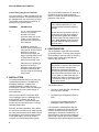
Control Port (3-way Screw Terminal)
The control port is a 3-way terminal block with
screwed connections. This terminal block can
be unplugged from the unit for ease of wiring.
The terminal connections are marked G, P
and M and are used as follows:
TERMINAL
CONNECTION
G
0V – It is recommended that
a wire is run from this
terminal to the main
protective earth point in the
system to give maximum
protection from interference
and transients.
P
In MANUAL mode, this
terminal can be pulled high to
select port B. In AUTO mode,
when PL41 is fitted, it
functions as an output and
will go logic high when port B
is being used or logic low
when port A is being used.
M
wire is connected between the ‘G’ terminal of
the SDS-122 and the system protective
ground, to ensure optimum internal transient
protection of the device.
CAUTION: Although the SDS-122 has
built-in transient protection, it is not
protected against secondary lightning
damage.
Devices that are connected to port A or
port B which are likely to be subject to
large transients should have external
protection fitted. For long cable runs on
port A, RAD-SRM Short Haul modems
fitted with RAD-SP lightning arrestors
should be used.
4. CONFIGURATION
The configuration of the SDS-122 is defined
by internal jumpers. To access these jumpers
it is necessary to open the case by removing
the four case screws and pulling the two
halves of the case apart.
When this line is pulled high,
the SDS-122 will be in
MANUAL mode and only the
port that is selected by the
user (by using the P terminal)
will be active.
CAUTION: Before touching any
components or jumpers, take precautions
against electrostatic damage when
handling the exposed circuit board –
either by using an ESD protection earth
strap connected to the sensor case, or, at
the very least, by making sure that you
discharge any static by touching the case
or metal shell of the 'D' type connectors
on the circuit board.
3. INSTALLATION
You should install the SDS-122 in a dry, noncondensing environment. The ENC12/14
datalogger enclosure, available from
Campbell Scientific, provides an ideal
environment for both a CR10/10X datalogger
and the SDS-122, plus a power supply or
other equipment.
Use one SC12 cable to connect the SDS122’s ‘datalogger’ port to a datalogger port,
and a second to connect port ‘B’ to a
compatible modem. A computer/short haul
modem can be connected to port ‘A’ using a
standard RS232 cable.
Normally, for most applications, there will be
no need for a connection to be made between
the 3-way terminal block on the SDS-122 and
the datalogger, unless direct measurements
of the switch status, or manual control is
required. It is recommended that a ground
4
The jumpers control:
•
The way in which the SDS-122 switches
from one port to another
•
The RS232 port configuration (DCE or
DTE)
•
The degree of isolation between the
datalogger and the RS232 device.
It is important to understand the different
methods of isolation, as this can affect the
accuracy of measurements made by the
datalogger. In permanent installations it is
good practice to ensure that the datalogger
ground and computer ground are isolated,
otherwise ground loops and digital noise could