1
CBI-1010 .
VAXBI SCSI Host Adapter
User's Manual
~IUI~CMD
s:
E TECHNOLOGr~~~~~
~/NC.
MAN-OOl01a-OOO
Rev. 1.3
June 1993
CBI-1010
VAXBI SCSI Host Adapter
User's Manual
CMD Technology, Inc.
1 Vanderbilt
Irvine, CA 92718
(714) 454-0800
Copyright
This manual is copyrighted and all rights are reserved. No portion of this document may be copied, photocopied, reproduced, translated, or reduced to any electronic medium or machine readable form without prior written consent from CMD Technology, Inc. (CMD).
CMD, CMD Technology, and CBI-1010 are all trademarks of CMD Technology, Inc. All other
product and company names are trademarks and registered trademarks of other manufacturers.
Copyright © CMD Technology, Inc. September 1991. All rights reserved.
Disclaimer
CMD reserves the right to make changes to this manual and the equipment described herein without notice. CMD has made all reasonable efforts to insure that the information in this manual is
accurate and complete. However, CMD shall not be liable for any technical or editorial errors or
omissions made herein or for incidental, special, or consequential damage of whatsoever nature
resulting from the furnishing of this manual, or operation and performance of equipment in connection with this manual.
FCC Notice
Class A Computing Device:
This equipment has been tested and found to comply with the limits for a Class A digital device
pursuant to Part 15 of the FCC Rules. These limits are designed to provide reasonable protection
against harmful interference when the equipment is operated in a commercial environment. This
equipment generates, uses, and can radiate radio frequency energy and, if not installed and used
in accordance with the instruction manual, may cause harmful interference to radio communications. Operation of this equipment in a residential area is likely to cause harmful interference in
which case the user will be required to correct the interference at his own expense.
Warranty
BASIC WARRANTY - In the absence of any optional warranty or continuing provisions by formal agreement, CMD warrants its products in accordance with the schedules listed below. Purchaser hereafter mentioned refers at all times to the customer who purchased CMD product(s).
HOST ADAPTER WARRANTY - CMD warrants Host Adapter products of its manufacture to be
free from defect in material and workmanship for a period of one year from the date of shipment.
During this period, if the customer experiences difficulties with a CMD Host Adapter and is unable to resolve the problem via phone with CMD Technical Support, a Return Material Authorization (RMA) will be issued. Following receipt of an RMA, the Purchaser is responsible for returning the product to CMD, freight prepaid. CMD, upon verification of warranty, will repair or replace at its option the Host Adapter in question, and will then return the product to the Purchaser, freight prepaid.
CABLE WARRANTY - All CMD provided cables are warranted for ninety (90) days from the
time of shipment. Questionable cables should be returned to CMD, freight prepaid, where they
will be repaired or replaced by CMD at its option and returned to the Purchaser, freight prepaid.
GENERAL TERMS - The above warranties shall not apply to expendable components such as
fuses, bulbs, and the like, nor to connectors, adapters, and other items not a part of the basic product. CMD shall have no obligation to make repairs or to cause replacement required through normal wear and tear or necessitated in whole or in part by catastrophe, fault or negligence of the
user, improper or unauthorized use of the product, or use of the product in such a manner for
which it was not designed, or by causes external to the product, such as, but not limited to,
power failure or air conditioning. CMD's sole obligation hereunder shall be to repair or replace
any defective product, and, unless stated, pay return transportation costs within the United States
of America for such replacement. Purchaser.shall provide labor for removal of the defective product, shipping charges for return to CMD and installation of its replacement. On-site services are
not a part of this warranty. Above warranties are subject to change without notice.
RETURNED MATERIAL - Warranty claims must be received by CMD within the applicable warranty period. A replaced product, or part thereof, shall become the property of CMD and shall
be returned to CMD at Purchaser's expense. All returned material must be accompanied by a Return Materials Authorization (RMA) number assigned by CMD. For RMA numbers call CMD at
(714) 454-0800.
THE EXPRESSED WARRANTIES SET FORTH IN THIS AGREEMENT ARE IN LIEU OF ALL
OTHER WARRANTIES, EXPRESSED OR IMPLIED, INCLUDING WITHOUT LIMITATION,
ANY WARRANTIES OF MERCHANTABILITY OR FITNESS FOR A PARTICULAR PURPOSE,
AND ALL SUCH OTHER WARRANTIES ARE HEREBY DISCLAIMED AND EXCLUDED BY
CMD. THESE STANDARD EXPRESS WARRANTIES ARE IN LIEU OF ALL OBLIGATIONS OR
LIABILITIES ON THE PART OF CMD FOR DAMAGES, INCLUDING BUT NOT LIMITED TO
SPECIAL, INDIRECT OR CONSEQUENTIAL DAMAGES ARISING OUT OF OR IN CONNECTION WITH THE USE OR PERFORMANCE OF THE PRODUCT.
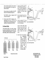
Return and
Repair Policy WARRANTY PERIOD
The following warranty period is from the date of shipment:
CMD Host Adapter
one year
Cable
90 days
Drive
manufacturer's warranty
RETURN FOR CREDIT
The allowable period of return for credit from the date of shipment is as follows
CMD Host Adapter
less than 30 days
Cable
less than 30 days
not applicable
Drive
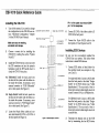
RETURN FOR REPAIR
CMD Host Adapter
In-Warranty (Less than 1 year)
• CMD offers a 15 working day turnaround repair seroice at the cost of parts only. Defective
boards will be repaired and returned to the customer within 15 working days from the
date of return to CMD.
• CMD also offers two in-warranty 24 hour expediting services:
24 Hour Turnaround Loaner Service:
Under this policy, CMD will ship a loaner in 24 hours during regular working days to the
customer for a charge of $100.00 per loaner. Upon receiving the loaner, customer must return the defective board to CMD within seven (7) days for repair. CMD will repair the defective board and return the board to the customer. Customer must then return the loaner
in seven (7) days after the receipt of the repaired board. Approval for loaner service is
based on credit verification.
24 Hour Turnaround Swap Service:
In the case that the defective board is within the first six (6) months of the warranty, CMD,
at its own option, offers a 24 hour turnaround swap service. CMD will ship the same
model of the board to customer within 24 hours during working days in exchange for the
defective board. CMD will swap with a new board if board is not functional upon arrival.
For all other cases, swap will occur with either a new or refurbished board for a charge of
$200.00. CMD does not offer swap services for boards that are purchased more than six
months from the date of shipment. Customer is responsible for returning the defective
board to CMD within seven (7) days after receipt of the swapped board.
• The remaining warranty period shall apply to the repaired or swapped board.
Out-of-Warranty (more than 1 year)
• CMD offers a 15 working day turnaround repair seroice at a rate of $300.00 plus parts and
freight for all out-of-warranty host adapter boards. Defective boards will be repaired and
returned to customer within 15 working days starting with date of return to CMD.
• CMD also offers an Out-of-Warranty 24 Hour Turnaround Loaner Service:
Under this policy, CMD will ship the same model loaner in the 24 hour time frame of working days to customer for an additional charge of $100.00 plus freight per loaner. The loaner
is for use by the customer during the period that the defective board is being repaired. Customer is responsible for returning the defective board to CMD within seven days after the
receipt of loaner and returning the loaner in seven (7) days once the defective board is repaired and received. The approval of the loaner service is at CMD's option and based upon
customer credit verification.
• CMD will extend warranty for a period of six (6) months on any out of- warranty repaired
board.
Cable
In-Warranty (90 days) - free swap.
Out-of-Warranty (90 days) - not applicable.
Drive
In-Warranty (per manufacturer) - manufacturer charge only.
Out-of-Warranty (per manufacturer) - manufacturer charge plus $100 CMD handling.
RETURN FOR UPGRADE/ UPDATE
CMD Host Adapter
In-Warranty (less than 1 year)
• CMD offers a 15 working day turnaround different function upgrade service for boards that can
be upgraded to a higher function; and a free 15 working day turnaround ECD Field Upgrade
for all its boards. CMD will upgrade the hardware of its board to a higher function for a
charge of the difference of list prices of the original and upgraded functions. CMD will
also update its board to its latest firmware release at no charge to the customer. Boards will
be upgraded/updated and returned to the customer within 15 working days from the date
of return to CMD.
• CMD also offers 24 hour turnaround loaner service as stated in "RETURN FOR REPAIR."
• The remaining warranty period shall apply to the updated board. For upgraded boards,
CMD will extend warranty for a period of six months.
Out-of-Warranty (More than 1 year)
• CMD offers a 15 working day turnaround different function upgrade service for boards that can
be upgraded to a higher function at a charge of the difference of list prices of two functions. CMD also offers a free 15 working day turnaround ECD Field Upgrade for all its boards.
Boards will be upgraded/updated and returned to customer within 15 working days from
the date of return to CMD.
• CMD also offers 24 hours turnaround Loaner Service as stated in "RETURN FOR REPAIR."
• There will be no warranty extension for same function firmware update. For different function Hardware upgrade, CMD will extend warranty for a period of six (6) months.
Drive-same as in RETURN FOR REPAIR.
SHIPPING CHARGES
The following shipping charges apply to all REPAIR, SWAP, LOANER, and UPGRADE UNITS.
In-Warranty
• Domestic - freight from CMD to customer is to be paid by CMD; freight from customer to
CMD is to be paid by customer.
• International- all fees are to be paid by customer (including custom duty and broker fees).
Out-of Warranty
• Domestic - all fees are to be paid by customer.
• International- all fees are to be paid by customer (including custom duty and broker fees).
GENERAL CONDITIONS
All goods returned to CMD including returns for credit, swap returns, loaner returns, and evaluation returns shall remain in good condition. Any damage or alteration done by the customer will
result in a rejection or additional charge to the customer.
Custom~r must consult CMD Technical Support for authorization of CMD not functional upon
arrival boards and swap requests. CMD Sales personnel must be consulted for authorization of
returned goods for credit and/ or evaluation.
Preface
Revision 1.3 of the CBI-IOIO manual contains the following changes from the
previous version:
• Instructions for switching between the CBI-IOIO/M and CBI-IOIO/MB
have been added to Chapter 3.
• An error in the ULTRIX Configuration section has been corrected. The
error was in steps 3 and 4 of the CBI-IOIO/TM instructions.
Preface
vii
viii
Preface
Table of Contents
1
Introduction
How to Use this Manual
Conventions
2
Features and Specifications
CBI-I0I0 Features
Special Features
Multi-Hosting
Tape Monitor Utility
Sync/ Async Mode
CBI-I0I0 Specifications
Cabling
Termination
3
Installation
Hard ware Configuration
Disk and Tape Emulation Selection for the CBI-I0I0/TM
Switching Between CBI-I0I0/M and CBI-I0I0/MB
System Node ID
Differential Mode
Single-Ended Mode
Installing the CBI-I0I0
SCSI Cabling
SCSI Terminator Power
SCSI ID for Host Adapter (Initiator)
CBI-I0I0 Installation Procedures
Installing SCSI Devices
1-1
1-1
1-2
2-1
2-1
2-3
2-3
2-4
2-4
2-5
2-6
2-6
3-1
3-1
3-2
3-3
3-4
3-6
3-8
3-9
3-9
3-10
3-10
3-10
3-14
Table of Contents
ix
Cable Specifications
SCSI ID for Target Devices
SCSI Device Installation Procedures
4
Setup
On-Board Utility
Accessing the Utility
Changing LUN Offset
Formatting the Drive
Qualifying the Drive
Manually Replacing Bad Sectors
Additional Utilities
Displaying SCSI Device and Setting Up Configuration
Sending SCSI Commands To The Device
Testing SCSI Device
Formatting RCT Block
Completing Utility Functions
Unit Numbering
Multi-Hosting Configuration
VMS Configuration
ULTRIX Configuration
CBI-I0I0/T
CBI-I0I0/M
CBI-I0I0/MB
CBI-I0I0/TM
5
SCSI Basics
SCSI Glossary
SCSI Commands
SCSI Status
SCSI Messages
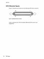
SCSI Single-Ended Signals
SCSI Differential Signals
A
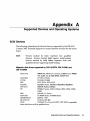
Supported Devices and Operating Systems
SCSI Devices
Magnetic disk drives supported
Erasable Optical disk drives supported
Erasable Optical disk cartridge manufacturers
x
Table of Contents
3-14
3-14
3-15
4-1
4-1
4-1
4-2
4-3
4-3
4-4
4-4
4-5
4-11
4-12
4-13
4-13
4-14
4-16
4-17
4-18
4-18
4-19
4-20
4-21
5-1
5-1
5-2
5-3
5-4
5-4
5-6
A-1
A-I
A-I
A-2
A-2
CD ROM disk drives supported
WORM drives supported
Tape drives supported
Jukeboxes supported
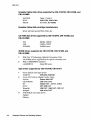
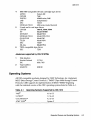
Operating Systems
B
Troubleshooting
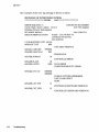
VMS Analyze/Error Utility
Cables
LED Indicators
CMD Technical Support
C Miscellaneous
Jumper Settings
A-2
A-2
A-2
A-3
A-3
B-1
B-1
B-3
B-3
B-4
C-1
C-1
Index
Quick Reference Guide
Table of Contents
xi
xii
Table of Contents
List of Figures
2
Features and Specifications
Figure 2-1: Front LED Assignment
2-2
3 Installation
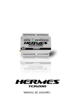
Figure 3-1: Components of the CBI-I0I0
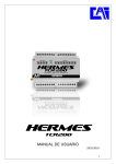
Figure 3-2: Jumper WI Pin Positions
Figure 3-3: Differential Card (CBI-I012) Installation
Figure 3-4: CBI-I012 Components
Figure 3-5: Single-Ended Card (CBI-I0ll) Installation
Figure 3-6: CBI-I0ll Components
Figure 3-7: Back Panel Cabling (Differential)
Figure 3-8: Back Panel Cabling (Single Ended)
Figure 3-9: Connectors on the system backplane
Figure 3-10: SCSI cabling
3-2
3-3
3-7
3-7
3-8
3-9
3-11
3-12
3-13
3-15
4 Setup
Figure 4-1:
Figure 4-2:
Figure 4-3:
Figure 4-4:
Figure 4-5:
Figure 4-6:
Figure 4-7:
Utility Main Menu
Utility Sub-menu
Current configuration, default
Configuration change
Synchronous transfer rate change
SCSI host adapter ID change
Disk and Tape Configuration Change
4-2
4-4
4-6
4-7
4-10
4-10
4-11
List of Figures
xiii
5
SCSI Basics
Figure 5-1: Single-Ended SCSI device connector
Figure 5-2: Differential SCSI device connector
C
Miscellaneous
Figure C-1: CBI-1010 jumper locations
Figure C-2: CBI-1010 Silk Screen Rev. C
xiv
5-4
5-6
List of Figures
C-3
C-4
List of Tables
2
Features and Specifications
Table 2-1:
Table 2-2:
Table 2-3:
Table 2-4:
Table 2-5:
3
Default Settings
WI Jumper S~ttings
CBI-I010/M and CBI-I0I0/MB Settings
Map of System Node ID for VAX 6000
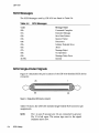
Connectors and Cables
Setup
Table 4-1: Default for Unit Numbers
5
2-2
2-3
2-3
2-5
2-6
3-1
Installation
Table 3-1:
Table 3-2:
Table 3-3:
Table 3-4:
Table 3-5:
4
CBI-I0I0 Models
LED Indicators
Special Feature Support List
Controller Specifications
Cable Specifications
2-1
SCSI Basics
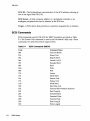
Table 5-1: SCSI Commands (MSCP)
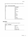
Table 5-2: SCSI Commands (TMSCP)
Table 5-3: SCSI Status
Table 5-4: SCSI Messages
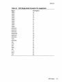
Table 5-5: SCSI Single-Ended Connector Pin Assignments
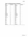
Table 5-6: SCSI Differential Connector Pin Assignments
3-1
3-3
3-4
3-5
3-9
4-1
4-14
5-1
5-2
5-3
5-3
5-4
5-5
5-7
List of Tables
xv
A Supported Devices and Operating Systems
Table A-I: Operating Systems Supported by CBI-IOIO
C
Miscellaneous
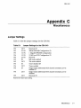
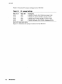
Table C-I: Jumper Settings for the CBI-IOIO·
Table C-2: WI Jumper Settings
xvi
List of Tables
A-1
A-3
C-1
C-I
C-2
1
Introduction
This User's Guide explains the basics of your CBI-lOlOTM. It includes
information on setting up and configuring the system and the CBI-lOlO
for use.
How to Use this Manual
This guide has five chapters and three appendices. Each chapter explains a
different aspect of preparing your CBI-lOlO for use. You may refer to the
appendices for further configuration and troubleshooting information. The
following descriptions summarize each section.
Chapter 1: Introduction explains the purpose of this guide and details the
conventions used.
Chapter 2: Features and Specifications describes the CBI-lOlO and details its
features and specifications.
Chapter 3: Installation describes hardware configuration and installation
procedures for the CBI-lOlO.
Chapter 4: Setup describes the On-Board Utility, set up of special features
and software configuration.
Chapter 5: SCSI Library lists a glossary on SCSI terms and gives SCSI status
and command codes for the CBI-lOlO.
Appendix A: Supported Devices and Host Computers lists the SCSI devices
and Host computers compatible with the CBI-lOlO.
Introduction
1-1
CBI-1010
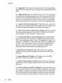
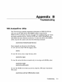
Appendix B: Troubleshooting gives some troubleshooting guidelines for the
CBI-IOIO under VMS®.
Appendix C: Jumper Settings list the jumper setting selections available on
the CBI-IOIO.
Conventions
The following conventions are used in the CBI-IOIO User's Guide.
Keycaps-Characters in square brackets represent keys on your keyboard. For
example, "Press [ENTER]" means press the [ENTER] key. When two or more
keys are joined by a plus sign (+), press those keys at the same time.
Commands-Italics text represents a command that can be used on a system,
eg., show dev duo
Entering Text or Commands on Screen-Text or commands that must be
entered on screen will be in italics and bold as show dev du; be sure to enter
the text or command and press [ENTER].
1-2
Introduction
2
Features and Specifications
This section briefly describes the CBI-I0I0 VAXBI SCSI Host Adapter and
details its specifications.
CBI-1010 Features
The CBI-I0I0 is an intelligent high performance VAXBI SCSI host adapter that
is fully compatible with the DEC Mass Storage Control Protocol (MSCP) and
Tape Mass Storage Control Protocol (TMSCP). Each CBI-I0I0 is fully licensed
by Digital and is built around DEC's own BIIC interface chip.
The CBI-I0I0 can be used with the 5800, 6000, 8000, and 9000 series VAXBI
systems. It supports VMS, ULTRIX, and selected UNIX operating systems
which use DU!TU drivers.
The CBI-I0I0 supports either a single-ended or differential SCSI channel. A
single-ended SCSI channel can be used for connecting up to 9.9 feet of cable
(when the transfer rate is 10 MBytes/second) while a differential SCSI channel
can be used to connect up to 80 feet of cable.
The CBI-I0I0 features Octaword DMA master transfers, virtual data buffer,
command queuing, dynamic defect management, standard SCSI bus
arbitration, disconnect and reconnect capabilities, and multiple host
capability. Up to seven SCSI devices (either single-ended or differential) can
be connected to the CBI-I0I0 SCSI port with SCSI bus data transfer rate up to
10-MB/sec in synchronous (sync) mode and 7-MB/sec in asynchronous
(async) mode.
Features and Specifications
2-1
CBI-1010
The CBl-1010 supports a variety of sync/ Async SCSI devices including
magnetic disk, tape, and optical disk drives. Table 2-1 lists the devices
supported by the different CBl-1010 models.
CB\-1 01 o· Models
Tab\e 2-1
CBI-l0l0/ M
CBI-l0l0/ T
CBI-l0l0I™
CBI-l0l0 1MB
supports disk drives only
oUSly
supports tape drives only
supports disk and tape drives simultallE
supports disk drives only
The CBI-1010 has an On-Board Utility for yOU to format and configure the
SCSI drives, scan bad blocks and replace them automaticallY, and test SCSI
disk and tape drives.
The CBI-101
an on-board non-volatile RAM (NoVRAM-) to store the
0haS
drive Logical
Unit Number Offset and other important information to handle
configuration of devices.
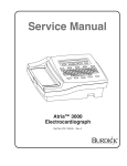
The CBI-1010 features six LEos--three green, one red, and twO yellOW. These
LEDs are visible from the front or top of the chassis when the system is
running and are labeled as shown in Figure 2-1.
YELLOW
0998
ent
fIgure 2-1: front LEO Ass\gnrn
2-2
Features and specificatiOns
CBI-1010
Table 2-2 describes the conditions of CBI-IOIO when LED's are lit.
Table 2-2
LED Indicators
LED
. DS1-Right
DS1-Left
Color
red
green
DS2-Left
green
DS2-Right
green
D998/
D999
yellow
Indication
Error condition occurred.
Power-up OK and activity indicator. Upon power up, this
LED lights when the CQD-220 succeeds in the selfdiagnostic testing. During normal operation, this LED will
blink to show controller activity.
SCSI controller chip Single-ended mode enabled when lit.
Differential mode enabled with not lit.
Terminator power pin is supplied with power. Refer to
Figure 3-1.
Self-test passed.
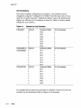
Special Features
The CBI-IOIO supports special features that pertain to the different CBI-IOIO
models as listed Table 2-3.
Table 2-3
Special Feature Support List
Model
CBI-1010/TM
CBI-1010/T
CBI-1010/M
CBI-1010 1MB
Multi-Hosting
Yes
Yes
Yes
Yes
TMU
Yes
Yes
No
No
Multi-Hosting
CBI-IOIO gives you the ability to completely share an array of disks and tapes
between multiple VAX systems running VAX cluster software. CMD's
multi-host solution can support disk, tape, and optical devices including jukeboxes. Multi-hosting instructions are given in Chapter 4, under
Additional Utilities." Refer to Appendix A for supported disk and tape
devices. Refer to Chapter 4 for configuration instructions.
II
Features and Specifications
2-3
CBI-1010
Tape Monitor Utility
The Tape Monitor UtilityTM (TMU) is an application software developed by
CMD Teclmology and work exclusively with CMD SCSI host adapters as an
optional feature for VAX/VMS systems.
This Tape Monitor UtilityTM runs under VMS and displays the tape drive vendor identification, drive firmware revision, the remaining tape capacity, percentage of rewrites during writes or percentage of ECC retrys during reads,
and current tape operations such as read, write, write file mark, space, rewind, etc. You can install multiple CBI-IOIOs and tape drives in one site and
observe all tape activity from any VAX terminal locally or across the network
without any additional add-in hardware. You also can open a file to log all
the information during unattended backup.
To install the Tape Monitor Utility, use On-Board Utility (Chapter 4,
subsection Additional Utilities") to enable TMU since the factory setting for
TMU OFF. Then follow the instructions given in the accompanying CMD Tape
Monitor Utility User's Manual part number MAN-OOOTMU-OOl.
1/
SynclAsync Mode
The CBI-IOIO comes standard in synchronous mode. Most SCSI devices
support synchronous mode. However, you can change the CBI-IOIO to
asynchronous mode using the On-Board Utility in Chapter 4.
In Sync mode, CBI-IOIO will automatically negotiate with each SCSI
device connected to find out whether the Sync mode is supported by the
device.
In Async mode, CBI-IOIO will communicate with the SCSI device
asynchronously even if the SCSI device supports Sync mode. Most of the
Sync SCSI devices also support Async mode.
2-4
Features and Specifications
CBI-1010
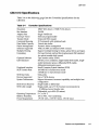
CBI-1 01 0 Specifications
Table 2-4 on the following page lists the Controller Specifications for the
CBI-IOIO.
Table 2-4
Controller Specifications
Emulation
Bus Interface
Adapter Size
Interrupt Vector
Transfer Mode
Command Queuing
Data Buffer Capacity
Defect Management:
Software Supported
Multiple-Hosting
Formatting
Optional Software
LED Indicators
Peripheral Interface
SCSI Transfer Rate
SCSI Bus Parity
Devices Supported
System Performance
SCSI Driver/Receiver
SCSI Cable Length
Operating Temperature
Relative Humidity
Power Requirement
MSCP (DU driver) / TMSCP (TU driver)
VAXBI
Single VAXBI slot
Software programmable
Octaword DMA master
32 Commands with optimized seek
Virtual data buffer
Dynamic defect management
VMS, ULTRIX and selected UNIX versions
Support multiple-hosting for disks, optical drives and tapes.
On board format and bad block replacement (ISO standard
for optical erasable disk format)
Tape monitor utility (TMU)
Self test, error conditions, single-ended SCSI enable, singleended terminator power, differential SCSI enable,
differential terminator power
Small Computer System Interface (SCSI)
10.0-MB/sec in Synchronous mode
7.0-MB/sec in Asynchronous mode
Odd parity
Up to 7 SCSI devices
Support disconnect/reconnect capability and multiple host
configuration
Single-ended or differential
Single-ended, up to 9.9 ft (3 meters) recommended at
10 MBytes / second transfer rate
Differential, up to 80 ft (25 meters)
5° C to 50° C
10% to 900/0 , Non-condensing
+5V DC 6.0A, +12V DC 14mA, -12V DC 6mA
Features and Specifications
2-5
CBI-1010
Cabling
The CBI-1010 will operate in single-ended or differential mode; however,
CMD Technology strongly recommends the use of differential mode when the
data transfer rate exceeds five megabytes per second. If you have no choice
but to use single-ended mode at a high transfer rate, the SCSI-3 proposal recommends that the total internal and external cable length should be no longer
than three (3) meters or 9.9 feet when the transfer rate is 10 MBytes/second.
Furthermore, the single-ended cable should meet or exceed the following
specifications.
Table 2-5
Cable Specifications
Characteristic Impedance
No less than 90 ohms and no greater than 140
ohms
Signal Attenuation
.095 dB maximum per meter at 5 MHz
Pair-to-pair Propagation
Delay Delta
.15 nanoseconds maximum per meter
DC Resistance
.23 ohms maximum per meter at 20 degrees C
Termination
The single-ended daughter card adapter for the CBI-1010 employs active termination. Some SCSI devices still use passive termination, which is inadequate at high transfer rates. If your system is running in single-ended mode at
transfer rates in excess of five megabytes per second and the CBI-1010 is at
one end of the SCSI bus, you must use active termination or some other type
of high-performance termination at the other end of the bus.
2-6
Features and Specifications
3
Installation
This chapter details hardware configuration and installation for the CBI-1010.
The CBI-1010 must be configured first, installed in the system second, and
SCSI devices installed last. This chapter is organized in the order the CBI-1010
must be installed; after completing hardware installation, refer to "Setup" in
Chapter 4. Features not selectable here can be selected through the On-Board
Utility in Chapter 4.
Hardware Configuration
This section details setting up various features for the CBI-1010 before installing it inside a system. Be sure to follow the instructions listed in each subsection for proper configuration. Table 3-1 illustrates the default settings for each
CBI-1010 model.
Table 3-1
Model
CBI-IOIO/TM
CBI-IOIO/T
CBI-IOIO/M
CBI-IOIO/MB
Default Settings
Wl(1-3)
Wl(2-4)
W5(1-2)
OUT
OUT
OUT
OUT
OUT
OUT
OUT
OUT
OUT
OUT
OUT
IN
U9
PAL PIK08
PAL PIK28
PALPIK29
PAL PIK58A
Note that (F) means factory setting.
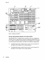
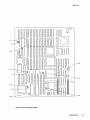
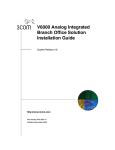
Figure 3-1 illustrates the components on the CBI-1010.
Installation
3-1
CBI-tOtO
CPU
U9
--~~ DID~fmml..'
'---~ 1
(
__ (::::::::::3
~_-_~
- (:::::::3 -
1
(:::::::3(::::::::::1
(:::::::3
~
3
1"---_.(,_ _ _"II~-~
1
4
~
I
J
....---.. ~::=::::{ IDI:::::::::::.:~ :::::::::::::~:::::::~ ~:::::::~
'---_--' (:::::::3
.::::::::::::3 C:::::::::::I:::::::3 (:::::::3
1:::::::::::3 (:::::::3~~1~:::~:::~::~::~::3~~~~~~~~~
1:::::::::::3
'---- ..._-.,............... (:::::::3
~
(:::::::3
~c: J D"
C:::::::3
< (:::::::3
I IIII I D
--1.:::m!ll!!lIIIl111mDJ ~---,<r=~1
,
(::::::::3 (:::::::3 (:::::::3 (:::::::J
~
<
VUlt
CHIP
c::J c::J c:::::>
D
(:::::::3 (:::::::3 C:::::J C::::::::::3 C:::::3
C3
q~W8::J
(:: :::::< '--------'
JE
Figure 3·1: Components of the CBI·1 01 0
Disk and Tape Emulation Selection for the CBI-1 01 O/TM
The CBI-IOIO/TM is a multiple function controller. When you configure the
CBI-IOIO/TM as a single function controller (configured through RS-232 Utility as 0 disk or 0 tape) the unused function must be disabled. You can disable
one of the functions shown below, see Table 3-2 for different configurations.
3-2
•
To disable tape function, install a shunt on pins I and 3 of jumper WI.
See Figure 3-2 for location of WI and pin positions.
•
To disable disk function, install a shunt on pins 2 and 4 of jumper WI.
See Figure 3-2 for location of WI and pin positions.
Installation
CBI-1010
Table 3-2
W1 Jumper Settings
Pins 1 & 3
Pins 2 & 4
OUT
OUT
IN
OUT
OUT
IN
Description
CBI-IOIO/TM with PAL PIK08 in location U9 (F)
CBI-IOIO/TM configured for disk only with PAL PIK08
in location U9
CBI-IOIO/TM configured for tape only with PAL PIK08
in location U9
Note that (F) means factory setting.
::S[@ C::::::::J 1::::::::::: 3
:::3- [:::::: ::JI:::: ::: ::J 1::::::::::: 3
0
1
:::::
::3 I: ::: :: ::: :: 51: : : : : : : : : J
I:::::::::J
Figure 3·2: Jumper W1 Pin Positions
Switching Between CBI-1010/M and CBI-1010/MB
Both the CBI-lOlO/M and CBI-lOlO/MB support disk drives only, but the CBI1010/M offers KLESI emulation, while the CBI-lOlO /MB offers KDB50 emulation, which is necessary for bootability on VAX 6000 systems. Switching between the CBI-lOlO/M and CBI-IOIO/MB models is a simple matter of changing the PAL at location U9 and either removing or installing the jumper at
WS. All CBI-IOIO/M adapters come with PAL PIK29 installed at U9 and PAL
PIK58A as an accessory. Likewise, all CBI-IOIO/MB adapters come with PAL
PIK58A installed at U9 and PAL PIK29 as an accessory.
Be sure to turn off power to the adapter before you switch the PAL at U9. Use
a screwdriver to pry the PAL loose and then remove it with your fingers. In-
Installation
3-3
CBI-1010
sert the alternative PAL and press down until it is fully seated. Make sure
that the alignment of the notch at one end of the PAL is identical to the surrounding chips. This will assure a proper pin-one match. Before restoring
power, change the jumper at W5 to the appropriate setting for the model you
desire. Table 3-3 shows the EPROM and jumper settings for each model.
Table 3-3
CBI-1 01 OIM and CBI-1 01 O/MB Settings
Model
CBI-IOIO/M
CBI-IOIO/MB
Emulation
KLESI
KDB50
W5
OUT
IN
U9
PAL PIK29 installed
PAL PIK58A installed
System Node 10
Care must be taken when installing a CBI-I0I0 to avoid having the operating
system change the physical device names of the currently installed devices.
During auto configure, each device found is given a unique device name. The
device names are expressed as:
ddcu
where
dd = type of device (Le. MU,DU,PT,PU)
c = Controller designator (A,B,C ... )
u = Unit number
The device name is determined by the physical address of the controllers port
registers OP /SA). Since these addresses are fixed within the CBI-I0I0, there
are no concerns with configuring the device type. Refer to Chapter 4, Table
4-1 for unit numbers.
The controller designator is derived by the operating system as it scans I/O
space. The first MSCP disk controller found is given the letter' A', the second
MSCP disk controller 'B' and so on. This will generate devices DUAx/PUAx,
DUBx/PUBx, incrementing the controller letter until all disk controllers are
found. The same is true for each TMSCP tape controller, yielding devices
MUAx/PTAx, MUBx/PTBx and so on.
The scan will start at node 0 and will work its way up to the last node ID
within the system. On native BI systems (Le. 8200/8250/8350), the node ID of
the BI is the system node ID. In these systems, the system ID's range from
o to 15.
3-4
Installation
CBI-1010
On systems where the BI is the system I/O bus (i.e. 58xx, 85xx, 8700, 8800 and
aIl6000's), the system node ID does not match the BI node ID. For example, a
VAX 6000 machine has 240 system node ID's. The XMI bus has 15 nodes each
logically capable of containing a bus adapter with 16 node ID of its own.
Physically this arrangement is not permissible, however, this is how VMS
looks at the system.
Table 3-4 shows a map of system node ID's for a VAX 6000 type machine.
Table 3-4
Map of System Node 10 for VAX 6000
XMI node
1
2
3
4
5
System nodes
0-15
16 - 31
32 - 47
48 - 63
64 - 79
80 - 95
96 - 111
112 - 127
128 - 143
144 - 159
160 - 175
176 - 191
192 - 207
208 - 223
224 - 239
6
7
8
9
10
11
12
13
14
15
It is desirable to install the CBI-I0I0 at a system node ID that will not change
the physical device names of the currently installed devices. This is
accomplished by installing the CBI-l0l0 at a higher system node ID than
any other currently installed device of the same type.
The CBI-I0I0/T is device type PT /MU and should be installed at a higher
system node ID than other TMSCP tape controllers. The CBI-I010 /M and CBI1010/MB is a device type PU/DU and should be installed at a higher system
node ID than other MSCP disk controllers. The CBI-I0I0/TM is a device type
of PU /DU and PT /MU and should be installed at a higher system node ID
than other MSCP disk and TMSCP tape controllers.
Installation
3-5
CBI-1010
If you do not adhere to these guidelines, currently installed devices that have
a higher system node ID than the CBI-lOlO will have their controller designator changed (incremented by the number of CBI-lOlO's installed).
As an example, if the current system has a KDB-50 disk controller installed at
XMI node IS, BI node 4, (system node ID 228) and a CBI-lOlO/M,
CBI-lOlO/TM or CBI-lOlO/MB installed at XMI node 14, BI node 4, (system
node ID 212), the controller designator for the KDB-50 will be incremented
from' A'to 'B' and the CBI-lOlO will have the controller designator of 'A'.
Differential Mode
The CBI-lOlO supports either single-ended or differential SCSI modes. The
CBI-lOlO SCSI port is factory configured to your specifications. If for any reason you need to convert the CBI-lOlO from single-ended SCSI mode to differential, follow these instructions.
NOTE
3-6
Use only the components supplied by CMD.
1
Remove the single-ended SCSI daughter card (CBI-lOll) from the lower
left comer of the CBI-lOlO board.
2
Install the differential SCSI daughter card (CBI-1012) at the same location of the CBI-lOlO board. Make sure to align Jl of the daughter card
with Jl of the CBI-lOlO board. See figure 3-3.
Installation
CBI-tOtO
J1
J2
Figure 3-3: Differential Card (CBI-1012) Installation
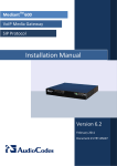
Figure 3-4 illustrates the components of the CBI-I012 differential daughter
card. The terminator resistors are located at U22 and U23.
I
RN1
II RN2
I
0000000000000000000000000 Jl
0000000000000000000000000
8~~ CID
~
~@]
~ @J
~
00
~
~
[§J
~ [ill
~
I~I CTID~(~)Sff~
u~
@J
~
Q
~~
~ T.r ~
@]cm
~Cill@]
00 00
[(;l)Ta(~)
00
Lfu
OOOOOOOOO~
OOOOOOOOO:S
~
00000000000
0000000000000
00000000000
0000000000000
O~~ 0 0 0 0 0 0 0 J2 000 0 000 OU030
~
@J
~
~
~
:J
~~
@(gQ)
I"
.
I
C21
.
Figure 3-4: CBI-1 012 Components
Installation
3-7
CBI-1010
Single-Ended Mode
The CBI-I0I0 is factory configured to user specifications. However, if you
need to convert the CBI-I0I0 from differential to single-ended, follow these
instructions.
1
Remove the differential SCSI daughter card (CBI-I012) from the lower
left comer of the CBI-I0I0 board.
2
Install the single-ended SCSI daughter card (CBI-I0ll) at the same location of the CBI-I0I0 board. Make sure to align Jl of the daughter card
with Jl of the CBI-I0I0 board. See figure 3-5.
J1
J2
Figure 3-5: Single-Ended Card (CBI-1 011) Installation
Figure 3-6 illustrates the components of the CBI-I0ll single-ended daughter
card. The terminator resistors are located at RNI and RN2.
3-8
Installation
CBI-1010
Jl
0000000000000000000000000
0000000000000000000000000
RNl
~--------------~
(
C2
RN2
)
J2
0000000000000000000000000
0000000000000000000000000
Figure 3-6: CBI-1011 Components
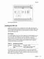
Installing the CBI-1 01 0
Installing the CBI-IOIO involves installing the board, cables, terminating the
SCSI bus, identifying and testing SCSI devices with the On-Board Utility. This
section explains these topics prior to listing installation procedures; carefully
read the explanations first.
SCSI Cabling
The VAXBI systems provide two 30-pin connectors in the backplane for every
one of the VAXBI Zero Insertion Force (ZIF) connectors JC, JD, and JE. The
30-pin connector on the component side of the CBI-IOIO is defined as
connector CONI. The 30-pin connector on the solder side of the CBI-IOIO is
defined as connector CON2 (see Figure 3-4 for details). Table 3-5 lists the
connectors and cables for the CBI-IOIO.
Table 3-5
Connectors and Cables
Connector
Connector - CONl
Single-Ended/Differential
signals
JE
Connector - CON2
On-Board RS-232 Utility & SingleEnded/Differential signals
The CBI-IOIO comes with one three-foot SCSI I/O cable (including RS-232
utility interface) and system back panel adapter kit. The I/O cable is a 60-conductor cable. One end has two 30-pin connectors and the other end has 50-pin
SCSI connector and a IO-pin connector.
Installation
3-9
CBI-1010
CMD strongly recommends the use of differential mode
in systems employing transfer rates in excess of five
megabytes per second. If you have no alternative but to
use single-ended mode, the SCSI-3 proposal recommends that the total length of the SCSI cable be no
longer than three meters (about 9.9 feet) at 10 megabytes
per second. See page 2-6 for more details.
NOTE
SCSI Terminator Power
Typically the initiator (SCSI host adapter) supplies terminator power,
+5-volts, to the SCSI bus. Because the CBI-lOlO is considered an initiator to
the SCSI devices, the terminator power option of the CBI-lOlO needs to be
enabled.
The CBI-lOlO supplies terminator power to the TERMPWR pins of singleended/ differential SCSI connector (JE) through a polyswitch and jumper
block, WB. (Check Tables 5-5 and 5-6 for pin assignments.)
SCSI 10 for Host Adapter (Initiator)
Each device on the SCSI bus requires a unique SCSI Identification address
(0 to 7). SCSI ID 7 has the highest priority on the bus and SCSI ID a has the
lowest priority.
The CBI-lOlO plays the role of initiator and is factory configured to SCSI ID 7.
To alter the Host Adapter SCSI ID, change NOVRAM settings through the
On-Board RS-232 Utility given in Chapter 4.
CBI-1 010 Installation Procedures
1
Make sure the system is powered OFF. Make sure the CBI-IOIO is
configured as given in the section, "Hardware Configuration."
WARNING
3-10
Make sure you are wearing anti-static wrist straps.
2
Choose a correct slot for installing the CBI-lOlO by reading the section
"System Node ID."
3
Install the CBI-lOlO in the correct slot with the ZIF connectors set into
the system's backplane; push the ZIF handle down to clamp the
CBI-IOlO into place.
Installation
CBI-tOtO
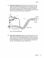
48
Differential Configuration: Install the back panel into the back of the
system with the ribbon cable inside the system. If necessary, move the
external connector to the "SCSI Differential" slot on the back panel by
unscrewing the connector from the "SCSI Single Ended" slot and the
plate from the "SCSI Differential" slot. Swap the plate and the connector
and screw them both back into place. (See Figure 3-7.)
JE CON1
JE CON2
Ribbon Cable
SCSI Differential Slot
Figure 3-7: Back Panel Cabling (Differential)
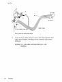
4b
Single Ended Configuration: Install the back panel into the back of the
system with the ribbon cable inside the system. If necessary, move the
external connector to the "SCSI Single Ended" slot on the back panel by
unscrewing the connector from the "SCSI Differential" slot and the plate
from the "SCSI Single Ended" slot. Swap the plate and the connector
and screw them both back into place. (See Figure 3-8.)
Installation
3-11
CBI-1D10
JE CON1
JE CON2
Ribbon Cable
Figure 3·8: Back Panel Cabling (Single Ended)
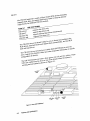
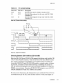
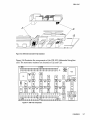
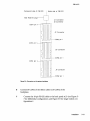
5
Locate the 60-pin ribbon cable and connect cable labeled JE CONI to JE
CONI of the backplane. (See Figure 3-9 for connectors on the system
backplane.)
WARNING Pin 1 of the cable must match CONi pin 1 of the
backplane.
3-12
Installation
CBI-tOtO
Component side of CBI-lOl 0
Solder side of CBI- 101 0
Blue Node ID plug----l
JA Connector
JB Connector
CONl pin
• • • •
• • • •
• •
• •
• •
• •
• •
• •
• •
• •
• •
• •
CONl pin
CONl pin
•
•
•
•
•
•
•
•
•
•
•
•
•
•
JC Connector
•
•
•
•
•
•
•
e-+---+--CON2 pin
• • •• ••
• • • •
• • • •
• •
• • •• ••
• • • •
JD Connector
• • • •
• • • •
• • •
• • •
• • • •
• • • •
• • • •
e-+---+--CON2 pin
• •
' - - _ - - - 1 .•- _ - - '
• • •
• •
• •
• • •
• • •
• • •
• •
• • ••
• • •
• •
• • •
• • ••
• • •
• • •
• •
•
•
•
•
•
•
•
•
•
•
•
•
•
JE Connector
•~__+_- CON2
L..-...J.._ _-'----_-1-.....J
pin
Figure 3·9: Connectors on the system backplane
6
7
Connect JE CON2 of the ribbon cable to JE CON2 of the
backplane.
Connect the IO-pin RS-232 cable to the back panel at JI (see Figure 37 for differential configurations and Figure 3-8 for single ended configurations.)
Installation
3-13
CBI-1010
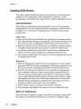
Installing SCSI Devices
This section details installing devices from the connectors of the back panel
adapter kit to the SCSI devices~ Read carefully the subsections, "Cable
Specifications" and "SCSI ID for Target Devices" before installing the devices.
Cable Specifications
Single-ended and differential cable specifications vary; see the appropriate
paragraph below for cable specifications before attempting to install devices.
See page 2-6 for a discussion of cabling issues in systems running at high
transfer rates.
Single-ended:
• When the CBI-IOIO and the SCSI devices are installed in the same cabinet
that meets EMI/RFI shielding requirements, a 25-conductor twisted pair cable must be used for connecting the CBI-IOIO (JE) and the SCSI devices.
• When the CBI-IOIO and the SCSI devices are installed in separate cabinets,
a shielded twisted pair cable must be used to meet FCC requirements.
• A minimum conductor size of 2S-AWG must be used to minimize noise
effects and ensure proper distribution of optional terminator power.
• The maximum cable length is 3.0 meters or 9.9 feet in single-ended mode at
10 megabytes per second.
Differential:
• When the CBI-IOIO and the SCSI devices are installed in the same cabinet
that meets EMI/RFI shielding requirements, a 25-conductor twisted pair cable must be used for connecting the CBI-IOIO (JE) and the SCSI devices.
• When the CBI-IOIO and the SCSI devices are installed in separated cabinets, a shielded twisted pair cable must be used to connect the SCSI devices from the back panel adapter kit meeting FCC requirements. Otherwise, crosstalk between adjacent signals causing spurious pulses on differential signals will occurs even at slow data transfer rates and short cable
distances. Each pair should be connected to the same signal, one wire to
the positive signal, and the other wire to the negative.
• Cables should consist of conductors of 26-AWG or 2S-AWG.
• The maximum cable length is 25 meters or SO feet in differential mode.
SCSI 10 for Target Devices
Each SCSI device (initiator or target) on the SCSI bus requires a unique SCSI
ID number. Since the CBI-IOIO has been set to SCSI ID 7 (initiator), target
3-14
Installation
CBI-1010
devices must be set from SCSI ID 0 to 6. Normally, the assignment of SCSI
Target ID starts with SCSI ID 0 on single function boards.
The factory setting of the CBI-I0I0/TM is four disk devices (SCSI ID=O to 3)
and three tape devices (SCSI ID=4 to 6). If you have more than four disks
drives or three tapes drives you must use the On-Board Utility to change the
configuration; if you do not, you do not need to change the configuration.
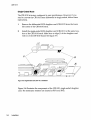
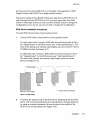
SCSI Device Installation Procedures
To install SCSI devices follow the procedures below:
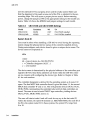
1
Connect SCSI cables as listed below for the specified mode:
For single-ended mode: Connect a SCSI cable from the back panel at the label "Single-Ended" to the SCSI devices (see "Cable Specifications"). The
total of the internal and external cable lengths must not exceed 9.9 feet at
10 MBytes/ second. See Figure 3-10.
For differential mode: Connect a SCSI cable from the back panel at the label "Singled-Ended" to the SCSI devices (see "Cable Specifications").
The total of the internal·and external cable lengths must not exceed
80 feet. See Figure 3-10.
SCSI Bus Cable
SCSIID=7
SCSIID=2 T
T
SCSI
Device
CBI-1010 in Host Computer
SCSI
Device
SCSI
Device
T indicates SCSI bus termination.
Figure 3·10: SCSI cabling
2
Terminate the physical ends of the SCSI bus by terminating the last SCSI
device with on-board termination (see manufacturer's documentation) or
by using an external terminator. Be sure devices in the middle of the
SCSI bus are not terminated (see Figure 3-10).
Installation
3-15
CBI-1010
The CBI-IOIO is factory configured with on-board termination.
3
NOTE
3-16
Installation
Set the devices SCSI ID numbers to the specifications set forth in "SCSI
ID for Target Devices" (see manufacturer's documentation for setting
devices SCSI ID).
For multi-hosting refer to section, "Multi-Hosting
Configuration."
4
Setup
This chapter will assist you in setting up the CBI-IOIO and your system
for use.
On-Board Utility
The CBI-IOIO SCSI host adapter comes with the general purpose RS-232 utility for all DEC VAXBI systems. The On-Board utility can test the VAXBI slot,
SCSI cable, and SCSI devices connected to the CBI-IOIO. Be sure to complete
utility functions, explained at the end of this chapter.
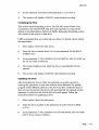
Accessing the Utility
To access the RS-232 utility, follow the instructions below.
1
Connect a terminal to the CBI-1010's RS-232 port (DB-25 connector or
DEC compatible RJ-11/Modified Module 423 Jack connector of the back
panel adapter kit).
2
Set the terminal baud rate to 9600 (8-bit data, I-stop bit, no parity).
Setup
4-1
CBI-1010
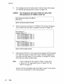
3
Halt the system's CPU, reset the system, and hit carriage return on the
terminal. The main menu will display as shown in Figure 4-1 on the
following page.
SCSI HOST ADAPTER UTILITY (REV. YYYXZZ)
x = EXIT
[DISK]
[TAPE]
1 = LOGICAL UNIT NUMBER OFFSET
6 = LOGICAL UNIT NUMBER OFFSET
2 = FORMAT DRIVE
7 = ADDITIONAL UTILITIES
3 = QUALI FY DRIVE
4 = MANUALLY REPLACE BAD BLOCKS
5 = ADDITONAL UTILITIES
SELECT OPTION ?
Figure 4-1: Utility Main Menu
Once the main utility menu shows up, you can key in the number to
select the desired option. Press [CTRL] + C at any time to return to the
main menu.
4
Refer the the next subsections for configurations. When completed,
unplug the terminal, reset the system, and boot. DO NOT use the OnBoard Utility while the system is running.
Changing LUN Offset
When a system has a HSC or in a VAX cluster it will be necessary to
change the LUN (Logical Unit Number) offset. Each MSCP drive requires a
different Unit Number so that the unit numbers are not duplicated. If there
are no other MSCP controllers in the system, the LUN offset can be o.
If there exists another MSCP controller with four drives (0 to 3), then the LUN
offset should be four or above. In the case that LUN offset is equal to 10, SCSI
ID 0 will be DUBIO and SCSI ID 1 will be DUB1l. The drives will show up as
such DUAO, DUAl, DUA2, DUA3, DUBIO, DUB11 (see section, "SCSI ID for
Target Drives" in Chapter 3 for explanation).
4-2
Setup
1
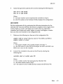
Select option 1 from the main menu for disk drives; 6 for tape drives.
2
Enter the new value for LUN offset at the statement: PRESENT LUN
OFFSET = 0, ENTER NEW VALUE:
CBI-1010
3
At the statement: SAVE NEW CONFIGURATION (Y or N)? enter Y.
4
The monitor will display
COMPLETE
when finished executing.
Formatting the Drive
This section details formatting a drive. The CBI-IOIO issues Format Unit
Command to the selected SCSI disk drive and requests it to map out the
defects on the Manufacture Defect List (MDL). Remember formatting a drive
will rewrite all the sectors of that drive.
CMD recommends that you format all new drives. To format a drive, follow
the steps below:
1
Select option 2 from the main menu.
2
Enter the device number from 0 to 6 in the statement:
ENTER DEVICE
NUMBER 0 TO 6 :
3
At the statement: *** WILL DESTROY DATA ON DEVICE X, ARE YOU SURE? enter Y if you want to continue.
4
The monitor displays WAIT while the drive is executing the format
process.
5
The monitor will display
COMPLETE when
finished executing.
Qualifying the Drive
After formatting the device, CMD recommends you qualify devices by
running this procedure at lease once without errors detected. The qualify
program writes different patterns to the drive and then verifies the data. If
there are any bad sectors, the sectors will automatically be replaced and the
statement XX XXXXXXXX BAD BLOCK REPLACED will appear. Follow the
instructions below for qualifying a drive.
1
Select option 3 from the main menu.
2
Enter the device number at the statement:
QUALIFY DEVICE NUMBER
<0 TO 6>:
3
At the statement: *** WILL DESTROY DATA ON THIS DEVICE, ARE YOU SURE?
enter Y if you want to continue.
Setup
4-3
CBI-1010
4
The monitor will display QUALIFY STARTED <SEQUENTIAL WRITE AND
READ>! <HIT <BREAK> TO ABORT>.
5
The monitor will display TESTING LOOP COUNT AND BLOCK NUMBER:
6
Press [BREAK] to exit back to the main menu after you are satisfied with
the qualifying process.
Manually Replacing Bad Sectors
This option allows you to replace bad sectors manually. The controller
supports dynamic defect management which replaces defective sectors on-line
so there is no need to manually replace bad sectors. However, if you wish to
replace bad sectors manually follow these instructions; remember that any
data in the sector will be lost:
1
Select option 4 from the main menu.
2
Enter the device number at the statement: DEVICE NUMBER? DEV <0 TO 6>:
3
Enter the logical block number in HEX at the statement: ENTER THE BAD
BLOCK NUMBER <HEX>:
4
The monitor will display -BAD BLOCK REPLACED- when finished
executing.
Additional Utilities
To access additional utilities for disk drives, select option 5 from the main
menu. To access additional utilities for tape drives, select option 7 from the
main menu. The additional utilities menu will display as shown in Figure 4-2.
ADDITIONAL UTILITIES
(REV. YVYxZ2.)
SN
= 1278X
D = DISPLAY SCSI DEVICE AND SET UP CONFIGURATION
S = SEND SCSI COMMAND TO THE DEVICE
T = TEST SCSI DEVICE
R = FORMAT RCT BLOCK
SELECT OPTION?
Figure 4-2: Utility Sub-menu
4-4
Setup
CBI·1010
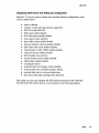
Displaying SCSI Device and Setting Up Configuration
Selection 'D' can be used to change the controller default configurations such
as those listed below:
• reset to default
• number of disk and tape devices supported
• SCSI ID of the CBI-IOIO
• SCSI reset enable / disable
• SCSI disconnect enable/ disable
• sync/async mode selection
• tape buffer mode enable/ disable
• prevent medium removal enable/disable
• disk write with verify enable/disable
• Tape Monitor Utility (TMU) enable/disable
• Tape Fast Search enable/disable
• SCSI transfer rate selection
• remote density mode enable/disable
• default tape enable/disable
• reconfigure device
• autoboot start from floppy enable/disable
• write protect from controller jumper setting
• truncate disk size for volume shadowing
• eject removable disk cartridge after dismount
This utility can also scan/display the SCSI devices attached to the CBI-IOIO.
The CBI-IOIO/TM will be shown as an example in the following display.
Setup
4-5
CBI-1010
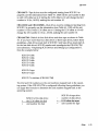
To display SCSI devices and set up configuration follow the procedures below.
Select option D at the sub-menu (Figure 4-2), the following current
configuration is displayed as shown in Figure 4-3.
1
DEVO
DUO, SCSI ID 0, LUN 0
Disconnect ON, Sync Mode ON, Prevent Medium Removal ON, Write WNerity OFF
DEV1
DU1, SCSI ID 1, LUN 0
Disconnect ON, Sync Mode ON, Prevent Medium Removal ON, Write WNerity OFF
DEV2
DU2, SCSI ID 2, LUN 0
Disconnect ON, Sync Mode ON, Prevent Medium Removal ON, Write WNerity OFF
DEV3
DU3, SCSIID 3, LUN 0
Disconnect ON, Sync Mode ON, Prevent Medium Removal ON, Write WNerity OFF
DEV4
MUO, SCSI ID 4, LUN 0
Disconnect ON, Sync Mode ON, Prevent Medium Removal ON, Buffer Mode ON
DEV5
MU1, SCSI ID 5, LUN 0
Disconnect ON, Sync Mode ON, Prevent Medium Removal ON, Buffer Mode ON
DEV6
MU2, SCSI ID 6, LUN 0
Disconnect ON, Sync Mode ON, Prevent Medium Removal ON, Buffer Mode ON
DEV7
SCSI ID 7, HOST ADAPTER SCSI Reset ON, Tmu OFF, Fast Search OFF, sync rate=4mb, Density Mode ON, Default Tape OFF Boot Floppy OFF, Jumper Write Protect OFF,
Eject Disk ON, Truncate Size OFF, Rsv/Rls Option ON, Sel Timeout=250 msec
Figure 4-3: Current configuration, default
NOTE
2
NOTE
4-6
Setup
If Truncate Size is toggled, IITruncate Mode ON" will
display under each disk device options and at the bottom when configuration is displayed.
To change the configuration, enter Y at the statement: CHANGE
CONFIGURATION? (YIN). The menu shown in Figure 4-4 will display.
See subsection, IIUnit Numbering" before trying to reconfigure devices.
CBI-1010
R = Toggle SCSI Reset
M = Toggle Density Mode
B = Toggle BufferlTruncate Mode (Tape/Disk)
D = Toggle Disconnect
S = Toggle Sync/Async
W = Toggle DensitylWrite Verify Mode (Tape/Disk)
P Toggle Prevent Medium Removal (Disk only)
C = Reconfigure Device
F Toggle Fast File Search(Tape only)
Q =ToggieTMU
U = Toggle Default Tape (Tape Only)
G = Toggle FMT
A = Autoboot Start From Floppy Drive
N = Write Protect from Controller Jumper Setting
V = Truncate Disk Size for Volume Shadowing
E = Eject Disk after Dismount
L = Reserve/Release Disk Option
J = Change Selection Timeout Period
T = Reset All Device Modes to Default
Z = Reset Controller to Default Configurtation
(Hit <return> key to exit)
=
=
Figure 4-4: Configuration change
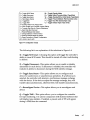
The following list is an explanation of the selections in Figure 4-4.
R = Toggle SCSI reset-Choosing this option will toggle the controller's
ability to issue SCSI resets. This should be turned off when multi-hosting
is desired.
D = Toggle Disconnect-This option allows you to enable or disable
disconnect for each device. If disconnect is enabled, the controller will
indicate its ability to disconnect during the SCSI identify message.
S = Toggle SyndAsync-This option allows you to configure each
device for synchronous or asynchronous operations. If synchronous is
selected, the controller will attempt a synchronous message exchange
with the device. If the device accepts the message exchange, they will
transfer data synchronously, otherwise they will transfer asynchronously.
C = Reconfigure Device-This option allows you to reconfigure each
device.
Q = Toggle TMU-This option allows you to configure the controller
for tape monitoring. It is used in conjunction with licensed software that
will display tape statistics. If enabled, a pseudo unit of 255 will appear
during a VMS show dev command.
Setup
4-7
CBI-tOtO
G = Toggle FMT-This options enables DU254 to show up for SCSIformat ON-LINE. This feature must be enabled when using SCSIformat ONLINE.
U = Toggle Default Tape-This option allows you to force the presence
of a tape unit to the operating system even if one does not exist. This is
needed for some operating systems when the controller is connected to
devices with a long self test procedure after power-up. If it is disabled,
only units connected to the controller are seen by the operating system.
A = Autoboot Start From Floppy Drive-This option allows you to set
the system to boot directly from the first floppy drive; if no floppy drive
is present, the system will begin to boot from the first device.
N = Write Protect from Controller Jumper Setting-This option may be
used when jumper setting for front panel is IN to allow you to select
write protection to disk 0 and disk 1. Default is OFF.
v
= Truncate Disk Size for Volume Shadowing-This option allows
the size of the disk to be truncated to multiples of 126 blocks to allow
VMS volume shadowing copy process to reach higher performance. The
message "** WARNING ** Truncate Size ON/OFF will be toggled, Are
you sure?" will display before truncate switch can be toggled. If this
feature is used on a disk that contains valid data, the data must be
removed and later restored after turning this feature ON.
E = Eject Disk after Dismount-This option allows you to specify
whether the removable disk cartridges will eject from the drive after
dismount.
L = Reserve/Release Disk Option-This option is to let the MSCP
ON-LINE exclusive use modifier to be operable.
. T = Reset all Devices Mode to Default-These modes are-disconnect,
synchronous, Prevent Medium Removal, Write with Verify, and Buffer
modes, etc.
Z = Reset Controller to Default Configuration-This option allows the
user to set the controller to its factory default configuration. This will set
the controller to support four disk drives, three tape drives; disconnect,
SCSI reset, synchronous communication, buffer mode, prevent medium
removal and density selection enabled; and fast file search, write with
4-8
Setup
CBI-1010
verify, write protect disabled, reserve/release disabled, and default tape
disabled. ALWAYS use this feature before reconfiguring the board.
M = Toggle Density Mode-This option allows you to configure the
controller for remote density selection. If enabled, remote density
selection may take place. If enabled, the controller reports itself as a
'TU81'. If disabled, it reports itself as a 'TKSO'.
B = Toggle Buffer/Truncate Mode (Tape/Disk)-For tape devices, this
option allows the controller to configure each individual tape device for
write caching. If enabled, the tape device will send command complete
message and good status to the controller once the data as been transferred to the tape device's internal buffers. If disabled, such message and
status will be sent when the data is actually written to the tape. For disk
devices, you may toggle truncate disk size, see "V = Truncate Disk Size
for Volume Shadowing" for explanation.
W = Toggle Write WNerify-This option will allow the SCSI command
Write with Verify to be issued for MSCP write with verify modifier.
When set to OFF (which is the default), the normal write command will
be issued.
P = Prevent Medium Removal-This option is for removable disk
drives only. When set to ON, a "Prevent Medium Removal" will be
issued to a drive when it is mounted by VMS. This will disable the eject
media push-button in front of the drive. An Allow Medium Removal"
will be issued when the drive is dismounted by VMS and the pushbutton will be enabled. This features can be disabled and the media can
be ejected at anytime.
1/
F = Toggle Fast File Search-This option allows you to configure the
controller for normal or fast file searching. The difference between
normal and fast file search is the type of SCSI commands used to find
file marks. A normal file search will issue iterative 'Space Record'
commands until a file mark is encountered, while the fast mode will issue a single 'Space filemark' command. VMS may use Fast File Search
mode if you do not attempt a stand-alone boot or run other programs
that require· the controller to keep track of the number of objects. In VMS
stand-alone boot applications, this option needs to be disabled. When
fast file mark is enable, the controller's ability to keep correct position
information for the host is not possible.
Setup
4-9
CBI-1010
3
To reconfigure the device select option C and the screen will prompt
you with the following question as shown in Figure 4-5.
WARNING
Use homogeneous high quality twisted pair cables within
SCSI specifications for 5-MB/sec transfer rate.
Enter Synchronous transfer rate (MB/sec)
Enter (4-10)
Figure 4-5: Synchronous transfer rate change
4
Enter synchronous rate from 4 to 10 MB/sec. The screen will prompt
you to answer the next series of questions as shown in Figure 4-6.
Enter Initiator ID 7
4
Number of Disks? (0-7)
DUO to be Reconfigured ?
DU1 to be Reconfigured?
DU2 to be Reconfigured?
DU3 to be Reconfigured?
(YIN)
(YIN)
(YIN)
(YIN)
N
N
N
N
Number of Tapes? (0-3)
3
MUO to be Reconfigured? (YIN)
MU1 to be Reconfigured? (YIN)
MU2 to be Reconfigured? (YIN)
N
N
N
Figure 4-6: SCSI host adapter 10 change
5
NOTE
Enter Initiator SCSI ID 7 or the required Host Adapter SCSI ID (default
is 7). Enter the number of disk and/or tapes. Default configuration is
four disks, and three tapes; it is not necessary to configure if running
fewer than four disks and three tapes.
If zero is selected for the number of disk or tapes, place
a shunt over the appropriate pins on jumper WI. See
Table 3-2 on page 3-3.
Answer Y or N to reconfigure each of the disks or tapes. If you answer
Y, the screen will prompt you with these questions:
4-10
Setup
CBI-1010
(DUX SCSI ID? <0-7>
J
~_D_U_X_L_U_N_?_<_O-_3_>______________________________________
Figure 4-7: Disk and Tape Configuration Change
NOTE
6
This LUN is SCSI LUN; it is normally O. This is used
only for devices that support multiple LUN's.
When you have completed these instructions the display will show your
current configuration and prompt you again with the question CHANGE.
CONFIGURATION? (YIN). Enter N; this will cause the CBI-lOlO to scan the
SCSI bus.
The utility will display your current configuration with manufacturer's
name, model number, and firmware revisions for each device.
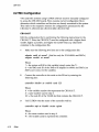
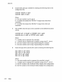
Sending SCSI Commands To The Device
Selection'S' can be used to send SCSI commands to the selected disk/tape
drives directly.
This option is used to send a 6-, 10-, or l2-byte command to a SCSI device.
Follow these procedures to send SCSI commands to the device:
1
Enter S from the "Additional Utilities" Menu. (Be sure you have correctly selected either 5 from the Main Menu for disk drives, or 7 for tape
drives.)
2
At the question DEVICE NUMBER? DEV <0-6> enter the device number.
3
Enter the command sequence at the statement:
READY TO TEST DEVICE X
EDIT CDB <HEX> ***<ESC> TO TERMINATE EDITING***
BYTE 0000=
00
If a 6- or la-byte command is used, press [ESC] to terminate command
editing. If a l2-byte command is used, command editing is terminated
automatically.
Setup
4-11
CBI-1010
4
At the statement WRITE DATA TO THE DEVICE? <Y OR N> enter N to
immediately send the command if SCSI command does not require a
data out phase.
Or enter Y to send data to the device after the command phase if SCSI
command requires a data out phase. Enter the data and enter [ESC] to
terminate editing. The statement SAVE EDITED DATA IN BUFFER?
<Y OR N> will appear. Enter Y to save data in the buffer; or enter N to
erase edited data after the command is sent.
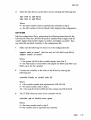
Testing SCSI Device
Selection 'T' can be used to read only, write and read selected disk drive,
and/or write and read selected tape drive continuously. This is a diagnostic
tool to help with installation and testing. Follow the procedures below to test
the SCSI device.
1
Enter T from the Additional Utilities" menu. (Be sure you have
correctly selected either 5 from the main menu for disk drives, or 7 for
tape drives.)
2
At the question DEVICE NUMBER? DEV <0-6> enter the device number.
3
When testing for disk devices, at the statement READY TO TEST THE DEVICE
DO YOU WANT TO READ ONLY? <Y OR N> enter Y to read only or N to
read and write. If you selected N, the question ARE YOU SURE? will
display. Enter Y to read and write to the device.
/I
WARNING
Nwill destroy all data on the device.
When testing for tape devices, the statement ARE YOU SURE? will display.
Enter Y to test the device.
4
4-12
Setup
The test will continue until you abort. Allow the test to continue for a
few minutes' for new devices and ten minutes for suspected bad devices.
Press [BREAK] or [CTRL] + C to abort and exit back to the main menu.
CBI-1010
Formatting ReT Block
Selection 'R' can be used to format the RCT blocks of the disk drive selected.
This command writes zeros in the last logical block of the device. If you try to
skip the formatting process and directly use the drive, you must use this
option to eliminate "unrecoverable bad RCT block." However, CMD
recommends you format the drive. To format the RCT block follow these
instructions:
1
Select R from the Additional Utilities" menu. (Be sure you have
correctly selected either 5 from the main menu for disk drives, or 7 for
tape drives.)
2
Select the device number at the statement:
3
FORMAT COMPLETE
II
DEVICE NUMBER DEV <0-6>.
will display when RCT block has been formatted.
Completing Utility Functions
The following procedures should be done when using the On-Board Utility.
1
Use the On-Board Utility to verify the VAXBI slot seating, SCSI cable,
and SCSI devices connected to the CBI-IOIO after installing the CBI-IOIO
in the VAXBI slot.
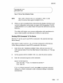
2
After verifying the SCSI connections, disconnect RS-232 cable from the
back panel, and reset the system; make sure that the system scans this
VAXBI node (where the CBI-IOIO is installed) successfully. The
following indicators will display when the system completes the scan:
•
•
•
NOTE
A negative sign (-) of the VAXBI node ID displayed in the system
terminal indicates that the scanning of that VAXBI slot is
unsuccessful. When this condition occurs, reseat the CBI-IOIO in the
VAXBI slot or use a different VAXBI slot and repeat the installation
procedures.
A period (.) signifies nothing is found in that slot. Follow the
procedures given for the negative sign if an adapter is in that slot.
A positive sign (+) or the node ID number signifies the system found the
CBI-IOIO and the node passed the self test.
If the terminal is connected, this may cause the OnBoard Utility to be invoked during system operation and
will take control of the Host Adapter from VMS.
Setup
4-13
CBI-1010
Unit Numbering
This section explains configuring unit numbers. Unit numbers may be
changed by using the "Configure LUN Offset" from the main menu. If you
used the 'D' option from the "Additional Utilities" menu, the terminal will
display the MU and/ or DU numbers as shown in Table 4-1, factory default
settings for unit numbers.
Table 4-1
Default for Unit Numbers
CBI-IOlorr
SCSIID
0
1
CBI-IOIO/M or
CBI-IOIOIMB
2
3
4
S
6
SCSIID
0
1
2
3
4
S
CBI-IOIOrrM
6
SCSIID
0
1
2
3
4
S
6
On-Board Utility
MUO
MUI
MU2
MU3
MU4
MUS
MU6
On-Board Utility
DUO
DUI
DU2
DU3
DU4
DUS
DU6
On-Board Utility
DUO
DUI
DU2
DU3
MUO
MUI
MU2
OS Unit Number
0
1
2
3
4
S
6
OS Unit Number
0
1
2
3
4
5
6
OS Unit Number
0
1
2
3
0
1
2
An example below is given for each type of controller to show how the unit
numbers can be determined. Refer to Figure 4-3 if necessary.
4-14
Setup
CBI-1010
CBI-1010ff-Tape drives must be configured starting from SCSI ID 0 to
properly use the information from Table 4-1. MUO will be unit number 0; this
is with LUN offset set to o. Setting the LUN offset to 10 will change·the MU
number to 10 (ie., MU10), making the unit number 10.
CBI-1010/M and CBI-1010/MB-Disk drives must be configured starting from
SCSI ID 0 to properly use the information from Table 4-1. DUO will be· unit
number o. This is with LUN offset set to o. Setting the LUN offset to 10 will
change the DU number to 10 (ie., DU10), making the unit number 10.
CBI-1010ffM-Default is four disk drives and three tape as shown in Table
4-1. If you have more than four disk drives or three tape drives, follow these
guidelines-disk drives must start at SCSI ID 0 and tape drives must start after the last disk drive's SCSI ID number and reconfigure the CBI-1010/TM
(see subsection, "Displaying SCSI Devices and Setting Up Configuration").
Note the example below:
SCSI ID 0 disk
SCSI ID 1 disk
SCSI ID 2 disk
SCSI ID 3 disk
SCSI ID 4 disk
SCSI ID 5 tape
SCSI ID 6 tape
SCSI ID 7 is inititaor (CBI-I010/TM)
The MU and DU numbers are the unit numbers mapped back to the operating system. If the CBI-1010/TM is configured following these guidelines, you
can apply this formula to determine the unit number mapped back to the
operating system:
+
=
SCSI ID of the disk drive
the LIJN offset for djsk
unit number for disk
+
=
SCSI ID of tape drive
number of disk drives
LUN offset for tapes
unit number for tape
Setup
4-15
CBI-tOtO
Multi-Hosting Configuration
The following is a list of software requirements for multi-hosting:
•
•
•
•
VMS version 5.3 or above
VAX cluster software must be running on both systems with at least
one of the DEC's interconnects operational
Tape drives can only be mounted to one system at a time
Allocation classes must be the same for all systems when installing
disk drives (value must not equal 0).
Refer to Appendix A for supported multi-hosting devices and follow the
instructions below for multi-hosting:
1
From the Additional Utilities Menu in the On-Board Utility, follow these
instructions:
a
b
c
d
e
f
9
h
NOTE
4-16
Setup
Select option D to display current configuration.
Answer Y to the statement: CHANGE CONFIGURATION? (YIN) The
menu shown in Figure 4-4 will display.
Select R to toggle SCSI reset.
Set the host adapter SCSI reset to OFF. Do this for all SCSI host
adapters to be multi-hosted.
Answer Y to reconfigure the adapter.
Select C to reconfigure the device.
Configure the CBI-IOIO to SCSI ID 7 for the first computer, and SCSI
ID 6 for the second computer.
Configure the CBI-IOIO for exact number of disks and tapes. This
will inhibit scanning of other host adapters (see Figure 4-6).
If other MSCP disks are in the cluster, follow the rules in the
subsection "Changing LUN Offset" in liOn-Board Utility" so that
each device has a unique unit number.
In a multi-hosting system the physical disk device name
must be identical on both systems.
CBI-1010
2
Terminate both physical ends of the SCSI bus.
If the CBI-IOIO is at either end of the SCSI bus, do not change the
configuration. The CBI-IOIO is factory configured with on-board
termination.
If the CBI-IOIO is in the middle of the SCSI bus, terminators must be
removed from the default setting as listed below:
For single-ended mode: remove RNI and RN2 from daughter card
(CBI-IOII). See Figure 3-6 on page 3-8.
For differential mode: remove U22 and U23 from daughter card
(CBI-IOI2). See Figure 3-4 on page 3-7.
In the event that one system becomes inoperable with only two nodes in the
VAX cluster, a quorum disk must be used to count as a vote; this keeps the
other system running. Refer to VMS VAXcluster manual order number
AA-LA27A-TE to set up a quorum disk and a VAX cluster.
NOTE
When running cluster_config.com on a system with only
Ethernet as a computer interconnect, answer Yes for the
question, "WILL THIS BE A SATELLITE NODE?"
VMS Configuration
VAX systems using VMS software will automatically configure new devices
added. NO other configuration is required if guidelines are followed from
Chapter 3, "System Node ID."
Setup
4-17
CBI-1010
ULTRIX Configuration
VAX and DEC systems using UL TRIX software must be manually configured
to access the CBI-lOlO boards. First, examine current configuration file to
determine which controllers and devices are already connected to the system.
Then refer to the respective sections for configuration procedures for the
CBI-lOlO/T, CBI-lOlO/M, CBI-lOlO/MB, CBI-lOlO/TM.
CBI-1 01
orr
Edit the configuration file by performing the following instructions for the
CBI-lOlO/T. Note, th~ CBI-lOlO/T must be configured with a higher klesib
number, higher uq number, and higher tms number than any otherklesib
controller in the configuration file.
1
Make sure the following two lines are in the configuration file:
adapter xmiO at nexus? (this line only for VAX 6000's and 58l0's)
adapter vaxbi& at nexus?
Where
? = the system will fill in this variable (simply enter this ?).
& = the XMI node ID of the XMI to BI adapter for 6000's and 58l0's (on
8200's use 0, zero, for the variable).
2
Connect the controller to the node on the BI bus by entering the
following line:
controller klesibf} at vaxbi& node XX
Where
f} = the variable number that represents the CBI-lOlO/T.
& = same number used in step 1.
XX = the node ID of the VAXBI slot that contains the CBI-lOlO/T.
3
Tell ULTRIX what the name of the controller will be:
controller uq# at klesibf} vector uqintr
Where
f} = the same number used in step 2.
# = the variable used to represent the controller.
4-18
Setup
CBI-1010
4
Name the tape drives and list drive unit by entering the following line:
tape tmsO at uq# driven
tape tmsl at uq# driven
Where
# = the same number used to represent the controller in step 3.
n = the MU number in the On-Board Utility displays this configuration.
CBI-1010/M
Edit the configuration file by performing the following instructions for the
CBI-lOlO/M. Note the CBI-lOlO/M must be installed with a higher node ID
number, higher klesib number, higher ra number, and higher uq number than
any other kdb and klesib controller in the configuration file.
1
Make sure the following two lines are in the configuration file:
adapter xmiO at nexus? (this line only for VAX 6000's and 58l0's)
adapter vaxbi& at nexus?
Where
? = the system will fill in this variable (simply enter this ?).
& = the XMI node ID of the XMI to BI adapter for 6000's and 58l0's (on
8200' s use 0, for the variable).
2
Connect the controller to the node on the BI bus by entering the
following line:
controller klesibf} at vaxbi& node XX
Where
f} = the variable number that represents the CBI-lOlO/M.
& = the same number used in step 1.
XX = the node ID of the VAXBI slot that contains the CBI-lOlO/M.
3
Tell ULTRIX what the name of the controller will be:
controller uq# at klesibf} vector uqintr
Where
f} = the same number used in step 2.
# = the variable used to represent the controller.
Setup
4-19
CBI-1010
4
Name the tape drives and list drive unit by entering the following line:
disk raO at uq# driveJ3
disk ral at uq# driveJ3
Where
# = the same number used to represent the controller in step 3.
J3 = the DU number in the On-Board Utility displays this configuration.
CBI-1 01 O/MB
Edit the configuration file by performing the following instructions for the
CB1-1010/MB. Note the CB1-1010/MB must be installed with a higher node ID
number, higher kdb number, and higher ra number than any other kdb controller
in the configuration file.
1
Make sure the following two lines are in the configuration file:
adapter xmiO at nexus? (this line only for VAX 6000's and 5810's)
adapter vaxbi& at nexus?
Where
? = the system will fill in this variable (simply enter this ?).
& = the XM1 node 1D of the XM1 to B1 adapter for 6000's and 5810's (on
8200's use 0 for the variable).
2
Connect the controller to the node on the B1 bus by entering the
following line:
controller kdb1} at vaxbi& node XX
Where
1} = the variable number that represents the CB1-IOIO/MB.
& = the same number used in step 1.
XX = the node 1D of the VAXB1 slot that contains the CB1-I010/MB.
3
Tell ULTRIX what the name of the controller will be:
controller uq# at kdb1} vector uqintr
Where
1} = the same number used in step 2.
# = the variable used to represent the controller.
4-20
Setup
CBI-tOtO
4
Name the tape drives and list drive unit by entering the following line:
disk raO at uq#
disk ral at uq#
drive~
drive~
Where
# = the same number used to represent the controller in step 3.
~ = the DU number in the On-Board Utility displays this configuration.
CBI-1 01 O/TM
Edit the configuration file by performing the following instructions for the
CBI-1010/TM. Note the CBI-I010/TM must be configured with a higher klesiu
number, higher uq number, and higher tms numbers than any other klesiu
controller; and a higher uda number, higher uq number, and higher ra number
than any other uba controller in the configuration file.
1
Make sure the following two lines are in the configuration file:
adapter xmiO at nexus? (this line only for VAX 6000's and 5810's)
adapter vaxbi& at nexus?
Where
? = the system will fill in this variable (simply enter this? ).
& = the XMI node ID of the XMI to BI adapter for 6000's and 5810's (on
8200's use 0, zero, for the variable).
2
Connect the controller to the node on the BI bus by entering the
following line:
controller ubat1 at vaxbi& node XX
Where
t1 = the variable number that represents the CBI-1010 /TM.
& = the same number used in step 1.
XX = the node ID of the VAXBI slot that contains the CBI-1010/TM.
Setup
4-21
CBI-tOtO
3
Connect disk and tape controller by entering the following lines in the
configuration file:
controller klesiu# at ubat}
controller uda$ at ubat}
Where
t} = the same number used in step 2.
# = a number that makes the CBI-IOIO/T unique from other klesiu
controllers.
$ = a number that makes the CBI-IOIO/T unique from other uda
controllers.
4
Tell ULTRIX what the name of the controller for the different functions
will be:
controller uqV at klesiu# csr 0174500 vector uqintr
controller uqfl. at uda$ csr 0172150 vector uqintr
Where
V = variable used to represent the controller.
fl. = variable used to represent the controller (unique from V above).
# = the same number used in step 3 representing the controller.
$ = the same number used in step 3 representing the controller.
5
Name the tape drives and list drive unit by entering the following line:
tape
tape
disk
disk
tmsO at uqV drivea
tmsl at uqV drivea
raO at uqfl. drive~
ral at uqfl. drive~
Where
V = the same number used to represent the controller in step 4.
fl. = variable used to represent the controller (unique from V above).
a = the MU number in the On-Board Utility displays this configuration.
~ = the DU number in the On-Board Utility displays this configuration.
4-22
Setup
5
SCSI Basics
This chapter consists of a SCSI glossary, SCSI commands used by the
CBI-IOIO for MSCP emulation, SCSI status codes, SCSI messages, SCSI
single-ended and differential signals.
SCSI Glossary
The following is a glossary of frequently used SCSI terms.
Connect-The function that occurs when an initiator selects a target to start
an operation.
Disconnect-The function that occurs when a target release control of the
SCSI bus, allowing it to go to the BUS FREE phase.
Initiator-A SCSI device (usually a host system) that requests an operation to
be performed by another SCSI device.
LUN-Logic Unit Number.
Peripheral device-A peripheral that can be attached to a SCSI device (e.g.,
magnetic disk, magnetic tape, or optical disk).
Reconnect -The function that occurs when a target selects an initiator to
continue an operation after a disconnect.
SCSI address-The octal representation of the unique address (0-7) assigned
to an SCSI device. This address would normally be assigned and set in the
SCSI device during system installation.
SCSI Library
5-1
CBI-1010
SCSI ID-The bit-significant representation of the SCSI address referring to
one of the signal lines DB (7-0).
SCSI device-A host computer adapter or a peripheral controller or an
intelligent peripheral that can be attached to the SCSI bus.
Target-A SCSI device that performs an operation requested by an initiator.
SCSI Commands
SCSI commands used by CBI-1010 for MSCP emulation are listed in Table
5-1. The Format Unit command is used by the On-Board Utility only. These
commands are used if the drives support them.
Table 5-1
Code
Command Name
OOh
Test Unit Ready
Rezero Unit
Request Sense
Format Unit (l)
Reassign Block
Read
Write
Seek
Inquiry
Mode Select
Reserve Unit
Release Unit
Mode Sense
Start/Stop Unit
Prevent/ Allow Medium Removal
Read Capacity
Extended Read
Extended Write
Extended Seek
Read Long (2)
Write Long(2)
01h
03h
04h
07h
08h
OAh
OBh
12h
15h
16h
17h
1Ah
1Bh
1Eh
25h
28h
2Ah
2Bh
3Eh
3Fh
5-2
SCSI Commands (MSCP)
SCSI Library
CBI-1010
SCSI commands used by CBI-IOIO for TMSCP emulation are listed in Table
5-2.
Table 5-2
SCSI Commands (TMSCP)
Code
OOh
Olh
03h
08h
OAh
IOh
Ilh
12h
ISh
16h
I7h
I9h
lAh
IBh
IEh
Command Name
Test Unit Ready
Rewind
Request Sense
Read
Write
Write Filemarks
Space
Inquiry
Mode Select
Reserve Unit
Release Unit
Erase
Mode Sense
Load/Unload
Prevent/ Allow Medium Removal
SCSI Status
The SCSI status codes used by CBI-IOIO are listed in Table 5-3.
Table 5-3
Code
OOh
02h
08h
IOh
I8h
SCSI Status
Status Name
Good
Check Condition
Busy
Intermediate/Good
Reservation Conflict
SCSI Library
5-3
CBI-tOtO
SCSI Messages·
The SCSI Messages used by CBI-1010 are listed in Table 5-4.
Table 5-4
SCSI Messages
Code
Message Name
OOh
OIh
Command Complete
Extended Message
Save Data Pointer
Restore Pointer
Disconnect
Initiator Detected Error
Abort
Message Reject
No Operation
Message Parity Error
Identify
02h
03h
04h
OSh
06h
07h
08h
09h
80-FFh
SCSI Single-Ended Signals
Figure 5-1 illustrates the pin locations of the CBI-1010 shielded SCSI device
connector.
25
50
26
Figure 5-1: Single-Ended SCSI device connector
Table 5-5 shows the CBI-IOIO shielded single-ended SCSI connector pin
assignments.
NOTE
5-4
SCSI Library
Pin 1 to pin 25 (except pin 13) are connected to ground.
Pin 13 is left open. The minus sign next to the signal
indicates active low.
CBI-tOto
Table 5-5
SCSI Single-Ended Connector Pin Assignments
Signal
Pin Number
-DB(O)
26
-DB(1)
27
-DB(2)
28
-DB(3)
29
-DB (4)
30
-DB (5)
31
-DB (6)
32
-DB(7)
33
-DB(P)
34
GROUND
GROUND
GROUND
35
36
37
TERMPWR
38
GROUND
GROUND
39
-ATN
41
GROUND
42
-BSY
43
-ACK
-RST
-MSG
-SEL
44
45
46
47
-C/D
48
-REQ
49
-I/O
50
~
SCSI Library
5-5
CBI-1010
SCSI Differential Signals
Figure 5-2 illustrates pin locations for the differential SCSI device connector.
25
50
26
Figure 5-2: DlfferenUal SCSI device connector
Table 5-6 illustrates the CBI-IOIO shielded differential SCSI connector pin
assignments.
5-6
SCSI Library
CBI-1010
Table 5-6
SCSI Differential Connector Pin Assignments
Signal
Pin Number
Signal
Pin Number
GROUND
+DB(O)
+DB(1)
+DB (2)
+DB(3)
+DB(4)
+DB (5)
+DB(6)
+DB(7)
+DB(P)
DIFFSENS
GROUND
TERMPWR
GROUND
+ATN
GROUND
+BSY
+ACK
+RST
+MSG
+SEL
+C/D
+REQ
+1/0
GROUND
1
2
3
4
5
6
7
8
9
10
11
12
13
14
15
16
17
18
19
20
21
22
23
24
25
GROUND
-DB(O)
-DB(1)
-DB(2)
-DB(3)
-DB (4)
-DB(5)
-DB(6)
-DB(7)
-DB(P)
GROUND
GROUND
TERMPWR
GROUND
-ATN
GROUND
-BSY
-ACK
-RST
-MSG
-SEL
-C/D
-REQ
-I/O
GROUND
26
27
28
29
30
31
32
33
34
35
36
37
38
39
40
41
42
43
44
45
46
47
48
49
50
SCSI Library
5-7
CBI-1010
5-8
SCSI Library
Appendix A
Supported Devices and Operating Systems
SCSI Devices
The following subsections list devices that are supported by the CBI-IOIO.
Contact CMD Technical Support for correct firmware revision for the drives
listed.
NOTE
Devices marked by italics represent new qualified
devices; devices marked bold support multi-hosting;
devices marked by bold italics represent both new
qualified devices supporting multi-hosting.
Magnetic disk drives supported by CBI-1010ITM, CBI-1010/M, and
CBI-1010/MB
SEAGATE
WREN VI, SWIFT (3-1/2-inch), SABRE 8-inch, WREN
VII, ELITE I & II (5400 RPM), WREN VIII
CONNER
CP-3100, CP3200
CITOH
YD-3042, YD3082
DEC
RZ23, RZ24, RZ56, RZ57
M2246SA Series, M2249SA, M2263SA, M2266SA
FUJITSU
HITACHI
DK515C Series, DK516C
HP
97548S/D series, C2233, C2234, C2235, C3010, C3009,
C3007
mM
320-MB,3-1/2-inch
XT -4oo0S Series, XT-800OS Series
MAXTOR
MICROPOLIS
1588-15 , 1598
QUANTUM
ProDrive 4OS/80S
TEAC
FD235HS (3-1/2-inch FLOPPY, DEC RX23 compatible)
More disk drives will be qualified soon.
Supported Devices and Operating Systems
A-1
CBI-1010
Erasable Optical disk drives supported by CBI-1010ITM, CBI-1010/M, and
CBI-1 01 O/M B
MAXTOR
SONY
RICOR
Tahiti 1, Tahiti 2
SMO-0501, SMO-0502
RO-5030E, RO-5030E2
Erasable Optical disk cartridge manufacturers
SONY, RICOR, MAXOPTICS, PIX), 3M.
CD ROM disk drives supported by CBI-1010ITM, CBI-1010/M, and
CBI-1 01 O/MB
DEC
LMS
TOSHIBA
RRD40 , RRD42
CM210, CM212
XM3200 series
WORM drives supported by CBI-1010ITM, CBI-1010/M, and
CBI-1 01 O/M B
1
With Ten X Technology Optical Conversion Unit
All WORM drives supported by the optical conversion unit.
2
With LASERDRIVE interface
LASERDRIVE
Model 800 series
Tape drives supported by CBI-1 01 OITM, CBI-1 01 OIT
1
8-mm helical scan tape drives
EXABYTE
2
4-mm DAT drives (Digital Audio Tape)
Archive
GIGATREND
HP
SONY
WangDat
Wangtek
3
EXB-8200, EXB-8500
Python 4520 OAT
1200 series OAT
35450A OAT, 35470A, 35480A
SOT-1000 OAT
1300 OAT, 2600 OAT, 3200 DAT
6130 series OAT
VHS helical scan tape drives
Digidata
Metrum
A-2
Supported Devices and Operating Systems
CBI-1010
4
IBM-3480 compatible I8-track cartridge tape drives
ASPEN
CIPfIER
FUJITSU
L~S
DEC
STORAGE TECH
5
TKZ60
4280 series (model Summit)
9 track reel to reel tape drives
CIPfIER
HP
KENNEDY
STORAGE TECH
QUALSTAR
TELEX
DEC
M4 data
6
System 480
T480
M2480 series, 2680
hldependence
F880-II, M990, M995
Model 88780B
Model 9612
~odel 2925, 9914
~odeI340
Model 9294
TSZ07
Model 9914
TK50 compatible tape drives
DEC
TZ30
Jukeboxes supported by CBI-1010ITMJ
1
Disk Jukebox
Hewlett-Packard
IDE
2
C1710A
6500,7000
Tape Jukebox
EXABYTE
EXB120
Operating Systems
All DEC-compatible products designed by CMD Technology, Inc. implement
MSCP (Mass Storage Control Protocol) / TMSCP (Tape Mass Storage Control
Protocol). CMD supports its implementation of MSCP /TMSCP beginning
with the indicated version of the DEC operating systems listed in Table A-I.
Table A-1
Operating Systems Supported by CBI-1 01 0
V~S®
4.0 to 5.5
ULTRIXTM
1.2 to 4.2
Unix/BerkeleyTM
4.2 to 4.3
AT&TUNIX®
System V
Supported Devices and Operating Systems
A-3
CBI-1010
A-4
Supported Devices and Operating Systems
Appendix B
Troubleshooting
VMS Analyze/Error Utility
The CBl-IOIO logs controller dependent information in ERRLOG.SYS file.
User can use the VMS ANALYZEjERROR utility to open the file
ERRLOG.SYS and display the error messages for troubleshooting. By including option switches such as jSINCE=DATE and jINCLUDE=MUBO, user
may define the time reference and device. To enter the ANALYZEjERROR
utility, log onto the system and enter the following command:
analerrlsince={timellinclude={devicel
Some examples are shown by the following:
To view all errors that VMS has logged, enter:
analerr
To view the errors only on tape devices, enter:
analerrlinc=tapes
To view the errors that have occurred only on one tape unit (MUBO), enter;
analerrlinc=mubo
analerrlinc=(ptb,mubo)
To view the MUBO errors that occurred on April 20, 1990 since 14:22 (02:22
PM), enter:
analerrlsince=20-Apr-1989:14:22Iinc=mubo
Troubleshooting
8-1
CBI-totO
One example of the error log message is shown in below:
BEGINNING OF INTERVENING ENTRIES
** **** *******************ENTRY
1163** **** ******** ******** ****
LOGGED ON SID OA000005
ERROR SEQUENCE 8.
DATE/TIME 0 DAYS: 090991 15:15:15
SYS TYPE 0241020
SYSTEM UPDATE TIME 00:08:56
SCS NODE: XMIVAX
VAX/VMS V5.4
KA62B CPU FW REV # 6.
ERL$LOGMESSAGE ENTRY
CONSOLE FW REV #4.1
XMINODE#l
I/O SUB-SYSTEM, UNIT _MUAO:
MESSAGE TYPE
0002
TAPE MSCP MESSAGE
MSLG$L_CMD_REF
99730004
MSLG$W_SEQNUM
0001
SEQUENCE #l.
MSLG$B_FORMAT
00
CONTROLLER ERROR
MSLG$B_FLAGS
00
MSLG$W_EVENT
00E8 DATA ERROR
UNRECOVERABLEECCERROR
00340000
03090000
UNIQUE IENTIFIER, 000000340000
TAPE CLASS DEVICE
TK50P
CONTROLLER SOFTWARE VERSION #1.
CONTROLLER HARDWARE VERSION #1.
8-2
Troubleshooting
CBI-1010
Controller Dependent Information: Listed below is the controller dependent
information for the CBI-lOlO.
LONGWORD1.
00000008
1.... 1
LONGWORD2.
00000050
IP ... I
LONGWORD3.
00030070
IP ... I
LONGWORD4.
12000000
;COMMENTS:
;SCSI COMMAND, 6 BYTES
;COMMAND BYTE 3 TO 0
;(LEFT TO RIGHT, BYTE 3,2,1,0)
;BYTE 7 TO 6 OONT CARE
;COMMAND BYTE 5 TO 4
;EXTENDED SENSE, 26 BYTES
;SENSE DATA BYTE 3 TO 0
;(LEFT TO RIGHT, BYTE 3,2,1,0)
;SENSE DATA BYTE 7 TO 4
1.... 1;
LONGWORD5.
00000000
LONGWORD6.
00000000
LONGWORD7.
10000000
LONGWORD8.
04000000
;SENSE DATA BYTE 11 TO 8
1... ./;
;SENSE DATA BYTE 15 TO 12
1... ./;
;SENSE DATA BYTE 19 TO 16
f. .. ./;
;SENSE DATA BYTE 23 TO 20
1.... 1;
LONGWORD9.
0000E202
;SENSE DATA BYTE 26 TO 24
l.b .. I;
LONGWORD10
00000000
;(RESERVED)
1.... 1;
Refer to the SCSI tape drive manual for a description of the error reported by
the tape drive or call CMD for more detailed information.
Cables
If the system does not recognize the CBI-lOlO or devices connected, check the
cable connections. Make sure pin 1 on the cable is aligned with pin 1 on the
SCSI device or CBI-lOlO. Make sure pins are NOT bent.
LED Indicators
When the Red LED.is lit, turn system "OFF" and reboot. If the Red LED is still
lit, call CMD technical support at (800) 426-3832 or (714) 454-0800.
Troubleshooting
8-3
CBI-1010
CMD Technical Support
Having a CMD board entitles you to responsive teclmical support. Before you
call CMD Technical Support, please gather the information listed below that
pertains to you. Make a note of anyon-screen messages when the problem
occurs and have your manual close by.
CMD
CMD product model number and serial number.
Firmware Revision of CMD board as shown on Eproms.
Listing of jumper settings on the board.
Distributer company and contact.
SCSI
SCSI devices model numbers and firmware Rev.
Settings of SCSI ID numbers of all devices.
Computer
Computer model.
Operating System version.
Complete listing of other controllers in computer backplane.
Specify multi-hosting or clustering.
Problem
Describe exact nature of problem.
Specify detailed error messages.
Specify any recent modification to the system.
Is this a new install?
Does the problem occur consistently?
Does the problem occur when you do not use the board?
Does the problem occur with another system (if available)?
You may contact CMD Teclmical Support from 8:30 AM to 5:30 PM, Pacific
Standard Time, Monday through Friday, excluding major holidays, at:
(714) 454-0800 or
(800) 426-3832 or
(714) 455-1656 FAX
8-4
Troubleshooting
CBI-1010
Appendix C
Miscellaneous
Jumper Settings
Table C-llists the jumper settings for the CBI-IOIO.
Table C-1
Jumper Settings for the CBI-1010
W2
W3
W3
W4
W4
W5
W5
W6
W6
W8
OUT
2-3 IN
1-2 IN
1-2 IN
2-3 IN
IN
OUT
IN
OUT
IN
W8
OUT
W9
OUT
Reserved (F)
32Kx8 EPROMS Configuration (F)
1 Megabit EPROMS Configuration
10 MB/sec SCSI Configuration (F)
Reserved
MB mode enabled
TM mode enabled
Timer disabled (F)
Timer enabled
Single-ended/ differential SCSI channel terminator power
enabled (F)
Single-ended/ differential SCSI channel terminator power
disabled
Reserved (F)
Note that (F) means factory setting.
Miscellaneous
C-1
CBI-1010
Table C-2 lists the WI jumper settings for the CBI-IOIO.
Table C-2
W1 Jumper Settings
Pins 1 & 3
OUT
OUT
OUT
OUT
Pins2&4
.OUT
OUT
OUT
OUT
Description
CBI-IOIO/TM with PAL PIK08 in location U9 (F)
CBI-IOIO/T with PAL PIK28 in location U9 (F)
CBI-IOIO/M with PAL PIK29 in location U9 (F)
CBI-IOIO/MB with PAL PIK58A in location U9 (F)
Note that (F) means factory setting.
Figure C-l illustrates the jumper locations for the CBI-IOIO.
C-2
AfisceHaneous
CBI-1010
000000000 000 a~
I"'"
lPoO
gO
V9
r-"
r-'
DODO 0
D DO 0
0 00
0
V4 .... - 4 - - - - - - - ' "
000000
V3
1100 II
00
Pal
I-4--+-+-----++-
va
~
00
00
00
00
88
~88
V5
00
00
00
00
00
88
gg
00
00
00
00
00
'vi 6
Figure C-l: CBI-l010 Jumper locations
A1iscellaneous
C-3
a
J:..
_ _~RNe
UI
Ue
~
nr~
:::,
~
I
~I
(")
~
I
~RN3
i
~
0
~
....
0
II: I
WIG
~
UIO
~
~ @] I
UIB
~
0
!!!
u.s
W
"3/
if
i
tnl
~~
.. I
lill
U/4
~2~1
~~i,
U3e
~~
Ifill"~
era
~~
.....
~I
Uel
-Jfii
I
II~
UIS
I
~iji
D~
PI
~ §1~1
Ule
CD
-P
I
u:s
C7
~
&l
••
UB
II
R
""
tE
c
.
I
U4
J
~~D;I
~f§
~I
UeB
~ @JI
~~
~I
U33
~ f@1
~~
~I
U41
~~I
~~
~I
U4l
~~I
~*
~J
US3
~DI
~~
~DI
£ .
~ffi
~ @ll
~m
~DI
~~
~
:c
U39
~
0
RIO
1~1I
U40
~@II
U46
1@1I
uSe
-{]I[} I
I I~
t:>
U6e
UB4
0
U61
C4S
U66
C46
C47D
@
..........
0
......
0
Index
A
Asynchronous 2-1, 2-4 to 2-5
Differential signals 5-6 to 5-7
Disk and tape emulation 3-2 to 3-3
F
B
Bootability 3-3
Features 2-1 to 2-3
Formatting RCT block 4-13
C
Cables 2-1,2-5 to 2-6, 3-9, 3-14 to 3-15, 5-1, B-3 Initiator 3-10,5-1
Specifications 2-6
Installation
CBI-1010 1M to 1MB 3-3
CBI-1DOO 3-9 to 3-10,5-1
CBI-1010/MB to 1M 3-3
SCSI devices 3-14 to 3-15, 5-1
CBI-1011 3-6,3-8
L
CBI-1012 3-6, 3-8
Configuration
LED indicators 2-2 to 2-3, B-3
Hardware 3-1 to 3-2, 3-4 to 3-6, 3-8
LUN 2-2,4-2,4-14 to 4-15, 5-1
Software 4-16 to 4-19, 4-21 to 4-22
Connectors
M
10-pin 3-9
MSCP 2-1,2-5,3-4 to 3-5,4-2,4-16, 5-1 to 5-2,
3D-pin 3-9
A-3
50-pin 3-9
Multi-hosting 2-3, 2-5, 3-16,4-16
CON1 3-9
CON2 3-9
On-Board Utility
ZIF 3-9 to 3-10, 5-1
Accessing 4-1 to 4-2, 5-2
Conventions 1-2
Additional Utilities 2-3,4-4 to 4-6,4-9 to 4-15
Change configuration 3-15
Change NOVRAM 3-10
o
Differential mode 2-1,2-5, 3-6, 3-9, 3-14 to
Completing 4-13
3-15, 5-1, C-1
Configuring LUN offset 4-2
Daughter Card 3-6, 3-8
Configuring the device 4-5 to 4-6,4-9 to 4-11
o
Index
1-1
CBI-tOtO
Features 2-2
Format Command 5-2
Formatting the drive "4-3
Manually replacing bad sectors 4-4
Qualifying the drive 4-3
Testing devices 3-9
Operating systems
ULTRIX 2-1,2-5,4-18 to 4-21, A-3
UNIX 2-1, 2-5, A-3
VMS 2-1, 2-5, 4-17, A-3
S
SCSI bus 2-1
SCSI commands 5-2
SCSI glossary 5-1
SCSIID 3-10,3-14 to 3-15, 4-15
SCSI status codes 5-3
Sending SCSI commands to the device 4-11
Single-ended mode 2-1,2-5,3-8 to 3-9,3-14 to
3-15,4-17,5-1, C-l
Daughter card 3-6,3-8
Single-ended signals 5-4 to 5-5
Specifications 2-5 to 2-6,3-14,5-1
Supported Devices A-I to A-3
1-2
Index
Supported Operating Systems A-3
Synchronous 2-1,2-4 to 2-5
System components 3-2
System Node ID 3-4 to 3-5
T
Tape Monitor Utility 2-4
Target 3-14 to 3-15, 5-2
Technical Support B-4
Termination 3-7 to 3-8,3-16,5-2
Active 2-6
Terminator power 3-9
Testing SCSI devices 4-12
TMSCP 2-1,2-5,3-4 to 3-5,5-3, A-3
Troubleshooting B-1 to B-3
u
Unit Numbering 4-14 to 4-15
V
VAX 6000 3-5
VAX 6000 Bootability 3-3
VMS Analyze/Error Utility B-1
X
XMI bus 3-5
_.- -- ---------
CBI-1010 Quick Reference Guide
Pin 1 of the cable must match CON1
pin 1 of the backplane.
Installing the CBI-1 01 0
1
Turn off the system. If you need to change
the configuration for the CBI-1010 see section, "Hardware Configuration," Chapter
3 of the CBI-1010 User's Manual.
Make sure you are wearing
anti-static wrist straps.
2
Blue Node ID
48 Differential: Install the back panel into
the back of the system with the ribbon cable inside the system. If necessary, move
external connector to "SCSI Differential"
slot on back panel. (See Figure 2.)
4b Single Ended: Install the back panel into
the back of the system with the ribbon cable inside the system. If necessary, move
external connector to J'lSCSI Single Ended"
slot on back panel. (See Figure 3.)
5
Locate the 60-pin ribbon cable and connect cable labeled JE CON1 to JE CON1 of
the back panel (see Figure 1).
Solder side of CSI-101O
PI~
,,
CONl pin
Choose a correct slot for installing the
CBI-1010 by reading the section "System
Node ID."
Install the CBI-1010 in the correct slot with
the ZIF connectors set into the system's
backplane; push the ZIP handle down to
clamp the CBI-1010 into place.
,,
6
Connect JE CON2 of the ribbon cable to IE
CON2 of the back panel.
7
Connect the 10-pin RS-232 cable to the
back panel at J1 (see Figures 2 and 3).
,
:
.
· . ··· ...
··· ... · .
·.
..
··• ..•
·· ..•
I •
3
,,
Component side of CBI-101O
~
CONl pin
JA Connector
JB Connector
Installing SCSI Devices
JC Connector
•
Be sure you have successfully installed the
CBI-1010 into your system. Then follow these
instructions to install SCSI devices:
CON2 pin 1
1
Connect SCSI cables as listed below for
the specified mode (see examples in Figures 2 and 3):
JD Connector
For single-ended mode: Connect a SCSI cable
from the back panel at the label "SingleEnded" to the SCSI devices (see "Cable
Specifications"). The sum total of the internal and external cable lengths must not
exceed 3 meters (9.9 ft.) at 10 MBytes/sec.
CON2 pin 1
CONl pin
··· ··•
···· ···
~ ···• ····
·· ···•
~ ·· ·
For differential mode: Connect a SCSI cable
from the back panel at the label "SingleEnded" to the SCSI devices (see "Cable
Specifications"). The sum total of the internal and external cable lengths must not
exceed SO-feet.
JE Connector
CON2 pin 1
Figure 1: VAXBI backplane COMectors
2
Terminate the physical ends of the SCSI
bus by terminating the last SCSI device
with on-board termination (see manufac- 1
turer's documentation) or by using an external terminator.
Be sure devices in the middle of the SCSI
bus are not terminated (see Figure 4).
The CBI-IOIO is factory configured with 2
on-board termination.
3
Set the devices SCSI ID numbers to the specifications set forth in "SCSI ID for 3
Target Devices" (see manufacturer's documentation for setting devices SCSI ID).
Connect a terminal to the CBI1010's RS-232 port (DB-25 connector or DEC compatible RJ11/Modified Module 423 Jack
connector of the back panel
adapter kit).
Set the terminal baud rate to
9600 (8-bit data, I-stop bit, no
parity).
Halt the system' s CPU, reset
the system, and hit carriage retum on the terminal.
Figure 2: Back Panel (Differential)
Once the main utility menu
shows up, you can key in the
number to select the desired
option. Press [CTRl] + C at any
time to return to the main
menu.
On-Board Utility
The On-Board Utility can be used to change
the system configuration for use with the CBI1010 and other special features. To access the
RS-232 utility, follow the instructions below.
Refer the the next subsections
for
configurations.
When
completed,
unplug the terminal,
reset the system, and
SCSI
boot. 00 NOT use
10=2 T
the On-Board Utility
while the system is
running. Refer to
CBI-1010
User's
Manual, Chapter 4
SCSI
for further details.
4
SCSI Bus Cable
SCSI
10=7 T
SCSI
Device
CBI-1010 In Host
Computer
Figure 4: SCSI cabling .
SCSI
Device
Figure 3: Back Panel (Single Ended)
Device
T Indicates SCSI bus termination.
CMD TECHNOLOGY, INC.
1 Vanderbilt Irvine, CA 92718
(800) 426-3832
(714) 454-0800 .
If you wish to contact CMD Technology for any reason
concerning CMD Warranty Service, please call at (714)
454-0800 or send a letter to:
CMD Technology, Inc.
Customer Service Department
1 Vanderbilt
Irvine, CA 92718
Product_____________________________________
Model Number______________________________
Serial Number__________Rev ______
Purchase Oate_________________
Purchased From (Oealer)_____________________
Please retain proof of purchase/sales receipt to verify
CMD Warranty.
NO POSTAGE
NECESSARY IF
MAILED IN THE
UNITED STATES
BUSINESS REPLV MAIL
FIRST CLASS MAIL
PERMIT NO. 10814
IRVINE, CA
POSTAGE WILL BE PAID BY ADDRESSEE
~"'~CMD
-
-
-1ECHNDLDBY:~~~~~
INC.
Customer Service Dept.
1 Vanderbilt
Irvine, CA 92718-9714
11,1 " " 1.11 " ,I " ,III " I, 1,1" I" ,I " ,11,1, ,I " I, II
WARRANTY REGISTRATION CARD
The warranty on your CMD computer products and/or software is activated when the questions on this card have
been filled out completely and this card has been received by CMD.
Product,_ _ _ _ _ _ _ _ _Mode1 Number_ _ _ _ _ __
Serial Number_ _ _ _ _ _ _ _ Rev. _ _
Identification (please provide company information if the system was purchased for your work place.)
yourname____________________________ Title __________________
Company _ _ _ _ _ _ _ _ _ _ _ _ _ _ _ _ _ _ _ __
Dept. _ _ _ _ _ _ _ _ _ _ _ _ __
Admess _ _ _ _ _ _ _ _ _ _ _ _ _ _ _ _ _ _ _ _ _ _ _ _ _ _ _ _ _ _ _ _ _ _ _ _ _ _ _ __
City________________________________
StateIProvince______________
Country__________________________
Day time phone,_ _ _ _ _ _ _ _ __
Authorized Reseller_ _ _ _ _ _ _ _ _ _ _ _ _ _ _ __
Purchase date_______________
What prompted you to buy CMD products?
o
o
o
Advertisement
Magazine _________
Article
Magarine __________
CMD Competitive Price
o
o
o
Dealer Recommendation
Referral
CMD Quality Name Recognition
What computer did you purchase the product for? _______________________________