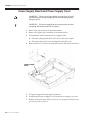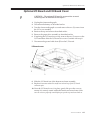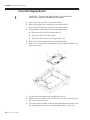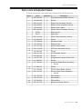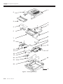
1
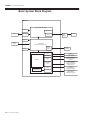
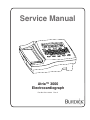
Service Manual
Atria™ 3000
Electrocardiograph
Part No. 070-1133-00
Rev. A
TO RESPONSIBLE SERVICE PERSONNEL:
The contents of this document are not binding. If any significant differences
between the product and this document are encountered regarding service
work, contact Quinton Cardiology, Inc. for further information.
Quinton Cardiology, Inc. recommends the use of authorized Quinton
Cardiology personnel for the maintenance and repair of all Burdick equipment.
Quinton Cardiology, Inc. cannot warrant the operation of the equipment if
other than Burdick genuine replacement or exchange parts are used in the
service or repair of this equipment, and if such service or repair is performed by
non-authorized personnel.
This product has been carefully designed to provide a high degree of safety and
dependability. However, we can not guarantee against the deterioration of components due to aging and normal wear.
CAUTION — The Atria 3000 ECG is a restricted device. Federal law restricts
the sale, distribution, or use of this device to, by, or on the lawful order of a
health professional.
DANGER — Explosion hazard. Do not use this device in the presence of flammable anesthetics.
Copyright © 2005 Quinton Cardiology, Inc.
All rights reserved.
Quinton Cardiology, Inc.
3303 Monte Villa Parkway
Bothell, Washington 98021-8969
(800) 426-0337
(425) 402-2000
Authorized Representative
per MDD 93/42/EEC
MDSS
Burckhardtstrasse 1
D-30163 Hannover, Germany
Table of Contents
Warnings & Cautions . . . . . . . . . . . . . . . . . . . . . . . . . . . . . . . . . . . . . . . . . . iii
Definitions of Symbols Used . . . . . . . . . . . . . . . . . . . . . . . . . . . . . . . . . . . . v
Chapter 1
General Information . . . . . . . . . . . . . . . . . . . . . . . . . . . . . . . . . . . . . . . 1-1
About the Atria Electrocardiographs . . . . . . . . . . . . . . . . . . . . . . . . . . . . 1-1
Basic System Description . . . . . . . . . . . . . . . . . . . . . . . . . . . . . . . . . . . . . . 1-1
Basic System Block Diagram . . . . . . . . . . . . . . . . . . . . . . . . . . . . . . . . . . . 1-2
Technical Specifications . . . . . . . . . . . . . . . . . . . . . . . . . . . . . . . . . . . . . . . 1-3
Chapter 2
Service & Maintenance . . . . . . . . . . . . . . . . . . . . . . . . . . . . . . . . . . . . 2-1
What You Will Need . . . . . . . . . . . . . . . . . . . . . . . . . . . . . . . . . . . . . . . . . . 2-1
Before You Begin . . . . . . . . . . . . . . . . . . . . . . . . . . . . . . . . . . . . . . . . . . . . . 2-1
Preventive Maintenance . . . . . . . . . . . . . . . . . . . . . . . . . . . . . . . . . . . . . . . 2-1
Visual Inspection . . . . . . . . . . . . . . . . . . . . . . . . . . . . . . . . . . . . . . . . . . .
Cleaning . . . . . . . . . . . . . . . . . . . . . . . . . . . . . . . . . . . . . . . . . . . . . . . . . .
Power Cable and Brick Cable . . . . . . . . . . . . . . . . . . . . . . . . . . . . . . . .
Patient Cable . . . . . . . . . . . . . . . . . . . . . . . . . . . . . . . . . . . . . . . . . . . . . .
Printhead . . . . . . . . . . . . . . . . . . . . . . . . . . . . . . . . . . . . . . . . . . . . . . . . .
Service Function Menus and Options . . . . . . . . . . . . . . . . . . . . . . . . . . . .
2-2
2-2
2-2
2-2
2-3
2-3
Setup Menu . . . . . . . . . . . . . . . . . . . . . . . . . . . . . . . . . . . . . . . . . . . . . . .
Hidden Menu . . . . . . . . . . . . . . . . . . . . . . . . . . . . . . . . . . . . . . . . . . . . . .
Special Functions Menu . . . . . . . . . . . . . . . . . . . . . . . . . . . . . . . . . . . . .
Measuring Chassis Leakage Current . . . . . . . . . . . . . . . . . . . . . . . . . . . .
2-3
2-4
2-5
2-7
Measuring Patient Leakage Current . . . . . . . . . . . . . . . . . . . . . . . . . . . . . 2-8
Chapter 3
Problem Solving . . . . . . . . . . . . . . . . . . . . . . . . . . . . . . . . . . . . . . . . . . . . 3-1
Troubleshooting . . . . . . . . . . . . . . . . . . . . . . . . . . . . . . . . . . . . . . . . . . . . . . 3-1
Connector Pinouts . . . . . . . . . . . . . . . . . . . . . . . . . . . . . . . . . . . . . . . . . . . . 3-4
Power In . . . . . . . . . . . . . . . . . . . . . . . . . . . . . . . . . . . . . . . . . . . . . . . . . . 3-4
Power Supply Board . . . . . . . . . . . . . . . . . . . . . . . . . . . . . . . . . . . . . . . . 3-4
Battery . . . . . . . . . . . . . . . . . . . . . . . . . . . . . . . . . . . . . . . . . . . . . . . . . . . . 3-5
Chapter 4
Component Replacement . . . . . . . . . . . . . . . . . . . . . . . . . . . . . . . . . . 4-1
Battery . . . . . . . . . . . . . . . . . . . . . . . . . . . . . . . . . . . . . . . . . . . . . . . . . . . . . . 4-2
Top Enclosure . . . . . . . . . . . . . . . . . . . . . . . . . . . . . . . . . . . . . . . . . . . . . . . . 4-3
Paper Drive Assembly . . . . . . . . . . . . . . . . . . . . . . . . . . . . . . . . . . . . . . . . 4-4
Queue Sensor . . . . . . . . . . . . . . . . . . . . . . . . . . . . . . . . . . . . . . . . . . . . . . . . 4-5
Atria Service Manual
i
Power Supply Board and Power Supply Cover . . . . . . . . . . . . . . . . . . . 4-6
Optional I/O Board and I/O Board Cover . . . . . . . . . . . . . . . . . . . . . . . 4-7
Front End Digital Board . . . . . . . . . . . . . . . . . . . . . . . . . . . . . . . . . . . . . . . 4-8
Parts Lists & Exploded Views . . . . . . . . . . . . . . . . . . . . . . . . . . . . . . . . . . 4-9
Index . . . . . . . . . . . . . . . . . . . . . . . . . . . . . . . . . . . . . . . . . . . . . . . . . . . . . . . In-1
ii
Atria Service Manual
Warnings & Cautions
Warnings
WARNING: There can be high voltage near the fuse, AC inlet and
transformer. Always unplug the electrocardiograph before taking it
apart.
Cautions
CAUTION: Always turn the electrocardiograph off and disconnect
the power cord before cleaning. Do not pour liquids (such as alcohol or
other cleaners) on the unit. This will cause severe electrical damage!
CAUTION: Setting the printhead resistance to any value other than
the value written on the printhead will shorten the life expectancy of
the printhead and may void your warranty.
CAUTION: Several of the electrocardiograph’s components are
extremely sensitive to static electricity. To minimize the risk of damage,
use a grounding strap and work on an antistatic surface.
CAUTION: The LCD is very sensitive to static electricity. Use an
antistatic work surface.
CAUTION: The queue sensor is very sensitive to static electricity. Use
an antistatic work surface.
CAUTION: The printhead is very sensitive to static electricity. Use an
antistatic work surface.
CAUTION: The optional I/O board is very sensitive to static
electricity. Use an antistatic work surface.
CAUTION: The front end digital board is very sensitive to static
electricity. Use an antistatic work surface.
CAUTION: The power supply board is very sensitive to static
electricity. Use an antistatic work surface.
Atria Service Manual
iii
iv
Atria Service Manual
Definitions of Symbols Used
Attention. Consult accompanying documents.
Danger! High voltage.
Hazardous voltage.
Defibrillation-Protected Type CF Equipment.
Equipotentiality (used to label the grounding lug).
Alternating Current (AC).
Direct Current (DC).
Automatic Operation.
Manual Operation.
On/Standby.
Stop Function.
Modem port.
Ethernet port.
USB port.
I0I0
Serial port.
Analog port.
Indoor, dry location use only.
No serviceable parts inside.
Meets or exceeds Council Directive 93/42/EEC, MDD, Class IIa.
Atria Service Manual
v
Certified for both the U.S. and Canadian markets, to the applicable U.S. and
Canadian safety standards.
Component is certified for both the U.S. and Canadian markets, to the
applicable U.S. and Canadian safety standards.
Device or component is certified for the Japanese and/or Asian markets.
vi
Atria Service Manual
Chapter
1
General Information
About the Atria Electrocardiographs
The Atria ECG is a multichannel non-interpretive/interpretive
electrocardiograph. You operate the electrocardiograph by pressing
various keys on the keypad. A thermal printer makes hard copy
printouts of text and waveforms for permanent records.
The servicing of the Atria electrocardiograph is similar regardless of
which model you have. Some of the information in this Service Manual
applies only to options which you may or may not have installed in
your electrocardiograph. Unless otherwise specified, the information in
this Service Manual applies to the Atria electrocardiographs.
Basic System Description
A simple diagram of the system is shown in Figure . When AC power
is not connected, an internal 14.4 V NiMH battery provides power for
all functions. This battery is recharged whenever the AC line is
connected.
The ECG data is acquired by hybrid circuits and sophisticated software
on the Logic board. Under microprocessor control, the
electrocardiograph samples, buffers and amplifies the analog ECG
signals before converting them to digital levels for further processing.
Input/output control circuitry handles communication with the front
end ECG signals, LCD (liquid crystal display), membrane switches,
thermal printer and external devices (if equipped).
Atria Service Manual
1-1
Chapter 1 General Information
Basic System Block Diagram
Atria 3000
Power Supply/Printer Board
Battery
Paper
Equipotential
Printer
Power In
Isolation
Supply
(Brick)
AC Power
KeyBoard
Patient
Cable
Atria Main Board
(Front end and Host processor)
Upgrade
Compact
Flash
LCD
Software
Upgrades
Optional I/O
IRDA
Printer
Analog Out
1mV =1V out/
Diagnostic equipment
RS232
External Modems
Database Management
Systems
Dual USB
Host
Software Upgrades
Printers / Database
Management Systems/
Wireless devices
I/O Board
RJ45
Optional Modem
Ethernet
Printers/Database
Management Systems
RJ11
Analog Phone Lines
Faxes /Database
Management Systems
1-2
Atria Service Manual
Technical Specifications
Technical Specifications
Dimensions:
15.0" x 13.125" x 5.5"
(381mm x 334mm x 140mm)
Weight (unit only):
11 lbs (5 kg) (including external power supply)
Display:
Backlit 2 X 40 character LCD
Keyboard:
Full alphanumeric keypad plus designated quick keys
Data Storage:
4 records standard, optional upgrade to 40 or 80
Power Requirements:
AC operation
115/230 V AC ±10%, 50/60 Hz at the external power
source
Battery operation
14.4 V NiMH rechargeable battery pack
Battery duration
30 minutes continuous printing or 30 ECGs
Printout:
Printout device
216 mm thermal dot array
Paper dimension
8.5" x 11" (US letter)
210mm x 300mm (A4)
Paper type
Thermal sensitive (Burdick Assurance® or
Heartline™ paper recommended)
Chart speeds
10, 25, 50 mm/sec
Gain
5, 10, 20 mm/mV Chest or Limb (may be split)
Printout formats
3, 4, 6 or 12 channels; additional rhythm formats
Acquisition:
Lead selection
I, II, III, aVR, aVL, aVF, V1, V2, V3, V4, V5, V6
Supports Frank X,Y, Z; Nehb D,A,J; and Alternate
Chest Lead (chest lead selection V2R through V9R,
V7, V8, and V9)
Modes
Automatic, automatic rhythm, or manual rhythm
Frequency response
Meets or exceeds ANSI/AAMI EC11-1991 standard
Input impedance
Meets or exceeds ANSI/AAMI EC11-1991 standard
Electrode offset tolerance
±300 mV
Effective A/D resolution
5µV LSB
Artifact filter response
40 Hz, -3db
Data resolution
500 samples/second, 5µV
Pacemaker display capability
Meets or exceeds ANSI/AAMI EC11-1991 standard
Interpretation (optional)
Diagnosis, measurements, reasons statements
based on five demographic criteria
Atria Service Manual
1-3
Chapter 1 General Information
Environmental:
Operating temperature
50°F to 104°F (10°C to 40°C)
Operating relative humidity
10% to 95% non-condensing
Operating atmospheric pressure
1060 hPa to 700 hPa (-500 ft to 10,000 ft reference to
sea level)
Storage temperature
-4°F to 131°F (-20°C to 55°C)
Storage relative humidity
25% to 95% non-condensing
Storage atmospheric pressure
1060 hPa to 190 hPa (-500 ft to 40,000 ft reference to
sea level)
Input/Output:
(units with communications)
telephone line interface (RJ11)
Ethernet (RJ45)
USB type A
standard RS-232 (9 pin “D”)
analog output (3.5mm phono plug))
IrDA
Conforms to Standards:
CAN/CSA-C22.2 No. 0-M91
CAN/CSA-C22.2 No. 601.1-M90
CAN/CSA-C22.2 No. 601.1S1
CSA C22.2 No. 601.2.25
UL 2601.1
EN 60601-1
EN 60601-2-25 & Amend. 1, excluding 36202.5
EN 60601-1-2, excluding 36.202.6
AZ/NZS 2064.1/2
ANSI/AAMI EC11 - 1991
Safety:
1-4
Atria Service Manual
Leakage current
patient <10 µA, chassis <100 µA
Defibrillation protection
to 5000V, 360J
Equipment Type:
Class IIa (Council Directive 93/42/EEC, MDD)
IEC 601-1 Class I, Type CF
Warranty:
3 years with return of warranty card
Chapter
2
Service & Maintenance
What You Will Need
You will need only standard electronics tools to perform any testing or repairs.
Test equipment must be in good condition and calibrated regularly. You will
need:
✔ Digital Multimeter
✔ Leakage Current Meter/Safety Analyzer
✔ Electronic Heart Simulator
Before You Begin
A few words of caution are in order. Before you perform any service on the
electrocardiograph, be aware of:
High voltage. There can be high voltage near the fuse, power inlet, and
transformer. Always unplug the electrocardiograph and remove the battery
pack before taking it apart.
Static electricity. The CMOS (complimentary metal-oxide semiconductor)
chips on the electrocardiograph’s circuit board are extremely sensitive to static
electricity. The printhead and display are also sensitive to static. To minimize
the risk of damage, use a grounding strap and work on an antistatic surface.
Recording paper. Do not use wax-coated or blush-coated paper in the
electrocardiograph. It will damage the printhead. Use only approved thermal
paper.
Preventive Maintenance
The purpose of preventive maintenance is to reduce or eliminate future
problems. Keeping the electrocardiograph in good operating condition ensures
that it will perform safely and provide accurate recordings.
At least once a year, you should:
✔ Visually inspect the electrocardiograph
✔ Clean the electrocardiograph
✔ Check the power cord
✔ Check the patient cable
✔ Check the leakage currents
If a repair is required, only qualified technicians should do the work.
Atria Service Manual
2-1
Chapter 2 Service & Maintenance
Visual Inspection
Check for anything out of the ordinary. Are there any cracks or missing parts?
Are the cords and connectors damaged or weak? Does the electrocardiograph
seem to operate properly? If everything looks fine, but you still suspect a
problem, check inside the electrocardiograph for loose connections, burn
damage or contamination from liquids.
Cleaning
CAUTION: Always turn the electrocardiograph off and
disconnect the power cord before cleaning. Do not pour liquids
(such as alcohol or other cleaners) on the unit. This will cause
severe electrical damage!
The need for cleaning depends on the environment and how often the
electrocardiograph is used. Use a damp cloth to clean the housing. Avoid
abrasive cleaners or polishes. Wipe dry with a soft, clean cloth. Don’t forget to
wipe the paper compartment.
Power Cable and Brick Cable
Check the power cord and AC inlet for any visible signs of deterioration, loose
connections or burn damage.
Brick cable
Brick
Power cable
Patient Cable
Check the patient cable and input connector for any visible signs of damage or
loose connections. Disconnect the patient cable from the unit and inspect it for
short circuits, broken wires or poor contacts by measuring the resistance (10k
± 10%) for individual electrode leads.
2-2
Atria Service Manual
Service Function Menus and Options
Printhead
Keep the thermal array printhead free of dirt and other foreign materials.
WARNING: The printhead is very sensitive to static
electricity. Use an antistatic work surface.
Light printing (particularly at the baseline) may be an indication that the
printhead is dirty. Use a small amount of ethanol or isopropyl alcohol and a
lint-free swab to remove residue. Avoid abrasives or cleaners which may
damage the printhead.
Service Function Menus and Options
Setup Menu
Use the Setup menu to print system statistics and change the battery saver
mode.
To print system statistics:
NOTE: This function will print a report of various system
information. This information is divided into the following
categories: Thermal Printer, Power, Front End, Installed
Options, Communications, General, Operating System and
Version Information.
1. Press
.
2. Press
.
3. Press
to scroll to Print System Statistics.
4. Press
.
To change the battery saver mode:
NOTE: Modify this option to temporarily disable the auto
power down feature. This will remain in effect until you enable
it again or until you press
1. Press
.
2. Press
.
.
Atria Service Manual
2-3
Chapter 2 Service & Maintenance
3. Press
.
4. Press
to scroll to Battery Saver Mode.
5. Press
.
6. Press
to select ON or OFF.
7. Press
.
Hidden Menu
The Atria electrocardiographs have a Hidden Menu which you access by
pressing a specific key combination. The service functions in this menu enable
you to perform various tests to verify proper operation. This is also the location
where you set the resistance of the printhead to the correct value.
To access the Hidden Menu:
1. Press
.
2. Press
.
3. Press and hold down
and
. Simultaneously press
.
NOTE: If the administrator password has been enabled, then
you must enter the password to continue.
Once you are in the Hidden Menu, scroll through the list of options by
pressing
. Press
to select a function.
The service functions in the Hidden Menu are listed below.
NOTE: The first three items in the menu are related to product
upgrades and are not part of regular maintenance. These items
are not included below.
Keyboard Test
This function allows you to test the keyboard for proper functioning. Press any
key on the keyboard and verify that the display shows the key selected. This
test is used by Burdick manufacturing.
2-4
Atria Service Manual
Service Function Menus and Options
Factory Defaults
This function allows you to set all of the user programmable defaults back to
their original factory settings. The Atria automatically copies all backup files to
the active directories and powers down and back up again to ensure that the
new defaults are effective.
NOTE: All configuration values are reset to the default
values. Additionally, all passwords are cleared and must be
reset.
Printhead Resistance
Because individual printheads vary in resistance, you must enter the printhead
resistance whenever the logic PCB or paper drive assembly has been replaced.
To enter the printhead resistance:
1. Compare the displayed value to the value written on the
printhead.
2. If the displayed value is incorrect, press backspace three times
to erase the current setting and type in the value printed on the
printhead.
CAUTION: Setting the printhead resistance to any value
other than the value written on the printhead will shorten the
life expectancy of the printhead and may void your warranty.
Printer Test Sequence
This function prints out three test pages which you can use to verify that the
printer is printing correctly across the full width of the printhead.
Printer Test Alternate Sequence
This function prints out a series of test pages which you can use to verify that
the printer is printing correctly across the full width of the printhead. Printer
Test Alternate prints continuously until you press
.
Special Functions
This option is used to access the Special Functions menu (see below).
Special Functions Menu
The last option in the Hidden Menu is Special Functions. Use the
Special Functions menu to view, enable or disable features.
NOTE: There may be other functions in addition to those
described below. They are included for Burdick Inc.
Engineering use only.
Atria Service Manual
2-5
Chapter 2 Service & Maintenance
From the Hidden Menu:
1. Press
to scroll to Special Functions.
2. Press
.
3. Type FET
Continue with step 4 below; or, to enable a feature, continue with step 4 on
page 2-7.
To view or disable features:
4. Enter the following and press
:
999999983
5. Press
to scroll through the list of features.
NOTE: Some of the features listed are not available currently.
6. Press
to select a feature.
NOTE: You may only select features that are currently
enabled.
7. Press
to scroll to the OFF option.
8. Press
to disable the feature.
NOTE: For storage features, select a different storage capacity,
either 4, 40, or 80 and press
2-6
Atria Service Manual
9. Press
.
10. Press
.
11. Press
.
.
Measuring Chassis Leakage Current
Or, to enable features:
4. Enter the password and press
.
NOTE: Contact Burdick Technical Support Department for
the password, once the feature has been ordered.
5. Press
to select the listed feature.
6. Press
to scroll to the ON option.
7. Press
to enable the feature.
8. Press
.
9. Press
.
10. Press
.
Measuring Chassis Leakage Current
Use a high quality meter or safety analyzer capable of testing to AAMI
specifications. An inappropriate meter can produce erroneous leakage
readings. Do the leakage tests at a nonconductive work station.
Be careful! The meter must be suitably insulated and capable of withstanding
the power line voltage.
To check the chassis leakage current:
1. Connect a leakage meter between the chassis ground jack (at
rear panel) and power line ground. Make sure the leakage
current is less than 300µA.
2. Open ground line and verify that leakage current is less than
300µA.
3. Reverse line polarity and verify that leakage current is less than
300µA with ground closed.
4. With reversed polarity, open ground line and ensure leakage is
less than 300µA.
Atria Service Manual
2-7
Chapter 2 Service & Maintenance
Measuring Patient Leakage Current
Use a high quality meter or safety analyzer capable of testing to AAMI
specifications. An inappropriate meter can produce erroneous leakage
readings. Do the tests at a nonconductive work station.
Be careful! The meter must be suitably insulated and capable of withstanding
the power line voltage.
To check the patient leakage current:
1. Connect the patient cable to the Atria.
2. Connect all patient cable leads together (it’s easiest to use a
safety analyzer).
3. Connect a leakage meter between patient cable leads and power
line ground. Make sure the leakage is less than 10µA.
4. Open ground line and verify that leakage current is less than
10µA.
5. Reverse line polarity and verify that leakage current is less than
10µA with ground closed.
6. With reversed polarity, open ground line and ensure leakage is
less than 10µA.
2-8
Atria Service Manual
Chapter
3
Problem Solving
Troubleshooting
Past experience shows that most service calls are due to poor ECG technique
or broken cables. Before you take apart the electrocardiograph, make sure that
these things are not causing the problem. Make use of the Operating
Instructions manual. It contains useful information!
The following table should help you trace problems to a particular assembly.
The possible causes are listed in order of probability.
Symptom:
Possible cause:
Procedure:
No power on indication
- no power
- ensure AC cord is plugged
into AC source
- defective or poorly seated
power supply cable
- reseat or replace cable
- No AC at outlet
- connect the Atria power brick
to working AC outlet
- defective power supply
board
- replace power supply board
- defective power brick
- replace power brick
(green light on back panel)
Print motor does not run - dirty queue sensor
- clean queue sensor
- defective or poorly seated
queue sensor
- reseat or replace queue sensor
- defective or poorly seated
print motor cable
- reseat cable or replace paper
drive assembly
- defective motor
- replace paper drive assembly
- defective or poorly seated
power supply cable
- reseat or replace cable
- defective power supply
board
- replace power supply board
- defective front end digital
board
- replace front end digital
board
Atria Service Manual
3-1
Chapter 3 Problem Solving
Symptom:
Possible cause:
Procedure:
Motor turns but paper
does not queue
- dirty queue sensor
- clean queue sensor
- defective queue sensor
- replace queue sensor
- defective or poorly seated
power supply cable
- reseat or replace cable
- defective or poorly seated
queue sensor cable
- reseat or replace cable
- defective power supply
board
- replace power supply board
- defective or broken bracket
- replace bracket
- defective or broken gear on
paper door assembly
- replace paper door assembly
- paper cover not properly
seated
- reseat paper cover
- paper installed incorrectly
- reinstall paper
- wrong Burdick paper
installed
- contact Customer Service for
assistance
- defective or poorly seated
print head cable
- reseat or replace cable
- defective printhead
- replace paper drive assembly
- defective or poorly seated
power supply cable
- reseat or replace cable
- defective power supply
board
- replace power supply board
- defective front end digital
board
- replace front end digital
board
- dirty queue sensor
- clean queue sensor
- defective or poorly seated
queue sensor
- reseat or replace queue sensor
Paper feeds but there is
no trace or printing
Printing is too light or too - use of non-approved paper - replace with Burdick paper
dark
- paper setting does not match - configure Paper Type (in
paper
3-2
Atria Service Manual
System Settings) to match
paper
- printhead resistance not
entered correctly
- enter correct printhead
resistance
- defective or poorly seated
power supply cable
- reseat or replace cable
- defective power supply
board
- replace power supply board
- defective front end digital
board
- replace front end digital
board
- defective or poorly seated
print head cable
- reseat or replace cable
Troubleshooting
Symptom:
Possible cause:
Procedure:
No keypad response
- defective or poorly seated
keypad cable
- reseat cable or replace keypad
- defective keypad
- replace keypad
- defective front end digital
board
- replace front end digital
board
- clean the underside of the
- oil from hand lotions has
keypad and the top side of
permeated the keypad and
the keyboard using isopropyl
has created a barrier between
the keypad and the keyboard alcohol
No LCD display
Dim LCD
- defective or poorly seated
LCD cable
- reseat or replace LCD cable
- no power
- ensure power brick is
plugged into AC source or
ensure battery is fully
charged
- keyboard connector not
properly seated
- ensure keyboard connector is
pushed all the way in
- defective keypad
- replace keypad
- defective LCD
- replace LCD
- defective or poorly seated
power supply cable
- reseat or replace cable
- defective power supply
board
- replace power supply board
- defective front end digital
board
- replace front end digital
board
- defective front end digital
board
- replace front end digital
board
- incorrect setting for
contrast/ brightness
- toggle contrast/ brightness
- defective LCD
- replace LCD
Will not store patient data - Directory is full
or ECG
Will not retain date and
time
- delete records from the
Directory
- defective front end digital
board
- replace front end digital
board
- defective or poorly seated
compact flash card
- replace or reseat compact
flash card
- low or dead lithium battery
- replace lithium battery
- bent battery holder
- replace front end digital
board
- defective front end digital
board
- replace front end digital
board
- poorly seated lithium battery - reseat or replace lithium
battery
Atria Service Manual
3-3
Chapter 3 Problem Solving
Connector Pinouts
You can use the following tables to help locate signals during troubleshooting.
Power In
The power connector uses a 6-pin 0.1” center MTA style header.
1
1
DC in + 24V
2
2
DC in - 0V
3
3
SAFETY GROUND
4
4
NC/POLARIZER
5
5
SAFETY GROUND
6
6
SAFETY GROUND
Power Supply Board
The printer/power supply connector is a 17 x 2, 0.1” center polarized header.
1
33
3-4
Atria Service Manual
2
34
1
GND
2
PRN CLK
3
GND
4
PRN DATA
5
GND
6
PRN LATCH
7
GND
8
PRN STROBE1
9
GND
10
PRN STROBE2
11
GND
12
GND
13
MOTOR 5
14
MOTOR 4
15
MOTOR 3
16
MOTOR 2
17
MOTOR 1
18
MOTOR 0
19
PREREGRWR
20
MT REF1
21
MT REF2
22
PREREGRWR
23
/ADC CS
24
ADC DIN
25
ADC DOUT
26
VCC5
27
ADC CLK
28
VCC5
29
AC DETECT
30
VPRINT ENABLE
31
VCC ENABLE
32
AC PWR UP
33
QUE
34
GND
Connector Pinouts
Battery
The battery uses a 4-conductor card edge connector.
4
3
2
1
1
BAT POSITIVE
2
BAT POSITIVE
3
BAT NEGATIVE
4
BAT NEGATIVE
Atria Service Manual
3-5
Chapter 3 Problem Solving
3-6
Atria Service Manual
Chapter
4
Component Replacement
This section contains instructions for removing and replacing the Atria
electrocardiograph’s major subassemblies. To find an assembly, refer to “Parts
Lists & Exploded Views” on pg. 4-9.
WARNING: There can be high voltage near the power brick
AC inlet. Always unplug the electrocardiograph before taking it
apart.
CAUTION: Several of the electrocardiograph’s components
are extremely sensitive to static electricity. To minimize the
risk of damage, use a grounding strap and work on an antistatic
surface.
NOTE: When you remove an assembly, pay close attention to
the wire and connector positions. This will make it easier to put
back together!
Atria Service Manual
4-1
Chapter 4 Component Replacement
Battery
WARNING: Never remove the battery pack and attempt to
recharge it using an external battery charger. Fire or explosion
may result.
WARNING: Verify that external power is disconnected before
removing or replacing battery. A blank display is not a reliable
indication of disconnected external power.
WARNING: Fire hazard. Use only an approved battery pack.
Replace battery pack with the battery specified on the label
inside the battery compartment.
NOTICE: Return used battery packs to an appropriate battery
recycler. Contact your local waste management officials for
more information.
1. Disconnect external power.
2. Remove the paper tray cover and paper.
3. Remove metal plate by pushing it toward the back of the unit, and then
lifting.
4. Disconnect battery by grasping the connector and sliding it straight
out. DO NOT PULL ON WIRES!
5. Remove battery by pulling it toward the back of the unit and then
lifting it out.
Metal Plate
Back
Front
Connector
Metal Plate
6. Replace in reverse order.
4-2
Atria Service Manual
Battery Pack
Top Enclosure
Top Enclosure
1. Unplug the electrocardiograph.
2. Disconnect the battery as described earlier.
3. Turn the electrocardiograph over and remove the two (2) screws from
the bottom of the electrocardiograph (screws are located on left side of
bottom enclosure).
4. Carefully turn electrocardiograph back over and remove the paper tray
cover and paper.
5. Remove the two (2) screws from the paper well (screws are located on
the left side of the electrocardiograph).
6. Lift up on top enclosure and disconnect the two connectors from the
top enclosure:
✔ Note the orientation of the connector, then disconnect the
LCD connector by sliding the cable out of the clip.
✔ disconnect the keyboard connector
7. Replace in reverse order. When you put the top enclosure back on, make sure
it does not pinch any internal wires.
CAUTION: When reconnecting the LCD to the top enclosure,
reconnect the cable with pin 1 closest to the keyboard.
Otherwise, the LCD display could be damaged.
Atria Service Manual
4-3
Chapter 4 Component Replacement
Paper Drive Assembly
NOTE: The paper drive assembly is replaced as a unit. Do not
disassemble.
CAUTION: The printhead is very sensitive to static
electricity. Use an antistatic work surface.
1. Unplug the electrocardiograph and disconnect the battery as
described earlier.
2. Remove top enclosure as described earlier.
3. Remove the two (2) screws from the right side of the assembly.
4. Carefully lift the paper drive assembly out of the bottom enclosure;
rotate the assembly 180° and set aside.
5. Disconnect the two (2) green and yellow ground cables from the paper
drive assembly.
6. Disconnect the connectors from the power supply board:
✔ Disconnect the 15-pin printhead cable
✔ Disconnect the 16-pin printhead cable
✔ Disconnect the queue sensor cable
✔ Disconnect the stepper motor cable
4-digit #
(printhead
resistance)
7. Replace in reverse order.
8. Locate the 4-digit number on the top metal printhead bracket and
record the printhead resistance (see “Printhead Resistance” on pg. 2-5).
4-4
Atria Service Manual
Queue Sensor
Queue Sensor
CAUTION: The queue sensor is very sensitive to static
electricity. Use an antistatic work surface.
1. Remove the top enclosure as described earlier.
2. Disconnect queue sensor from paper drive assembly.
3. Remove plastic screw and nut from paper drive assembly.
4. Replace in reverse order.
5. After installing the plastic nut, peen the threads on the plastic screw to
keep the nut from loosening.
Atria Service Manual
4-5
Chapter 4 Component Replacement
Power Supply Board and Power Supply Cover
WARNING: There can be high voltage near the fuse, AC inlet
and transformer. Always unplug the electrocardiograph before
taking it apart.
CAUTION: The power supply board is very sensitive to static
electricity. Use an antistatic work surface.
1. Remove the top enclosure as described earlier.
2. Remove the paper drive assembly as described earlier.
3. Disconnect the cables from the power supply board:
✔ Disconnect the ground cable at P1, next to the power input
✔ Disconnect the 34-pin front end digital board cable at J2
4. Remove the five (5) screws securing the board to the bottom enclosure.
power supply
cover
5. Lift power supply board straight up and out.
6. If replacing the power supply cover, lift the power supply cover out.
7. Replace in reverse order. Make sure all wires are properly routed before you
put the top enclosure back on.
4-6
Atria Service Manual
Optional I/O Board and I/O Board Cover
Optional I/O Board and I/O Board Cover
CAUTION: The optional I/O board is very sensitive to static
electricity. Use an antistatic work surface.
1. Unplug the electrocardiograph.
2. Disconnect the battery as described earlier.
3. Turn the electrocardiograph over and remove the two (2) screws from
the I/O cover assembly.
4. Remove the top enclosure as described earlier.
5. Remove the paper drive assembly as described earlier.
6. If replacing the I/O board cover only, remove the two (2) screws on the
I/O board then slide the I/O board cover out. Continue with step 9.
7. Disconnect the ground cable from JP9 on the I/O board.
I/O board cover
8. Slide the I/O board out of the bottom enclosure assembly.
9. Replace in reverse order. Be careful not to bend any of the I/O board
connector pins.
10. Once the I/O board cover is in place, gently lift up on the cover to
ensure it is securely seated within the bottom enclosure frame. Make
sure all wires are properly routed before you put the top enclosure back on.
Atria Service Manual
4-7
Chapter 4 Component Replacement
Front End Digital Board
CAUTION: The front end digital board is very sensitive to
static electricity. Use an antistatic work surface.
1. Remove the top enclosure as described earlier.
2. Remove the paper drive assembly as described earlier.
3. Remove the I/O board (if present) as described earlier.
4. Disconnect the cables from the front end digital board:
✔ Disconnect the 18-pin keyboard cable at J7
✔ Disconnect the LCD cable at JP23
✔ Disconnect the 34-pin power supply cable at J3
5. Remove the PC card from the front end digital board.
6. Remove the six (6) screws securing the front end digital board to the
bottom enclosure.
7. Lift the front end digital board straight up and out.
8. Replace in reverse order. Make sure all wires are properly routed before you
put the top enclosure back on.
9. Locate the 4-digit number on the metal printhead bracket and record
the printhead resistance (see “Printhead Resistance” on pg. 2-5).
4-8
Atria Service Manual
Parts Lists & Exploded Views
Parts Lists & Exploded Views
To locate components, refer to the figure on page 4-10 and this parts list:
Item #
Part #
Quantity
Description
1
650-1421-00
1
Top Enclosure Assembly, Service
2
215-0223-00
4
Screw
3
650-1414-00
1
Paper Door Assembly, Service
4
650-1464-00
1
Battery Cover Assembly, Service
5
146-0126-00
1
Battery Pack, NiMH
6
650-1420-00
1
Queue Sensor Assembly, Service
700257
1
Nylon Screw
703117
1
Nylon Nut
7
650-1416-00
1
Paper Drive Assembly, Service
8
215-0223-00
2
Screw
9
175-1566-00
1
Keyboard Cable
10
175-1570-00
1
Display Cable
11
175-1571-00
1
Power Supply Cable
12
650-1418-00
1
I/O Cover Assembly, Service
13
215-0223-00
2
Screw
14
650-1441-00
1
I/O Assembly, Service
215-0223-00
2
Screw
15
174-1677-00
1
Programmed Compact Flash Card
16
211-0466-00
6
Screw
17
671-1002-04
1
Front End Digital Board Assembly,
Service
18
211-0466-00
5
Screw
19
671-1268-00
1
Power Supply Board, Service
20
650-1419-00
1
Power Supply Cover Assembly,
Service
175-1572-00
1
Ground Wire
21
175-1573-00
2
Ground Wire
22
175-1603-00
1
Ground Wire
23
650-1417-00
1
Bottom Assembly, Service
Atria Service Manual
4-9
Chapter 4 Component Replacement
1
2
3
6
8
4
5
9
10
7
11
15
12
16
13
14
17
18
19
20
23
21
22
2
Figure 1 - Atria Exploded View
4-10
Atria Service Manual
Index
B
P
battery saver mode, 2-3
paper drive assembly, replacement, 4-4
battery, replacement, 4-2
parts list, 4-9
block diagram, 1-2
C
patient leakage current, 2-8
power down timer
See battery saver mode
power supply board, replacement, 4-6
cable maintenance, 2-2
preventive maintenance, 2-1
cautions, iii
printer test alternate sequence, 2-5
chassis leakage current, 2-7
printer test sequence, 2-5
cleaning, 2-2
printhead maintenance, 2-3
connector pinouts, 3-4
printhead resistance, 2-5
E
Q
environmental specifications, 1-4
queue sensor, replacement, 4-5
equipment type, 1-4
exploded view, 4-10
F
S
safety specifications, 1-4
service, 2-1
factory defaults, 2-5
service functions, 2-3
front end digital board, replacement,
4-8
special functions menu, 2-5
specifications, 1-3
symbols, v
H
hidden menu, 2-4
I
I/O board, replacement, 4-7
inspection, 2-2
K
keyboard test, 2-4
M
system description, 1-1
system statistics, 2-3
T
technical data, 1-3
tools, maintenance, 2-1
top enclosure, replacement, 4-3
troubleshooting, 3-1
W
warnings, iii
warranty, 1-4
maintenance, 2-1
Atria Service Manual
In-1
In-2 Atria Service Manual
Bothell, Washington 98021-8969
U.S.A. • (608) 764-1919