1
OWNER ’S GUIDE
INSTALLATION GUIDE
Video Multi-Control Unit
MODEL MCB1000
Table of Contents
Warranty . . . . . . . . . . . . . . . . . . . . . . . . .
Safety Instructions . . . . . . . . . . . . . . . . . .
Important Safeguards . . . . . . . . . . . . . . . .
Important Information . . . . . . . . . . . . . . .
FCC Notice . . . . . . . . . . . . . . . . . .
Your Warranty . . . . . . . . . . . . . . . .
Features . . . . . . . . . . . . . . . . . . . . . . . . .
Features . . . . . . . . . . . . . . . . . . . .
Accessories . . . . . . . . . . . . . . . . . .
Universal Remote Control . . . . . . . . . . . . .
Remote Control Operation . . . . . . . .
Remote Control Battery Install/Replace
Basic Operation . . . . . . . . . . . . . . . . . . . .
Turn the MCB 1000 On/Off . . . . . . . .
Turn Zone Monitors on/off . . . . . . . .
Selecting a Source . . . . . . . . . . . . .
Programming Menu . . . . . . . . . . . . .
Audio Through Vehicle Sound System .
Using the TV Tuner . . . . . . . . . . . . .
VCR Controls Buttons . . . . . . . . . . .
On-Screen Programming . . . . . . . . .
Hardware Options Menu . . . . . . . . . .
Installation . . . . . . . . . . . . . . . . . . . . . . .
Installation Precautions . . . . . . . . .
Installing the TVM 300 . . . . . . . . . .
TV Reception warning . . . . . . . . . . .
Wire and Cable Connections . . . . . . . . . . .
AV Source DIN to RCA . . . . . . . . . . .
System Capabilities Diagram . . . . . . . . . . .
Specifications . . . . . . . . . . . . . . . . . . . . .
2
.
.
.
.
.
.
.
.
.
.
.
.
.
.
.
.
.
.
.
.
.
.
.
.
.
.
.
.
.
.
.
.
.
.
.
.
.
.
.
.
.
.
.
.
.
.
.
.
.
.
.
.
.
.
.
.
.
.
.
.
.
.
.
.
.
.
.
.
.
.
.
.
.
.
.
.
.
.
.
.
.
.
.
.
.
.
.
.
.
.
.
.
.
.
.
.
.
.
.
.
.
.
.
.
.
.
.
.
.
.
.
.
.
.
.
.
.
.
.
.
.
.
.
.
.
.
.
.
.
.
.
.
.
.
.
.
.
.
.
.
.
.
.
.
.
.
.
.
.
.
.
.
.
.
.
.
.
.
.
.
.
.
.
.
.
.
.
.
.
.
.
.
.
.
.
.
.
.
.
.
.
.
.
.
.
.
.
.
.
.
.
.
.
.
.
.
.
.
.
.
.
.
.
.
.
.
.
.
.
.
.
.
.
.
.
.
.
.
.
.
.
.
.
.
.
.
.
.
.
.
.
.
.
.
.
.
.
.
.
.
.
.
.
.
.
.
.
.
.
.
.
.
.
.
.
.
.
.
.
.
.
.
.
.
.
.
.
.
.
.
.
.
.
.
.
.
.
.
.
.
.
.
.
.
.
.
.
.
.
.
.
.
.
.
.
.
.
.
.
.
.
.
.
.
.
.
.
.
.
.
.
.
.
.
.
.
.
.
.
.
.
.
.
.
.
.
.
.
.
.
.
.
.
.
.
.
.
.
.
.
.
.
.
.
.
.
.
.
.
.
.
.
.
.
.
.
.
.
.
.
.
.
.
.
.
.
.
.
.
.
.
.
.
.
.
.
.
.
.
.
.
.
.
.
.
.
.
.
.
.
.
.
.
.
.
.
.
.
.
.
.
.
.
.
.
.
.
.
.
.
.
.
.
.
.
.
.
.
.
.
.
.
.
.
.
.
.
.
.
.
.
.
.
.
.
.
.
.
.
.
.
.
.
.
.
.
.
.
.
.
.
.
.
.
.
.
.
.
.
.
.
.
.
.
.
.
.
.
.
.
.
.
.
.
.
.
.
.
.
.
.
.
.
.
.
.
.
.
.
.
.
.
.
.
.
.
.
.
.
.
.
.
.
.
.
.
.
.
.
.
.
.
.
.
.
.
.
.
.
.
.
.
.
.
.
.
.
.
.
.
.
.
.
.
.
.
.
.
.
.
.
.
.
.
.
.
.
.
.
.
.
.
.
.
.
.
.
.
.
.
.
.
.
.
.
.
.
.
.
.
.
.
.
.
.
.
.
.
.
.
.
.
.
.
.
.
.
.
.
.
.
.
.
.
.
.
.
.
.
.
.
.
.
.
.
.
.
.
.
.
.
.
.
.
.
.
.
.
.
.
.
.
.
.
.
.
.
.
.
.
.
.
.
.
.
.
.
.
.
.
.
.
.
.
.
.
.
.
.
.
.
.
.
.
.
.
.
.
.
.
.
.
.
.
.
.
.
.
.
.
.
.
.
.
.
.
.
.
.
.
.
.
.
.
.
.
.
.
.
.
.
.
.
.
.
.
.
.
.
.
.
.
.
.
.
.
.
.
.
.
.
.
.
.
.
.
.
.
.
.
.
.
.
.
.
.
.
.
.
.
.
.
.
.
.
.
.
.
.
.
.
.
.
.
.
.
.
.
.
.
.
.
.
.
.
.
.
.
.
.
.
.
.
.
.
.
.
.
.
.
.
.
.
.
.
.
.
.
.
.
.
.
.
.
.
.
.
.
.
.
.
.
.
.
.
.
.
.
.
.
.
.
.
.
.
.
.
.
.
.
.
.
.
.
.
.
.
.
.
.
.
.
.
.
.
.
.
.
.
.
.
.
.
.
.
.
.
.
.
.
.
.
.
.
.
.
.
.
.
.
.
.
.
.
.
.
.
.
.
.
.
.
.
.
.
.
.
.
.
.
.
.
.
.
.
.
.
.
.
.
.
.
.
.
.
.
.
.
.
.
.
.
.
.
.
.
.
.
.
.3
.4
.5
.5
.5
.5
.6
.6
.6
.7
.7
.7
.8
.8
.8
.8
.8
.8
.8
.9
.9
.9
.10
.10
.10
.11
.12
.13
.14
.15
© 2001 Directed Electronics, Inc.
Limited One-Year Warranty
For a period of ONE YEAR from the date of purchase,
Directed Electronics, Inc. ("DIRECTED") promises to the
original purchaser to repair or replace, free of cost,
with a comparable reconditioned model any VIDEO
MULTI-CONTROL UNIT (hereafter the "UNIT”), which
proves to be defective in workmanship or material
defect under normal use, provided the following conditions are met: the unit was purchased and installed by
an authorized DIRECTED dealer; the unit remains in the
vehicle in which the unit was originally installed; and
the unit is returned to DIRECTED. The unit in question
must be returned to DIRECTED postage paid and must
be accompanied by a clear, legible copy of the bill of
sale bearing the following information:
your authorized dealer to obtain the service charge for
your unit.
TO THE MAXIMUM EXTENT ALLOWED BY LAW, ALL
WARRANTIES, INCLUDING BUT NOT LIMITED TO
EXPRESS WARRANTY, IMPLIED WARRANTY, WARRANTY OF MERCHANTABILITY, FITNESS FOR PARTICULAR
PURPOSE AND WARRANTY OF NON-INFRINGEMENT OF
INTELLECTUAL PROPERTY, ARE EXPRESSLY EXCLUDED;
AND DIRECTED NEITHER ASSUMES NOR AUTHORIZES
ANY PERSON OR ENTITY TO ASSUME FOR IT ANY DUTY,
OBLIGATION OR LIABILITY IN CONNECTION WITH ITS
PRODUCTS.
DIRECTED DISCLAIMS AND HAS
ABSOLUTELY NO LIABILITY FOR ANY AND ALL ACTS
■
Date of Purchase
■
Your Full name and address
INSTALLERS. IN THE EVENT OF A CLAIM OR A DIS-
■
Authorized dealer's company name and address
PUTE INVOLVING DIRECTED OR ITS SUBSIDIARY, THE
■
Type of unit installed
PROPER VENUE SHALL BE SAN DIEGO COUNTY IN THE
■
Year, make, model, and color of the automobile
STATE OF CALIFORNIA. CALIFORNIA STATE LAWS AND
■
Automobile license number
APPLICABLE FEDERAL LAWS SHALL APPLY AND GOV-
■
Vehicle Identification number
ERN THE DISPUTE. THE MAXIMUM RECOVERY UNDER
■
Installation receipts
ANY CLAIM AGAINST DIRECTED SHALL BE STRICTLY
All components other than the unit, including and
without limitation the remote control, cables and
installation accessories, carry a 60-day warranty from
the date of purchase of the same.
OF
THIRD
PARTIES
INCLUDING
DEALERS
OR
LIMITED TO THE AUTHORIZED DIRECTED DEALER'S
PURCHASE PRICE OF THE UNIT. DIRECTED SHALL NOT
BE RESPONSIBLE FOR ANY DAMAGES WHATSOEVER,
INCLUDING BUT NOT LIMITED TO, ANY CONSEQUENTIAL DAMAGES, INCIDENTAL DAMAGES, DAMAGES
This warranty is automatically void if the unit's date
FOR THE LOSS OF TIME, LOSS OF EARNINGS, COM-
code or serial number is defaced, missing or altered;
MERCIAL LOSS, LOSS OF ECONOMIC OPPORTUNITY
the unit has been modified or used in a manner con-
AND THE LIKE. NOTWITHSTANDING THE ABOVE, THE
trary to its intended purpose; or the unit has been
MANUFACTURER DOES OFFER A LIMITED WARRANTY
damaged by accident, unreasonable use, neglect,
TO REPLACE OR REPAIR THE CONTROL MODULE AS
improper service, installation or other causes not aris-
DESCRIBED ABOVE. Some states do not allow limita-
ing out of defects in materials or construction. This
tions on how long an implied warranty will last or the
warranty is nontransferable and does not apply to any
exclusion or limitation of incidental or consequential
until that has been modified or used in a manner con-
damages. This warranty gives you specific legal rights
trary to its intended purpose and does not cover bat-
and you may also have other rights that vary from State
teries. This warranty does not cover labor costs for
to State. DIRECTED does not and has not authorized
the removal, diagnosis, troubleshooting or reinstalla-
any person or entity to create for it any other obliga-
tion of the unit. For service on an out-of-warranty
tion, promise, duty or obligation in connection with
product a flat fate fee by model is charged. Contact
these UNITS.
© 2001 Directed Electronics, Inc.
3
Safety Instructions
WARNING:
TO REDUCE THE RISK OF FIRE OR ELECTRIC SHOCK, DO NOT EXPOSE THIS EQUIPMENT TO
RAIN OR MOISTURE. TO REDUCE THE RISK OF FIRE OR ELECTRIC SHOCK AND ANNOYING
INTERFERENCE, USE ONLY THE INCLUDED HARDWARE.
DIRECTED ELECTRONICS, INC. DISCLAIMS ANY LIABILITY FOR ANY BODILY INJURY,
INCLUDING FATALITIES, OR PROPERTY DAMAGE THAT MAY RESULT FROM ANY IMPROPER OR
UNINTENDED USES OF THIS PRODUCT.
DO NOT MAKE MODIFICATIONS THAT WILL COMPROMISE ANY OF THE VEHICLES SAFETY
EQUIPMENT. MODIFYING OR CONNECTING TO WIRES FOR THE BRAKE OR LIGHTING SYSTEM
COULD CAUSE POTENTIALLY HAZARDOUS DRIVING SITUATIONS.
DO NOT MOUNT THIS OR ANY OTHER COMPONENT IN FRONT OF OR NEAR THE PASSENGER
AIR BAG. EXPLOSIVE AIR BAG DEPLOYMENT COULD THROW A COMPONENT TOWARD THE
PASSENGER CAUSING INJURY.
Read this manual in its entirety before beginning
try; therefore it is not recommended that the
the installation. It has important information
consumer try to install this system. Installations
about safety hazards during vehicle operation.
performed by unqualified persons could result in
This system is designed and intended for installation by MECP certified installers. It requires
tools, equipment and product installation tech-
damage to the vehicles electrical system. Please
consult with your authorized retailer to have
this system installed.
niques common to the Mobile Electronics indus-
4
© 2001 Directed Electronics, Inc.
Important Safeguards
1.
It is dangerous for the vehicle operator to
watch the video while driving and, in most
cases, it is illegal for the vehicle operator
to use a Mobile Video system while driving. Please be a safe driver. Any viewing by
the driver during vehicle operation could
cause a collision or injury.
2.
This unit does not have any consumerrepairable components. Any attempts to
alter this product could result in fire or
electric shock. Repairs performed by anyone other than an authorized repair facility will void the warranty.
3.
The only replaceable component to this
system is the optional TV tuner (TVM300),
and should only be installed by an authorized retailer.
4.
If the system stops working normally,
discontinue operation immediately and
consult your authorized retailer for service.
5.
Operate the system in a safe manner.
Excessively high volume levels that impair
your ability to hear noises from outside
the vehicle can be a hazard to yourself and
other motorists.
6.
Before attempting to make adjustments to
the system, move the vehicle to a safe
place away from traffic and stop. Driving
while distracted can cause accidents and
injuries.
Important Information
FCC NOTICE
YOUR WARRANTY
This device complies with Part 15 of FCC rules.
Your warranty registration must be completely
Operation is subject to the following two condi-
filled out and returned within 10 days of pur-
tions: (1) This device may not cause harmful
chase. Your product warranty will not be vali-
interference, and (2) this device must accept
dated if your warranty registration is not
any interference received, including interfer-
returned. Make sure you receive the warranty
ence that may cause undesired operation.
registration from your dealer. It is also neces-
Changes
or
modifications
not
expressly
approved by the party responsible for compliance could void the user's authority to operate
sary to keep your proof of purchase, which
reflects that the product was installed by an authorized dealer.
this device.
© 2001 Directed Electronics, Inc.
5
Features
The
MCB1000
Multi-Controller
Module
is
designed to be the centerpiece of a Mobile
Multi-Media System.
The universal IR remote can command any or all
sources from each of the systems monitors.
The Directed ESP/ESP2 security systems can be
With AV inputs for up to four sources (with
integrated with on-screen programming and
TVM300 TV tuner) and three AV outputs it can
trigger information
operate as three separate video systems at the
same time.
FEATURES
ACCESSORIES
■
Infrared remote control.
■
Multi-Control Unit.
■
Remote IR input from hidden source unit.
■
Universal Remote Control x 1.
■
Source on-screen display for all zones.
■
Batteries for Remote Control x 2.
3 external AV inputs for VCR, DVD, or Video
gaming.
■
5M Din-Din Cables x 3.
■
5M Din-RCA Input Cables x 2.
3 independently controlled AV output
zones.
■
5M ESP/ESP2 Cable x 1.
■
5M FM Modulator Control Cable x 1.
■
IR Eye with cap Cable x 1.
■
Power Cable x 1.
■
Mounting Screws x 4.
■
■
6
■
1 internal AV input for optional TV tuner.
■
Antenna or cable-ready TV tuner.
■
FM modulator control.
■
Audio input gain controls.
■
ESP/ESP2 Security System port for OSD of
programming and trigger reporting.
Note: This manual makes reference to optional Directed
Video parts not included with this product.
© 2001 Directed Electronics, Inc.
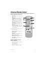
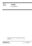
Universal Remote Control
REMOTE CONTROL OPERATION
1.
MAIN POWER - Turns power to the
MCB1000 on/off.
2.
PWR/SOURCE - Turns monitor power
on/off and changes the video source.
3.
FM MOD - Turns the power to the RFM100
FM modulator on/off if connected to the
MCB1000 FM modulator control output.
4.
ZONE BUTTONS - Selects which monitor
zone of the MCB1000 the remote control
will operate.
5.
MENU/ADJUST BUTTONS - Accesses the
setup menu and hardware programming
menus for the MCB1000.
NOTE: Refer to the On-screen Programming section for
programming information.
6.
NUMERIC BUTTONS - Use to choose specific TV channels.
7.
CHDN/CHUP - Changes channels if the
TVM300 TV tuner is connected.
8.
AUTO MEM - Activates the auto channel
learn of the TVM300 TV tuner.
9.
VCR CONTROL - Controls the basic
functions of the VCR.
REMOTE CONTROL BATTERY
INSTALL/REPLACE
1.
Slide battery compartment cover out from
back of remote control.
2
Insert two AAA batteries.
3.
Slide battery compartment cover back in.
© 2001 Directed Electronics, Inc.
7
Basic Operation
The RC100 can control the functions of the MCB
1000 zone monitors, the TVM300 TV tuner, the
VC2010 VCR, and the VC2050 VCR.
To operate a specific monitor, the remote con-
AUDIO THROUGH VEHICLE
SOUND SYSTEM
■
Only available with the RFM100 connected.
■
Select the zone that the RFM100 is
connected to. Press the FM MOD (3)
button. Set the vehicles radio to the
correct frequency and the audio from that
source will be heard through the vehicles
sound system.
trols zone button (4) for that monitor must first
be selected.
TURN THE MCB1000 ON/OFF
■
Press the MAIN POWER (1) button to turn
the MCB1000 on/off.
USING THE TV TUNER
TURN ZONE MONITORS ON/OFF
MEMORIZING CHANNELS
■
Press the ZONE (4) button for the monitor
you want to turn on.
■
■
Press the PWR/SOURCE (2) button to turn
the monitor on. Press the PWR/SOURCE
(2) button for more than three seconds to
turn the monitor off.
With the TV tuner as the source, press the
CHDN/CHUP (7) buttons. The channel will
move up or down one channel at a time.
Press and hold to tune through channels at
a rapid rate.
CHANGING CHANNELS
SELECTING A SOURCE
■
■
With the zone monitor on, press the
PWR/SOURCE (2) button for less than
three seconds to toggle through all
connected video sources.
With the TV tuner as the source, press the
AUTO MEM (8) button. The TV tuner will
start searching for stations, adding to
memory any channels within reception
range.
NUMERIC BUTTONS
■
PROGRAMMING MENU
■
8
All on-screen programming can be
performed using the MENU/ADJUST (5)
buttons. Refer to the On-screen
Programming section for programming
information.
Channels can be directly selected by using
the Numeric (6) buttons. When the channel
number is selected, it will appear on the
screen for a few seconds then the TV tuner
will change to the selected channel.
ANTENNA/CATV
■
When in an area where cable is available
the TVM300 can accept up to 125 channels
of CATV input. Refer to the programming
menu to change from Antenna to CATV.
© 2001 Directed Electronics, Inc.
VCR CONTROLS BUTTONS
■
The VCR control buttons (9) will operate
■
Directed video's VC2010 and VC2050 Video
■
Cassette Recorders
■
PWR button - Turns the VCR power on/off
■
RR button
■
Press in stop mode to fast rewind the
tape.
■
Press in play mode to rewind search.
Play button - Press to begin tape playback
■
FF button
■
Press again to resume normal tape
playback
Press repeatedly when tape is paused
to advance one frame at a time.
Press and hold when tape is paused
for three seconds to activate slow
motion playback
ON-SCREEN PROGRAMMING
The MCB1000 hardware functions and on-screen
display can be customized at the time of installation.
Press to fast-forward the tape when
in stop mode.
■
Press to forward search the tape in
play mode.
CN/TRK buttons
On-screen programming is only available when
Monitor.
■
Press to manually adjusts tape
tracking when in play mode.
■
Press to change the TV channels.
Only available of the VCR has a built
in TV tuner.
Stop button - Press to stop tape playback.
■
Pause button
Please use the Hardware Options Menu below for
■
■
■
■
Press to pause tape playback.
integrating with Directeds HVM500, RVM560,
RVM680 and RVM700 video monitors. For a complete guide to On-screen Programming see the
Owner/Installation guide for your Directed Video
The Expanded Menu switch on the MCB1000
module must be on for the Setup Menu to appear
on screen.
more information.
HARDWARE OPTIONS MENU
SELECTION
DESCRIPTION AND OPERATION
POWER AUTO OFF
■
■
■
FM MODULATOR
■
■
© 2001 Directed Electronics, Inc.
Select to choose POWER AUTO OFF or POWER LAST STATE.
POWER AUTO OFF - When the key is turned on the
system power will remain off, regardless of the system on/off state when the key was turned off.
POWER LAST STATE - When the key is turned on the
system will automatically return to the power
on/off state it was in when the key was turned off.
Select to let the MCB1000 know an FM modulator is
connected.
FM MODULATOR - allows the universal remote to turn
9
■
■
ANTENNA TV
■
■
■
CATV STD
■
■
■
■
the FM modulator on/off.
NO FM MODULATOR - FM modulator control is defeated.
This FM Modulator function only applies when the
RFM100 is connected.
Select to choose Antenna or Cable input to TVM300.
Select ANTENNA TV when the TVA10 antenna is connected to the TVM300.
Select CATV when using a cable TV connection to
the TVM300.
Choose between three types of cable TV setups.
CATV STD - standard cable system for cable-ready TV's.
CATV HRC - for non-cable ready TV's.
CATV IRC - for non-cable ready TV's.
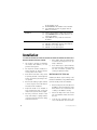
Installation
INSTALLATION PRECAUTIONS
1.
Before drilling, always check behind panels
for clearance to factory wires, hoses, gas
tanks, or brake lines.
8.
Fuses should only be replaced with like
fuses of the same value. If the replacement
fuse fails, discontinue operation and
contact your authorized retailer.
2.
All components should be installed in a
manner that will not interfere with the
normal operation of the vehicle.
3.
Route all wires and cables so they cannot
be pinched, punctured, or chaffed by sharp
metal or screws during reassembly or vehicle operation.
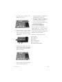
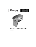
INSTALLING THE TVM 300
Disconnect the battery’s negative terminal
or remove any fuses from circuits that are
affected before the installation.
technician should perform this installation.
4.
10
This product is designed for installation
into vehicles with standard (-) 12 volt
ground electrical systems.
7.
5.
Components should not be installed on
areas of high moisture, dust, or heat, and
should not be exposed to direct sunlight.
6.
All wiring connections should be made
using solder and tape or quality solderless
connectors. Never leave bare wires. Always
terminate unused wires.
Installing the TVM300 requires working on the
PC board of the MCB1000. Only a MECP Certified
1.
Disconnect all power wires and cables from
the MCB1000 before beginning this installation. Failure to do so could result in fire
or damage to the MCB1000 circuitry.
2.
Remove the Philips head screws at both
ends of the MCB1000 module and remove
the cover.
3.
Locate the open rectangular area in the
corner of the PC board. This is the mount-
© 2001 Directed Electronics, Inc.
ing location. Note the location of the
female 20-pin connector.
7.
Verify that the TVM300 is secured and reinstall the MCB1000 module cover.
8.
Complete the installation/reinstallation of
the MCB1000. Verify all connections are
correct according to the instructions
9.
Be sure to attach the TV antenna, then
test the system operation.
TV RECEPTION WARNING
Television reception in an automobile is constantly affected due to vehicle movement
4.
Position the TVM300 over the mounting
location and check alignment of the
antenna connector slot in the case, the
20-pin connector, and the two machine
screw mounts.
5.
Carefully align the TVM300 to the 20-pin
connector and press down firmly until the
TVM300 mounting brackets align with the
machine screw mounts.
6.
Secure the TVM300 to the circuit board
with the supplied machine screws.
© 2001 Directed Electronics, Inc.
around obstructions and high-energy sources.
Location, weather, automobile construction, and
installation can all affect reception.
Possible areas of poor reception include:
■
Hospitals
■
Military bases
■
Airports
■
High power wires
■
Large buildings
■
Distance from transmitter
11
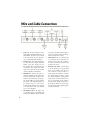
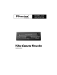
Wire and Cable Connections
1.
2.
12
Audio out - Use these outputs for stereo
audio signal to IR wireless headphones or an
FM modulator. The audio zones correspond
to the same monitor zones so any time a
source is changed the audio will follow.
Monitor zones - These eight-pin DIN plugs
are audio and video outputs. Using the
VDC100, they plug directly into the
Directed Video line of overhead and headrest monitors. They include stereo audio
signal, video signal, IR signal, and data
signal for ESP/ESP2 communication.
3.
ESP/ESP2 Port - This three-pin port is for
adding the ESP/ESP2 security system with
two-way communication. It allows information to flow between the security system and the MCB 1000. User-programmable features of the ESP/ESP2 systems can
be changed using on screen menus.
Security system violations can be reported
on screen with the name of the violated
zone or sensor displayed.
4.
FM Modulator control - This plug is used
for controlling power to the RFM100 FM
modulator. The MCB1000 will turn the RFM
100 power on/off by the ignition switch or
the system operator can turn the FM modulator on/off by remote control.
5.
Infrared input - This is a 3.5mm pin plug
for a remote IR eye. The optional IR 100
Infrared remote receiver can be added to
the system to allow full control from any
location in the vehicle.
6.
Extended menu switch - Set this switch
to the ON position and a special Setup
Menu for the installer will appear on
screen with the rest of the menus. It is
designed allow the installer to customize
the system hardware operation, program
the Directed ESP/ESP2 security system
trigger names, and name the AV zones for
the on-screen display. Set the switch to
the OFF position and the Setup Menu no
longer appears with the on-screen menus.
Refer to the On-screen Programming guide
for further information.
© 2001 Directed Electronics, Inc.
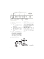
Capabilities Diagram.
1.
Indicator Led - Indicates power on/off
2.
Power connector:
4.
TV antenna connector - This is a standard
F-type TV antenna connector. It can be
connected to with Directed Video's TVA 10
telescoping antenna for broadcast TV or a
standard cable TV connection.
5.
Audio level controls - These are
adjustable source audio input level controls. When adjusting the system, all
source inputs should be matched for consistent volume level when changing
sources.
■
3.
RED - Accessory power. Connect to
(+) 12 volt wire that turns on/off
with the ignition.
■
YELLOW - Constant power. Connect to
(+) 12 volt wire that has constant
power.
■
BLACK - Connect to (-) chassis
ground.
AV source - These are eight-pin DIN connectors for three of the AV input zones.
Each connector provides input/outputs for
video, stereo audio, and Infrared remote
operation. For a guide to the capabilities
of the MCB 1000 refer to the System
AV SOURCE DIN TO RCA
IR EYE LINK
Low current only, or
else DO NOT connect
to source main power.
© 2001 Directed Electronics, Inc.
13
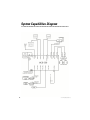
System Capabilities Diagram
14
© 2001 Directed Electronics, Inc.
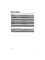
Specifications
MAIN UNIT
Product
Multi-Zone Audio/Video/TV system
Power requirement
12.5 Vdc (11-15Vdc)
Power consumption
700 mA in operation/60 mA standby
Audio input
1 volt rms max
Audio output
1.0 volt rms DIN/RCA
Video input
1 volt p-p 75 ohms
Video output
1 volt p-p 75 ohms
Dimensions
19.7cm x 13cm (7.75” x 5.125”)
Temp range
35-115 degrees farhenhiet
UNIVERSAL REMOTE CONTROL
Power source
3 volts DC 2x AAA Batteries
Infrared range
App. 2M (6.5 ft)
© 2001 Directed Electronics, Inc.
15
The company behind this system is Directed Electronics, Inc.
Since its inception, Directed has had one purpose, to provide consumers with the finest vehicle security, car stereo
products, rear seat entertainment, and accessories available. The recipient of more than 20 patents in the field of
advanced electronic technology, Directed is ISO 9001 registered.
Quality Directed Electronics products are sold and serviced throughout North America and around the world.
Call (800) 274-0200 for more information about our products and services.
Directed® is committed to delivering world-class quality products
and services that excite and delight our customers.
Directed Electronics, Inc.
Vista, CA 92083
www.directed.com
© 2001 Directed Electronics, Inc. - All rights reserved
N85201 Rev. 1.0 12-01