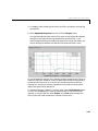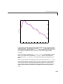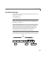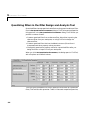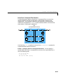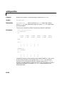
1
Filter Design Toolbox For Use with MATLAB ® Computation Visualization Programming User’s Guide Version 2 How to Contact The MathWorks: ☎ 508-647-7000 Phone 508-647-7001 Fax The MathWorks, Inc. 3 Apple Hill Drive Natick, MA 01760-2098 Mail http://www.mathworks.com Web Anonymous FTP server Newsgroup PHONE FAX ✉ MAIL INTERNET ftp.mathworks.com comp.soft-sys.matlab @ E-MAIL [email protected] [email protected] [email protected] [email protected] [email protected] [email protected] [email protected] Technical support Product enhancement suggestions Bug reports Documentation error reports Subscribing user registration Order status, license renewals, passcodes Sales, pricing, and general information Filter Design Toolbox User’s Guide COPYRIGHT 2000 by The MathWorks, Inc. The software described in this document is furnished under a license agreement. The software may be used or copied only under the terms of the license agreement. No part of this manual may be photocopied or reproduced in any form without prior written consent from The MathWorks, Inc. FEDERAL ACQUISITION: This provision applies to all acquisitions of the Program and Documentation by or for the federal government of the United States. By accepting delivery of the Program, the government hereby agrees that this software qualifies as "commercial" computer software within the meaning of FAR Part 12.212, DFARS Part 227.7202-1, DFARS Part 227.7202-3, DFARS Part 252.227-7013, and DFARS Part 252.227-7014. The terms and conditions of The MathWorks, Inc. Software License Agreement shall pertain to the government’s use and disclosure of the Program and Documentation, and shall supersede any conflicting contractual terms or conditions. If this license fails to meet the government’s minimum needs or is inconsistent in any respect with federal procurement law, the government agrees to return the Program and Documentation, unused, to MathWorks. MATLAB, Simulink, Stateflow, Handle Graphics, and Real-Time Workshop are registered trademarks, and Target Language Compiler is a trademark of The MathWorks, Inc. Other product or brand names are trademarks or registered trademarks of their respective holders. Printing History: March 2000 September 2000 New for Version 1.0 (online only) First Printing Revised for Version 2 (Release 12) Contents Preface What Is Filter Design Toolbox? . . . . . . . . . . . . . . . . . . . . . . . . . . xi Related Products List . . . . . . . . . . . . . . . . . . . . . . . . . . . . . . . . . . xii Using This Guide . . . . . . . . . . . . . . . . . . . . . . . . . . . . . . . . . . . . . xiii New Users of This Toolbox . . . . . . . . . . . . . . . . . . . . . . . . . . . . . xiii Experienced Users of This Toolbox . . . . . . . . . . . . . . . . . . . . . . . xiv Organization of This Guide . . . . . . . . . . . . . . . . . . . . . . . . . . . . . . xv Configuration Information . . . . . . . . . . . . . . . . . . . . . . . . . . . xvii Technical Conventions . . . . . . . . . . . . . . . . . . . . . . . . . . . . . . . xviii Typographical Conventions . . . . . . . . . . . . . . . . . . . . . . . . . . . xix Filter Design Toolbox Overview 1 Filter Design Functions in the Toolbox . . . . . . . . . . . . . . . . . 1-4 Quantization Functions in the Toolbox . . . . . . . . . . . . . . . . . Data Quantizers . . . . . . . . . . . . . . . . . . . . . . . . . . . . . . . . . . . . . Quantized Filters . . . . . . . . . . . . . . . . . . . . . . . . . . . . . . . . . . . . . Quantized Fast Fourier Transforms . . . . . . . . . . . . . . . . . . . . . 1-7 1-8 1-9 1-9 Comparison to the Signal Processing Toolbox . . . . . . . . . . 1-11 Filters in Signal Processing Toolbox . . . . . . . . . . . . . . . . . . . . 1-11 Filters in Filter Design Toolbox . . . . . . . . . . . . . . . . . . . . . . . . 1-13 i Getting Started with the Toolbox . . . . . . . . . . . . . . . . . . . . . . Example - Creating a Quantized IIR Filter . . . . . . . . . . . . . . . Designing the IIR Filter . . . . . . . . . . . . . . . . . . . . . . . . . . . . . . Quantizing the IIR Filter . . . . . . . . . . . . . . . . . . . . . . . . . . . . . . 1-15 1-15 1-17 1-20 Selected Bibliography . . . . . . . . . . . . . . . . . . . . . . . . . . . . . . . . 1-28 Designing Advanced Filters 2 The Optimal Filter Design Problem . . . . . . . . . . . . . . . . . . . . . 2-2 Optimal Filter Design Theory . . . . . . . . . . . . . . . . . . . . . . . . . . . 2-2 Optimal Filter Design Solutions . . . . . . . . . . . . . . . . . . . . . . . . . 2-5 Advanced FIR Filter Designs . . . . . . . . . . . . . . . . . . . . . . . . . . . 2-7 gremez Examples . . . . . . . . . . . . . . . . . . . . . . . . . . . . . . . . . . . . . 2-8 Advanced IIR Filter Designs . . . . . . . . . . . . . . . . . . . . . . . . . . iirlpnorm Examples . . . . . . . . . . . . . . . . . . . . . . . . . . . . . . . . . . iirlpnormc Examples . . . . . . . . . . . . . . . . . . . . . . . . . . . . . . . . . iirgrpdelay Examples . . . . . . . . . . . . . . . . . . . . . . . . . . . . . . . . . 2-37 2-40 2-45 2-51 Robust Filter Architectures . . . . . . . . . . . . . . . . . . . . . . . . . . . 2-59 Filter Design Example That Includes Quantization . . . . . . . . 2-62 Selected Bibliography . . . . . . . . . . . . . . . . . . . . . . . . . . . . . . . . 2-68 Quantization and Quantized Filtering 3 Binary Data Types . . . . . . . . . . . . . . . . . . . . . . . . . . . . . . . . . . . . Digital Filters . . . . . . . . . . . . . . . . . . . . . . . . . . . . . . . . . . . . . . . . Quantized Filter Types . . . . . . . . . . . . . . . . . . . . . . . . . . . . . . . . Quantized Filter Structures . . . . . . . . . . . . . . . . . . . . . . . . . . . . ii Contents 3-3 3-3 3-4 3-4 Data Format for Quantized Filters . . . . . . . . . . . . . . . . . . . . . . . 3-5 Quantized FFTs and Quantized Inverse FFTs . . . . . . . . . . . . . . 3-6 Introductory Quantized Filter Example . . . . . . . . . . . . . . . . . 3-7 Constructing an Eight-Bit Quantized Filter . . . . . . . . . . . . . . . 3-8 Analyzing Poles and Zeros with zplane . . . . . . . . . . . . . . . . . . 3-10 Analyzing the Impulse Response with impz . . . . . . . . . . . . . . . 3-10 Analyzing the Frequency Response with freqz . . . . . . . . . . . . 3-11 Noise Loading Frequency Response Analysis: nlm . . . . . . . . . 3-12 Analyzing Limit Cycles with limitcycle . . . . . . . . . . . . . . . . . . 3-13 Fixed-Point Arithmetic . . . . . . . . . . . . . . . . . . . . . . . . . . . . . . . Radix Point Interpretation . . . . . . . . . . . . . . . . . . . . . . . . . . . . Dynamic Range and Precision . . . . . . . . . . . . . . . . . . . . . . . . . . Overflows and Scaling . . . . . . . . . . . . . . . . . . . . . . . . . . . . . . . . 3-15 3-16 3-16 3-17 Floating-Point Arithmetic . . . . . . . . . . . . . . . . . . . . . . . . . . . . Scientific Notation . . . . . . . . . . . . . . . . . . . . . . . . . . . . . . . . . . . The IEEE Format . . . . . . . . . . . . . . . . . . . . . . . . . . . . . . . . . . . . The Exponent . . . . . . . . . . . . . . . . . . . . . . . . . . . . . . . . . . . . . . . The Fraction . . . . . . . . . . . . . . . . . . . . . . . . . . . . . . . . . . . . . . . . The Sign Bit . . . . . . . . . . . . . . . . . . . . . . . . . . . . . . . . . . . . . . . . Single-Precision Format . . . . . . . . . . . . . . . . . . . . . . . . . . . . . . Double-Precision Format . . . . . . . . . . . . . . . . . . . . . . . . . . . . . . Custom Floating-point . . . . . . . . . . . . . . . . . . . . . . . . . . . . . . . Dynamic Range . . . . . . . . . . . . . . . . . . . . . . . . . . . . . . . . . . . . . Exceptional Arithmetic . . . . . . . . . . . . . . . . . . . . . . . . . . . . . . . 3-18 3-18 3-19 3-19 3-19 3-19 3-20 3-20 3-21 3-21 3-23 Working with Objects 4 Objects for Quantized Filtering . . . . . . . . . . . . . . . . . . . . . . . . 4-2 Constructing Objects . . . . . . . . . . . . . . . . . . . . . . . . . . . . . . . . . . 4-3 Copying Objects to Inherit Properties . . . . . . . . . . . . . . . . . . . . 4-4 Properties and Property Values . . . . . . . . . . . . . . . . . . . . . . . . 4-5 Setting and Retrieving Property Values . . . . . . . . . . . . . . . . . . . 4-5 iii Setting Property Values Directly at Construction . . . . . . . . . . . Setting Property Values with the set Command . . . . . . . . . . . . Retrieving Properties with the get Command . . . . . . . . . . . . . . Direct Property Referencing to Set and Get Values . . . . . . . . . . 4-5 4-6 4-8 4-9 Functions Acting on Objects . . . . . . . . . . . . . . . . . . . . . . . . . . 4-10 Using Command Line Help . . . . . . . . . . . . . . . . . . . . . . . . . . . . 4-11 Command Line Help For Nonoverloaded Functions . . . . . . . . 4-11 Command Line Help For Overloaded Functions . . . . . . . . . . . 4-11 Using Cell Arrays . . . . . . . . . . . . . . . . . . . . . . . . . . . . . . . . . . . . 4-13 Indexing into a Cell Array of Vectors or Matrices . . . . . . . . . . 4-13 Indexing into a Cell Array of Cell Arrays . . . . . . . . . . . . . . . . . 4-14 Working with Quantizers 5 Quantizers and Unit Quantizers . . . . . . . . . . . . . . . . . . . . . . . . 5-2 Constructing Quantizers . . . . . . . . . . . . . . . . . . . . . . . . . . . . . . . 5-3 Constructor for Quantizers . . . . . . . . . . . . . . . . . . . . . . . . . . . . . 5-3 Quantizer Properties . . . . . . . . . . . . . . . . . . . . . . . . . . . . . . . . . . Properties and Property Values . . . . . . . . . . . . . . . . . . . . . . . . . Settable Quantizer Properties . . . . . . . . . . . . . . . . . . . . . . . . . . . Setting Quantizer Properties Without Naming Them . . . . . . . . Read-Only Quantizer Properties . . . . . . . . . . . . . . . . . . . . . . . . . 5-4 5-4 5-4 5-5 5-5 Quantizing Data with Quantizers . . . . . . . . . . . . . . . . . . . . . . . 5-7 Example — Data-Related Quantizer Information . . . . . . . . . . . 5-7 Transformations for Quantized Data . . . . . . . . . . . . . . . . . . . . 5-9 Quantizer Data Functions . . . . . . . . . . . . . . . . . . . . . . . . . . . . 5-10 iv Contents Working with Quantized Filters 6 Constructing Quantized Filters . . . . . . . . . . . . . . . . . . . . . . . . Constructor for Quantized Filters . . . . . . . . . . . . . . . . . . . . . . . . Constructing a Quantized Filter from a Reference . . . . . . . . . . Copying Filters to Inherit Properties . . . . . . . . . . . . . . . . . . . . . Changing Filter Property Values After Construction . . . . . . . . 6-3 6-3 6-4 6-5 6-5 Quantized Filter Properties . . . . . . . . . . . . . . . . . . . . . . . . . . . . 6-6 Properties and Property Values . . . . . . . . . . . . . . . . . . . . . . . . . 6-6 Basic Filter Properties . . . . . . . . . . . . . . . . . . . . . . . . . . . . . . . . . 6-6 Specifying the Filter’s Reference Coefficients . . . . . . . . . . . . . . 6-7 Specifying the Quantized Filter Structure . . . . . . . . . . . . . . . . . 6-8 Specifying the Data Formats . . . . . . . . . . . . . . . . . . . . . . . . . . . . 6-9 Specifying All Data Format Properties at Once . . . . . . . . . . . . 6-10 Specifying the Format Parameters with setbits . . . . . . . . . . . . 6-11 Using normalize to Scale Coefficients . . . . . . . . . . . . . . . . . . . . 6-12 Filtering Data with Quantized Filters . . . . . . . . . . . . . . . . . . 6-14 Transformation Functions for Quantized Filter Coefficients . . . . . . . . . . . . . . . . . . . . . . . . . 6-15 Working with Quantized FFTs 7 Constructing Quantized FFTs . . . . . . . . . . . . . . . . . . . . . . . . . . 7-3 Constructor for Quantized FFTs . . . . . . . . . . . . . . . . . . . . . . . . . 7-3 Copying Quantized FFTs to Inherit Properties . . . . . . . . . . . . . 7-4 Quantized FFT Properties . . . . . . . . . . . . . . . . . . . . . . . . . . . . . Properties and Property Values . . . . . . . . . . . . . . . . . . . . . . . . . Basic Quantized FFT Properties . . . . . . . . . . . . . . . . . . . . . . . . . Specifying the Data Formats . . . . . . . . . . . . . . . . . . . . . . . . . . . . Specifying All Data Format Properties at Once . . . . . . . . . . . . . Specifying the Format Parameters with setbits . . . . . . . . . . . . . 7-6 7-6 7-6 7-7 7-8 7-8 v Computing a Quantized FFT or Inverse FFT of Data . . . . 7-10 Quantized Filtering Analysis Examples 8 Example — Quantized Filtering of Noisy Speech . . . . . . . . . 8-3 Loading a Speech Signal . . . . . . . . . . . . . . . . . . . . . . . . . . . . . . . 8-3 Analyzing the Frequency Content of the Speech . . . . . . . . . . . . 8-4 Adding Noise to the Speech . . . . . . . . . . . . . . . . . . . . . . . . . . . . . 8-4 Creating a Filter to Extract the 3000Hz Noise . . . . . . . . . . . . . 8-5 Quantizing the Filter As a Fixed-Point Filter . . . . . . . . . . . . . . 8-8 Normalizing the Quantized Filter Coefficients . . . . . . . . . . . . . 8-8 Analyzing the Filter Poles and Zeros Using zplane . . . . . . . . . . 8-9 Creating a Filter with Second-Order Sections . . . . . . . . . . . . . 8-11 Quantized Filter Frequency Response Analysis . . . . . . . . . . . 8-12 Filtering with Quantized Filters . . . . . . . . . . . . . . . . . . . . . . . . 8-13 Analyzing the filter Function Logged Results . . . . . . . . . . . . . 8-14 Example — A Quantized Filter Bank . . . . . . . . . . . . . . . . . . . 8-16 Filtering Data with the Filter Bank . . . . . . . . . . . . . . . . . . . . . 8-17 Creating a DFT Polyphase FIR Quantized Filter Bank . . . . . 8-17 Example — Effects of Quantized Arithmetic . . . . . . . . . . . . Creating a Quantizer for Data . . . . . . . . . . . . . . . . . . . . . . . . . Creating a Fixed-Point Filter from a Quantized Reference . . . Creating a Double-Precision Quantized Filter . . . . . . . . . . . . . Quantizing a Data Set . . . . . . . . . . . . . . . . . . . . . . . . . . . . . . . . Filtering the Quantized Data with Both Filters . . . . . . . . . . . Comparing the Results . . . . . . . . . . . . . . . . . . . . . . . . . . . . . . . vi Contents 8-22 8-22 8-22 8-23 8-23 8-23 8-24 Quantization Tool Overview 9 Switching FDATool to Quantization Mode . . . . . . . . . . . . . . . 9-3 Getting Help for FDATool . . . . . . . . . . . . . . . . . . . . . . . . . . . . . . 9-5 Context-Sensitive Help: The What’s This? Option . . . . . . . . . . . 9-5 Additional Help for FDATool . . . . . . . . . . . . . . . . . . . . . . . . . . . . 9-5 Quantizing Filters in the Filter Design and Analysis Tool . 9-6 To Quantize Reference Filters . . . . . . . . . . . . . . . . . . . . . . . . . . 9-10 To Change the Quantization Properties of Quantized Filters . 9-11 Choosing Your Quantized Filter Structure . . . . . . . . . . . . . 9-12 Converting the Structure of a Quantized Filter . . . . . . . . . . . . 9-12 To Change the Structure of a Quantized Filter . . . . . . . . . . . . 9-13 Scaling Transfer Function Coefficients . . . . . . . . . . . . . . . . 9-16 To Scale Transfer Function Coefficients . . . . . . . . . . . . . . . . . . 9-16 Scaling Inputs and Outputs of Quantized Filters . . . . . . . . 9-18 To Enter Scale Values for Quantized Filters . . . . . . . . . . . . . . 9-18 Importing and Exporting Quantized Filters . . . . . . . . . . . . 9-20 To Import Quantized Filters . . . . . . . . . . . . . . . . . . . . . . . . . . . 9-21 To Export Quantized Filters . . . . . . . . . . . . . . . . . . . . . . . . . . . 9-22 Property Reference 10 A Quick Guide to Quantizer Properties . . . . . . . . . . . . . . . . 10-2 Quantizer Properties Reference . . . . . . . . . . . . . . . . . . . . . . . Format . . . . . . . . . . . . . . . . . . . . . . . . . . . . . . . . . . . . . . . . . . . . Max . . . . . . . . . . . . . . . . . . . . . . . . . . . . . . . . . . . . . . . . . . . . . . . Min . . . . . . . . . . . . . . . . . . . . . . . . . . . . . . . . . . . . . . . . . . . . . . . Mode . . . . . . . . . . . . . . . . . . . . . . . . . . . . . . . . . . . . . . . . . . . . . . 10-3 10-3 10-5 10-5 10-5 vii NOperations . . . . . . . . . . . . . . . . . . . . . . . . . . . . . . . . . . . . . . . . NOverflows . . . . . . . . . . . . . . . . . . . . . . . . . . . . . . . . . . . . . . . . . NUnderflows . . . . . . . . . . . . . . . . . . . . . . . . . . . . . . . . . . . . . . . OverflowMode . . . . . . . . . . . . . . . . . . . . . . . . . . . . . . . . . . . . . . RoundMode . . . . . . . . . . . . . . . . . . . . . . . . . . . . . . . . . . . . . . . . . 10-6 10-6 10-6 10-7 10-8 A Quick Guide to Quantized Filter Properties . . . . . . . . . 10-10 Quantized Filter Properties Reference . . . . . . . . . . . . . . . . CoefficientFormat . . . . . . . . . . . . . . . . . . . . . . . . . . . . . . . . . . FilterStructure . . . . . . . . . . . . . . . . . . . . . . . . . . . . . . . . . . . . . InputFormat . . . . . . . . . . . . . . . . . . . . . . . . . . . . . . . . . . . . . . . NumberOfSections . . . . . . . . . . . . . . . . . . . . . . . . . . . . . . . . . . MultiplicandFormat . . . . . . . . . . . . . . . . . . . . . . . . . . . . . . . . . OutputFormat . . . . . . . . . . . . . . . . . . . . . . . . . . . . . . . . . . . . . ProductFormat . . . . . . . . . . . . . . . . . . . . . . . . . . . . . . . . . . . . . QuantizedCoefficients . . . . . . . . . . . . . . . . . . . . . . . . . . . . . . . ReferenceCoefficients . . . . . . . . . . . . . . . . . . . . . . . . . . . . . . . . ScaleValues . . . . . . . . . . . . . . . . . . . . . . . . . . . . . . . . . . . . . . . StatesPerSection . . . . . . . . . . . . . . . . . . . . . . . . . . . . . . . . . . . SumFormat . . . . . . . . . . . . . . . . . . . . . . . . . . . . . . . . . . . . . . . . 10-11 10-11 10-12 10-32 10-32 10-32 10-33 10-33 10-33 10-34 10-42 10-44 10-44 A Quick Guide to Quantized FFT Properties . . . . . . . . . . . 10-46 Quantized FFT Properties Reference . . . . . . . . . . . . . . . . . CoefficientFormat . . . . . . . . . . . . . . . . . . . . . . . . . . . . . . . . . . InputFormat . . . . . . . . . . . . . . . . . . . . . . . . . . . . . . . . . . . . . . . Length . . . . . . . . . . . . . . . . . . . . . . . . . . . . . . . . . . . . . . . . . . . . NumberOfSections . . . . . . . . . . . . . . . . . . . . . . . . . . . . . . . . . . MultiplicandFormat . . . . . . . . . . . . . . . . . . . . . . . . . . . . . . . . . OutputFormat . . . . . . . . . . . . . . . . . . . . . . . . . . . . . . . . . . . . . ProductFormat . . . . . . . . . . . . . . . . . . . . . . . . . . . . . . . . . . . . . Radix . . . . . . . . . . . . . . . . . . . . . . . . . . . . . . . . . . . . . . . . . . . . . ScaleValues . . . . . . . . . . . . . . . . . . . . . . . . . . . . . . . . . . . . . . . SumFormat . . . . . . . . . . . . . . . . . . . . . . . . . . . . . . . . . . . . . . . . viii Contents 10-47 10-47 10-47 10-48 10-48 10-48 10-49 10-49 10-49 10-49 10-50 Function Reference 11 Filter Design Toolbox Functions . . . . . . . . . . . . . . . . . . . . . . 11-2 Functions Operating on Quantized Filters . . . . . . . . . . . . . 11-8 Functions Operating on Quantizers . . . . . . . . . . . . . . . . . . . 11-10 Functions Operating on Quantized FFTs . . . . . . . . . . . . . . 11-12 Functions for Designing Digital Filters . . . . . . . . . . . . . . . 11-14 Filter Design Toolbox Functions Listed Alphabetically . 11-15 Bibliography 12 ix Preface What Is Filter Design Toolbox? . . . . . . . . . . . . x Related Products List . . . . . . . . . . . . . . . . . xi Using This Guide . . . . . . . New Users of This Toolbox . . . . Experienced Users of This Toolbox Organization of This Guide . . . Configuration Information . . . . . . . . . . . . . . . . . . . . . . . . . . . . . . . . . . . . . . . . . . . . .xii .xii xiii xiv . . . . . . . . . . . . . xvi Technical Conventions . . . . . . . . . . . . . . . xvii Typographical Conventions . . . . . . . . . . . . . xviii What Is Filter Design Toolbox? Filter Design Toolbox is a collection of tools built on top of the MATLAB® computing environment and the Signal Processing Toolbox. The toolbox includes a number of advanced filter design techniques that support designing, simulating, and analyzing fixed-point and custom floating-point filters for a wide range of precisions. Note A preliminary version of Filter Design Toolbox, Version 2 was released as Quantized Filtering Toolbox, Version 1. xi Preface Related Products List The MathWorks provides several products that are especially relevant to the tasks you perform with Filter Design Toolbox. For more information about any of these products, refer to: • The online documentation for that product, if it is installed or if you are reading the documentation from the documentation CD • The MathWorks Web site, at http://www.mathworks.com; navigate to the “products” section Note The toolboxes listed below include functions that extend MATLAB capabilities. The blocksets include blocks that extend Simulink® capabilities. xii Product Description DSP Blockset Simulink block libraries for the design, simulation, and prototyping of digital signal processing systems Fixed-Point Blockset Simulink blocks that model, simulate, and automatically generate pure integer code for fixed-point applications Signal Processing Toolbox Tool for algorithm development, signal and linear system analysis, and time-series data modeling Simulink Interactive, graphical environment for modeling, simulating, and prototyping dynamic systems Using This Guide Using This Guide All users of the toolbox should read this guide. You should be generally familiar with basic digital signal processing concepts before you use the toolbox and this User’s Guide. The quantization portion of this toolbox assumes some familiarity with fixed-point and floating-point arithmetic in the context of digital filtering applications. New Users of This Toolbox You can use this toolbox to: • Design filters using advanced design methods • Convert filters to and from coupled-allpass forms • Convert filters to second-order section form • Quantize filters and filter data • Quantize data • Compute quantized FFTs and IFFTs This toolbox relies on object-oriented programming techniques using objects for quantized filtering and analysis. You do not need to be familiar with these techniques to use this toolbox. However, you may want to review the concepts of MATLAB structures and cell arrays, as these are used in the syntax for several toolbox methods. For more information on MATLAB structures and cell arrays, refer to “Programming and Data Types” in your MATLAB documentation. As a new user of this toolbox, read the entire guide. Of particular interest are: • Chapter 2, “Designing Advanced Filters” for its background information on the advanced filter design techniques in this toolbox • Chapter 3, “Quantization and Quantized Filtering” for its background information on fixed-point and floating-point filters • Chapter 4, “Working with Objects” for an introduction to the object-oriented techniques you need for this toolbox • Chapter 5, “Working with Quantizers” for information on constructing and using quantizers xiii Preface • Chapter 6, “Working with Quantized Filters” for information on constructing and using quantized filters • Chapter 7, “Working with Quantized FFTs” for information on constructing and using quantized FFTs • “Example — Quantized Filtering of Noisy Speech” on page 8-3 for a detailed example of designing and analyzing a fixed-point filter • “Example — A Quantized Filter Bank” on page 8-16 for an example of designing and analyzing a fixed-point polyphase DFT filter bank • Chapter 9, “Quantization Tool Overview” for information about using Filter Design and Analysis Tool to quantize filters and investigate the effects of quantization on filter performance • “Quantizer Properties Reference” on page 10-3 for a description of the quantizer properties • “Quantized Filter Properties Reference” on page 10-11 for a description of the quantized filter properties • “Quantized FFT Properties Reference” on page 10-47 for a description of the quantized FFT properties • “Filter Design Toolbox Functions” on page 11-2 for a description of every function in the toolbox Experienced Users of This Toolbox As an experienced user of this toolbox, you may find the following sections to be useful reference guides for the toolbox: • “Quantizer Properties Reference” on page 10-3 • “Quantized Filter Properties Reference” on page 10-11 • “Quantized FFT Properties Reference” on page 10-47 • “Filter Design Toolbox Functions” on page 11-2 xiv Using This Guide Organization of This Guide This guide is organized as follows. Chapter Title Description “Filter Design Toolbox Overview” Offers an overview of the toolbox and an example to get you started using toolbox features and functions “Designing Advanced Filters” Provides background information on the advanced filter design methods in this toolbox “Quantization and Quantized Filtering” Introduces: • The concepts of quantization and filtering • An example of using, creating, and analyzing quantized filters • Some tutorial information on fixed- and floating-point arithmetic “Working with Objects” Introduces the object-oriented programming techniques relevant to this toolbox “Working with Quantizers” Provides information about constructing and using quantizers “Working with Quantized Filters” Covers quantized-filter specific characteristics and analysis techniques “Working with Quantized FFTs” Introduces constructing and using quantized FFTs “Quantized Filtering Analysis Examples” Presents approaches to solving some applied problems with this toolbox “Quantization Tool Overview” Presents a detailed reference covering the quantization page of the Filter Design and Analysis Tool xv Preface Chapter Title Description (Continued) “Property Reference” Provides: • A summary of the quantized filter properties • A detailed quantized filter property reference, including descriptions of the filter structures “Function Reference” (online only) Provides: • Tables that include short descriptions of the functions in this toolbox • A detailed alphabetical function reference “Bibliography” xvi Lists references for quantized filtering Configuration Information Configuration Information To determine whether Filter Design Toolbox is installed on your system, type this command at the MATLAB prompt. ver When you enter this command, MATLAB displays information about the version of MATLAB you are running, including a list of all toolboxes installed on your system and their version numbers. For information about installing the toolbox, refer to the MATLAB Installation Guide for your platform. Note For up-to-date information about system requirements, visit the system requirements page, available in the products area at the MathWorks Web site (www.mathworks.com). xvii Preface Technical Conventions This manual and the functions in Filter Design Toolbox use the following technical notations. xviii Nyquist frequency One-half the sampling frequency. Some Signal Processing Toolbox functions normalize this to 1. x(1) The first element of a data sequence or filter, corresponding to zero lag. w (used in syntax examples) Digital frequency in radians per sample. f (used in syntax examples) Digital frequency in hertz. [x, y) The interval from x to y, including x but not including y. ... (used in syntax examples) Ellipses in the argument list for a given syntax on a function reference page. These indicate that all argument options listed prior to the current syntax are valid for the function. Typographical Conventions Typographical Conventions This manual uses some or all of these conventions. Item Convention to Use Example Example code Monospace font To assign the value 5 to A, enter A = 5 Function names/syntax Monospace font The cos function finds the cosine of each array element. Syntax line example is MLGetVar ML_var_name Keys Boldface with an initial Press the Enter key. capital letter Literal strings (in syntax descriptions in Reference chapters) Mathematical expressions MATLAB output Monospace bold for f = freqspace(n,'whole') literals. Variables in italics Functions, operators, and constants in standard text. Monospace font This vector represents the polynomial p = x2 + 2x + 3 MATLAB responds with A = 5 Menu names, menu items, and controls Boldface with an initial capital letter Choose the File menu. New terms Italics An array is an ordered collection of information. String variables (from a finite list) Monospace italics sysc = d2c(sysd, 'method') xix Preface xx 1 Filter Design Toolbox Overview Filter Design Functions in the Toolbox . . . . . . . . 1-4 Quantization Functions in the Toolbox Data Quantizers . . . . . . . . . . . Quantized Filters . . . . . . . . . . Quantized Fast Fourier Transforms . . . . . . . . . . . . . . . . . . . . . . . . . . . . . . . . . . . 1-7 1-8 1-9 1-9 Comparison to the Signal Processing Toolbox . . . . . 1-11 Filters in Signal Processing Toolbox . . . . . . . . . . . 1-11 Filters in Filter Design Toolbox . . . . . . . . . . . . . 1-13 Getting Started with the Toolbox . . Example - Creating a Quantized IIR Filter Designing the IIR Filter . . . . . . . . Quantizing the IIR Filter . . . . . . . Selected Bibliography . . . . . . . . . . . . . . . . . . . . . . . . . . . . . . . . 1-15 1-15 1-17 1-20 . . . . . . . . . . . . . . . 1-28 1 Filter Design Toolbox Overview When you install Filter Design Toolbox in your MATLAB® environment, you can perform digital filter design, fixed- and floating-point filter quantization, and filter performance analysis on your desktop computer. But what are filtering and quantization and what benefits do they provide? Designers use filtering and its variant, digital filtering, for many tasks: • To separate signals that have been combined, such as a musical recording and the noise added during the recording process • To separate signals into their constituent frequencies • To demodulate signals • To restore signals that have been degraded by some process, known or unknown You can use analog filters to accomplish these tasks, but digital filters offer greater flexibility and accuracy than analog filters. In addition, digital signal processing (DSP) depends in large measure on digital filtering to meet the needs of its users. Analog filters can be cheaper, faster, and have greater dynamic range; digital filters outstrip their analog cousins in flexibility. The ability to create filters that have arbitrary shape frequency response curves, and filters that meet performance constraints, such as bandpass width and transition region width, is well beyond that of analog filters. Quantization is a natural outgrowth of digital filtering and digital signal processing development. Also, there is a growing need for fixed-point filters that meet power, cost, and size restrictions. When you convert a filter from floating-point to fixed-point, you use quantization to perform the conversion. As filter designers began to use digital filters in applications where power limitations and size constraints drove the filter design, they moved from double-precision, floating-point filters to fixed-point filters. When you have enough power to run a floating-point digital signal processor, such as on your desktop PC or in your car, fixed-point processing and filtering are unnecessary. But, when your filter needs to run in a cellular phone, or you want to run a hearing aid for hours instead of seconds, fixed-point processing can be essential to ensure long battery life and small size. Filter Design Toolbox provides the functions you need to develop filters that meet the needs of fixed-point algorithms and electronics systems. In addition to offering tools for analyzing the effects of quantization on filter performance 1-2 and signal processing performance, the toolbox offers filter structures for you to use to develop prototype filter designs. With structures ranging from finite impulse response (FIR) filters to infinite impulse response (IIR) filters, you can investigate alternative fixed-point realizations of filters that might meet your goals. This section contains the following subsections introducing filter design: • “Filter Design Functions in the Toolbox” on page 1-4 • “Quantization Functions in the Toolbox” on page 1-7 • “Comparison to the Signal Processing Toolbox” on page 1-11 • “Getting Started with the Toolbox” on page 1-15 • “Selected Bibliography” on page 1-28 1-3 1 Filter Design Toolbox Overview Filter Design Functions in the Toolbox In a system that has unlimited power and size, any filter structure that met your performance specifications would do. You would design a floating-point filter whose frequency response achieved your aims and implement that filter in your system. When you need a fixed-point filter to meet your requirements, the filter structure you choose can depend very much on how quantization affects the performance of the filter. Filter Design Toolbox offers both FIR and IIR filter design tools and structures that let you experiment with multiple filter designs to see how each responds to quantization effects. Filter Structures The following tables detail some of the quantized FIR and IIR filter structures available in the toolbox. For lists of all the architectures available in the toolbox, refer to the section “Quantized Filter Properties Reference” on page 10-11 in this guide. 1-4 FIR Filter Structures Description 'antisymmetricfir’ Antisymmetric finite impulse response (FIR) 'fir' Finite impulse response (FIR) 'firt' Transposed finite impulse response (FIR) 'latticema' Moving average (MA) lattice form 'symmetricfir' Symmetric FIR IIR Filter Structures Description 'df1' Direct form I 'df1t' Direct form I transposed 'df2' Direct form II 'df2t' Direct form II transposed Filter Design Functions in the Toolbox IIR Filter Structures (Continued) Description 'latticeca' Coupled allpass lattice 'latticecapc' Power-complementary output coupled allpass lattice form 'latticear' Autoregressive (AR) lattice form 'latticearma' Autoregressive, moving average (ARMA) lattice form 'statespace' Single-input/single-output state-space Each of the structures supports floating-point or fixed-point realizations, and you use the same toolbox function, qfilt, to create each one. To review schematics of the filter structures available in this toolbox, perform the following steps to run the demo “Quantized Filter Construction” in the Filter Design folder in MATLAB demos. To run the filter construction demo. 1 Enter demo at the MATLAB command line prompt. The MATLAB Demo window opens on the desktop. 2 Double-click the entry Toolboxes in the left pane. The list of available toolboxes appears in the left pane. 3 Click Filter Design. 1-5 1 Filter Design Toolbox Overview 4 Click Quantized Filter Construction in the list of demos on the lower right. 5 Click Run Quantized Filter to run the demonstration model. To access these demos directly from the MATLAB command line, enter qfiltconstruction at the prompt. 1-6 Quantization Functions in the Toolbox Quantization Functions in the Toolbox Designing floating-point filters solves only part of the filter design problem. In most cases, floating-point filter realizations are not appropriate for digital signal processing applications. Many real-world DSP systems require that their filters use minimum power, generate minimum heat, and do not induce computational overload in their processors. Meeting these constraints often means using fixed-point filters. Unfortunately, converting a floating-point filter to fixed-point realization (called quantizing) can result in lost filter performance and accuracy. To simulate and determine the effects of quantization, and allow you to investigate how switching from floating-point to fixed-point arithmetic affects the performance of your filter, the toolbox includes quantization functions. You use the toolbox quantization functions for constructing, applying, and analyzing quantizers, quantized filters, and quantized fast Fourier transforms (FFT). The following sections introduce the quantization functions in the toolbox. You can find details about the functions in these sections: • “Quantizer Properties Reference” on page 10-3 • “Quantized Filter Properties Reference” on page 10-11 • “Quantized FFT Properties Reference” on page 10-47 As you read the sections about the properties, you will see that quantizers, quantized filters, and quantized FFTs share common properties and methods. At the lowest level, a quantizer forms the basis of all the quantizers in the toolbox. Each property of a quantized object is an instantiation of a data quantizer. The relationship between quantizers, quantized filters, quantized FFTs, and their underlying quantizer is shown in the following figure. 1-7 1 Filter Design Toolbox Overview Quantized Objects Quantizer Quantized Filter Quantized FFT Data Quantizer Coefficient Quantizer Input Quantizer Output Quantizer Multiplicand Quantizer Product Quantizer Sum Quantizer Figure 1-1: Unified Modeling Language Diagram for Filter Design Toolbox Objects Data Quantizers To determine how quantization affects a signal, you construct quantizers that you use to quantize a signal or data set in MATLAB. By adjusting the quantization parameters of your quantizer, you can investigate the output from various quantization schemes when you apply them to a data set or signal. In addition to experimenting with data quantization, quantizers determine how quantized filters and quantized FFTs quantize data to which they are applied. Each quantizer you construct has the following properties that you can set when you construct the quantizer: • format — determines the quantization format properties • mode — determines the arithmetic data type • overflowmode — determines how overflows are handled during arithmetic operations • roundmode — determines the rounding method applied to data values 1-8 Quantization Functions in the Toolbox When you apply a quantizer, five more properties report the results of the operation: • max — reports the maximum value encountered while quantizing input signals • min — reports the minimum value encountered while quantizing input signals • noperations — reports the total number of quantized operations performed while quantizing input signals • noverflows — reports the total number of overflows, both negative and positive, that occurred while quantizing input signals • nunderflows — reports the number of underflows that occurred while quantizing input signals You cannot set these properties; they are read-only, and reflect the results of all the quantization operations that you perform with a given quantizer. Use reset to return quantizers to their initial settings. Quantized Filters Quantization, or the effect of word length on filter performance, can lead to erroneous behavior in filter designs. Finite word lengths can change the frequency response of a filter from its desired performance. To help you investigate quantization effects that occur during filtering, the toolbox provides two ways to construct a quantized filter: • Use the function qfilt to create a default quantized filter. • Use qfilt and specify a reference filter to quantize as an input argument. In both techniques, your quantized filters have the same properties as quantizers. Quantized Fast Fourier Transforms In developing digital signal processing (DSP) algorithms, the fast Fourier transform (FFT) is one of the essential building blocks. It may be the most common transform for handling data and signals. To implement an FFT on a fixed-point DSP, you must consider the effects of word length on the output of the transform, in much the same way that you must consider the quantization effects in a digital filter. Filter Design Toolbox includes a quantized FFT (qfft) 1-9 1 Filter Design Toolbox Overview function that you use to construct and apply quantized FFTs to signals and data in MATLAB. To help you investigate quantization effects that occur during the FFT, the toolbox provides you two ways to construct quantized FFTs: • Use the function qfft to create a default quantized fast Fourier transform. • Use qfft and specify a reference filter to quantize as an input argument. In both techniques, your quantized FFTs have the same properties as quantizers and quantized filters. Quantized FFTs have other properties as well; some you can set and some are read-only: • length — determines the length of the FFT. Must be a power of the radix • numberofsections — a read-only property reporting the number of sections in your quantized FFT • radix — indicates the form of the FFT to use • scalevalues — specifies the scaling for the input for each stage of the FFT 1-10 Comparison to the Signal Processing Toolbox Comparison to the Signal Processing Toolbox You use Signal Processing Toolbox and Filter Design Toolbox to design and analyze filters. Filter Design Toolbox offers advanced filter design methods for FIR and IIR filters that enhance the functionality of Signal Processing Toolbox. Filters in Signal Processing Toolbox Signal Processing Toolbox is data-oriented. You create separate variables for each parameter required to characterize a given filter type. For instance, to specify a state-space realization of a filter, you need four variables: one for each of the four parameters that characterize a state-space model. Filters you design in Signal Processing Toolbox are in double-precision. You cannot design single-precision, custom-precision, or fixed-point filters. The filter design methods in Signal Processing Toolbox are listed in the following tables. Each table includes brief descriptions of the methods and functions, separated into IIR and FIR architectures: • Table 1-1 — describes IIR filter design methods • Table 1-2 — describes filter order estimation functions • Table 1-3 — describes FIR filter design methods Table 1-1: Available IIR Filter Design Methods in Signal Processing Toolbox IIR Filter Design—Classical and Direct besself Bessel analog filter design butter Butterworth analog and digital filter design cheby1 Chebyshev type I filter design (passband ripple) cheby2 Chebyshev type II filter design (stopband ripple) ellip Elliptic (Cauer) filter design maxflat Generalized digital Butterworth filter design yulewalk Recursive digital filter design 1-11 1 Filter Design Toolbox Overview Table 1-2: Filter Order Estimation Functions in Signal Processing Toolbox IIR Filter Order Estimation buttord Calculate the order and cutoff frequency for a Butterworth filter cheb1ord Calculate the order for a Chebyshev type I filter cheb2ord Calculate the order for a Chebyshev type II filter ellipord Calculate the minimum order for elliptic filters remezord Parks-McClellan optimal FIR filter order estimation Table 1-3: FIR Filter Design Methods in Signal Processing Toolbox 1-12 FIR Filter Design Description cremez Complex and nonlinear-phase equiripple FIR filter design fir1 Design a window-based finite impulse response filter fir2 Design a frequency sampling-based finite impulse response filter fircls Constrained least square FIR filter design for multiband filters fircls1 Constrained least square filter design for lowpass and highpass linear phase FIR filters firls Least square linear-phase FIR filter design firrcos Raised cosine FIR filter design intfilt Interpolation FIR filter design kaiserord Estimate parameters for an FIR filter design with Kaiser window remez Compute the Parks-McClellan optimal FIR filter design Comparison to the Signal Processing Toolbox Table 1-3: FIR Filter Design Methods in Signal Processing Toolbox (Continued) FIR Filter Design Description remezord Parks-McClellan optimal FIR filter order estimation sgolay Savitzky-Golay filter design Filters in Filter Design Toolbox To help you create and analyze quantized filters, Filter Design Toolbox is object-oriented. You encapsulate the parameters needed to specify your quantized filter under one variable name in a quantized filter object. To specify the parameters associated with a quantized filter, you set the property values for its associated named properties. These properties are assigned to the quantized filter object that represents your quantized filter. You can design a wide range of fixed-point and custom floating-point filters in Filter Design Toolbox. You use the double-precision filters you design in Signal Processing Toolbox and Filter Design Toolbox as reference filters to create quantized filters in this toolbox. To develop a quantized filter, use either toolbox to create a double-precision filter that meets your requirements, then use the quantization functions in this toolbox to convert the double-precision filter to a quantized filter. Refer to Table 1-4 for a list of the filter design methods in this toolbox. Table 1-4: Filter Design Methods in the Toolbox—FIR and IIR Filter Function Filter Description firlpnorm Design minimax solution FIR filters using the least-pth algorithm gremez Use the generalized Remez exchange algorithm to design optimal solution FIR filters with arbitrary response curves iirgrpdelay Design optimal solution IIR filters where you specify the group delay in the passband frequencies 1-13 1 Filter Design Toolbox Overview Table 1-4: Filter Design Methods in the Toolbox—FIR and IIR (Continued) Filter Function Filter Description iirlpnorm Design minimax solution IIR filters using the least-pth algorithm iirlpnormc Design minimax solution IIR filters using the least-pth algorithm. In addition, restrict the filter poles and zeros to lie within a fixed radius around the origin of the z-plane You can construct these filters as single-precision, double-precision, custom-precision floating-point, or fixed-point structures. 1-14 Getting Started with the Toolbox Getting Started with the Toolbox This section provides an example to get you started using Filter Design Toolbox. You can run the code in this example from the Help browser (select the code, right-click the selection, and choose Evaluate Selection from the context menu) or you can enter the code on the command line. This exercise also introduces Filter Design and Analysis Tool (FDATool). You use it to design and analyze filters, and to quantize filters. As you follow the example, you are introduced to some of the basic tasks of designing a filter and using FDATool. You will engage some of the quantization capabilities of the toolbox, and a few of the filter design architectures provided as well. Before you begin this example, start MATLAB and verify that you have installed Signal Processing and Filter Design Toolboxes (type ver at the command prompt). You should see Filter Design Toolbox, version 2.0 and Signal Processing Toolbox, version 5.0, among others, in the list of installed products. Example - Creating a Quantized IIR Filter Example Background. Wireless communications technologies, such as cellular telephones, need to account for the receiver’s motion relative to the transmitter and for path changes between the stations. To model the channel fading and frequency shifting that occurs when the receiver is moving, wireless communications models apply a lowpass filter to the transmitted signal. With a narrow passband of 0 to 40Hz that modifies the transmitted signal, the lowpass filter simulates the Doppler shift caused by the motion between the transmitter and receiver. As the lowpass filter requires a rather peculiar rising shape across the passband and an extremely sharp transition region, designing and quantizing the filter presents an interesting study in filter design. In Figure 1-2, you see the frequency response curve for the RFC filter. Notice the narrow passband with the rising shape and the sharp cutoff transition. Also note that the y-axis is a linear scale that dramatizes the shape of the passband. 1-15 1 Filter Design Toolbox Overview Distinctive passband shape to match the Doppler shift effects 40 Hz cutoff frequency with sharp transition Figure 1-2: Frequency Response of the Filter Used to Simulate the Rayleigh Fading Channel Phenomenon To create a filter with the passband shape in the figure, we define four vectors that describe the shape. 1-16 Vector Definition Frequency vector Specifies frequency points along the frequency response curve. frequency can be in Hz or normalized. In our example, we are using normalized entries. Edge vector Specifies the edges, in Hz or in normalized values, of the passband and stopband for the filter. In our example, we are using normalized entries. Magnitude vector Specifies the filter response magnitude at each frequency specified in the frequency vector. These values produce the distinctive passband we require. Weight vector Specifies the weighting for each frequency in the frequency vector. Getting Started with the Toolbox Most filter designs do not require you to define four vectors to specify the filter response. Because the passband of the filter we want is not standard, we are going to use the Arbitrary Magnitude filter type in FDATool when we design our filter. This type requires four input vectors to specify the filter. You can also design filters with more normal passband specifications directly in FDATool. You can enter the four vectors in FDATool, but long vectors are easier to enter at the command line. If the vectors exist as files, you can use MATLAB commands to import the vectors into your MATLAB workspace. Designing the IIR Filter Start to design the filter by clearing the MATLAB workspace and defining the four required vectors: 1 Clear your MATLAB workspace of all variables and close all your open figure windows. Enter clear; close all; 2 At the MATLAB prompt, enter the following commands to create the four vectors that define the desired IIR filter frequency response. PBfreq = 0:.0005:.0175; % Define the passband frequencies Now specify the amplitude at each passband frequency. We use the right array divide operator (./) to perform element-wise division. PBamp = .4845 ./ (1-(PBfreq ./ 0.0179).^2).^0.25; Use PBfreq and PBamp to generate the final frequency F and amplitude A vectors for our IIR filter. While defining these vectors, define edges and W, the edge and weight vectors. F = [PBfreq .02 .0215 .025 1]; edges = [0 .0175 .02 .0215 .025 1]; A = [PBamp 0 0 0 0]; W = [ones(1,length(A)-1) 300]; Issuing these commands created four vectors in your MATLAB workspace. FDATool uses these vectors to create an IIR lowpass filter with a specified magnitude response curve. Vectors F and A each contain 40 elements, and vectors W and edges contain 40 and 6 elements. If we were not designing 1-17 1 Filter Design Toolbox Overview a specific passband shape, you would not have needed to define these vectors. 3 Open FDATool by typing fdatool at the command prompt. FDATool opens in Design Filter mode. 4 Under Filter Type, select Arbitrary Magnitude from the list. Although we want a lowpass filter, Lowpass does not let us specify the shape of the passband. So we use the Arbitrary Magnitude option to get precisely the curve we need. You could plot F and A to see that the curve is similar to the response in Figure 1-2. Use the command plot(F,A) to view a simple plot of the specified passband shape. When you select Arbitrary Magnitude from the list, the options under Filter Specification change to require four vectors: Freq. vector, Freq. edges, Mag. vector, and Weight vector. 5 Under Filter Specifications, select Normalized (0 to 1) from the Frequency Units list. 1-18 Getting Started with the Toolbox 6 Under Filter Specifications, enter the variable names that define the four vectors required to specify the filter response. Freq. vector, Freq. edges, Mag. vector, and Weight vector: F, edges, A, and W. Required Vector Variable Freq. vector F Freq. edges edges Mag. vector A Weight vector W 7 Specify the filter order by entering 8 for the numerator and denominator orders under Filter Order. 8 Complete the IIR filter design by selecting IIR under Design Method, choosing Constrained least Pth-norm from the list. 9 Click Design Filter. FDATool designed the filter and computed the filter response. In the analysis area, you see the magnitude response of the filter displayed on a logarithmic scale. 1-19 1 Filter Design Toolbox Overview In the upper left corner, the plot shows the region of interest for this filter. Click on the FDATool toolbar and use the zoom feature to inspect the filter passband between 0 and 0.05 (as shown in the figure). You see that the shape of the passband for the IIR filter generally matches the shape in Figure 1-2 (accounting for the shift from a linear to a logarithmic y-axis). For now, we have an eighth-order, stable filter based on the direct form II transposed structure. It consists of one section. 10 To see the poles and zeros for the filter, select Pole/Zero Plot from the Analysis menu in FDATool. For this filter, which is stable, the poles lie on or very close to the unit circle, and close to one another. Generally, when roots are close, they can be sensitive to coefficient quantization effects. Changes to the positions of the poles or zeros could cause the filter to become unstable. This is your first hint that quantizing this double-precision filter might be difficult. Quantizing the IIR Filter You used the filter design tools in FDATool to design an IIR filter with a passband you defined. To demonstrate the effects of quantization on this filter, we can convert the filter to fixed-point arithmetic and quantize its transfer 1-20 Getting Started with the Toolbox function coefficients. So, to complete the design process, we need to quantize the IIR filter, keeping its performance intact through the quantization process. You use FDATool in quantization mode to accomplish this operation: 1 In FDATool, click Set Quantization Parameters to switch FDATool to quantization mode. 2 To quantize your IIR filter, select Turn quantization on under Quantization in FDATool. You have quantized the current filter using the defaults. Under Current Filter Information you see the filter is still stable, eighth-order, and consists of one section. Notice that Source now reads Designed(Quantized). If you import a filter into FDATool, Source changes to read Imported. For now the filter uses the default structure — Direct form II transposed. 3 Look at the Magnitude Response in the FDATool analysis area, which now shows the response curves for both your original IIR filter (Reference) and the quantized version (Quantized). 1-21 1 Filter Design Toolbox Overview While the new filter is stable, quantizing the filter coefficients seriously degraded its response. Truncating some of the coefficients, as you did when you quantized the filter, caused the coefficients to exceed the limits [-1,1) of the fixed data type (called overflow). Those coefficients were truncated to fall within the range -1 to 1. Maybe we can scale the transfer function coefficients of the reference filter so that quantizing the filter does not do such damage. If you select View Filter Coefficients from the Analysis menu in FDATool, you can review the coefficients of the reference and quantized filters. When you scroll to the bottom of the display in the analysis area, you see that eight coefficients overflowed during quantization. In the left column of the analysis area, the symbols +,-, and 0 appear to indicate which coefficients overflowed or underflowed, and in which direction (toward ±infinity or toward zero. The following table summarizes the meaning of the symbols. 1-22 Getting Started with the Toolbox Symbol Meaning + Coefficients marked with this symbol overflowed toward positive infinity. FDATool handled the overflow as directed by the Overflow mode property value for the Coefficient property. In this case the setting is saturate. - Coefficients marked with this symbol overflowed toward negative infinity. FDATool handled the overflow as directed by the Overflow mode property value for the Coefficient property. In this case the setting is saturate. 0 Coefficients marked with this symbol underflowed to zero. FDATool handled the underflow as directed by the round mode property value for the Coefficient property. In this case the setting is round toward nearest. For example, the ninth numerator coefficient underflowed toward zero, and eight of the nine denominator coefficients overflowed toward plus or minus infinity and were saturated to (1-eps) or -1.0. The following code shows the filter coefficients. Numerator QuantizedCoefficients{1} 0 (1) 0.000000000000000 (2) -0.000030517578125 (3) 0.000091552734375 (4) -0.000122070312500 (5) 0.000091552734375 (6) -0.000061035156250 (7) 0.000030517578125 0 (8) 0.000000000000000 0 (9) 0.000000000000000 Denominator QuantizedCoefficients{2} + (1) 0.999969482421875 - (2) -1.000000000000000 + (3) 0.999969482421875 - (4) -1.000000000000000 + (5) 0.999969482421875 - (6) -1.000000000000000 ReferenceCoefficients{1} 0.000006805499528066 -0.000037137669916463 0.000087218236138384 -0.000115464066452111 0.000094505093411602 -0.000048910514376539 0.000015426381218102 -0.000002610607681069 0.000000167701400337 ReferenceCoefficients{2} 1.000000000000000000 -7.532602606298016000 24.769238091848504000 -46.426612663362768000 54.235802381593018000 -40.420742464796888000 1-23 1 Filter Design Toolbox Overview + (7) - (8) (9) 0.999969482421875 -1.000000000000000 0.569671630859375 18.759623438876325000 -4.954375991471868800 0.569669813719955510 Warning: 8 overflows in coefficients. 4 Click Scale transfer-fcn coeffs<=1. FDATool scales the reference filter coefficients, then quantizes the reference filter again. This time, the coefficients do not overflow or underflow and the filter response in the stop band appears to closely match the reference filter response, as shown in the next figure. Your quantized filter is now unstable (check FDATool for the Current Filter Information). When the reference filter poles and zeros are so close to one another, they can be very sensitive to the effects of quantization. In this case, quantizing the filter moved some of the poles outside the unit circle. If you switch to the Pole/Zero plot by selecting Pole/Zero from the Analysis menu in FDATool, you see the poles and zeros for the quantized filter. 1-24 Getting Started with the Toolbox We can resolve this problem by converting our filter structure to one that is more robust to quantization effects. For example, we could change from direct form II transposed to a lattice structure, or we could use second-order sections (SOS) to implement our quantized filter. Second-order section form offers a strong option because when we convert to SOSs, we reduce the order of the polynomials that define the filter, and thus reduce the filter sensitivity to quantization. 5 To convert the filter to second-order section form, click Convert structure under Current Filter Information in FDATool. On the Convert Structure dialog, you select the filter structure to convert to, and you choose whether to use second-order sections and scaling. For this example, under Convert To, select Direct form II transposed because we are not changing the filter structure. 1-25 1 Filter Design Toolbox Overview You can keep your filter structure the same and convert to SOS form. Or you can change your filter structure and adopt SOS form. We want to keep the transposed direct form II structure, but use second-order sections to implement the filter. 6 Select Use second-order sections. When you convert to second-order sections (SOS), you have the option of treating the error between the reference filter magnitude response and the quantized filter magnitude response in one of three ways. The Scale option determines which method FDATool uses: - None — ignore scaling when determining the SOS coefficients - L-2 — use Euclidean norm when determining the SOS coefficients - L-infininty — use L∞ scaling when determining the SOS coefficients FDATool optimizes the order of the second-order sections according to the scaling option you choose. (The tf2sos function that performs the conversion is called with option 'down' for L-2 and 'up' for L-infinity scaling.) Our IIR filter does not need to be scaled to meet our needs, so select None from the Scale list. 1-26 Getting Started with the Toolbox 7 Click OK to close the dialog and convert the filter according to the settings you selected. 8 Select Magnitude Response from the FDATool Analysis menu. Our quantized second-order section filter now has the magnitude response we require, and matches the unquantized filter specifications. In the following figure showing the magnitude response curves for both filters, you cannot distinguish between the reference and quantized filter curves. As you followed this example, you created an arbitrary magnitude IIR filter to match an ideal filter response. Then you quantized the filter and converted it to second-order section form. All of this you accomplished using FDATool, although you could have used the command line to perform the same filter design and quantization operations. To save the filter you created in FDATool, either use the Save Session option on the FDATool File menu to save the session and the FDATool interface settings, or use the FDATool option Export on the File menu to export the filter to your MATLAB workspace in transfer function form. 1-27 1 Filter Design Toolbox Overview Selected Bibliography For further information about the algorithms and computer models used to design filters and apply quantization in the toolbox, refer to one or more of the following references. Digital Filters Antoniou, Andreas, Digital Filters, Second Edition, McGraw-Hill, Inc, 1993 Mitra, Sanjit K., Digital Signal Processing: A Computer-Based Approach, McGraw-Hill, Inc, 1998 Oppenheim, Alan. V., R.W. Schafer, Discrete-Time Signal Processing, Prentice-Hall, Inc, 1989 Quantization and Signal Processing Lapsley, Phil, J, Bier, A. Shoham, E.A. Lee, DSP Processor Fundamentals, IEEE Press, 1997 McClellan, James H., C.S. Burrus, A.V. Oppenheim, T.W. Parks, R.W. Schafer, H.W. Schuessler, Computer-Based Exercises for Signal Processing Using MATLAB 5, Prentice-Hall, Inc., 1998 Roberts, Richard A., C.T. Mullis, Digital Signal Processing, Addison-Wesley Publishing Company, 1987 Van Loan, Charles, Computational Frameworks for the Fast Fourier Transform, SIAM,1992 1-28 2 Designing Advanced Filters The Optimal Filter Design Problem . . . . . . . . . 2-2 Optimal Filter Design Theory . . . . . . . . . . . . . 2-2 Optimal Filter Design Solutions . . . . . . . . . . . . 2-5 Advanced FIR Filter Designs . . . . . . . . . . . . 2-7 gremez Examples . . . . . . . . . . . . . . . . . . 2-8 Advanced IIR Filter Designs iirlpnorm Examples . . . . iirlpnormc Examples . . . . iirgrpdelay Examples . . . . . . . . . . . . . . . . . . . . . . . . . . . . . . . . . . . . . . . . . . . . . . . . . . . . . 2-37 . 2-40 . 2-45 . 2-51 Robust Filter Architectures . . . . . . . . . . . . . 2-59 Filter Design Example That Includes Quantization . . . . . 2-62 Selected Bibliography . . . . . . . . . . . . . . . 2-68 2 Designing Advanced Filters The Optimal Filter Design Problem Filter Design Toolbox provides you with the tools to design optimal filters in the finite impulse response (FIR) and infinite impulse response (IIR) domains. Often, filter design techniques and algorithms result in filters that are easy to apply and put relatively light demands on computational systems. While these filters are acceptable in many instances, they are not optimal solutions to the filtering needs of some digital signal processing implementations. Suboptimal filter designs can meet the performance specifications for the filter, but generally at the expense of increased filter order. This can result in increased arithmetic computational load for each input sample and lower operating speed than may be possible and necessary. You use the functions firlpnorm, gremez, iirlpnorm, and iirlpnormc to design optimal filters. The following sections review the optimal filter design problem and introduce the filter design functions included in the toolbox: • “Optimal Filter Design Theory” on page 2-2 • “Optimal Filter Design Solutions” on page 2-5 • “Advanced FIR Filter Designs” on page 2-7 • “Examples — Using gremez to Design FIR Filters” on page 2-8 • “Advanced IIR Filter Designs” on page 2-37 • “Examples — Using Filter Design Toolbox Functions to Design IIR Filters” on page 2-38 Optimal Filter Design Theory How do you design a filter that meets your performance needs, such as having the required passbands, stopbands, or transition regions, and is also the optimal solution? (The optimal solution filter minimizes a measure of the error between your desired frequency response and the actual filter response.) 2-2 Consider two filter frequency response curves: • D(ω) — the response of your ideal filter, as defined by your signal processing needs and specifications • H(ω) — the frequency response of the filter implementation you select In the following figure you see the response curves for D(ω) and H(ω), both lowpass filters. Comparison of desired and actual frequency responses 1.4 Ideal Filter Response D(ω) 1.2 Actual Filter Response H(ω) Magnitude 1 0.8 0.6 0.4 0.2 0 0 0.05 0.1 0.15 0.2 Normalized Frequency (×π rad/sample) 0.25 0.3 Figure 2-1: Response Curves for Ideal and Actual Lowpass Filters Optimal filter design theory seeks to make H(ω) match D(ω) as closely as possible by a given measure of closeness. 2-3 2 Designing Advanced Filters More precisely, if we define a weighted error E(ω)= W(ω)[H(ω ) – D(ω)] where E(ω) is the error between the ideal and actual filter response values and W(ω) is the weighting factor, the optimal filter design problem is to determine an H(ω) that minimizes some measure or norm of E(ω) given a particular weighting function W(ω) and a desired response D(ω). W(ω), the weighting function, lets you determine which portions of the actual filter response curve are most important to your filter performance, whether passband response or attenuation in the stopband. Usually, developers use the Lp norm to measure the error. This norm is given by ò [E[ω]] p Ω and this is the quantity we minimize. In practice, the two most commonly used norms are L2 and L∞, meaning that p equals 2 and p equals infinity. Filter designs that minimize the L∞ are attractive because they lead to equiripple solutions. Their equiripple characteristics tend to produce the lowest order filter that satisfies some prescribed specification. When p goes to infinity, L∞ norm simplifies to max|E(ω)| ωεΩ meaning that when p equals ∞, the optimal design minimizes the maximum magnitude of the weighted error. Hence, it yields a minimax solution. Notice that the Lp norm is computed over a region Ω that uses a subset of the positive Nyquist interval [0,π]. Ω covers the positive Nyquist interval except for certain frequency bands deemed to be “don’t care” regions or transition bands that are not included in the optimization. 2-4 Optimal Filter Design Solutions We have stated that the optimal filter design problem is to find the filter whose magnitude response, |H(ω)|, minimizes ò [ W( w )( H( w) p – D ( w ) ) ] dw ω for a given Ω, p, W(ω) and D(ω). You can use both FIR and IIR filters to meet this requirement. For the FIR case, with p equals ∞, and the additional constraint that the filter must have linear phase, you can use a very efficient design method, based on the Remez exchange algorithm to determine the optimal solution. Function gremez in the toolbox implements this method. Additionally, gremez provides optional calling syntaxes that enable variations and enhancements to the filter design problem. To design optimal FIR solutions in the general case where p is not necessarily equal to infinity, the toolbox includes the function firlpnorm. You may find this useful in cases where minimax solutions lead to abrupt time-domain responses. firlpnorm does not use the Remez exchange algorithm and generally takes longer to design a filter than gremez and other filter design functions. Moreover, firlpnorm is not constrained to linear phase filters. Note that Signal Processing Toolbox provides the function firls, an efficient FIR linear phase solution to the optimal filter design problem in the least-squares sense, that is, when p equals 2. IIR solutions to the optimal filter design problem are more involved than their FIR counterparts. Filter Design Toolbox offers two functions that design IIR filters that are optimal in the least-p norm sense: iirlpnorm and iirlpnormc. iirplnorm uses a somewhat faster, unconstrained algorithm, while iirplnormc uses a constrained algorithm that designs an optimal filter that meets the specifications while restricting the maximum radius of its poles to a specified value less than one. Elliptic filters, such as those you use the function ellip (in Signal Processing Toolbox) to design, are optimal IIR filters for the case p equals infinity, when the desired magnitude response is piecewise constant, and the filter numerator and denominator orders are the same. 2-5 2 Designing Advanced Filters The Parks-McClellan method, which implements the Remez exchange algorithm, produces a filter design that just meets your design requirements, but does not exceed them. In many instances, when you use the window method to design a filter, the result is a filter that performs too well in the stopband. This wastes performance and taxes computational power by using more filter coefficients than necessary. When you use a rectangular window in the window design method, the resulting filter can be shown to be the optimal, unweighted least squares solution to the filter design problem. In summary, the optimal solution is not always a good solution to the filter design problem. Filters designed using the Parks-McClellan method have equal ripple in their passbands and stopbands. For this reason, they are often called equiripple filters. They represent the most efficient filter designs for a given specification, meeting your frequency response specification with the lowest order filter. 2-6 Advanced FIR Filter Designs Advanced FIR Filter Designs Filter Design Toolbox includes a function, gremez, for designing FIR filters that represent the optimal solutions to filter design requirements. gremez provides a minimax filter design algorithm that you use to design the following real FIR filters: • Types 1 through 4 linear phase • Minimum phase • Maximum phase • Minimum order, even or odd • Extra-ripple • Maximal-ripple • Constrained-ripple • Single-point band • Forced gain • Arbitrarily shaped frequency response For examples of filters that use gremez design features, refer to “gremez Examples” on page 2-8. FIR filters, when implemented nonrecursively, do not use feedback in their architectures. This limits the filter design so that you include current and past inputs to the filter, as opposed to including past outputs (feedback) to calculate the current output of the filter. In this toolbox, you use the function gremez to design FIR filters. Among other features, gremez lets you: • Define filters that have arbitrary shape frequency response curves • Set a range of performance limits for a filter • Set the weighting for the error between the desired response and the actual response in each band of interest in a filter remez and gremez respond the same way to the same input and output arguments, where the input arguments are valid for both functions. gremez extends the remez algorithm to support the new filter designs by adding new input argument options. 2-7 2 Designing Advanced Filters Note To provide improved FIR filter design optimization, gremez uses a generalized Remez algorithm that is not identical to the Remez algorithm used by remez. Specifically, gremez uses a higher density frequency grid in filter transition regions, such as at the cutoff points. Thus the frequency grid is not constant, but changes density across the frequency spectrum, letting the algorithm more closely optimize filter performance in those areas. For more straightforward filter designs, remez and gremez generate the same filter coefficients and the same design. As the filter gets more complex, such as higher order or more bands or steeper transition regions, the filter designs may diverge. Generally, gremez provides better optimized filter designs in these cases. Using gremez to design filters places the following restrictions on your designs: • Design must be FIR. • You can select the number of filter coefficients. • The frequency response curve must be divided into a series of passbands and stopbands separated by transition or “don’t care” bands. • Within each passband and stopband, you specify your desired amplitude response as a piecewise constant function. • You cannot constrain the amplitude response in transition bands. With these considerations in place, gremez designs equiripple, or minimax, filters to meet your specifications. gremez Examples Each of these examples uses one or more features provided in the function gremez. Review each example to get an overview of the capabilities of the function. Examples — Using gremez to Design FIR Filters gremez provides a wide range of new capabilities for FIR filter design. Because of the comprehensive nature of the generalized Remez algorithm, the best way to learn what you can do with the new function is by example. This section presents a series of examples that investigate the filters you can design 2-8 Advanced FIR Filter Designs through gremez. You can view these examples as a demonstration program in MATLAB by opening the MATLAB demos and selecting Filter Design from Toolboxes. Listed there you see a number of demonstration programs. Select Minimax FIR Filter Design to see function gremez used to create many filters, from a lowpass filter to a constrained stopband design to a minimum phase, lowpass filter with a constrained stopband. To open the FIR filter design demo. Follow these steps to open the FIR filter design demo in MATLAB. 1 Start MATLAB. 2 At the MATLAB prompt, enter demos. The MATLAB Demo Window dialog opens. 3 On the left-hand list, double-click Toolboxes to expand the directory tree. You see a list of the toolbox demonstration programs available in MATLAB. 4 Select Filter Design. 5 From the right-hand list, select Minimax FIR Filter Design. A few examples include comparisons to other filter designs and some include analysis notes. For details about using function gremez, refer to Chapter 11, “Function Reference.” While this set of examples covers some of the options for gremez, many options exist that do not appear in these examples. Examples cover common or interesting gremez options to demonstrate some of the capabilities. 2-9 2 Designing Advanced Filters In each of the examples in this section, we use the output argument res to return the structure res that contains information about the filter. Structure res Element Contents res.order Filter order. res.fgrid Vector containing the frequency grid used in the filter design optimization. res.H Actual frequency response on the grid in fgrid. res.error Error at each point on the frequency grid (desired response- actual response). res.des Desired response at each point on fgrid. res.wt Weights at each point on fgrid. res.iextr Vector of indices into fgrid of extremal frequencies. res.fextr Vector of extremal frequencies. res.iterations Number of Remez iterations for the optimization. res.evals Number of function evaluations for the optimization. res.edgeCheck Results of the transition-region anomaly check. Computed when the 'check' option is specified. One element returned per band edge. Returned values can be: • 1 = OK • 0 = Probable transition-region anomaly • -1 = Edge not checked. In the normalized frequency domain, the edges at f=0 and f=1 cannot have anomalies and are not checked. 2-10 Advanced FIR Filter Designs Example — Designing a Minimax Filter To use gremez to design an equiripple or minimax filter, we use the following statement. [b,err,res] = gremez(22,[0 0.4 0.5 1],[1 1 0 0],[1,5]); If you use the same statement, replacing gremez with remez, you get the same filter. You can reproduce any filter that remez generates by replacing remez with gremez in the statement. gremez retains full compatibility with remez. Here’s a plot of the magnitude response of the minimax filter as created by gremez. The following code creates this figure. [h,w]=freqz(b); plot(w,abs(h)) 1.4 1.2 Magnitude 1 0.8 0.6 0.4 0.2 0 0 0.1 0.2 0.3 0.4 0.5 0.6 0.7 Normalized Frequency (×π rad/sample) 0.8 0.9 1 Our filter ends up as a 22nd-order filter with magnitude response that has ripples about 1 in the passband and ripples about 0 in the stopband. Using the weight vector, we chose to emphasize meeting the stopband performance five times as much as meeting the passband performance. Hence the reduced ripple 2-11 2 Designing Advanced Filters in the stopband relative to the passband. In the next figure, we switch the weighting to emphasize the passband, and see that the passband ripple is much smaller than the stopband ripple. [b,err,res] = gremez(22,...,[5,1]); plot(res.fgrid,abs(res.H)) 1.4 1.2 Magnitude 1 0.8 0.6 0.4 0.2 0 0 0.1 0.2 0.3 0.4 0.5 0.6 0.7 Normalized Frequency (×π rad/sample) 0.8 0.9 1 Example — Designing a Minimax Filter, Odd-Order, Antisymmetric In this example, gremez designs a filter that remez cannot. When you evaluate the following code in MATLAB, the result is a minimax FIR filter, this time having odd-order and antisymmetric structure, known as type 4. You can see from the figure that the magnitude response now represents a high pass filter. In this example, we specify the filter as type 4 ('4' in the statement) to get the odd-order, antisymmetric design we want. [b,err,res]=gremez(21,[0 0.4 0.5 1], [0 0 1 1],[2 1],'4'); [H,W,S]=freqz(b,1,1024); S.plot = 'mag'; S.yunits = 'linear'; freqzplot(H,W,S); 2-12 Advanced FIR Filter Designs 1.4 1.2 Magnitude 1 0.8 0.6 0.4 0.2 0 0 0.1 0.2 0.3 0.4 0.5 0.6 0.7 Normalized Frequency (×π rad/sample) 0.8 0.9 1 We have weighted the stopband more heavily than the passband ([2 1]) in the function syntax. The 2 and 1 tell gremez that we care about meeting the stopband specification twice as much as the passband specification. Notice that the weighting is relative, not absolute. Our weights say that the stopband is twice as important as the passband. They do not specify the weighting in absolute terms. Example — Designing a “Least Squares-Like” Filter gremez lets you design filters that resemble least squares design. In this example, we design a 53rd-order filter and use the user-supplied file taperedresp.m to specify a frequency response weighting function to perform the error weighting for the design. So you can reproduce this example, the file taperedresp.m is in the matlabroot\toolbox\filterdesign\filtdesdemos folder. taperedresp.m contains the following code to specify the weighting. 2-13 2 Designing Advanced Filters % Example for a user-supplied frequency-response function % taperedresp.m function [des,wt] = taperedresp(order, ff, grid, wtx, aa) nbands = length(ff)/2; % Create output vectors of the appropriate size des=grid; wt=grid; for i=1:nbands k = find(grid >= ff(2*i-1) & grid <= ff(2*i)); npoints = length(k); t = 0:npoints-1; des(k) = linspace(aa(2*i-1), aa(2*i), npoints); if i == 1 wt(k) = wtx(i) * (1.5 + cos((t)*pi/(npoints-1))); elseif i == nbands wt(k) = wtx(i) * (1.5 + cos(pi+(t)*pi/(npoints-1))); else wt(k) = wtx(i) * (1.5 - cos((t)*2*pi/(npoints-1))); end end To generate the least-squares-like filter, use the following code. [b,err,res]=gremez(53, [0 0.3 0.33 0.77 0.8 1],... {'taperedresp',[0 0 1 1 0 0]}, [2 2 1]); [H,W,S]=freqz(b,1,1024); S.plot = 'mag'; S.yunits = 'linear'; freqzplot(H,W,S); When you issue these statements at the MATLAB prompt, you get the following plot for the filter magnitude response. 2-14 Advanced FIR Filter Designs 1.4 1.2 Magnitude 1 0.8 0.6 0.4 0.2 0 0 0.1 0.2 0.3 0.4 0.5 0.6 0.7 Normalized Frequency (×π rad/sample) 0.8 0.9 1 Example — Designing a Constrained Lowpass Filter With gremez, you can both apply weighting to the passband and apply a limit or constraint to the error in the stopband, called constraining. Limiting the stopband error can be useful in circumstances where your filter must meet a specified stopband requirement. To create a lowpass filter with a constrained stopband and weighted passband response, we use gremez with the 'w' optional input argument to weight the passband. The optional input argument 'c' constrains the filter stopband error not to exceed 0.2. Note that to use the constraining and weighting options, your filter must have at least one unconstrained band. That is, cell array c must contain at least one 'w' entry. In our example, c is {'w' 'c'}. [b,err,res]=gremez(12,[0 0.4 0.5 1], [1 1 0 0], [1 0.2],... {'w' 'c'}); [H,W,S]=freqz(b,1,1024); S.plot = 'mag'; S.yunits = 'linear'; freqzplot(H,W,S); 2-15 2 Designing Advanced Filters The next figure shows the lowpass filter with the constraints applied. 1.4 1.2 Magnitude 1 0.8 0.6 0.4 0.2 0 0 0.1 0.2 0.3 0.4 0.5 0.6 0.7 Normalized Frequency (×π rad/sample) 0.8 0.9 1 When you use constraining values in your gremez filter design, check to see that your filter actually touches the constraining value in the stopband. If it does not, increase the error weighting ('w') for your unconstrained bands. This change causes the constrained errors to approach the constraint value more quickly. Notice that the plot shows our filter just touches the desired constraint of 0.2. Example — Designing a Constrained Bandstop Filter Continuing with the concept of using weighting in gremez, we design a bandstop filter whose passband ripple we constrain not to exceed 0.05 and 0.1. In this instance, cell array c is {'c' 'w' 'c'} to constrain the passbands and we use the optional input vector W=[0.05 1 0.1] to constrain the passband ripple not to exceed 0.05 and 0.1. 2-16 Advanced FIR Filter Designs [b,err,res]=gremez(22,[0 0.4 0.5 0.7 0.8 1], [1 1 0 0 1 1],... [0.05 1 0.1], {'c' 'w' 'c'}); [H,W,S]=freqz(b,1,1024); S.plot = 'mag'; S.yunits = 'linear'; freqzplot(H,W,S); As expected the magnitude response shows different peak ripple values in the passbands — 0.05 for the low frequency band and 0.1 for the high frequency band. 1.4 1.2 Magnitude 1 0.8 0.6 0.4 0.2 0 0 0.1 0.2 0.3 0.4 0.5 0.6 0.7 Normalized Frequency (×π rad/sample) 0.8 0.9 1 2-17 2 Designing Advanced Filters Example — Designing a Single-Point Band Filter The following statements [b,err,res]=gremez(42,[0 0.2 0.25 0.3 0.5 0.55 0.6 1],... [1 1 0 1 1 0 1 1], {'n' 'n' 's' 'n' 'n' 's' 'n' 'n'}); [H,W,S]=freqz(b,1,1024); S.plot = 'mag'; S.yunits = 'linear'; freqzplot(H,W,S); generate an interesting filter that you cannot design when you use functions in Signal Processing Toolbox: a multiple stopband filter where the stop bands are defined by single points. In the gremez command in this example, the syntax is b=gremez(N,F,A,S). The input vectors F, A, and S, each containing eight values, define the response curve for the filter. Input Vector Use F=[0 0.2 0.25 0.3 0.5 0.55 0.6 1] Defines the points of interest in the frequency response. In this case, you are working with frequencies normalized between 0 and 1. A=[1 1 0 1 1 0 1 1] Set the gain at each frequency point. S={'n' 'n' 's' 'n' 'n' 's' 'n' 'n'} Specifies whether the frequency points represent normal or single-point bands. By comparing the frequency and type vector entries, we see that F=0.25 and F=0.55 are single point bands (marked by s), and the gain at those points is 0. The other bands are normal bands (marked with n) with gain =1. From the next figure, you see that the filter has just the response we defined, with zeros at F = 0.25 and F = 0.55. 2-18 Advanced FIR Filter Designs 1.4 1.2 Magnitude 1 0.8 0.6 0.4 0.2 0 0 0.1 0.2 0.3 0.4 0.5 0.6 0.7 Normalized Frequency (×π rad/sample) 0.8 0.9 1 Example — Designing a Filter with a Specified In-band Value In some filter design tasks, you want a filter whose inband value you determine exactly. For example, you might want a 60Hz noise rejection filter to have zero gain at F = 0.06 (F = 60Hz in real frequency). For this example, the sampling frequency is 2KHz, so 60Hz is F = 0.06 when we normalize the frequency. We use the following code example to design such a filter. [b,err,res]=gremez(82,[0 0.055 0.06 0.1 0.15 1], [0 0 0 0 1 1],... {'n' 'i' 'f' 'n' 'n' 'n'}); [H,W,S]=freqz(b,1,1024); S.plot = 'mag'; S.yunits = 'linear'; freqzplot(H,W,S); At F = 0.06, we require the gain of the filter response to be exactly 0.0. So we force the gain at F = 0.06 to zero by adding the 'f' input option to the S vector. As shown in the plot, the filter response is zero at F = 0.06, and the resulting filter rejects 60Hz noise quite effectively. 2-19 2 Designing Advanced Filters 0.3 0.25 Magnitude 0.2 0.15 0.1 0.0 at F=0.06 0.05 0 0 0.02 0.04 0.06 0.08 0.1 0.12 Normalized Frequency (×π rad/sample) 0.14 0.16 0.18 You might have noticed in the gremez statement that the S vector includes an 'i' option. Entries in the S vector have any of the following values. Vector Symbol Meaning n Represents a normal frequency point s Represents a single-point band frequency f Forces the gain at this frequency to a fixed value, as specified in the weighting vector W i Represents an indeterminate frequency point. Usually used when the band should abut the next band For our noise rejecting filter, the sampling frequency is 2 KHz, so 60 Hz is f=0.06 in normalized frequency. 2-20 Advanced FIR Filter Designs Example — Designing Extra-Ripple and Maximal-Ripple Filters Extra-ripple and maximal-ripple filters have some interesting properties: • They have locally minimum transition region widths • They tend to converge very quickly gremez lets you use multiple independent approximation errors to directly design extra- and maximal ripple filters. In this example, we use independent errors to design two filters, then we revisit our 60Hz noise rejection filter to compare these two different approaches to designing the same filter. Example of an Extra-Ripple Lowpass Filter The code to design our extra-ripple filter is [b,err,res]=gremez(12,[0 0.4 0.5 1], [1 1 0 0], [1 1],... {'e1' 'e2'}); [H,W,S]=freqz(b,1,1024); S.plot = 'mag'; S.yunits = 'linear'; freqzplot(H,W,S); The last entries in the command, [1 1] and {'e1' 'e2'}, are the vectors W and E that determine the weights and independent approximation errors for filters with special properties. 'e1' is applied to the passband and 'e2' applied to the stopband. Where the gremez algorithm usually results in equiripple filters, using the approximations lets gremez adjust the ripple in each band separately, as we have done in this design. 2-21 2 Designing Advanced Filters 1.4 1.2 Magnitude 1 0.8 0.6 0.4 0.2 0 0 0.1 0.2 0.3 0.4 0.5 0.6 0.7 Normalized Frequency (×π rad/sample) 0.8 0.9 1 Example of an Extra-Ripple Bandstop Filter With Two Independent Approximation Errors Now we extend the extra-ripple concept by using two independent error approximations. The two passbands share the first approximation error 'e1'. The stopband uses 'e2'. So you can see the effectiveness of this design approach, also create and plot a single approximation error filter for comparison. [b,err,res]=gremez(28,[0 0.4 0.5 0.7 0.8 1], [1 1 0 0 1 1],... [1 1 2], {'e1' 'e2' 'e1'}); % Extra-rippple filter design [b2,err2,res2]=gremez(28,[0 0.4 0.5 0.7 0.8 1],... [1 1 0 0 1 1],[1 1 2]); % Weighted-Chebyshev design [H,W]=freqz(b,1,1024);[H2,W]=freqz(b2,1,1024); S.plot = 'mag'; S.yunits = 'linear'; freqzplot([H H2],W,S); 2-22 Advanced FIR Filter Designs In the figure, the responses are similar for the two designs, but the extra-ripple design shows less ripple in the passbands and slightly more in the stopband. If you evaluate the example code in MATLAB to create the plot, you can select Zoom in from the Tools menu in the figure window to examine the curves more closely. 1.4 1.2 Magnitude 1 0.8 0.6 0.4 0.2 0 0 0.1 0.2 0.3 0.4 0.5 0.6 0.7 Normalized Frequency (×π rad/sample) 0.8 0.9 1 For this design, we let gremez use the same error approximation for the passbands and a different one in the stopband. The result is a filter that has minimum total error in the passbands, and minimum error in the stopband. Example — Comparing Two 60Hz Noise Rejection Filters With the extra-ripple filter design technique available in gremez, we can use two different design techniques to redo our 60Hz noise rejection filter. We use three independent error approximations in this design, one for each band, as shown in the following code. 2-23 2 Designing Advanced Filters [b,err,res]=gremez(82,[0 0.055 0.06 0.1 0.15 1],[0 0 0 0 1 1],... {'n' 'i' 'f' 'n' 'n' 'n'},[10 1 1],{'e1' 'e2' 'e3'}); % New filter [b2,err,res]=gremez(82,[0 0.055 0.06 0.1 0.15 1],... [0 0 0 0 1 1], {'n' 'i' 'f' 'n' 'n' 'n'}); % Original filter [H,W]=freqz(b,1,1024); [H2,W]=freqz(b2,1,1024); S.plot = 'mag'; S.yunits = 'linear'; freqzplot([H H2],W,S); We have included the second gremez statement in this example to reproduce the earlier noise rejection filter for comparison. We plot them on the same figure for easy reference. In the stopband, the original design has lower ripple; the new, independent error design has less ripple in the passband. Also, the new filter has slightly steeper transition region performance. 1.4 1.2 Magnitude 1 0.8 0.6 0.4 0.2 0 0 0.1 0.2 0.3 0.4 0.5 0.6 0.7 Normalized Frequency (×π rad/sample) 0.8 0.9 1 Using independent approximation errors, as we did in this filter when we specified 'e1', 'e2', and 'e3', can result in better filter performance. The strings 'e1', 'e2', and so on direct gremez to consider the associated band alone, or with 2-24 Advanced FIR Filter Designs other bands that use the same error approximation. By assigning independent errors to each band, we let the generalized Remez algorithm used by gremez minimize the error in each band without considering the error in the other bands. If we do not use independent errors, the algorithm minimizes the total error in all bands at once. At times, you need to use independent approximation errors to get designs that use forced inband values to converge. Error approximations are needed where the polynomial used to approximate the filter becomes undetermined when you try to force the inband values to converge. Example — Checking for Transition-Region Anomalies To allow you to check your filter designs for anomalies, gremez provides an input option called 'check'. With the check option included in the command, gremez reports anomalies in the response curve for the filter. An anomaly in gremez is defined as out-of-the-ordinary response behavior in a transition, or “don’t care,” region of the filter response. To demonstrate anomaly checking, we use gremez to design a filter with an anomaly, and include the 'check' optional input argument. [b,err,res]=gremez(44,[0 0.3 0.4 0.6 0.8 1],... [1 1 0 0 1 1],'check'); [H,W]=freqz(b,1,1024); S.plot = 'mag'; S.yunits = 'linear'; freqzplot(H,W,S); With the 'check' option, gremez returns the results vector res.edgeCheck in the structure res. Each zero-valued entry in this vector represents the location of a probable anomaly in the filter response. Entries that are not checked, such as the edges at f=1 and f=0, have -1 entries in res.edgeCheck. To check for anomalies, the following command returns the vector containing the edge check results. 2-25 2 Designing Advanced Filters res.edgeCheck ans = -1 1 1 0 0 -1 There are anomalies between the f=0.6 and f=0.8 edges, as shown clearly in the figure. This represents a transition region for our filter. Notice that the edges at f=0 and f=1 were not checked. 1.8 1.6 1.4 Magnitude 1.2 1 0.8 0.6 0.4 0.2 0 2-26 0 0.1 0.2 0.3 0.4 0.5 0.6 0.7 Normalized Frequency (×π rad/sample) 0.8 0.9 1 Advanced FIR Filter Designs In our example, the anomalous behavior happened because of the width of the transition region. When we define a narrower transition band, the anomaly disappears. Generally, reducing the transition region width eliminates anomalies in the filter response. Example — Using Automatic Minimum Filter Order Determination Rather than entering the filter order N in the gremez command, you can let the generalized Remez algorithm determine the minimum order for your filter. You set the specifications for the filter and the generalized Remez algorithm repeatedly designs the filter until the design just meets your specifications. You have three options for setting the minimum order option for the filter: • 'minorder' directs the Remez algorithm to iterate over the filter design until it finds a design that just fulfills your design specifications and is the lowest possible order. Using this option directs gremez to use remezord to get an initial estimate of the filter order. • 'mineven' directs the Remez algorithm to iterate over the filter design until it finds a design that just fulfills your design specifications and is the lowest possible even order. • 'minodd' directs the Remez algorithm to iterate over the filter design until it finds a design that just fulfills your design specifications and is the lowest possible odd order. Note When you use the minimum order option 'minorder', gremez treats the weights in the W vector as maximum error values for the associated frequencies in the frequency vector F. Also, constraints become absolute limits; gremez designs a filter that does not exceed the constraints. For this example, we let the Remez algorithm find a minimum order filter that implements a lowpass filter with a transition band between f=0.4 and f=0.5. [b,err,res]=gremez('minorder',[0 0.4 0.5 1], [1 1 0 0],... [0.1 0.02]); [H,W,S]=freqz(b,1,1024); S.plot = 'mag'; S.yunits = 'linear'; freqzplot(H,W,S); 2-27 2 Designing Advanced Filters Our filter, shown in the figure, demonstrates the desired ripple in the passbands and stopbands, 0.1 and 0.02; the transition region meets our specifications; and the filter order (found from res.order) is 22. 1.4 1.2 Magnitude 1 0.8 0.6 0.4 0.2 0 0 0.1 0.2 0.3 0.4 0.5 0.6 0.7 Normalized Frequency (×π rad/sample) 0.8 0.9 1 When you use the minimum order feature, you can specify the initial order (your best guess) in the gremez statement. When you estimate the order, gremez does not use remezord to make an estimate of the filter order. This is important when remezord does not support your desired filter type, such as differentiators and Hilbert transformers, as well as for filters that use frequency response functions that you supply. For the following filter example, we provide an initial estimate of 18 for the filter order, and we specify that we want our filter to have the minimum even order possible by adding the 'mineven' option. [b,err,res]=gremez({'mineven',18},[0 0.4 0.5 1], [1 1 0 0],... [0.1 0.02]); [H,W,S]=freqz(b,1,1024); 2-28 Advanced FIR Filter Designs S.plot = 'mag'; S.yunits = 'linear'; freqzplot(H,W,S); Though we provided an initial estimate of 18 for the order, the final order for our filter is again 22. If we had specified 'minodd', the result would be a 23rd-order filter. Example — Designing an Interpolation Filter Now let us design an interpolation filter. These are usually used to upsample a band-limited signal by an integer factor, for example after the signal has been decimated by downsampling. Upsampling is often used while designing multirate filters to reduce the computational load required to use a filter. In Signal Processing Toolbox, you can use the function intfilt to design an interpolation filter. While intfilt provides a way to design the filter, it does not provide the control that gremez offers. Input options for gremez let you define the filter response and errors in each passband and stopband, and the weighting of the band responses in the filter design. [b,err,res]=gremez(30,[0 0.1 0.4 0.6 0.9 1], [4 4 0 0 0 0],... [1 100 100]); [H,W]=freqz(b,1,1024); S.plot = 'mag'; S.yunits = 'db'; freqzplot(H,W,S); We specify a 30th-order filter with edges at 0.1, 0.4, 0.6, and 0.9, and weight them as [1 100 100]. The resulting design has stopbands between f=0.4 and f=0.6, and f=0.9 and f=1.0. The next figure shows a filter designed by gremez. 2-29 2 Designing Advanced Filters 20 0 −20 Magnitude (dB) −40 −60 −80 −100 −120 −140 −160 0 0.1 0.2 0.3 0.4 0.5 0.6 0.7 Normalized Frequency (×π rad/sample) 0.8 0.9 1 Example — Comparing Filters Designed by gremez and intfilt Now, to see that gremez lets you develop a better interpolation filter than intfilt, we compare filters designed by both functions. We need three sets of code to display the filters for our comparison — the first set generates the detail plot of the first stopband, the second set displays the second stopband in detail, and the third plot focuses on the stopband ripple. To keep the frequency response displays consistent, we use the MATLAB plot function to ensure that the axes and labels are the same for both filters. freqzplot does not provide enough control of the plotting functions. 2-30 Advanced FIR Filter Designs Code to display the first stopband. [b,err]=gremez(30,[0 0.1 0.4 0.6 0.9 1], [4 4 0 0 0 0],... [1 100 100]); b2=intfilt(4, 4, 0.4); w=linspace(0.4, 0.6)*pi; h=freqz(b,1,w); h2=freqz(b2,1,w); plot(w/pi,20*log10(abs([h' h2']))); ylabel('Stopband #1 (dB)'); v=axis; v=[0.4 0.6 -100 v(4)]; axis(v); Code set to display the second stopband. [b,err]=gremez(30,[0 0.1 0.4 0.6 0.9 1], [4 4 0 0 0 0],... [1 100 100]); b2=intfilt(4, 4, 0.4); w=linspace(0.9, 1)*pi; h=freqz(b,1,w); h2=freqz(b2,1,w); plot(w/pi,20*log10(abs([h' h2']))); ylabel('Stopband #2 (dB)'); v=axis; v=[0.9 1 -100 v(4)]; axis(v); Code set to display the passband ripple. [b,err]=gremez(30,[0 0.1 0.4 0.6 0.9 1], [4 4 0 0 0 0],... [1 100 100]); b2=intfilt(4, 4, 0.4); w=linspace(0, .1)*pi; h=freqz(b,1,w); h2=freqz(b2,1,w); plot(w/pi,20*log10(abs([h' h2']))); ylabel('Passband (dB)'); In the next figure, showing the first stopband in detail, you see that using the weighting function in gremez improved the minimum stopband attenuation by almost 20dB over the intfilt design. 2-31 2 Designing Advanced Filters −70 −75 intfilt Stopband #1 (dB) −80 igremez −85 −90 −95 −100 0.4 0.42 0.44 0.46 0.48 0.5 0.52 0.54 0.56 0.58 0.6 If we switch to a plot of the second stopband, shown in the next figure, you see that the equiripple attenuation throughout the band is about 6dB larger for the gremez-generated filter than the minimum stopband attenuation of the filter designed by intfilt. 2-32 Advanced FIR Filter Designs −80 −82 −84 Stopband #2 (dB) −86 gremez −88 intfilt −90 −92 −94 −96 −98 −100 0.9 0.91 0.92 0.93 0.94 0.95 0.96 0.97 0.98 0.99 1 Finally, let’s look at the passbands of the two filters, shown in the next figure. Here, the ripple in the gremez-designed filter is slightly larger than the passband ripple for the intfilt design. Still, both are very small, less than 0.014 dB peak-to-peak. 2-33 2 Designing Advanced Filters 12.048 12.046 gremez 12.044 Passband (dB) intfilt 12.042 12.04 12.038 12.036 12.034 0 0.01 0.02 0.03 0.04 0.05 0.06 0.07 0.08 0.09 0.1 Example — Designing a Minimum Phase Lowpass Filter with a Constrained Stopband With gremez you can determine whether the FIR filter you design is minimum phase, maximum phase, or linear phase. Through this example we show a minimum phase filter and look at the roots of the filter transfer function to see that no roots lie outside the unit circle in the z-plane. First, we create the minimum phase filter by using gremez with the 'minphase' optional input argument. [b,err,res]=gremez(12,[0 0.4 0.5 1], [1 1 0 0],[1 0.1],... {'w' 'c'},{64},'minphase'); gremez generates a lowpass filter with constrained stopband magnitude equal to 0.1, and the filter is minimum phase as well. We could have specified a maximum phase design by replacing the 'minphase' option with 'maxphase'. In the gremez statement, you might have noticed the cell array {64} entry. The cell array entries define the grid density for points across the frequency spectrum. 2-34 Advanced FIR Filter Designs Now, plot the filter to view the frequency response. [H,W]=freqz(b,1,1024); S.plot = 'mag'; S.yunits = 'linear'; freqzplot(H,W,S); We have a lowpass filter with stopband ripple not exceeding 0.1, as desired. 1.4 1.2 Magnitude 1 0.8 0.6 0.4 0.2 0 0 0.1 0.2 0.3 0.4 0.5 0.6 0.7 Normalized Frequency (×π rad/sample) 0.8 0.9 1 In the next figure, viewing our filter roots on the z-plane plot shows us that the roots lie in or on the unit circle. The zeros of a minimum phase delay FIR filter lie on or inside the unit circle. Maximum phase delay filters have zeros that lie on or outside the unit circle. [b,err,res]=gremez(12,[0 0.4 0.5 1], [1 1 0 0],[1 0.1],... {'w' 'c'},{64},'minphase'); [H,W]=freqz(b,1,1024); zplane(roots(b)); 2-35 2 Designing Advanced Filters 1 0.8 0.6 Imaginary Part 0.4 0.2 0 −0.2 −0.4 −0.6 −0.8 −1 −1 −0.5 0 Real Part 0.5 1 Notice that the filter, with eight zeros on the unit circle, could be very sensitive to quantization. You could use FDATool to investigate the effects of quantizing this filter. 2-36 Advanced IIR Filter Designs Advanced IIR Filter Designs Many digital filters use both input values and previous output values from the filter to calculate the current output value. FIR filters can be implemented with feedback, although this is unusual. Cascaded integrated comb filters are one example. For IIR filters, the transfer function is a ratio of polynomials: • The numerator of the transfer function. When this expression falls to zero, the value of the transfer function is zero as well. Called a zero of the function. • The denominator of the transfer function. When this expression goes to zero (division by zero), the value of the transfer function tends to infinity; called a pole of the function or filter. Filter Design Toolbox introduces three functions: iirlpnorm, iirlpnormc, and iirgrpdelay for designing IIR filters that design optimal solutions to your filter requirements. With these new filter functions, you can design filters to meet your specifications that you could not design using the IIR filter design functions in Signal Processing Toolbox. Function iirlpnorm uses a least-pth norm unconstrained optimization algorithm to design IIR filters that have arbitrary shape magnitude response curves. iirlpnormc uses a least-pth norm optimization algorithm as well, only this version is constrained to let you restrict the radius of the poles of the IIR filter. To let you design allpass IIR filters that meet a prescribed group delay specification, iirgrpdelay uses a least-pth constrained optimization algorithm. For basic information about the least-pth algorithms used in the IIR filter design functions, refer to Digital Filters by Antoniou [1]. This section uses examples to introduce the IIR filter design functions in the toolbox. As you review these examples, you may notice that the IIR design functions use the same syntax, input, and output arguments. Because the design functions use very similar algorithms, common input and output arguments apply. Arguments are used in the same way, and carry the same defaults and restrictions. That said, if an example of one IIR function uses a syntax that does not appear under another IIR design function, chances are you can use the first syntax in the other design function as well. 2-37 2 Designing Advanced Filters Examples — Using Filter Design Toolbox Functions to Design IIR Filters Filter Design Toolbox provides new capabilities for IIR filter design. Because of the comprehensive nature of the new IIR design functions, the best way to learn what you can do with them is by example. This section presents a series of examples that investigate the filters you can implement through IIR filter design in Filter Design Toolbox. You can view these examples as a demonstration program in MATLAB by opening the MATLAB demos and selecting Filter Design from Toolboxes. Listed there you see a number of demonstration programs. Select one of the following demos to see the IIR filter design functions being used to design a variety of filters: • Least P-norm Optimal IIR Filter Design demonstrates IIR filter design function iirlpnorm. Examples include: - “Example — Using iirlpnorm to Design a Lowpass Filter” on page 2-40 - “Example — Using iirlpnorm to Design a Low Order Filter” on page 2-41 - “Example — Using iirlpnorm to Design a Bandstop Filter” on page 2-42 - “Example — Using iirlpnorm to Design a Noise-Shaping Filter” on page 2-44 • Constrained Least P-norm IIR Filter Design demonstrates IIR filter design function iirlpnormc. This set of examples includes: - “Example — Using iirlpnormc to Design a Lowpass Filter” on page 2-45 - “Example — Using iirlpnormc to Design a Bandstop Filter with a Constrained Pole Radius” on page 2-47 - “Example — Using iirlpnormc to Design a High-Order Notch Filter” on page 2-48 - “Example — Using iirlpnormc to Change an Elliptic Filter to a Constrained Lowpass Filter” on page 2-49 • IIR Filter Design Given a Prescribed Group Delay demonstrates IIR filter design function iirgrpdelay. These examples include: - “Example — Using iirgrpdelay to Design a Filter with a User-Specified Group Delay Contour” on page 2-52 - “Example — Using iirgrpdelay to Design a Lowpass Elliptic Filter with Equalized Group Delay” on page 2-54 2-38 Advanced IIR Filter Designs To Open the IIR Filter Design Demos Follow these steps to open the IIR filter design demos: 1 Start MATLAB. 2 At the MATLAB prompt, enter demos. The MATLAB Demo Window dialog opens. 3 On the list on the left, double-click Toolboxes to expand the directory tree. You see a list of the toolbox demonstration programs available in MATLAB. 4 Select Filter Design. 5 From the list on the right, select one of the following demonstration programs: - Least P-norm Optimal IIR Filter Design - Constrained Least P-norm IIR Filter Design - IIR Filter Design Given a Prescribed Group Delay A few examples include comparisons to other filter design functions and analysis notes. For details about using the IIR design functions iirlpnorm, iirlpnormc, and iirgrpdelay, refer to Chapter 11, “Function Reference.” While this set of examples covers many of the options for the functions, more options exist that do not appear in these examples. Examples cover common or interesting IIR design options to highlight some of the capabilities of the design functions. In these examples, you can see that iirlpnorm, iirlpnormc, and iirgrpdelay use many of the input arguments used by gremez, plus others such as the denominator order. At the most basic level, each IIR filter design function uses the input arguments N, D, F, Edges, and A — the filter order for the numerator and denominator (so you can specify different order numerators and denominators), the vector containing the filter cutoff frequencies, the band edge frequencies, and the filter response at each frequency point. F and A must have matching numbers of elements; they can exceed the number of elements in Edges. You use this feature to specify a gain contour within a band defined by the entries in Edges. Every frequency that appears in Edges must also be an element of F. Also, the first band edge must equal the first frequency and the last band edge must equal the last frequency in F. 2-39 2 Designing Advanced Filters iirlpnorm Examples Each of these examples uses one or more feature provided in the function iirlpnorm. The examples build on one another, although they can be run separately. Review each example to get an overview of the capabilities of the function. Example — Using iirlpnorm to Design a Lowpass Filter To design a lowpass filter with maximum gain of 1.6 in the passband, we use the syntax iirlpnorm(N,D,F,Edges,A,W). To duplicate the filter in the figure, use this code. [b,a]=iirlpnorm(3, 11, [0 0.15 0.4 0.5 1], [0 0.4 0.5 1],... [1 1.6 1 0 0], [1 1 1 100 100]); [H,W,S]=freqz(b,a,1024); S.plot = 'mag'; S.yunits = 'linear'; freqzplot(H,W,S); hold on; plot([0 0.15 0.4 0.5 1], [1 1.6 1 0 0], 'r'); hold off; When you look at the magnitude response curve, notice the response reaches 1.6 in the passband. 2-40 Advanced IIR Filter Designs s 1.6 1.4 1.2 Magnitude 1 Filter response calculated by iirlpnorm 0.8 0.6 Ideal filter response defined by F and A 0.4 0.2 0 0 0.1 0.2 0.3 0.4 0.5 0.6 0.7 Normalized Frequency (×π rad/sample) 0.8 0.9 1 Example — Using iirlpnorm to Design a Low Order Filter The curves in the next figure show the results of using iirplnorm to design a low-order filter with a single band. For this design, we introduce a new two-element vector P=[Pmin,Pmax] that defines the minimum and maximum values of P in the least-pth norm algorithm. If you do not specify P, the default values are [2 128], resulting in the L∞ or Chebyshev norm. Specify Pmin and Pmax to be even numbers. To view the placement of the poles and zeros for your filter before the optimization takes place, replace [Pmin Pmax] with the string 'inspect'. With the option 'inspect' in use, the algorithm does not optimize the filter design. 2-41 2 Designing Advanced Filters 1.4 1.2 1 Magnitude Desired filter response 0.8 Low-order filter response from iirlpnorm 0.6 0.4 0.2 0 0 0.1 0.2 0.3 0.4 0.5 0.6 0.7 Normalized Frequency (×π rad/sample) 0.8 0.9 1 We specified a lowpass filter with third-order numerator and denominator, and used the P vector to limit the optimization range, by using the function syntax iirlpnorm(N,D,F,Edges,A,W,P). [b,a]=iirlpnorm(3, 3, [0 .2 .6 .8 1], [0 1], [0 .4 .2 0 1],... [1 1 1 1 1], [2 64]); [H,W,S]=freqz(b,a,1024); S.plot = 'mag'; S.yunits = 'linear'; freqzplot(H,W,S); hold on; plot([0 .2 .6 .8 1], [0 .4 .2 0 1], 'r'); hold off; Setting W=[1 1 1 1 1] is the same as not setting weight values. Example — Using iirlpnorm to Design a Bandstop Filter Designing IIR bandstop filters is straightforward. Enter the frequency, magnitude, edges, and weight vectors using the syntax iirlpnorm(N,D,F,Edges,A,W) as shown here. To ensure that the stopband 2-42 Advanced IIR Filter Designs rejects undesired frequencies aggressively, we weight the magnitude response in the stopband more heavily by entering the weight vector [1 1 5 5 1 1], telling the optimization algorithm that meeting the inband response specification is five times as important as meeting the out-of-band response. [b,a]=iirlpnorm(10, 7, [0 .25 .35 .7 .8 1],... [0 .25 .35 .7 .8 1], [1 1 0 0 1 1], [1 1 5 5 1 1]); [H,W,S]=freqz(b,a,1024); S.plot = 'mag'; S.yunits = 'linear'; freqzplot(H,W,S); hold on; plot([0 .25 .35 .7 .8 1], [1 1 0 0 1 1], 'r'); hold off; As you can see from the following figure, the filter meets our design needs quite closely. 1.4 1.2 Magnitude 1 Designed Filter 0.8 0.6 Ideal Response 0.4 0.2 0 0 0.1 0.2 0.3 0.4 0.5 0.6 0.7 Normalized Frequency (×π rad/sample) 0.8 0.9 1 2-43 2 Designing Advanced Filters Example — Using iirlpnorm to Design a Noise-Shaping Filter In this example, we create a lowpass filter with a rising magnitude in the passband. Communications designers use the filter when they simulate the effects of motion between a transmitter and receiver, such as you find in cellular telephone networks. Here, we use iirlpnorm to design the same filter. Because of the complex shape of the passband, we define the vectors F, A, W, and Edges in the workspace, then use the vector names in the iirplnorm statement. F = 0:0.01:0.4; A = 1.0 ./ (1 - (F./0.42).^2).^0.25; F = [F 0.45 1]; A = [A 0 0]; edges = [0 0.4 0.45 1]; W = ones(1, length(A)); [b,a]=iirlpnorm(4, 6, F, edges, A, W); [H,W,S]=freqz(b,a,1024); S.plot = 'mag'; S.yunits = 'linear'; freqzplot(H,W,S); hold on; plot(F,A, 'r'); hold off; When you compare the figure below to the filter design in “Getting Started with the Toolbox” on page 1-15, you see they match very well. 2-44 Advanced IIR Filter Designs 2 1.8 1.6 1.4 Magnitude 1.2 Actual noise-shaping filter design 1 0.8 Desired filter response 0.6 0.4 0.2 0 0 0.1 0.2 0.3 0.4 0.5 0.6 0.7 Normalized Frequency (×π rad/sample) 0.8 0.9 1 iirlpnormc Examples Each of these examples uses one or more feature provided in the function iirlpnormc. Review each example to get an overview of the capabilities of the function. Example — Using iirlpnormc to Design a Lowpass Filter Just as you use iirlpnorm to design lowpass filters, you can use iirlpnormc to design them as well. iirlpnormc lets you limit the radius of the filter poles when you specify the filter in the function. By restricting the poles to be less than a certain distance from the origin of the unit circle in the z-plane, the filter remains stable, while possibly improving the robustness of the filter to quantization effects. In this lowpass filter example, we restrict the pole radius not to exceed 0.95, using the function syntax iirlpnormc(N,D,F,Edges,A,W,Radius). 2-45 2 Designing Advanced Filters [b,a]=iirlpnormc(3, 11, [0 0.15 0.4 0.5 1], [0 0.4 0.5 1],... [1 1.6 1 0 0], [1 1 1 100 100], 0.95); [H,W,S]=freqz(b,a,1024); S.plot = 'mag'; S.yunits = 'linear'; freqzplot(H,W,S); hold on; plot([0 0.15 0.4 0.5 1], [1 1.6 1 0 0], 'r'); hold off; Radius takes values between 0 and 1. 1.6 1.4 1.2 Magnitude 1 0.8 0.6 0.4 0.2 0 0 0.1 0.2 0.3 0.4 0.5 0.6 0.7 Normalized Frequency (×π rad/sample) 0.8 0.9 1 Compared to the unconstrained iirlpnorm lowpass filter example (refer to “iirlpnorm Examples” on page 2-40), you see that the filter performance is about the same, although the ripple in the passband is slightly greater, and the transition somewhat sharper. The difference between these two designs is the constraint applied to the poles when you use iirlpnormc with a radius value. Both filters demonstrate peaks in their passband. 2-46 Advanced IIR Filter Designs Example — Using iirlpnormc to Design a Bandstop Filter with a Constrained Pole Radius Here we use iirlpnormc to design a bandstop filter. Notice that we specify different orders for the numerator (N=10) and denominator (D=7) and the frequency and edges vectors are the same. With Radius=.91, none of the 11 filter poles lies farther than 0.91 away from the origin, as you can see in the zero-pole plot. f = [0 .25 .35 .7 .8 1]; [b,a]=iirlpnormc(10, 7, f, f, [1 1 0 0 1 1], [1 1 5 5 1 1], .91); [H,W,S]=freqz(b,a,1024); S.plot = 'mag'; S.yunits = 'linear'; freqzplot(H,W,S); hold on; plot([0 .25 .35 .7 .8 1], [1 1 0 0 1 1], 'r'); hold off; To generate the zero-pole plot, use zplane(b,a) at the MATLAB prompt. When we plot the magnitude response curve, the emphasis we placed on reducing the error in the stopband is clear — note the close match between the desired and calculated responses. (We weighted the magnitude response W=[1 1 5 5 1 1] to minimize the error in the vicinity of the stopband frequency points.) 2-47 2 Designing Advanced Filters 1.4 1.2 Magnitude 1 0.8 0.6 0.4 0.2 0 0 0.1 0.2 0.3 0.4 0.5 0.6 0.7 Normalized Frequency (×π rad/sample) 0.8 0.9 1 Example — Using iirlpnormc to Design a High-Order Notch Filter To create an optimized design for an IIR high-order notch filter, use iirlpnormc to design the filter. The following code results in the optimal solution to creating a filter with different numerator and denominator orders, and with a maximum pole radius of 0.92. f = [0 0.37 0.399 0.401 0.43 1]; [b,a]=iirlpnormc(2, 17, f, f, [1 1 0 0 1 1], [1 1 2 2 1 1], 0.92); [H,W,S]=freqz(b,a,1024); S.plot = 'mag'; S.yunits = 'linear'; freqzplot(H,W,S); hold on; plot([0 0.37 0.399 0.401 0.43 1], [1 1 0 0 1 1], 'r'); hold off; Note the frequency vector entries 0.37, 0.399, 0.401, and 0.43. These represent the cutoff points for the filter stopband, a fairly narrow filter. Looking at the filter response plot, you see it is similar to the single-point filter 2-48 Advanced IIR Filter Designs example we designed with the gremez function (refer to “Example — Designing a Single-Point Band Filter” on page 2-18). 1.4 1.2 Magnitude 1 0.8 0.6 0.4 0.2 0 0 0.1 0.2 0.3 0.4 0.5 0.6 0.7 Normalized Frequency (×π rad/sample) 0.8 0.9 1 This filter has two pairs of constrained poles. Example — Using iirlpnormc to Change an Elliptic Filter to a Constrained Lowpass Filter Using an elliptic filter design as the initial conditions, with a maximum pole radius of 0.96, we reduce the pole radius to 0.95 when we use iirlpnormc to create an optimal filter solution. The result is a filter with the same band edge frequencies, and a gain in the passband greater than one. The following code uses the function ellip from Signal Processing Toolbox to create an elliptical filter. Then we use the function iirlpnormc with the syntax iirlpnormc(N,D,F,Edges,A,W,Radius,P, Dens,Initnum,Initden). Initnum and Initden are the initial estimates of the filter numerator and denominator coefficients. We use be and ae from our elliptic filter as the vectors Initnum and initden. 2-49 2 Designing Advanced Filters 1.4 1.2 Magnitude 1 0.8 0.6 0.4 0.2 0 0 0.1 0.2 0.3 0.4 0.5 0.6 0.7 Normalized Frequency (×π rad/sample) 0.8 0.9 1 [be,ae]=ellip(4,1,20,0.3); f = [0 0.3 0.323 1]; [b,a]=iirlpnormc(4, 4, f, f, [1 1 0 0], [1 1 1 1], .95,... [128 128], 20, be, ae); [H,W,S]=freqz(b,a,1024); He=freqz(be,ae,1024); S.plot = 'mag'; S.yunits = 'linear'; freqzplot([H He],W,S); A few points to think about when you use iirlpnormc. These hints can help you converge on a good filter design: • iirlpnormc implements a weighted, least-pth optimization algorithm. • Check the location and radii of the designed filter poles and zeros. • If the zeros are on the unit circle and the poles are well inside the circle, try increasing the numerator order N, or reducing the error weighting (W) in the stopband. 2-50 Advanced IIR Filter Designs • If several poles have large radii, and the zeros are well inside the unit circle, try increasing D, the denominator order, or reducing the error weighting in the passband. • As you reduce the pole radius, you may need to increase the denominator order. iirgrpdelay Examples Filter Design Toolbox provides a new filter design function iirgrpdelay for designing allpass IIR filters that have group delay characteristics that meet your needs. When you cascade these allpass filters with other IIR filters, they act as compensating elements. They produce equalized or specified group delay across the combined filter frequency response while maintaining the IIR filter pass and stop bands. For more information about group delay in filters, refer to “Signal Processing Basics” in Signal Processing Toolbox User’s Guide. Note iirgrpdelay creates allpass filters you use to compensate for the phase changes caused by other filters. You cannot use iirgrpdelay to create filters that both filter input signals and compensate for phase changes in output signals. In this section, we introduce the function iirgrpdelay through a series of examples. Each of these examples uses one or more feature provided in the function. The examples build on one another, although they can be run separately. By reviewing each example you get an overview of the capabilities of the design function. In much the same way that you use other IIR filter design functions to create filters with arbitrary magnitude response curves, you use iirgrpdelay to create filters that have arbitrary group delay curves in the filter passband and stopband. (In most cases, specifying the group delay in the stopband is not useful; the filter rejects those frequencies by design. Nonetheless, you can specify the group delay for frequencies that fall within filter stopbands.) To specify a filter that approximates a given relative group delay, use iirgrpdelay with the following input argument syntax iirgrpdelay(N,F,Edges,Gd) 2-51 2 Designing Advanced Filters where N is the filter order, F is a vector containing frequencies between 0 and 1, Gd is a vector whose elements are the desired group delay at the frequencies specified in F, and Edges specifies the band edges. Filter order N must be an even number, and the vectors F and Gd must have the same number of elements. To let you specify the shape of the group delay within a band or bands, vectors F and Gd can contain more elements than Edges. Considering the following ideas can help you design your group delay compensator: • After you use iirgrpdelay to design a filter, use freqz, grpdelay, and zplane to check your design for undesirable features. • Remember that allpass filters have positive group delay. You cannot develop allpass filters that have negative group delay characteristics. • For some difficult filter optimization problems, use the iirgrpdelay syntax iirgrpdelay(n,d,edgees,a,w,radius,p,dens,initden) where initden is a vector containing your estimates of the transfer function coefficients for the denominator. You can use the Pole-Zero editor in Signal Processing Toolbox to generate values for initden. • If the poles and zeros of your filter design cluster together, you may need to increase the filter order or relax the pole radius restriction (if you used one). Example — Using iirgrpdelay to Design a Filter with a User-Specified Group Delay Contour To show the ability to create an arbitrary shape group delay contour in the passband of an IIR filter, we use iirgrpdelay and specify the group delay we desire. Notice that we also specify the maximum pole radius of 0.99. We plot the ideal group delay contour on the figure as well to compare the desired result to the designed filter. [b,a,tau] = iirgrpdelay(8, [0 0.1 1], [0 1], [2 3 1],... [1 1 1], 0.99); [G,F] = grpdelay(b,a, 0:0.001:1, 2); plot(F, G); hold on; plot([0 0.1 1], [2 3 1]+tau, 'r'); hold off; 2-52 Advanced IIR Filter Designs 9 8.5 Group Delay 8 7.5 7 6.5 0 0.1 0.2 0.3 0.4 0.5 0.6 Normalized Frequency 0.7 0.8 0.9 1 The straight lines represent the desired group delay contour, the wavy line the designed contour. The desired group delay, [2 3 1], is relative. Note that the actual group delay approximates [8 9 7]. If we increase the filter order, to 10 for example, the approximation improves, but the absolute group delay increases. One of the output arguments for iirgrpdelay is tau, the resulting group delay offset. In all cases, filters created by iirgrpdelay have a group delay that approximates (gd + tau) where gd is the specified relative group delay of the filter. When you look at the zero-pole plot for our filter (use the function zplane), you can see that the poles stay well within the radius constraint. Optimizing the filter may not result in poles that are near the constraint. Pole constraints come into play only when needed to limit the optimization. In this example, our design did not require the constraint to stay within the bounds of the unit circle. 2-53 2 Designing Advanced Filters You can verify that this is an allpass filter by plotting the magnitude response curve for the design. Use freqz(b,a) to plot the curve. In general, you determine the contour to use for the group delay equalization of an IIR filter by subtracting the filter group delay from the filter maximum group delay. In the next example, we use this process to create our lowpass filter. Example — Using iirgrpdelay to Design a Lowpass Elliptic Filter with Equalized Group Delay The following code designs a pair of filters that together create a lowpass filter with equalized group delay. [be,ae] = ellip(4,1,40,0.2); % Lowpass filter f = 0:0.001:0.2; g = grpdelay(be,ae,f,2); g1 = max(g)-g; [b,a,tau] = iirgrpdelay(8, f, [0 0.2], g1); % Phase compensator gd = grpdelay(b,a,f,2); plot(f, g); hold on; plot(f, g+gd, 'r'); hold off; Cascading the filters is the same as adding the group delay for each filter frequency-point by frequency-point (g+gd in the plot function input arguments). In the figure, the lower curve is the group delay for the elliptic filter. The compensated, or equalized, group delay is the upper curve — an essentially flat group delay across the passband from 0 to 0.2. Since this example used the lowpass elliptic filter from our earlier iirlpnorm examples, you can see that combining these filters results in a lowpass filter with equalized group delay. Note that the group delay of the combination is twice the maximum group delay of the reference filter. When you use an allpass filter to equalize the group delay of a reference filter, the final group delay is the sum of the group delays of the reference and allpass filters. 2-54 Advanced IIR Filter Designs 40 35 30 Group Delay 25 20 15 10 5 0 0 0.02 0.04 0.06 0.08 0.1 0.12 Normalized Frequency 0.14 0.16 0.18 0.2 To determine the group delay contour necessary to compensate for the phase effects of our elliptic filter, we use the elliptic filter group delay as a reference. In the example, we used grpdelay to return vector g containing the group delay value at many frequencies across the elliptic filter passband. After determining the maximum group delay in the elliptic filter passband (returned by max(g) in the example code), we subtract each individual group delay from the maximum group delay (g1=max(g)-g). The result is vector g1 containing values that define a curve that is the mirror image of the group delay contour of our elliptic filter. Then we use g1 as the input group delay values to iirgrpdelay, and the resulting allpass filter has a group delay contour that equalizes the group delay of our lowpass elliptic filter, as shown in the figure. Example — Demonstrating Passband Equalization for a Bandpass Chebyshev Filter You can use iirgrpdelay to create filters that compensate for the group delay of many kinds of filters. In this example, we create an allpass filter that 2-55 2 Designing Advanced Filters equalizes the group delay of a bandpass filter. In the figure, the lower curve is the group delay of the bandpass filter and the upper curve is the equalized group delay for the combination of the bandpass filter and the allpass filter. Group delay variation across the passband is less than 0.2. 60 Passband 50 Equalized group delay Group Delay 40 30 Original group delay 20 10 0 −10 0 0.1 0.2 0.3 0.4 0.5 0.6 Normalized Frequency 0.7 0.8 0.9 1 [bc,ac] = cheby1(2,1,[0.3 0.4]); % Bandpass filter design f = 0.3:0.001:0.4; g = grpdelay(bc,ac,f,2); g1 = max(g)-g; wt = ones(1, length(f)); [b,a,tau] = iirgrpdelay(8, f, [0.3 0.4], g1, wt, 0.95); f = 0:0.001:1; g = grpdelay(bc,ac,f,2); gd = grpdelay(b,a,f,2); plot(f, g); hold on; plot(f, g+gd, 'r'); hold off; 2-56 Advanced IIR Filter Designs Example — Demonstrating Passband Equalization for a Bandstop Chebyshev Filter Our final example shows how to equalize the group delay in the passband of a bandstop filter. Since this filter has two passbands, we equalize the group delay in each band according to the needs of each band. Vectors g1 and g2 in the example code contain the group delays within each passband of the bandpass filter. We ignore the stopband group delay for this case. To determine the group delay contour across both passbands, we concatenate g1 and g2 (using the command g = [g1; g2]), then use the vector g as the basis for the group delay input argument gx to iirgrpdelay. [bc,ac] = cheby2(3,1,[0.3 0.8], 'stop'); % Bandstop filter f1 = 0.0:0.001:0.3; g1 = grpdelay(bc,ac,f1,2); f2 = 0.8:0.001:1; g2 = grpdelay(bc,ac,f2,2); f = [f1 f2]; g = [g1; g2]; % Concatenate the passband group delays gx = max(g)-g; wt = ones(1, length(f)); [b,a,tau] = iirgrpdelay(14, f, [0 0.3 0.8 1], gx, wt, 0.95); f = 0:0.001:1; g = grpdelay(bc,ac,f,2); gd = grpdelay(b,a,f,2); plot(f, g); hold on; plot(f, g+gd, 'r'); hold off; The figure shows that our approach works. You see that the group delay in the passbands is well-equalized (illustrated by the upper curve; the lower curve presents the nonequalized group delay). The stop band is unaffected, and the overall equalized group delay variation in the passbands is close to a constant. 2-57 2 Designing Advanced Filters 40 Passband 1 (f1) 35 Passband 2 (f2) Stopband 30 gd Group Delay 25 20 15 10 5 0 2-58 g2 g1 0 0.1 0.2 0.3 0.4 0.5 0.6 Normalized Frequency 0.7 0.8 0.9 1 Robust Filter Architectures Robust Filter Architectures To this point, we have been considering FIR and IIR filters whose transfer function is represented by constant coefficients and where the input signals and coefficients can be any double-precision value from -∞ to +∞. These systems are in the discrete time domain, with infinite precision values for the dependent variable, often magnitude. When you represent filters in software, or in general purpose or special purpose computing hardware, the inputs to the filters and the filter coefficients can be represented only by discrete values. The process of converting the infinite precision variables to discrete values is called quantization and represents a source of error when you implement digital filters. Converting to the discrete domain produces three sources of errors: • Error caused by the discrete representation of infinitely precise information, such as filter transfer function coefficients or signal amplitude values. Real systems create error when they quantize amplitude values. • Analog-to-digital conversion error in the input signal. • Arithmetic errors resulting from roundoff caused by the limited word length available to represent the data in the arithmetic process. Transfer Function Coefficient Quantization Error To illustrate the effects of converting from continuous to discrete representations, and to show error sources resulting from quantization, consider the following first-order IIR filter. x[n] y[n] X Z-1 v[n] a The constant coefficient difference equation that defines this filter is y [ n ] = αy [ n – 1 ] + x [ n ] 2-59 2 Designing Advanced Filters where y[n] and x[n] are the output and input signal variables. In transfer function form, the following equation describes our IIR filter. 1 z H ( z ) = --------------------- = -----------– 1 z–α 1 – αz When you implement this filter form in hardware, the filter coefficient α assumes discrete values that approximate the design value. Therefore, the actual transfer function that you implement is z ˆ ( z ) = ----------H z – αˆ ˆ and αˆ are the close approximations to the original H and α in the where H filter design. Notice that this transfer function differs from the theoretical function H(z). As a result, the actual filter response may differ substantially from the ideal response. The main effect of transfer function coefficient quantization is to move the poles and zeros to different locations in the z-plane, away from their desired, or designed locations (the locations for the ideal, nonquantized coefficient filter). Moving the poles or zeros can have two effects: • Changing the frequency response of the quantized filter so it is not the same as the ideal or designed filter. • Moving poles from inside to outside the unit circle, causing the quantized IIR filter to be unstable. Applies only to IIR filters. Input Sampling Error (A/D Error) Given the difference equation for our IIR filter, from earlier y [ n ] = αy [ n – 1 ] + x [ n ] where x[n] is the sampled output from an analog to digital converter. Sampling the continuous signal xa(t) results in x[n]. Then the sampled input to the filter from the A/D convertor, xˆ [ n ] , is xˆ [ n ] = x [ n ] + e [ n ] and e[n] is the error in the A/D conversion process. Our discrete input to the filter no longer matches the continuous signal xa(t). Discrete-time input xa(t) does not match x[n] because analog-to-digital conversion discretized the input 2-60 Robust Filter Architectures in time. Similarly, quantized input xˆ [ n ] does not match x[n] because it has been discretized in amplitude. Arithmetic Quantization Error Quantization in arithmetic operations causes another error. For our first-order filter example, the output from our multiplier v[n] is generated by multiplying the signal, y[n-1] with the transfer function coefficients, α v [ n ] = αy [ n – 1 ] and storing the result. When we quantize the result to fit it into a storage register, we generate a quantized value vˆ [ n ] that we write as v [ n ] = v [ n ] + eα [ n ] where eα[n] is the error sequence resulting from the product quantization process. There is another source of errors in digital filter implementation, caused by the nonlinearity of quantized arithmetic operations. These errors are apparent in an effect called limit cycling that occurs at the filter output. Limit cycles usually appear when there is no input to the filter, or the input to the filter is constant or sinusoidal. For more information on limit cycles and the toolbox function limitcycle, refer to limitcycle reference page in the online documentation. To learn more about quantization, refer to Chapter 3, “Quantization and Quantized Filtering.” Low Sensitivity Filter Architectures Quantizing filter coefficients can have serious effects on the performance of digital filters. As a result of coefficient quantization, the frequency response of the filter with quantized coefficients can be significantly different from the desired filter without quantized coefficients. In some cases, the performance of the quantized filter can make it unsuitable for your application. Low sensitivity filter architectures, or robust architectures as they are sometimes called, are interesting because they can reduce the effects of coefficient quantization. By being inherently less sensitive to coefficient quantization, these filter architectures withstand the quantization process and result in filters that retain the performance of the original filter. 2-61 2 Designing Advanced Filters You can try either of two approaches to designing low sensitivity filters: • Convert low sensitivity analog filters composed of inductors, capacitors, and resistors to digital architectures by replacing the analog components and connections with their digital equivalents so the digital filter approximates the analog version. • Develop digital filter implementations that respond directly to the conditions that create low coefficient sensitivity in a digital filter designs. Filter Design Toolbox uses the latter approach to provide low sensitivity filter architectures. Generally, filter architecture sensitivity ranges from high for direct forms to very low for coupled allpass forms. For reference, the following list ranks the filter structures in the toolbox by their sensitivity to coefficient quantization, from high sensitivity to low: 1 Direct forms 2 Lattice forms 3 Allpass forms Quantization sensitivity is also a function of the locations of the poles and zeros for a filter, so use this list for guidance only. Within the forms, FIR filters tend to be less sensitive than IIR filters. For the direct forms, second-order section filter implementations are often less sensitive to coefficient quantization as well. Filter Design Example That Includes Quantization To demonstrate the effects of coefficient quantization on the performance of a filter, this example creates a 5th-order, lowpass elliptic IIR filter. We choose a cutoff frequency of 0.4π radians (normalized frequency from 0 to 1), passband ripple less than 0.5 dB, and stopband attenuation of at least 40 dB. In the figure you see the filter response. We used the Filter Design and Analysis tool (FDATool) to design the filter. Notice that we used the default filter structure df2t, or Direct form 2 transposed. When we want to compare the quantized version of the filter to the floating-point filter, FDATool lets us quantize the filter and display the filter response curves together. 2-62 Robust Filter Architectures We could have used the function ellip from Signal Processing Toolbox to create the filter. [b,a] = ellip(5,0.5,40,0.4); The results are identical because FDATool uses the same function to design the lowpass filter. We quantize the filter by selecting Turn quantization on. FDATool quantizes our elliptic filter and displays the magnitude response for both the original (or reference) filter and the quantized filter. For this quantization process we use the default coefficient format settings in FDATool. Later in this example we change the coefficient format to illustrate the effects of changing the word length used to represent the filter coefficients. 2-63 2 Designing Advanced Filters Quantizing the coefficients has damaged our filter magnitude response. Our quantized filter transition band starts much earlier and is much shallower, and the stopband attenuation has been reduced. When we look at the zero-pole plot for the unquantized and quantized versions of our filter, we see that quantization has moved the poles from their designed locations. Coefficient overflow, rather than sensitivity to quantization, caused the terrible quantized response in this filter. Coefficient quantization changes filter coefficients by at most one quantization level. Overflow can change the coefficients by an arbitrarily large amount. In this case, quantization changed the largest magnitude coefficient from 2.49 to saturation at 1.0. You can see this from the coefficient view by selecting Analysis -> View Filter Coefficients. Thus we see how sensitive this direct form IIR filter is to coefficient quantization. 2-64 Robust Filter Architectures To continue this example, we look at the effects of changing the coefficient format from fixed-point, 16-bits to fixed-point, 8-bits. After we make the desired change, we see the response curves shown in this figure. 2-65 2 Designing Advanced Filters When you inspect the entries in the Set Quantization Parameters dialog, you see that we changed the coefficient format to [8 7], meaning we are using eight-bit wordlength and seven-bit fraction length to represent each filter coefficient. Changing the coefficient format to 8-bit, fixed point representation causes the effects shown in the figure — the passband rolls off early, the transition is less sharp, and the cutoff frequency lies beyond our 0.4 specification. In FDATool, select Analysis->Pole/Zero Plot to view the poles and zeros for the 8-bit filter plotted on the unit circle. Or you might select Analysis->View Filter Coefficients to see the coefficient numerical values for the filter. One more experiment in this example. We try changing the Direct form II transposed (df2t) filter structure to use second-order sections, which tend to be resistant to quantization effects. As we see in the figure, the elliptic filter 2-66 Robust Filter Architectures that uses second-order sections, even with the 8-bit coefficient format, performs identically to our reference filter. In the Quantization Parameters options, you may note that the Input/output scaling changed when we converted our filter to second-order sections. Although we did not explicitly change the scaling by using the Scale transfer-fcn <=1 option, converting the filter structure required that the gain for the new sections be changed to maintain the same overall gain for the filter. Thus our converted filter, which now has three sections, has unique scale factors for each section. The vector entries [0.0625 1 2 1] represent the scale factors applied to each section. 0.0625 is the scale factor applied to the input, 1 and 2 are the factors applied to the inputs of the second and third sections, and 1 is applied to the output from the third section. The resulting filter has the same gain as the original filter. 2-67 2 Designing Advanced Filters Selected Bibliography [1] Antoniou, A., Digital Filters: Analysis, Design, and Applications, Second Edition, McGraw-Hill, Inc. 1993, 330–360. [2] Mitra, S. K., Digital Signal Processing: A Computer-Based Approach, McGraw-Hill, Inc, 1998, 573–584. 2-68 3 Quantization and Quantized Filtering Binary Data Types . . . . . . . . . . Digital Filters . . . . . . . . . . . . . Quantized Filter Types . . . . . . . . . Quantized Filter Structures . . . . . . . Data Format for Quantized Filters . . . . Quantized FFTs and Quantized Inverse FFTs . . . . . . . . . . . . . . . . . . . . . . . . . . . . . . . . . . . . Introductory Quantized Filter Example . . Constructing an Eight-Bit Quantized Filter . . . Analyzing Poles and Zeros with zplane . . . . . Analyzing the Impulse Response with impz . . . Analyzing the Frequency Response with freqz . . Noise Loading Frequency Response Analysis: nlm Analyzing Limit Cycles with limitcycle . . . . . . . . . . . . . . . . . . . . . . . . . . . . . . . . . . 3-7 . 3-8 . 3-10 . 3-10 . 3-11 . 3-12 . 3-13 Fixed-Point Arithmetic . . Radix Point Interpretation . . Dynamic Range and Precision Overflows and Scaling . . . . . . . . . . . . . . . . . . . . . . . . . . . . . . . . . . . . . . . . . . . . . . . . . . . . . . . Floating-Point Arithmetic Scientific Notation . . . . The IEEE Format . . . . The Exponent . . . . . . The Fraction . . . . . . The Sign Bit . . . . . . . Single-Precision Format . . Double-Precision Format . Custom Floating-point . . Dynamic Range . . . . . Exceptional Arithmetic . . . . . . . . . . . . . . . . . . . . . . . . . . . . . . . . . . . . . . . . . . . . . . . . . . . . . . . . . . . . . . . . . . . . . . . . . . . . . . . . . . . . . . . . . . . . . . . . . . . . . . . . . . . . . . . . . . . . . . . . . . . . . . . . . . . . . . . 3-18 . 3-18 . 3-19 . 3-19 . 3-19 . 3-19 . 3-20 . 3-20 . 3-21 . 3-21 . 3-23 . . . . . . . . . . . . . . . . . 3-3 3-3 3-4 3-4 3-5 3-6 3-15 3-16 3-16 3-17 3 Quantization and Quantized Filtering In the Filter Design Toolbox you can implement and analyze single-input single-output filters either as fixed-point filters, or as custom floating-point filters. Either type of filter is referred to as a quantized filter. You can create a quantized filter from a reference filter, that is, a filter whose coefficients and arithmetic operations you want to quantize in some fashion. You can also implement quantized FFTs and quantized inverse FFTs in this toolbox. You can specify quantization parameters for quantized filters and FFTs with quantizers. Quantizers specify how data is quantized. You can also quantize any data set with a quantizer. When you apply a quantized filter to data, not only are the filter coefficients quantized to your specification, but so are: • The data that you filter • The results of any arithmetic operations that occur during filtering See “Bibliography” on page 12-2 for a list of relevant references on quantized filtering. 3-2 Binary Data Types Binary Data Types Binary data is coded and stored as ones and zeros. Binary Data for Fixed-Point Arithmetic Binary data that is coded for fixed-point arithmetic is characterized by word length (in bits) and the placement of the radix (binary) point. The radix point placement determines the fraction length of a binary word, and also determines how the binary words are scaled. You can specify fixed-point words in this toolbox with word lengths of up to 53 bits. The fraction length can range from 0 bits (for integers) to one bit less than the word length. Binary Data for Floating-Point Arithmetic Binary data that is coded for floating-point arithmetic is characterized by the lengths of the fraction (mantissa) and the exponent (or equivalently, by the word length and the exponent length). In addition to having the ability to specify the standard IEEE single-precision and double-precision formats, you can specify filters in a custom floating-point format, with word lengths ranging from 2 to 64 bits, and exponent lengths ranging from 0 to 11 bits. Different data coding methods and precisions affect the following: • The numerical range of the result • The quantization error You can use the Filter Design Toolbox to analyze quantized filters, quantized FFTs, or quantizers, and see how all of these factors affect your filter performance on data sets. Digital Filters Digital computers generate coded binary data. Binary data is usually coded in a fixed-point or floating-point format. You use digital filters to process binary data. Digital filters are modeled as discrete-time linear systems. You can use digital filters to: • Filter out noise in measurements • Enhance signals • Represent signals 3-3 3 Quantization and Quantized Filtering Quantized Filter Types You can specify any type of filter in this toolbox as a quantized filter: • Fixed-point filters Fixed-point filters are useful for modeling fixed-point Digital Signal Processing (DSP) processors that operate on data using fixed-point arithmetic. • Double-precision floating-point filters • Single-precision floating-point filters • Custom floating-point filters You can use custom floating-point filters in this toolbox to model floating-point DSP processors that operate on data using specific floating-point formats. Quantized Filter Structures The quantized filters you can implement in this toolbox can have any of the following structures: • Direct form I • Direct form I transposed • Direct form II • Direct form II transposed • Direct form finite impulse response (FIR) • Direct form FIR transposed filters • Direct form antisymmetric FIR filters • Direct form symmetric FIR filters • Lattice allpass • Lattice coupled-allpass filters • Lattice moving average (MA) minimum phase filters • Lattice MA maximum phase filters • Lattice autoregressive (AR) filters • Lattice ARMA filters 3-4 Binary Data Types • Lattice coupled-allpass power complementary filters • Single-input single-output state-space filters Data Format for Quantized Filters You can specify the precision and dynamic range for fixed-point filters with two fixed-point data format parameters: • Word length • Fraction length The word length is the length in bits of any binary word. The fraction length is the length in bits of the binary word up to the radix point. You can specify the precision, dynamic range, and other quantization parameters for floating-point filters with two floating-point data format parameters: • Word length • Exponent length You can specify the precision, dynamic range, and other quantization parameters when you specify the data format properties. You can specify these properties using quantizers. Except for when you specify a double- or single-precision quantized filter, you can specify the precision and dynamic range for each of the following quantization results individually: • Inputs to a filtering operation • Outputs of a filtering operation • Quantized filter coefficients • Sums that result from filtering • Products that result from filtering • Terms that are multiplied by filter coefficients (multiplicands) These filter characteristics allow you to specify different quantization parameters for data and arithmetic instructions. 3-5 3 Quantization and Quantized Filtering Quantized FFTs and Quantized Inverse FFTs You can specify any type of radix two or radix four quantized FFT in this toolbox with the following data formats: • Fixed-point FFTs • Double-precision floating-point FFTs • Single-precision floating-point FFTs • Custom floating-point FFTs The data formats for quantized FFTs are identical to those of quantized filters. 3-6 Introductory Quantized Filter Example Introductory Quantized Filter Example Follow the example in this section to: • Construct a quantized filter. • Plot the filter’s poles and zeros. • Plot the filter’s impulse response. • Plot the filter’s frequency response from the quantized filter coefficients. The method used does not account for other quantization effects on the frequency response computation. • Plot the filter’s frequency response using the noise loading method. This method takes all quantization effects into account. • Test the filter for limit cycles. You can construct quantized filters by either: • Using the quantized filter constructor function qfilt • Copying a quantized filter from an existing one Quantized filters have many properties, including the filter structure and the quantization formats. When you use the function qfilt to create a quantized filter Hq, you can either: • Type Hq = qfilt at the command line to accept the default filter properties, and change the property values later. • Use a modified syntax for qfilt to set property values when you create Hq. You can construct quantized filters with any of several filter structures. Once you construct a filter, use the filter command to apply it to data. In addition, the following analysis functions apply to quantized filters: • zplane for pole/zero plots • impz for quantized impulse response plots • freqz for computing and plotting the linear frequency response from the quantized filter coefficients 3-7 3 Quantization and Quantized Filtering • nlm for estimating and plotting the frequency response using the noise loading method • limitcycle for limit cycle detection and analysis The first three of these Filter Design Toolbox functions are overloaded for quantized filters. They behave similarly to the functions with the same name in the Signal Processing Toolbox. The introductory example presented in this section is included to illustrate some of the features of this toolbox. In this example, you can use the code presented to construct an eight-bit fixed-point quantized FIR filter, and analyze it with the response functions listed above. To learn more about quantized filters, see Chapter 6, “Working with Quantized Filters” and Chapter 8, “Quantized Filtering Analysis Examples.” Constructing an Eight-Bit Quantized Filter 1 Use gremez to design an FIR low-pass filter in the frequency domain with a normalized cutoff frequency of approximately 0.4 radians/sample. Specify: - 27 filter coefficients - Four frequency points [0 .4 .6 1] - Four corresponding gains [1 1 0 0] b = gremez(27,[0 .4 .6 1],[1 1 0 0]); The entries in the vector b are the coefficients of the (numerator) polynomial of the FIR filter. This is your reference filter. 2 Construct a fixed-point quantized FIR filter from your reference filter with the following characteristics: - 8-bit word length for all data formats - 7-bit fraction length for all data formats - Direct form finite impulse response (FIR) filter structure - The 'convergent' method used to round quantized numbers to the nearest allowable quantized value. You can create quantized filters using the qfilt command. When you create a quantized filter, you must enter the vector of reference filter coefficients b in a cell array by enclosing the coefficients in curly braces, {b}. 3-8 Introductory Quantized Filter Example Hq = qfilt('fir',{b},'Format',{[8,7],'convergent'}) Hq = Quantized Direct form FIR filter. Numerator QuantizedCoefficients{1} ReferenceCoefficients{1} 0 ( 1) 0.0000000 0.001722275146612721 0 ( 2) 0.0000000 0.003409515867936453 ( 3) -0.0078125 -0.004898115162792102 ( 4) -0.0078125 -0.006325311495727597 ( 5) 0.0078125 0.009418759615173328 ( 6) 0.0156250 0.012524352890295399 ( 7) -0.0156250 -0.017394015777896423 ( 8) -0.0234375 -0.022634462311564768 ( 9) 0.0312500 0.030838037214625479 (10) 0.0390625 0.040914907859937441 (11) -0.0546875 -0.057578619191314129 (12) -0.0859375 -0.084552886463529736 (13) 0.1484375 0.147259140040687880 (14) 0.4453125 0.448759881582659110 (15) 0.4453125 0.448759881582659110 (16) 0.1484375 0.147259140040687880 (17) -0.0859375 -0.084552886463529736 (18) -0.0546875 -0.057578619191314129 (19) 0.0390625 0.040914907859937441 (20) 0.0312500 0.030838037214625479 (21) -0.0234375 -0.022634462311564768 (22) -0.0156250 -0.017394015777896423 (23) 0.0156250 0.012524352890295399 (24) 0.0078125 0.009418759615173328 (25) -0.0078125 -0.006325311495727597 (26) -0.0078125 -0.004898115162792102 0 (27) 0.0000000 0.003409515867936453 0 (28) 0.0000000 0.001722275146612721 FilterStructure ScaleValues NumberOfSections StatesPerSection CoefficientFormat InputFormat OutputFormat MultiplicandFormat ProductFormat SumFormat = = = = = = = = = = fir [1] 1 [27] unitquantizer('fixed', 'convergent', 'saturate', quantizer('fixed', 'convergent', 'saturate', [8 quantizer('fixed', 'convergent', 'saturate', [8 quantizer('fixed', 'convergent', 'saturate', [8 quantizer('fixed', 'convergent', 'saturate', [8 quantizer('fixed', 'convergent', 'saturate', [8 [8 7]) 7]) 7]) 7]) 7]) 7]) Notice that the display provides information about the filter and its property values. For this example, we created a filter whose product and sum quantizer 3-9 3 Quantization and Quantized Filtering formats are the same size as the coefficient format to illustrate the quantization effects. Analyzing Poles and Zeros with zplane To compare poles and zeros of the reference filter to those of the quantized filter Hq you just constructed, type zplane(Hq) 2.5 Quantized zeros Quantized poles Reference zeros Reference poles 2 1.5 Imaginary part 1 0.5 27 27 0 −0.5 −1 −1.5 −2 −2.5 −3 −2 −1 0 1 2 Real part Notice that the quantized zeros are not very close to the reference poles and zeros on the plot. Analyzing the Impulse Response with impz To compare the impulse response plot of the quantized filter Hq you just constructed to that of its floating-point reference (b), use the impz command. impz(Hq) 3-10 Introductory Quantized Filter Example The impulse response computed by impz is the response of the fixed-point quantized filter Hq to a quantized impulse. 0.6 Quantized response Reference response 0.5 0.4 0.3 0.2 0.1 0 −0.1 0 5 10 15 20 25 Analyzing the Frequency Response with freqz To compare the frequency response plot of the quantized filter Hq you just constructed to that of its floating-point reference (b), use the freqz command. freqz(Hq) 3-11 3 Quantization and Quantized Filtering 20 Quantized response Reference response Magnitude (dB) 0 −20 −40 −60 −80 −100 −120 0 0.1 0.2 0.3 0.4 0.5 0.6 0.7 Normalized Frequency (×π rad/sample) 0.8 0.9 1 0 0.1 0.2 0.3 0.4 0.5 0.6 0.7 Normalized Frequency (×π rad/sample) 0.8 0.9 1 Phase (degrees) 0 −500 −1000 −1500 −2000 The freqz command computes the linear frequency response of the two filters whose coefficients are, respectively: • The quantized filter coefficients • The reference filter coefficients Noise Loading Frequency Response Analysis: nlm You can estimate the frequency response of the filter Hq you just created using the noise loading method computed with nlm. The noise loading method takes quantization effects into account. This method estimates the quantization noise figure when it runs a set of Monte Carlo frequency response calculations by filtering a set of sinusoids with randomly varying phase. 3-12 Introductory Quantized Filter Example nlm(Hq) Noise Loading Method. Noise figure = 7.6573 dB 20 Magnitude (dB) 0 −20 −40 −60 −80 −100 −120 Quantized NLM Quantized FREQZ Reference FREQZ Noise Power Spectrum 0.1 0.2 0.3 0.4 0.5 0.6 0.7 Normalized Frequency (×π rad/sample) 0.8 0.9 1 0.1 0.2 0.3 0.4 0.5 0.6 0.7 Normalized Frequency (×π rad/sample) 0.8 0.9 1 0 Phase (degrees) −500 −1000 −1500 −2000 −2500 −3000 Difference Between nlm and freqz for Frequency Response Analysis The frequency response computed by freqz is determined using the true linear frequency response of the transfer function associated with the quantized filter coefficients. It does not take any other quantization effects into account, and is not computed from the filter structure you specify. The frequency response computed by nlm is an estimate of the frequency response that accounts for nonlinear quantization effects due to your choice of: • Filter structure • Other quantization parameters Analyzing Limit Cycles with limitcycle You can analyze limit cycles of the filter Hq with limitcycle. This function computes a Monte Carlo simulation to detect the presence of limit cycles. 3-13 3 Quantization and Quantized Filtering limitcycle(Hq) No limit cycles detected after 20 Monte Carlo trials. As is guaranteed for FIR filters, no limit cycles are detected for this model. 3-14 Fixed-Point Arithmetic Fixed-Point Arithmetic You can specify how numbers are quantized using fixed-point arithmetic in this toolbox with two quantities: • Word length in bits • Fraction length in bits Note This toolbox does bit-true fixed-point arithmetic for word lengths of 53 bits and fewer. It simulates fixed-point arithmetic for word lengths greater than 53 bits, such as 64 bits. Although the 64-bit fixed-point arithmetic is not be bit-true to the last bit, it properly handles overflows and the results are almost indistinguishable from bit-true results when the numbers are scaled properly. For example, (small numbers + small numbers) work correctly and (large numbers + large numbers) are right as well, but (large numbers + small numbers) will be dominated by the large number and some precision loss will occur. Fraction length can be up to one bit less than the word length. A general representation for a two’s complement binary fixed-point number is Word length Fraction length bw – 1 Sign bit bw – 2 … b5 b4 • b3 Radix point b2 b1 b0 Least significant bit 3-15 3 Quantization and Quantized Filtering where: • bi are the binary digits (bits, zeros or ones). • The word length in bits is given by w. • The most significant bit (MSB) is the leftmost bit. It is represented by the location of bw-1. In Filter Design Toolbox, this number represents the sign bit; a 1 indicates the number is negative, and a 0 indicates it is nonnegative. • The least significant bit (LSB) is the rightmost bit, represented by the location of b0. • The radix (binary) point is shown four places to the left of the LSB for this example. • The fraction length f is the distance from the LSB to the radix point. Radix Point Interpretation Where you place the radix point determines how fixed-point numbers are interpreted in two’s complement arithmetic. For example, the five bit binary number: • 10110 represents the integer –24+22+2 = –10. • 10.110 represents –2+2–1+2–2 = –1.25. • 1.0110 represents –2–0+2–2+2–3 = –0.625. Dynamic Range and Precision A fixed-point quantization scheme determines the dynamic range of the numbers that can be applied to it. Numbers outside of this range are always mapped to fixed-point numbers within the range when you quantize them. The precision is the distance between successive numbers occurring within the dynamic range in a fixed-point representation. The dynamic range and precision depend on the word length and the fraction length. For a signed fixed-point number with word length w and fraction length f, the range is from –2w–f–1 to 2w–f–1–2–f. For an unsigned fixed-point number with word length w and fraction length f, the range is from 0 to 2w–f–2–f. In either case the precision is 2–f. 3-16 Fixed-Point Arithmetic Overflows and Scaling When you quantize a number that is outside of the dynamic range for your specified precision, overflows occur. Overflows occur more frequently with fixed-point quantization than with floating-point, because the dynamic range of fixed-point numbers is much less than that of floating-point numbers with equivalent word lengths. Overflows can occur when you create a fixed-point quantized filter from an arbitrary floating-point design. You can normalize your fixed-point filter coefficients and introduce a corresponding scaling factor for filtering to avoid overflows in the coefficients. In this toolbox you can specify how you want overflows to be handled: • Saturate on the overflow • Wrap on the overflow 3-17 3 Quantization and Quantized Filtering Floating-Point Arithmetic Fixed-point numbers are limited in that they cannot simultaneously represent very large or very small numbers using a reasonable word length. This limitation is overcome by using scientific notation. With scientific notation, you can dynamically place the radix point at a convenient location and use powers of the radix to keep track of that location. Thus, a range of very large and very small numbers can be represented with only a few digits. Any binary floating-point number can be represented in floating-point using ±E scientific notation form as ± F × 2 where F is the fraction or mantissa (of length f), 2 is the radix or base (binary in this case), and E is the exponent of the radix (of length e). The floating-point word length w is f+e+1. The extra bit is for the sign bit. You can specify single-precision and double-precision floating-point quantized filters with the Filter Design Toolbox. In addition, you can specify custom floating-point quantized filters with word lengths of up to 64 bits, and exponent lengths of up to 11 bits. See http://www.mathworks.com/company/newsletter/pdf/Fall96Cleve.pdf for more information on floating-point computation. Scientific Notation A direct analogy exists between scientific notation and radix point notation. For example, scientific notation using five decimal digits for the mantissa would take the form p ± d.dddd × 10 = ± ddddd.0 × 10 p–4 = ± 0 .ddddd × 10 p+1 where p is an integer of unrestricted range. Radix point notation using 5 bits for the mantissa is the same except for the number base q ± b.bbbb × 2 = ± bbbbb.0 × 2 q–4 = ± 0.bbbbb × 2 q+1 where q is an integer of unrestricted range. The previous equation is valid for both fixed- and floating-point numbers. For both these data types, the mantissa can be changed at any time by the processor. However, for fixed-point numbers, the exponent never changes, while for floating-point numbers, the exponent can be changed any time by the processor. 3-18 Floating-Point Arithmetic The IEEE Format The IEEE 754 Standard for binary floating-point arithmetic has been widely adopted for use on DSP processors. This standard specifies four floating-point number formats including singleand double-precision. Each format contains three components: • Exponent • Fraction • Sign bit The Exponent In the IEEE format, exponent representations are biased. This means a fixed value (the bias) is subtracted from the field to get the true exponent value. For example, if the exponent field is 8 bits, then the numbers 0 through 255 are represented, and there is a bias of 127. Some values of the exponent are reserved for flagging inf, NaN, and denormalized numbers, so the true exponent values range from –126 to 127. If the exponent length is e, the bias is given by 2e–1–1. The Fraction In general, floating-point numbers can be represented in many different ways by shifting the number to the left or right of the radix point and decreasing or increasing the exponent of the radix by a corresponding amount. To simplify operations on these numbers, they are normalized in the IEEE format. A normalized binary number has a fraction with the form 1.F where F has a fixed size for a given data type. Since the leftmost fraction bit is always a 1, it is unnecessary to store this bit and is therefore implicit (or hidden). Thus, an n-bit fraction stores an n+1-bit number. If the exponent length is e and the word length is w, then the fraction length f = w–e–1. IEEE also supports denormalized numbers. The Sign Bit IEEE floating-point numbers use a sign/magnitude representation where the sign bit is explicitly included in the word. Using this representation, a sign bit of 0 represents a positive number and a sign bit of 1 represents a negative number. Both the fraction and the exponent can be positive or negative, but 3-19 3 Quantization and Quantized Filtering only the fraction has a sign bit. The sign of the exponent is determined by the bias. Single-Precision Format The IEEE 754 single precision floating-point format is a 32 bit word divided into a 1-bit sign indicator s, an 8-bit biased exponent E, and a 23-bit fraction F. A representation of this format is given below. b31 b30 s b22 E b0 F The relationship between this format and the representation of real numbers is given below. Number Characterization Value Normalized, 0<E<255 (–1)s(2E–127)(1.F) Denormalized, E=0; F≠0 (–1)s(2–126)(0.F) Zero, E=0; F=0 (–1)s(0) Otherwise exceptional value Denormalized values are discussed in “Exceptional Arithmetic” on page 3-23. Double-Precision Format The IEEE 754 double precision (64-bit) floating-point format consists of a 1-bit sign indicator s, an 11-bit biased exponent E, and a 52-bit fraction F. A representation of this format is given below. b63 b62 s 3-20 b51 E b0 F Floating-Point Arithmetic The relationship between this format and the representation of real numbers is given below. Number Characterization Value Normalized, 0<E<2047 (–1)s(2E–1023)(1.F) Denormalized, E=0; F≠0 (–1)s(2–1022)(0.F) Zero, E=0; F=0 (–1)s(0) Otherwise exceptional value Denormalized values are discussed in “Exceptional Arithmetic” on page 3-23. Custom Floating-point This toolbox supports custom (nonstandard) IEEE-style floating-point data types. These data types adhere to the definitions and formulas previously given for IEEE single- and double-precision numbers. The fraction length and the bias for the exponent are calculated from the word length and exponent length you supply. You can specify: • Any exponent length up to 11 bits • Any word length greater than the exponent length up to 64 bits When specifying a custom format, keep in mind that the exponent length largely determines the dynamic range, while the fraction length largely determines the precision of the result. Dynamic Range A floating-point quantization scheme determines the dynamic range of the numbers that can be applied to it. Numbers outside of this range are always mapped to ±inf. 3-21 3 Quantization and Quantized Filtering The range of representable numbers for an IEEE floating-point number with word length w, exponent length e, fraction length f = w–e–1, and the exponent bias given by bias = 2e – 1– 1 is described in the following diagram negative overflow negative numbers negative underflow positive numbers positive underflow positive overflow where: • Normalized positive numbers are defined within the range 21–bias to (2 – 2–f).2bias. • Normalized negative numbers are defined within the range –21–bias to –(2 – 2–f).2bias. • Positive numbers greater than (2 – 2–f).2bias, and negative numbers greater than –(2 – 2–f).2bias are called overflows. • Positive numbers less than 21–bias, and negative numbers less than –21–bias are either underflows or denormalized numbers. • Zero is specified by a E=0; F=0. Overflows and underflows result from exceptional arithmetic conditions. Exceptional arithmetic is discussed “Exceptional Arithmetic” on page 3-23. Note You can use the MATLAB functions realmin and realmax to determine the dynamic range of double-precision floating-point values for your computer. Precision The precision is the distance between 1.0 and the next largest floating-point number. The dynamic range and precision depend on the word length and the exponent length. The precision for floating-point numbers is 2–f. 3-22 Floating-Point Arithmetic Note In MATLAB, floating-point relative accuracy is given by the command eps which returns the distance from 1.0 to the next largest floating-point number. For computers that support the IEEE standard for floating-point numbers, eps = 2–52 or 2.2204 10–16. Floating-Point Data Type Parameters The maximum and minimum absolute values, exponent bias, and precision for the floating-point formats supported by this toolbox are given below. Table 3-1: Floating-Point Data Type Parameters Floating-Point Data Type Normalized Minimum Maximum Exponent Bias Precision Single 2–126≈10–38 (2–2–23)2127≈3(1038) 127 2–23≈10–7 Double 2–1022≈2(10–308) (2–2–52)21023≈1.7(10308) 1023 2–52≈10–16 Custom 21–bias (2–2–f)2bias 2e–1–1 2–f Due to the sign/magnitude representation of floating-point numbers, there are two representations of zero, one positive and one negative. For both representations E = 0 and F = 0. Exceptional Arithmetic In addition to specifying a floating-point format, the IEEE 754 Standard for binary floating-point arithmetic specifies practices and procedures so that predictable results are produced independent of the hardware platform. Specifically, denormalized numbers, are defined to deal with exceptional arithmetic (underflow and overflow). Denormalized Numbers Denormalized numbers are used to handle cases of exponent underflow. When the exponent of the result is too small (i.e., a negative exponent with too large a magnitude), the result is denormalized by right-shifting the fraction and leaving the exponent at its minimum value. The use of denormalized numbers is also referred to as gradual underflow. Without denormalized numbers, the 3-23 3 Quantization and Quantized Filtering gap between the smallest representable nonzero number and zero is much wider than the gap between the smallest representable nonzero number and the next larger number. Gradual underflow fills that gap and reduces the impact of exponent underflow to a level comparable with roundoff among the normalized numbers. Thus, denormalized numbers provide extended range for small numbers at the expense of precision. For more information about denormalized single- and double-precision numbers, refer to “Single-Precision Format” on page 3-20 and “Double-Precision Format” on page 3-20. 3-24 4 Working with Objects Objects for Quantized Filtering . . . . . . . . . . . 4-2 Constructing Objects . . . . . . . . . . . . . . . . . 4-3 Copying Objects to Inherit Properties . . . . . . . . . . 4-4 Properties and Property Values . . . . . . Setting and Retrieving Property Values . . . . Setting Property Values Directly at Construction Setting Property Values with the set Command . Retrieving Properties with the get Command . . Direct Property Referencing to Set and Get Values . . . . . . . . . . . . . . . . . . . . . . . . . . . . . . 4-5 4-5 4-5 4-6 4-7 4-9 Functions Acting on Objects . . . . . . . . . . . . . 4-10 Using Command Line Help . . . . . . . . . . . . . 4-11 Command Line Help For Nonoverloaded Functions . . . . . 4-11 Command Line Help For Overloaded Functions . . . . . . 4-11 Using Cell Arrays . . . . . . . . . . . . . . . . . . 4-13 Indexing into a Cell Array of Vectors or Matrices . . . . . . 4-13 Indexing into a Cell Array of Cell Arrays . . . . . . . . . 4-14 4 Working with Objects Objects for Quantized Filtering The Filter Design Toolbox uses objects to create: • Quantizers • Quantized filters • Quantized FFTs Concepts you need to know about the objects for quantized filtering in this toolbox are covered in these sections: • “Constructing Objects” • “Copying Objects to Inherit Properties” • “Properties and Property Values” • “Setting and Retrieving Property Values” - “Setting Property Values Directly at Construction” - “Setting Property Values with the set Command” - “Retrieving Properties with the get Command” - “Direct Property Referencing to Set and Get Values” • “Functions Acting on Objects” • “Using Command Line Help” • “Using Cell Arrays” - “Indexing into a Cell Array of Vectors or Matrices” - “Indexing into a Cell Array of Cell Arrays” Note Although the examples in this section use quantized filters, the techniques discussed here apply to quantizers and quantized FFTs. See “MATLAB Classes and Objects” in your MATLAB documentation for more details on object-oriented programming in MATLAB. 4-2 Constructing Objects You use one of the two methods Filter Design Toolbox offers to construct objects: • Use the object constructor function • Copy an existing object For example, when you create a quantized filter using the qfilt command, you are creating a Qfilt object. The Qfilt object implementation relies on MATLAB object-oriented programming capabilities. Like other MATLAB structures, objects in this toolbox have predefined fields called object properties. You specify object property values by either: • Specifying the property values when you create the object • Creating an object with default property values, and changing some or all of these property values later For examples of setting quantized filter properties, see “Quantized Filter Properties” on page 6-6. Example — Constructor for Quantized Filters The easiest way to create a quantized filter (qfilt object) is to create one with the default properties. You can create a quantized filter Hq by typing Hq = qfilt MATLAB lists the properties of the filter Hq you created along with the associated default property values. Quantized Direct form II transposed filter Numerator QuantizedCoefficients{1} ReferenceCoefficients{1} + (1) 0.999969482421875 1.000000000000000000 Denominator QuantizedCoefficients{2} ReferenceCoefficients{2} + (1) 0.999969482421875 1.000000000000000000 FilterStructure = df2t ScaleValues = [1] NumberOfSections = 1 4-3 4 Working with Objects StatesPerSection = CoefficientFormat = InputFormat = OutputFormat = MultiplicandFormat = ProductFormat = SumFormat = Warning: 2 overflows [0] quantizer('fixed', quantizer('fixed', quantizer('fixed', quantizer('fixed', quantizer('fixed', quantizer('fixed', in coefficients. 'round', 'floor', 'floor', 'floor', 'floor', 'floor', 'saturate', 'saturate', 'saturate', 'saturate', 'saturate', 'saturate', [16 [16 [16 [16 [32 [32 15]) 15]) 15]) 15]) 30]) 30]) The properties of this filter are described in Table 10-3, Quick Guide to Quantized Filter Properties, on page 10-10, and in more detail in “Quantized Filter Properties Reference” on page 10-11. All of these properties are set to default values when you construct them. For information on quantizer properties, see “A Quick Guide to Quantizer Properties” on page 10-2 or “Quantizer Properties Reference” on page 10-3 for more details. For information on quantized FFT properties, see “A Quick Guide to Quantized FFT Properties” on page 10-46, or “Quantized FFT Properties Reference” on page 10-47 for more details. Copying Objects to Inherit Properties If you already have an object with the property values set the way you want them, you can create a new one with the same property values by copying the first object. This feature is convenient to use when you want to change a small number of properties on a set of objects. Example — Copying Quantized Filters to Inherit Properties To create a new quantized filter Hq2 with the same property values as an existing quantized filter Hq, type Hq2 = copyobj(Hq); 4-4 Properties and Property Values Properties and Property Values All objects in this toolbox have properties associated with them. Each property associated with an object is assigned a value. You can set the values of most properties. However, some properties have read-only values. To learn about properties that are specific to quantized filters, see “Quantized Filter Properties” on page 6-6. To learn about properties that are specific to quantizers, see “Quantizer Properties Reference” on page 10-3. To learn about properties that are specific to quantized FFTs, see “Quantized FFT Properties Reference” on page 10-47. Setting and Retrieving Property Values You can set Filter Design Toolbox object property values: • Directly when you create the object • By using the set command with an existing object You can retrieve quantized filter property values using the get command. In addition, direct property referencing lets you either set or retrieve property values. Setting Property Values Directly at Construction To set property values directly when you construct an object, simply include the following in the argument list for the object construction command: • A string for the property name you want to set followed by a comma • The associated property value. Sometimes this value is also a string Include as many property names in the argument list for the object construction command as there are properties you want to set directly. 4-5 4 Working with Objects Example — Setting Quantized Filter Property Values at Construction Suppose you want to set the following filter characteristics when you create a fixed-point quantized filter: • The filter structure has a direct form II transposed structure • The reference filter transfer function has numerator [1 .5] and denominator [1 .7 .89] Do this by typing Hq = qfilt('FilterStructure','df2t','ReferenceCoefficients',... {[1 .5] [1 .7 .89]}); These properties are described in “Quantized Filter Properties Reference” on page 10-11. Note When you set any object property values, the strings for property names and their values are case-insensitive. In addition, you only need to type the shortest uniquely identifying string in each case. For example, you could have typed the above code as Hq = qfilt('filt','df2t','ref',{[1 .5] [1 .7 .89]}); Setting Property Values with the set Command Once you construct an object, you can modify its property values using the set command. You can use the set command to both: • Set specific property values • Display a listing of all property values you can set Example — Setting Fixed-Point Quantized Filter Property Values Using set For example, set the following specifications for the fixed-point filter Hq you just created: • Set the input quantization format to [24 23] • Set the filter structure to a direct form I structure 4-6 Properties and Property Values To do this, type set(Hq,'inputformat',[24 23],'filterstructure','df1') Hq.input.format ans = 24 23 Hq.filt ans = df1 Notice how the display reflects the changes in the property values. To display a listing of all of the properties associated with a quantized filter Hq that you can set, type set(Hq) QuantizedCoefficients: Quantized from reference coefficients. ReferenceCoefficients: Cell array of coefficients. One cell per section. {num,den} | {{num1,den1},{num2,den2},...} | {num} | {{num1},{num2},...} | {k} | {{k1},{k2},...} | {k,v} | {{k1,v1},{k2,v2},...} | {k1,k2,beta} | {{k11,k21,beta1},{k12,k22,beta2},...} | {A,B,C,D} | {{A1,B1,C1,D1},{A2,B2,C2,D2},...} FilterStructure: [df1 | df1t | df2 | <df2t> | fir | firt | symmetricfir | antisymmetricfir | latticear | latcallpass | latticema | latcmax | latticearma | latticeca | latticecapc | statespace] ScaleValues: Vector of scale values between sections. CoefficientFormat: quantizer InputFormat: quantizer OutputFormat: quantizer MultiplicandFormat: quantizer ProductFormat: quantizer SumFormat: quantizer 4-7 4 Working with Objects Retrieving Properties with the get Command You can use the get command to: • Retrieve property values for an object • Display a listing of all the properties associated with an object and the associated property values Example — Retrieving Quantized Filter Property Values For example, to retrieve the value of the quantization data format for the input, type v = get(Hq,'FilterStructure') v = df1 Note When you retrieve properties, the strings for property names and their values are case-insensitive. In addition, you only need to type the shortest uniquely identifying string in each case. For example, you could have typed the above code as v = get(Hq,'in'); To display a listing of all of the properties of a quantized filter Hq, and their values, type get(Hq) Quantized Direct Form I (df1) filter. Numerator QuantizedCoefficients{1} ReferenceCoefficients{1} (1) 1.000000000000000 1.000000000000000000 (2) 0.500000000000000 0.500000000000000000 Denominator QuantizedCoefficients{2} (1) 1.000000000000000 (2) 0.699981689453125 (3) 0.889984130859375 4-8 ReferenceCoefficients{2} 1.000000000000000000 0.699999999999999960 0.890000000000000010 Properties and Property Values FilterStructure ScaleValues NumberOfSections StatesPerSection CoefficientFormat InputFormat OutputFormat MultiplicandFormat ProductFormat SumFormat = = = = = = = = = = df1 [1] 1 [3] unitquantizer('fixed', 'floor', 'saturate', [16 15]) quantizer('fixed', 'floor', 'saturate', [24 23]) quantizer('fixed', 'floor', 'saturate', [16 15]) quantizer('fixed', 'floor', 'saturate', [16 15]) quantizer('fixed', 'floor', 'saturate', [32 30]) quantizer('fixed', 'floor', 'saturate', [32 30]) Direct Property Referencing to Set and Get Values You can reference directly into a property for setting or retrieving property values using MATLAB structure-like referencing. You do this by using a period (full stop) to index into a property by name. Example — Direct Property Referencing in Quantized Filters For example: 1 Create a filter with default values. 2 Change its reference filter coefficients. Hq = qfilt; Hq.ref = {[1 .5],[1 .7 .89]}; Notice that you don’t have to type the full name of the ReferenceCoefficients property name, and you can use lower case to refer to the property name. To retrieve any property values, you can also use direct property referencing. v = Hq.ref v = [1x2 double] [1x3 double] Notice that v is a cell array, and you need to index into it in order to retrieve its values. See “Using Cell Arrays” on page 4-13 for help with indexing into cell arrays. 4-9 4 Working with Objects Functions Acting on Objects Several functions in this toolbox have the same name as functions in the Signal Processing Toolbox or in MATLAB. These Filter Design Toolbox functions behave similarly to their original counterparts, but you apply these functions directly to an object. This concept of having functions with the same name operate on different types of objects (or on data) is called overloading of functions. For example, the filter command is overloaded for quantized filters (Qfilt objects). Once you specify your quantized filter by assigning values to its properties, you can apply many of the functions in this toolbox (such as freqz for frequency response analysis) directly to the variable name you assign to your quantized filter, without having to specify filter parameters again. For a complete list of functions that act on quantizers, see “Functions Operating on Quantizers” on page 11-10. For a complete list of functions that act on quantized filters, see “Functions Operating on Quantized FFTs” on page 11-12. For a complete list of functions that act on quantized FFTs, see “Functions Operating on Quantized FFTs” on page 11-12. 4-10 Using Command Line Help Using Command Line Help How you get command line help on a function depends on whether the function is overloaded. Command Line Help For Nonoverloaded Functions You can use the usual syntax for getting command line help on functions that are not overloaded. Type help FuncName to get command line help on functions in this toolbox that are not overloaded. Command Line Help For Overloaded Functions Because many of the toolbox functions are overloaded, you need to refer to the object name when you are trying to get command line help for overloaded functions. Command Line Help for Overloaded Functions on Quantized Filters To get command line help for an overloaded function MethodName that operates on quantized filters (Qfilt objects), type help qfilt/MethodName Similarly, for command line help on overloaded methods for quantizers or quantized FFTs, type help quantizer/MethodName help qfft/MethodName For example, to get help on the zplane function in this toolbox, type help qfilt/zplane You can find a list of the overloaded functions for quantized filters in “Functions Operating on Quantized FFTs” on page 11-12. You can find a list of the overloaded functions for quantizers, in “Functions Operating on Quantizers” on page 11-10. 4-11 4 Working with Objects You can find a list of the overloaded functions for quantized FFTs, in “Functions Operating on Quantized FFTs” on page 11-12. Note Many of the toolbox functions are overloaded. MATLAB does not necessarily display the appropriate help text for a given object command MethodName when you type help MethodName To get the appropriate help for an overloaded function, you may need to specify the type of object to which you are applying the function. For example, help qfilt/MethodName help qfft/MethodName 4-12 Using Cell Arrays Using Cell Arrays The syntax for constructing quantized filters requires that you enter the reference filter coefficients as cell arrays. Cell arrays can store any type of data: strings, vectors, matrices, cell arrays, and so forth. You specify a cell array using curly braces ({}). You need to use these braces to index into a cell array to retrieve its contents. When you index into a cell array you use one set of braces to index into each layer of a cell array. For details on constructing and using quantized filters in this toolbox, see Chapter 6, “Working with Quantized Filters.” For detailed information on cell arrays, see Using MATLAB. The next sections provide guidance and examples of how to index into a cell array: • “Indexing into a Cell Array of Vectors or Matrices” on page 4-13 • “Indexing into a Cell Array of Cell Arrays” on page 4-14 Indexing into a Cell Array of Vectors or Matrices To index into a cell array of matrices (as opposed to a cell array of cell arrays), you only need one set of braces to index into the cell array. Here’s an example of accessing cell array information from a quantized filter with a single section. In this case, the filter coefficient information is stored as a cell array of vectors. Example — Accessing Coefficient Information from Filters with One Section You can specify a sample quantized filter by typing Hq = qfilt('ref',{[1 .5],[1 .7 .89]}); Hq.ReferenceCoefficients ans = [1x2 double] [1x3 double] Notice that the filter reference coefficients are stored in a two-by-one cell array of vectors, the way you specified them. 4-13 4 Working with Objects Suppose that you want to retrieve the values stored in this property. Use curly braces to index into and access the first entry of the cell array Hq.ReferenceCoefficients. You can use the shorthand for property names when you index into the properties of Hq. Hq.ref{1} ans = 1.0000 0.5000 Similarly, Hq.ref{2} ans = 1.0000 0.7000 0.8900 To access the third entry in Hq.ref{2}, index into Hq.ref{2} in the standard way. Hq.ref{2}(3) ans = 0.8900 Indexing into a Cell Array of Cell Arrays To index into a cell array of cell arrays, you have to use as many sets of braces as you have layers of cells. Here’s an example of indexing into the cell arrays of multisection quantized filters. Example — Accessing Coefficient Information from Multisection Filters When you create quantized filters with multiple sections, specify the reference filter coefficients as a cell array of cell arrays, using one cell array to enter the numerator and denominator of each section. In this case, use sequences of curly braces to index into these cell arrays. For example, suppose you want to quantize and design a sixth-order Butterworth filter you create using the Signal Processing Toolbox. [b,a] = butter(6,.5); 4-14 Using Cell Arrays Filters whose transfer functions are factored into second-order sections are much more robust against quantization error, so use sos to put your direct form II filter into a second-order sections form. Hq = sos(qfilt('df2',{b,a})); Hq.ReferenceCoefficients ans = {1x2 cell} {1x2 cell} {1x2 cell} The reference coefficients are contained in a three-by-one cell array of cells Hq.ReferenceCoefficients. This cell array is created from the values you set for the ReferenceCoefficients property. You can index into one of the three cell arrays of cells by: 1 Creating a cell array c from the cell array Hq.ReferenceCoefficients 2 Indexing into it c = Hq.ref; c{2}{1:2} ans = 0.2500 ans = 1.0000 0.5012 0.2511 0.0000 0.1716 Notice that you can use the colon operator to obtain the contents of both entries in the cell array contained in the cell array c{2}. Note You do not have to create another cell array to index into the reference coefficients data for one section of the filter. You do have to create another cell array if you want to index into multiple entries of the cell array, as in this example. 4-15 4 Working with Objects 4-16 5 Working with Quantizers Quantizers and Unit Quantizers . . . . . . . . . . . 5-2 Constructing Quantizers . . . . . . . . . . . . . . 5-3 Constructor for Quantizers . . . . . . . . . . . . . . . 5-3 Quantizer Properties . . . . . . . . . . . . Properties and Property Values . . . . . . . . . Settable Quantizer Properties . . . . . . . . . Setting Quantizer Properties Without Naming Them Read-Only Quantizer Properties . . . . . . . . . . . . . . . . . . . . . . . . . . . . 5-4 5-4 5-4 5-5 5-5 Quantizing Data with Quantizers . . . . . . . . . . 5-7 Example — Data-Related Quantizer Information . . . . . 5-7 Transformations for Quantized Data . . . . . . . . . 5-9 Quantizer Data Functions . . . . . . . . . . . . . . 5-10 5 Working with Quantizers Quantizers and Unit Quantizers There are two types of quantizers you can construct in this toolbox: • Quantizers • Unit quantizers These two types of quantizers are the same, except that unit quantizers quantize any number within the quantization level (eps(q)) of 1 to 1, where q is a quantizer. You can construct quantizers to specify quantization parameters you want to use when you quantize data sets. You can also use quantizers for: • Specifying data formats for quantized filters or FFTs • Obtaining information about the data sets you quantize This chapter covers quantizer-specific information: • Constructing quantizers • Quantizer properties • Quantizing data with quantizers - Accessing data-related quantization information using a quantizer • Displaying quantized data in binary or hexadecimal format • Accessing quantizer data The quantizers you create in this toolbox are objects with properties. Most of the basic information you need to know about setting and retrieving property values is found in Chapter 4, “Working with Objects.” See “Quantizer Properties Reference” on page 10-3 for information on quantizer properties. 5-2 Constructing Quantizers Constructing Quantizers You can construct quantizers by either: • Using either quantizer constructor function: - quantizer - unitquantizer • Copying a quantizer from an existing one using the copyobj function Note You can also use the constructor unitquantizer to transform an existing quantizer into a unit quantizer. All quantizer parameters are stored as properties that you can set or retrieve. Some of these quantizer parameters include: • Quantization format • Data type (signed or unsigned fixed-point, or double-, single-, or custom-precision floating-point) • Rounding method used in quantization • Overflow method used in quantization Constructor for Quantizers The easiest way to create a quantizer is to create one with the default properties. You can create a quantizer q by typing q = quantizer A listing of all of the properties of the quantizer q you just created is displayed along with the associated property values. All property values are set to defaults when you construct a quantizer this way. See “Example — Constructor for Quantized Filters” on page 4-3 for more details. To construct a unit quantizer q with all of the default quantizer properties, type q = unitquantizer 5-3 5 Working with Quantizers Quantizer Properties Since a quantizer is an object, it has properties associated with it. You can set the values of some quantizer properties. However, some properties have read-only values. This sections covers both settable and read-only properties: • “Settable Quantizer Properties” on page 5-4 • “Read-Only Quantizer Properties” on page 5-5 Properties and Property Values Each property associated with a quantizer is assigned a value. When you construct a quantizer, you can assign some of the property values. Most of the basic information you need to know about setting and retrieving property values is found in Chapter 4, “Working with Objects.” A complete list of properties of quantized filters is provided in Table 10-3, Quick Guide to Quantized Filter Properties, on page 10-10. Properties are described in more detail in “Quantized Filter Properties Reference” on page 10-11. Settable Quantizer Properties You can set the following four quantizer properties: • Mode property — specifying the data type: - Fixed-point (signed or unsigned) - Custom floating-point - Double-precision floating-point - Single-precision floating-point • Format property — specifying quantization format parameters • OverflowMode property — specifying how overflows are handled in arithmetic operations • RoundMode property — specifying the rounding method used in quantization See “Quantizer Properties Reference” on page 10-3 for full details on all properties. 5-4 Quantizer Properties For example, create a fixed-point quantizer with: • The Format property value set to [16,14] • The OverflowMode property value set to 'saturate' • The RoundMode property value set to 'ceil' You can do this with the following command. q = quantizer('mode','fixed','format',[16,14],'overflowmode',... 'saturate','roundmode','ceil') Setting Quantizer Properties Without Naming Them You don’t have to include quantizer property names when you set quantizer property values. For example, you can create quantizer q from the previous example by typing q = quantizer('fixed',[16,14],'saturate','ceil') Note You do not have to include default property values when you construct a quantizer. In this example, you could leave out 'fixed' and 'saturate'. Read-Only Quantizer Properties Quantizers have five read-only properties: • Max • Min • NOperations • NOverflows • NUnderflows These properties log quantization information each time you use quantize to quantize data with a quantizer. The associated property values change each 5-5 5 Working with Quantizers time you use quantize with a given quantizer. You can reset these values to the default value using reset. For an example, see “Example — Data-Related Quantizer Information” on page 5-7. 5-6 Quantizing Data with Quantizers Quantizing Data with Quantizers You construct a quantizer to specify the quantization parameters to use when you quantize data sets. You can use the quantize function to quantize data according to a quantizer’s specifications. Once you quantize data with a quantizer, its data-related, read-only property values may change. The following example shows: • How you use quantize to quantize data • How quantization affects the read-only properties • How you reset the read-only properties to their default values using reset Example — Data-Related Quantizer Information 1 Construct an example data set and a quantizer. randn('state',0); x = randn(100,4); q = quantizer([16,14]); 2 Retrieve the values of the Max and Noverflows properties. q.max ans = reset q.noverflows ans = 0 3 Quantize the data set according to the quantizer’s specifications. y = quantize(q,x); 4 Check the quantizer property values. q.max 5-7 5 Working with Quantizers ans = 2.3726 q.noverflows ans = 15 5 Reset the read-only properties and check them. reset(q) q.max ans = reset q.noverflows ans = 0 5-8 Transformations for Quantized Data Transformations for Quantized Data You can convert data values from numeric to hexadecimal or binary according to a quantizer’s specifications. Use: • num2bin to convert data to binary • num2hex to convert data to hexadecimal • hex2num to convert hexadecimal data to numeric • bin2num to convert binary data to numeric For example, q = quantizer([3 2]); x = [0.75 -0.25 0.50 -0.50 0.25 -0.75 0 -1 ]; b = num2bin(q,x) b = 011 010 001 000 111 110 101 100 produces all two’s complement fractional representations of three-bit fixed-point numbers. 5-9 5 Working with Quantizers Quantizer Data Functions Filter Design Toolbox provides a number of data functions to retrieve information about a quantizer. These functions include: • denormalmax — the largest denormalized quantized number • denormalmin — the smallest denormalized quantized number • eps — the quantization level • exponentbias — the exponent bias of a quantizer • exponentlength — the exponent length of a floating-point quantizer • exponentmax — the maximum exponent allowable for a floating-point quantizer • fractionlength — the fraction length of a fixed-point quantizer • range — the numerical range of a quantizer • realmax — the largest positive number a quantizer can produce • realmin — the smallest positive normal number a quantizer can produce • wordlength — the word length of a quantizer For example, to find the largest positive quantized number the default quantizer can create, type format long q = quantizer; r = realmax(q) r = 0.99996948242188 5-10 6 Working with Quantized Filters Constructing Quantized Filters . . . . . . . Constructor for Quantized Filters . . . . . . . . Constructing a Quantized Filter from a Reference . Copying Filters to Inherit Properties . . . . . . . Changing Filter Property Values After Construction . . . . . . . . . . . . . . . . . . . . Quantized Filter Properties . . . . . . . Properties and Property Values . . . . . . . Basic Filter Properties . . . . . . . . . . Specifying the Filter’s Reference Coefficients . Specifying the Quantized Filter Structure . . Specifying the Data Formats . . . . . . . . Specifying All Data Format Properties at Once Specifying the Format Parameters with setbits Using normalize to Scale Coefficients . . . . . . . . . . . . . . . . . . . . . . . . . . . . . . . . 6-6 . 6-6 . 6-6 . 6-7 . 6-8 . 6-9 . 6-10 . 6-11 . 6-12 Filtering Data with Quantized Filters . . . . . . . . . . . . . . . . . . 6-3 6-3 6-4 6-5 6-5 . . . . . . . . 6-14 Transformation Functions for Quantized Filter Coefficients . . . . . . . . . . 6-15 6 Working with Quantized Filters This chapter covers what you need to know to construct and use quantized filters: • Constructing quantized filters • Quantized filter properties • Filtering data with quantized filters • Transformation Functions for Quantized Filter Coefficients The quantized filters you create in this toolbox are objects with properties. Most of the basic information you need to know about setting and retrieving property values is found in Chapter 4, “Working with Objects.” 6-2 Constructing Quantized Filters Constructing Quantized Filters You can construct quantized filters in the Filter Design Toolbox by either: • Using the quantized filter constructor function qfilt • Copying an existing one All filter characteristics are stored as properties that you can set or retrieve. Some of these quantized filter characteristics include: • Filter structure. • Reference filter coefficients. • Filter topology (single section or cascaded nth-order sections). The syntax you use to enter the reference filter coefficients determines the topology. • Quantized filter data format parameters: - Quantization parameters (precisions). - Data type (signed or unsigned fixed-point, or, double-, single-, or custom-precision floating-point). - Rounding method used in quantization. - Overflow method used in quantization. • Scaling factors for each section of a cascade of nth-order sections. You can specify quantized filter properties by either: • Specifying all of the filter properties when you create it • Creating a quantized filter with default property values, and changing some or all of these property values later Constructor for Quantized Filters The most direct way to create a quantized filter (Qfilt object) is to create one with the default properties. You create a default quantized filter Hq by typing Hq = qfilt A listing of all of the properties of the filter Hq you just created is displayed along with the associated property values. All property values are set to defaults when you construct a quantized filter this way. 6-3 6 Working with Quantized Filters To construct a quantized filter with properties other than the default values, follow the procedure outlined in “Setting Property Values Directly at Construction” on page 4-5. For some examples of using the quantized filter constructor to construct a filter while specifying some properties at construction, see: • “Constructing an Eight-Bit Quantized Filter” on page 3-8 • “Example — Accessing Coefficient Information from Filters with One Section” on page 4-13 • “Example — Accessing Coefficient Information from Multisection Filters” on page 4-14 Constructing a Quantized Filter from a Reference In general you construct quantized filters from reference filters. You begin with a set of unquantized (or quantized) reference filter coefficients to implement in a quantized filter. Suppose you design a quantized filter from a fourth-order elliptic filter. You can use the Signal Processing Toolbox filter design functions to help you. First, design a filter with parameters in transfer function form. [b,a] = ellip(4,3,20,.6); Filters designed with a second-order section topology are more robust against quantization errors than those composed of higher order transfer functions. Converting a Filter to Second-Order Sections Form You can construct a quantized filter in second-order sections form as follows: 1 Create a quantized filter using the elliptic filter’s transfer function parameters as reference coefficients. Hq = qfilt('df2t',{b,a}); This filter is not in second-order sections form and has coefficient overflow. 2 Use sos to convert the filter to second-order sections form. Hq = sos(Hq); 6-4 Constructing Quantized Filters Copying Filters to Inherit Properties If you already have a quantized filter Hq with the property values set the way you want them, you can create a new quantized filter Hq2 with the same property values as Hq by typing Hq2 = copyobj(Hq) This function is convenient to use when you are changing a small number of properties on a set of filters. For example, create a 16-bit precision filter Hq from an FIR reference filter with b = fir1(80,0.5,kaiser(81,8)); % Reference filter Hq = qfilt('fir',{b}) Except for the filter coefficients provided by {b}, Hq inherits the default property values for a quantized filter. Changing Filter Property Values After Construction Now suppose you want to analyze the response of this same reference filter b when you: • Change all of the data format property values using setbits • Change the ScaleValues property value to [0.5 0.5] You can do this by first copying Hq, and then changing only those properties you want to change. Hq2 = copyobj(Hq); setbits(Hq2,[16,14]) Hq2.ScaleValues = [0.5 0.5]; Hq2.scale ans = 0.5000 0.5000 For more information on setting filter properties, see “Setting Property Values with the set Command” on page 4-6 and “Direct Property Referencing to Set and Get Values” on page 4-9. 6-5 6 Working with Quantized Filters Quantized Filter Properties Since a quantized filter is a Qfilt object, it has properties associated with it. These properties prescribe the most basic filter qualities, such as the data format for each data path or the rounding methods used for quantization and filtering. You can set the values of most properties. However, some properties have read-only values. Properties and Property Values Each property associated with a quantized filter is assigned a value. When you construct a quantized filter, you assign some of the quantized filter property values to design a quantized filter to your own specifications. You can set or retrieve quantized filter properties according to the information in “Setting and Retrieving Property Values” on page 4-5. A complete list of properties of quantized filters is provided in Table 10-3, Quick Guide to Quantized Filter Properties, on page 10-10. Properties are described in more detail in “Quantized Filter Properties Reference” on page 10-11. Basic Filter Properties Basic filter properties include: • The ReferenceCoefficients property — specifying the filter’s reference coefficients • The FilterStructure property — specifying the quantized filter structure • The data format properties for setting quantization parameters for data and arithmetic operations: - CoefficientFormat — specifying how the reference filter coefficients are quantized - InputFormat — specifying how the inputs are quantized - MultiplicandFormat — specifying how data is quantized before it is multiplied by a coefficient 6-6 Quantized Filter Properties - OutputFormat — specifying how the outputs are quantized - ProductFormat — specifying how the results of multiplication are quantized - SumFormat — specifying how the results of addition are quantized See “Quantized Filter Properties Reference” on page 10-11 for full details on all properties. Specifying the Filter’s Reference Coefficients The ReferenceCoefficients property value contains the filter parameters for the reference filter that specifies your quantized filter. “Constructing a Quantized Filter from a Reference” on page 6-4 uses the ReferenceCoefficients property in an example of quantized filter construction. The syntax you use for assigning reference filter coefficients depends on the filter structure and topology you want to assign. See “Assigning Reference Filter Coefficients” on page 10-34 for more information on the required syntax for each filter structure and topology. For example, to assign a direct form II transposed filter structure with one second-order section for the transfer function –1 1 + 0.5z H ( z ) = ----------------------------------------------------–1 –2 1 + 0.7z + 0.89z type Hq = qfilt('FilterStructure','df2t','ReferenceCoefficients',... {[1 .5] [1 .7 .89]}); In this example, you use the constructor qfilt to specify the quantized filter. You set the FilterStructure and the ReferenceCoefficients property values at the same time that you specify the filter. All other filter properties retain their default values. Notice that you enter the numerator and denominator polynomial coefficients in one cell array for this filter with one second-order section. In general you supply the reference filter coefficients for each cascaded section in a quantized filter in its own cell array. 6-7 6 Working with Quantized Filters Specifying the Quantized Filter Structure In Filter Design Toolbox, you can create quantized filters with 16 different filter structures: • Direct form I • Direct form I transposed • Direct form II • Direct form II transposed • Direct form Finite Impulse Response (FIR) • Direct form FIR transposed • Direct form antisymmetric FIR (odd and even orders) • Direct form symmetric FIR filters (odd and even orders) • Lattice allpass • Lattice coupled-allpass filters • Lattice coupled allpass power-complementary filters • Lattice Moving Average (MA) minimum phase filters • Lattice MA maximum phase filters • Lattice Autoregressive (AR) filters • Lattice ARMA filters • Single-input single-output state-space filters Filter structures are described in detail in the description for the property FilterStructure on page 10-12. You can create filters with two possible filter topologies: • A single section • Cascaded nth-order sections Topology. You set the topology when you specify the reference filter coefficients for your quantized filter. See “Assigning Reference Filter Coefficients” on page 10-34 for more information. After you create your quantized filter with the topology you choose, use Filter Design and Analysis Tool (FDATool) in quantization mode to change the filter topology. For more information about FDATool, refer to Chapter 9, “Quantization Tool Overview.” 6-8 Quantized Filter Properties For example, you can construct a quantized filter with a lattice AR structure by: 1 Specifying a vector of AR reflection coefficients k = [.66 .7 .44]; 2 Constructing a quantized filter with a lattice AR filter structure Hq = qfilt('latticear',{k}); Notice that: • You don’t have to type the 'FilterStructure' property name at construction • You specify the reflection reference filter coefficients in a cell array Specifying the Data Formats Quantized filters have six data format properties you can set: • CoefficientFormat • InputFormat • MultiplicandFormat • OutputFormat • ProductFormat • SumFormat Specify the data format property values for quantized filters using quantizers. For each data format, you can specify: • Data type • Quantization format parameters • Method for handling quantization overflows • Method for rounding For example, the quantization format of the CoefficientFormat property for Hq has the default value of [16,15] (as do all data format properties for this filter). To change the quantization format for the CoefficientFormat property value to [16,14], type 6-9 6 Working with Quantized Filters Hq.CoefficientFormat.Format = [16,14]; Hq.CoefficientFormat.Format ans = 16 14 Here you are changing the Format property of the quantizer for the CoefficientFormat property. This syntax leaves all other property values for the quantizer for the CoefficientFormat property unchanged. Specifying All Data Format Properties at Once To implement the quantized lattice filter Hq you just specified using floating-point calculations, you need to set the Mode property value for each data format property quantizer for Hq to 'float'. You can do this using the quantizer syntax for accessing the data format properties. See qfilt for more information on this syntax. Hq.quantizer = {'float', [24,8]} Hq = Quantized Autoregressive Lattice (latticear) filter. Lattice QuantizedCoefficients{1} ReferenceCoefficients{1} (1) 0.659988403320313 0.660000000000000030 (2) 0.699996948242188 0.699999999999999960 (3) 0.439994812011719 0.440000000000000000 FilterStructure ScaleValues NumberOfSections StatesPerSection CoefficientFormat InputFormat OutputFormat MultiplicandFormat ProductFormat SumFormat 6-10 = = = = = = = = = = latticear [1] 1 [3] quantizer('float', quantizer('float', quantizer('float', quantizer('float', quantizer('float', quantizer('float', 'round', 'floor', 'floor', 'floor', 'floor', 'floor', [24 [24 [24 [24 [24 [24 8]) 8]) 8]) 8]) 8]) 8]) Quantized Filter Properties Note The quantizer syntax lets you use one line of code to change the Mode and Format property values for all data format quantizers. You can also do this with the following six commands. Hq.CoefficientFormat = quantizer('float',[24,8]) Hq.InputFormat = quantizer('float',[24,8]) Hq.MultiplicandFormat = quantizer('float',[24,8]) Hq.OutputFormat = quantizer('float',[24,8]) Hq.ProductFormat = quantizer('float',[24,8]) Hq.SumFormat = quantizer('float',[24,8]) Specifying the Format Parameters with setbits Suppose you want to change all of the arithmetic and quantization data format parameters for the custom floating-point filter Hq in the previous example to [24 8]. You can do this in three ways: • Using the setbits command • Using the quantizer syntax • Setting each data format property separately To do this using the setbits command, type setbits(Hq,[24,8]) To do this using the quantizer syntax, type Hq.quantizer = [24,8]; These two commands are equivalent for floating-point filters. Note The setbits command behaves slightly differently for fixed-point filters. It doubles the quantization data formats for products and sums. 6-11 6 Working with Quantized Filters Using normalize to Scale Coefficients Even though you can specify how overflows are treated, they are not corrected for automatically. You can use normalize to account for coefficient quantization overflows for all of the direct form and FIR fixed-point filter structures. This function normalizes the coefficients and modifies the filter’s scaling. For example, if you create an elliptic filter with the Signal Processing Toolbox and directly quantize it with fixed-point arithmetic, there may be some coefficient overflows. [b,a] = ellip(5,2,40,0.4); Hq = qfilt('df2t',{b,a}) Warning: 5 overflows in coefficients. A warning is displayed indicating that there are coefficient overflows in this fixed-point filter. This type of warning is displayed whenever you create a filter with coefficient overflow and you have MATLAB warning set on. You can normalize the coefficients and modify the scaling using normalize. Hq = normalize(Hq) Hq.ScaleValues ans = 0.0313 1.0000 Notice that: • The ScaleValues property value has been modified from its original (default) value of 1. • There is no longer any coefficient overflow in Hq. You can apply normalize to direct form IIR and FIR filters. The FilterStructure property value must be one of the following: • 'antisymmetricfir' • 'df1' • 'df1t' • 'df2' • 'df2t' 6-12 Quantized Filter Properties • 'fir' • 'firt' • 'symmetricfir' 6-13 6 Working with Quantized Filters Filtering Data with Quantized Filters You can filter data with quantized filters using the filter function. Example: Filtering Data with a Quantized Filter warning on randn('state',0); x = randn(100,2); [b,a] = butter(3,.9,'high'); Hq = sos(qfilt('ReferenceCoefficients',{0.5* b,0.5*a},... 'CoefficientFormat',unitquantizer([26 24]))); y = filter(Hq,x); Warning: 64 overflows in QFILT/FILTER. Max Min NOverflows Coefficient 1 -0.7419 0 0.8238 -1 0 Input 2.183 -2.202 64 Output 0.4324 -0.4462 0 Multiplicand 1 -1 0 0.4324 -0.4462 0 Product 0.01276 -0.01224 0 0.4324 -0.4462 0 Sum 0.01276 -0.01221 0 0.2162 -0.2231 0 NUnderflows 0 0 0 0 3 0 0 0 0 0 NOperations 4 6 200 200 1200 1400 1200 1400 600 1000 Notice that a record of the overflows that occurred in filtering is displayed if you have set warning on. Use qreport to get this listing when needed as well. 6-14 Transformation Functions for Quantized Filter Coefficients Transformation Functions for Quantized Filter Coefficients You can change the display for quantized filter coefficients to: • Binary, using num2bin • Hexidecimal, using num2hex For example, to display the coefficients of the filter Hq you just created as hexidemimal numbers, type num2hex(Hq) Hq.QuantizedCoefficients{1} = 05D8 0655 0B99 0B99 0655 05D8 Hq.QuantizedCoefficients{2} = 7FFF 8000 7FFF 8000 7FFF CAE8 6-15 6 Working with Quantized Filters 6-16 7 Working with Quantized FFTs Constructing Quantized FFTs . . . . . . . . . . . . 7-3 Constructor for Quantized FFTs . . . . . . . . . . . . 7-3 Copying Quantized FFTs to Inherit Properties . . . . . . . 7-4 Quantized FFT Properties . . . . . . . Properties and Property Values . . . . . . . Basic Quantized FFT Properties . . . . . . Specifying the Data Formats . . . . . . . . Specifying All Data Format Properties at Once Specifying the Format Parameters with setbits . . . . . . . . . . . . . . . . . . . . . . . . . . . . . . . . . . . . 7-6 7-6 7-6 7-7 7-8 7-8 Computing a Quantized FFT or Inverse FFT of Data . . 7-10 7 Working with Quantized FFTs Use quantized fast Fourier transforms (FFTs) to specify quantization parameters for computing a quantized FFT or inverse FFT. This chapter covers what you need to know to construct and use quantized FFTs: • Constructing quantized FFTs • Quantized FFT properties • Computing quantized FFTs and quantized inverse FFTs The quantized FFTs you create in this toolbox are called QFFT objects. These objects have properties. Most of the basic information you need to know about setting and retrieving property values is found in Chapter 4, “Working with Objects.” 7-2 Constructing Quantized FFTs You can construct quantized FFTs in the Filter Design Toolbox by either: • Using the quantized FFT constructor function qfft • Copying a quantized FFT from an existing one All quantized FFT characteristics are stored as properties that you can set or retrieve. Some of these quantized FFT characteristics include: • The FFT length. • The radix number. Either 2 or 4. • The number of sections in the FFT. Computed from the length and radix of the FFT. • Quantized FFT data format parameters: - Quantization parameters (precisions). - Data type (signed or unsigned fixed-point; or double-, single-, or custom-precision floating-point). - Rounding method used in quantization. - Overflow method used in quantization. • Scaling factors for each stage of the FFT. You can specify quantized FFT properties by either: • Specifying them when you create a quantized FFT • Creating a quantized FFT with default property values, and changing some or all of these property values later Constructor for Quantized FFTs The easiest way to create a quantized FFT (QFFT object) is to create one with the default properties. You create a default quantized FFT F by typing F = qfft A listing of the properties of the FFT F you just created is displayed along with the associated property values. All property values are set to defaults when you create a quantized FFT this way. 7-3 7 Working with Quantized FFTs To construct a quantized FFT with properties other than the default values, follow the procedure outlined in “Setting Property Values Directly at Construction” on page 4-5. Copying Quantized FFTs to Inherit Properties If you have a quantized FFT F with the property values set the way you want them, you can create a new quantized FFT F2 with the same property values as F by typing F2 = copyobj(F) For example, create a length 32, radix 2, FFT F by typing F = qfft('length',32, 'radix', 2) F = Radix = 2 Length = 32 CoefficientFormat = quantizer('fixed', InputFormat = quantizer('fixed', OutputFormat = quantizer('fixed', MultiplicandFormat = quantizer('fixed', ProductFormat = quantizer('fixed', SumFormat = quantizer('fixed', NumberOfSections = 5 'round', 'floor', 'floor', 'floor', 'floor', 'floor', 'saturate', 'saturate', 'saturate', 'saturate', 'saturate', 'saturate', [16 [16 [16 [16 [32 [32 15]) 15]) 15]) 15]) 30]) 30]) ScaleValues = [1] Except for the length and the number of sections, F inherits all of the default property values for a quantized filter. Changing Some FFT Property Values After Construction You can create another quantized FFT F2, which has the same properties as F, but scales each stage of the FFT differently. To do this: 1 Copy F. 2 Change the ScaleValues property value. For example, you can do this by typing F2 = copyobj(F); F2.ScaleValues = [1 0.5 0.25 0.5 1]; 7-4 For more information on setting FFT properties, see “Setting Property Values with the set Command” on page 4-6 and “Direct Property Referencing to Set and Get Values” on page 4-9. 7-5 7 Working with Quantized FFTs Quantized FFT Properties Since a quantized FFT is a QFFT object, it has properties associated with it. These properties prescribe the FFT characteristics, such as the FFT length and the radix number. You can set the values of most properties. However, some properties have read-only values. Properties and Property Values Each property associated with a quantized FFT is assigned a value. When you construct a quantized FFT, you can assign some of the quantized FFT property values. You can set or retrieve quantized FFT properties according to the information in “Setting and Retrieving Property Values” on page 4-5. A complete list of properties of quantized FFTs is provided in Table 10-6, Quick Guide to Quantized FFT Properties, on page 10-46. Properties are described in more detail in “Quantized FFT Properties Reference” on page 10-47. Basic Quantized FFT Properties Basic quantized FFT properties include: • The Radix property — specifying the FFT’s radix number (2 or 4) • The Length property — specifying the quantized FFT length (a power of the radix number) • The data format properties for setting quantization parameters for data and arithmetic operations: - CoefficientFormat — specifying how the FFT coefficients (twiddle factors) are quantized - InputFormat — specifying how the inputs are quantized - MultiplicandFormat — specifying how data is quantized before it is multiplied by a coefficient - OutputFormat — specifying how the outputs are quantized - ProductFormat — specifying how the results of multiplication are quantized - SumFormat — specifying how the results of addition are quantized See “Quantized FFT Properties Reference” on page 10-47 for full details on all properties. 7-6 Quantized FFT Properties Specifying the Data Formats Quantized FFTs have six data format properties you can set: • CoefficientFormat • InputFormat • MultiplicandFormat • OutputFormat • ProductFormat • SumFormat Specify the data format property values for quantized FFTs using quantizers. For each data format, you can specify: • Data type • Quantization format parameters • Method for handling quantization overflows • Method for rounding For example: 1 Create a default quantized FFT F. 2 Change the quantization format parameters for the CoefficientFormat property value to [16,14]. % Create a default quantized FFT. F = qfft; % Display the format of the coefficient quantization. F.CoefficientFormat.Format ans = 16 15 % Change the coefficient quantization to [16,14]. F.CoefficientFormat.Format = [16,14]; F.CoefficientFormat.Format ans = 16 14 7-7 7 Working with Quantized FFTs Here you are changing the Format property of the quantizer for the quantized FFT’s CoefficientFormat property. This syntax leaves all other property values for the quantizer for the CoefficientFormat property unchanged. Specifying All Data Format Properties at Once To implement the quantized FFT F you just specified using floating-point calculations, set the Mode property value for each data format property quantizer for F to 'float'. You do this using the quantizer syntax for accessing the data format properties. See qfft for more information on this syntax. F.quantizer = {'float', [24,8]} F = Radix = Length = CoefficientFormat = InputFormat = OutputFormat = MultiplicandFormat = ProductFormat = SumFormat = NumberOfSections ScaleValues = 2 16 quantizer('float', quantizer('float', quantizer('float', quantizer('float', quantizer('float', quantizer('float', = 4 [1] 'floor', 'floor', 'floor', 'floor', 'floor', 'floor', [24 [24 [24 [24 [24 [24 8]) 8]) 8]) 8]) 8]) 8]) Specifying the Format Parameters with setbits Suppose you want to change all of the arithmetic and quantization data format parameters for the custom floating-point FFT F in the previous example to [24 4]. You can do this in three ways: • Using the setbits command • Using the quantizer syntax • Setting each data format property separately To do this using the setbits command, type setbits(F,[24,4]) To do this using the quantizer syntax, type 7-8 Quantized FFT Properties F.quantizer = [24,4]; These two commands are equivalent for floating-point FFTs. Note The setbits command behaves slightly differently for fixed-point FFTs in that it doubles the quantization data formats for products and sums. 7-9 7 Working with Quantized FFTs Computing a Quantized FFT or Inverse FFT of Data To compute a quantized FFT or inverse FFT of a data set: 1 Create a quantized FFT F. 2 Obtain or create the data set. 3 Apply fft to F for a quantized FFT or ifft to F for a quantized inverse FFT. For example, type warning on randn('state',0) F = qfft; % Create a quantized FFT. x = randn(100,3); % Create a sample data set x. y = fft(F,x); % Compute a quantized FFT of x. Warning: 542 overflows in quantized fft. Max Coefficient Min NOverflows NUnderflows NOperations 1 -1 5 4 62 Input 2.309 -2.365 97 0 300 Output 2 -2 71 0 192 Multiplicand Product Sum 2 -2 350 0 3840 1 -1 0 0 960 2.414 -2.414 24 0 2400 Notice that a record of the overflows that occurred in filtering is displayed if you have warnings turned on. You can also use qreport to get this report. 7-10 8 Quantized Filtering Analysis Examples Example — Quantized Filtering of Noisy Speech Loading a Speech Signal . . . . . . . . . . . . . Analyzing the Frequency Content of the Speech . . . Adding Noise to the Speech . . . . . . . . . . . Creating a Filter to Extract the 3000Hz Noise . . . . Quantizing the Filter As a Fixed-Point Filter . . . . Normalizing the Quantized Filter Coefficients . . . . Analyzing the Filter’s Poles and Zeros Using zplane . Creating a Filter with Second-Order Sections . . . . Quantized Filter Frequency Response Analysis . . . Filtering with Quantized Filters . . . . . . . . . Analyzing the filter Function Logged Results . . . . . . . . . . . . . . . . . . . . . . . . . . . . . . . . . . . . . . . . 8-3 8-3 8-4 8-4 8-5 8-8 8-8 8-9 8-11 8-12 8-13 8-14 Example — A Quantized Filter Bank . . . . . . . . . 8-16 Filtering Data with the Filter Bank . . . . . . . . . . . 8-17 Creating a DFT Polyphase FIR Quantized Filter Bank . . . 8-17 Example — Effects of Quantized Arithmetic . . . Creating a Quantizer for Data . . . . . . . . . . . Creating a Fixed-Point Filter from a Quantized Reference Creating a Double-Precision Quantized Filter . . . . . Quantizing a Data Set . . . . . . . . . . . . . . Filtering the Quantized Data with Both Filters . . . . Comparing the Results . . . . . . . . . . . . . . . . . . . . . . . . . . . . 8-22 8-22 8-22 8-23 8-23 8-23 8-24 8 Quantized Filtering Analysis Examples This chapter includes the following examples of how you use the quantized filtering features of this toolbox: • “Example — Quantized Filtering of Noisy Speech” • “Example — A Quantized Filter Bank” • “Example — Effects of Quantized Arithmetic” 8-2 Example — Quantized Filtering of Noisy Speech This example covers the following procedure that demonstrates filtering of a noisy signal: 1 “Loading a Speech Signal” on page 8-3 2 “Analyzing the Frequency Content of the Speech” on page 8-4 3 “Adding Noise to the Speech” on page 8-4 4 “Creating a Filter to Extract the 3000Hz Noise” on page 8-5 5 “Quantizing the Filter As a Fixed-Point Filter” on page 8-8 6 “Normalizing the Quantized Filter Coefficients” on page 8-8 7 “Analyzing the Filter Poles and Zeros Using zplane” on page 8-9 8 “Creating a Filter with Second-Order Sections” on page 8-11 9 “Quantized Filter Frequency Response Analysis” on page 8-12 10 “Filtering with Quantized Filters” on page 8-13 11 “Analyzing the filter Function Logged Results” on page 8-14 Loading a Speech Signal To load a speech signal contained in a matrix mtlb, along with its associated sampling frequency Fs, type load mtlb If you have speakers and a sound card, you can type sound(mtlb) and hear this speech signal. 8-3 8 Quantized Filtering Analysis Examples Analyzing the Frequency Content of the Speech Next look at the power spectral density of this signal using the pwelch command. n = length(mtlb); nfft = 128; pwelch(mtlb,[],[],nfft,Fs) Welch PSD Estimate −20 Power Spectral Density (dB/Hz) −30 −40 −50 −60 −70 −80 0 500 1000 1500 2000 Frequency (Hz) 2500 3000 3500 Adding Noise to the Speech Now add noise to the speech signal at 3000 hertz (Hz) and 3100 Hz and look at its power spectral density. f1 = 3000; f2 = 3100; t = (0:n-1)'/Fs; % Noise frequency in Hz. % Noise frequency in Hz. % Time duration of the noise signal. noise = sin(2*pi*f1*t) + 0.8*sin(2*pi*f2*t); u = mtlb + noise; % Add noise to the mtlb signal. 8-4 If you have speakers and a sound card, type sound(u) Otherwise, use pwelch to look at the power spectral density for u and compare it to that of mtlb. pwelch(u,[],[],nfft,Fs); Welch PSD Estimate −25 −30 Power Spectral Density (dB/Hz) −35 −40 −45 −50 −55 −60 −65 −70 −75 0 500 1000 1500 2000 Frequency (Hz) 2500 3000 3500 Notice the difference between the two power spectral densities in the 3000 to 3100 Hz range. Creating a Filter to Extract the 3000Hz Noise Consider this simple notched filter design to remove the 3000Hz noise. A Notched Filter Design To design a notched filter in MATLAB to remove noise at a given frequency, for each frequency you want to remove: 1 Calculate the (normalized) frequency you want to remove in rad/sample. 8-5 8 Quantized Filtering Analysis Examples 2 Place a complex zero on the unit circle at this normalized frequency. 3 Place a stable complex pole close to this zero, but inside the unit circle. 4 Determine the filter numerator and denominator by: a Specifying factors of the numerator and denominator polynomials using the pole and zero b Using conv to multiply the factors by their conjugates For this example, you want to remove noise at both 3000 Hz and 3100 Hz, so you can follow these steps for both f1=3000 and f2=3100, and put the two notched filters together. Here are the steps for f1=3000. Repeat these for f2=3100 for the final design. The frequency you want to remove is calculated in rad/sample as wo = 2*pi*f1/Fs; A notched filter has a zero on the unit circle at a frequency corresponding to an angle of wo radians. This removes any noise at this frequency. You can find the real and imaginary parts (x and y) of the corresponding zero using rez = cos(wo); imz = sin(wo); The next step in the notched filter design is to add a pole close to the zero, but inside the unit circle. This essentially eliminates the effect of the notched filter at frequencies other than 3000 Hz, while keeping the filter stable. The closer the pole is to the zero, the narrower the notch will be. rez1 = .99*cos(wo); imz1 = .99*sin(wo); You can define this portion of the filter’s numerator and denominator polynomials b and a by introducing the complex conjugate factors and using conv. b1 = conv([1 -rez-i*imz],[1 -rez+i*imz]); a1 = conv([1 -rez1-i*imz1],[1 -rez1+i*imz1]); 8-6 Similarly, you can follow these steps to remove 3100 Hz noise. b2 = conv([1 -cos(2*pi*f2/Fs)-i*sin(2*pi*f2/Fs)],... [1 -cos(2*pi*f2/Fs)+i*sin(2*pi*f2/Fs)]); a2 = conv([1 -0.99*cos(2*pi*f2/Fs)-i*0.99*sin(2*pi*f2/Fs)],... [1 -0.99*cos(2*pi*f2/Fs)+i*0.99*sin(2*pi*f2/Fs)]); Finally, put these two filters together and look at the frequency response. b = conv(b1,b2); a = conv(a1,a2); freqz(b,a,512,Fs); 1 Magnitude (dB) 0 −1 −2 −3 −4 −5 −6 0 500 1000 1500 2000 Frequency (Hz) 2500 3000 3500 0 500 1000 1500 2000 Frequency (Hz) 2500 3000 3500 60 Phase (degrees) 40 20 0 −20 −40 −60 8-7 8 Quantized Filtering Analysis Examples Quantizing the Filter As a Fixed-Point Filter You can create a direct form II transposed fixed-point quantized filter using the elliptic filter you just created as a reference. Name the filter Hq1. Hq1 = qfilt('df2t',{b,a}); Warning: 9 Overflows in coefficients. Normalizing the Quantized Filter Coefficients MATLAB displays a warning because the filter you just created has some coefficient overflow associated with it. You can use the normalize command to scale the coefficients and account for this overflow. Hq1 = normalize(Hq1); In addition to scaling the filter coefficients, the normalize also modifies the ScaleValues property value to account for the coefficient scaling when you filter. Hq1 Hq1 = Quantized Direct form II transposed filter Numerator QuantizedCoefficients{1} ReferenceCoefficients{1} (1) 0.125000000000000 0.125000000000000000 (2) 0.423736572265625 0.423728525076514370 (3) 0.608825683593750 0.608840299517598550 (4) 0.423736572265625 0.423728525076514370 (5) 0.125000000000000 0.125000000000000000 Denominator QuantizedCoefficients{2} ReferenceCoefficients{2} (1) 0.125000000000000 0.125000000000000000 (2) 0.419494628906250 0.419491239825749210 (3) 0.596710205078125 0.596724377557198320 (4) 0.411132812500000 0.411143364153216890 (5) 0.120086669921875 0.120074501250000020 FilterStructure ScaleValues NumberOfSections StatesPerSection CoefficientFormat InputFormat 8-8 = = = = = = df2t [1 1] 1 [4] quantizer('fixed', 'round', 'saturate', [16 quantizer('fixed', 'floor', 'saturate', [16 15]) 15]) OutputFormat = quantizer('fixed', 'floor', 'saturate', [16 15]) MultiplicandFormat = quantizer('fixed', 'floor', 'saturate', [16 15]) ProductFormat = quantizer('fixed', 'floor', 'saturate', [32 30]) SumFormat = quantizer('fixed', 'floor', 'saturate', [32 30]) Note In this example, the ScaleValues property value is [1 1]. There is effectively no scaling associated with the sections of this particular filter, even after it has been normalized. This is because the required scaling for the numerator and denominator of each filter section is the same. Analyzing the Filter Poles and Zeros Using zplane You can apply zplane to a quantized filter to analyze its poles and zeros. zplane(Hq1) Quantized zeros Quantized poles Reference zeros Reference poles 1 0.8 0.6 Imaginary part 0.4 0.2 0 −0.2 −0.4 −0.6 −0.8 −1 −1 −0.5 0 Real part 0.5 1 8-9 8 Quantized Filtering Analysis Examples At first glance, this looks like you’ve done a good job at the fixed point notched filter design. If you zoom in, you can see that the quantized poles are not really at the correct angles for the notched filter. This is caused by quantization error. Quantized zeros Quantized poles Reference zeros Reference poles 0.505 0.5 Imaginary part 0.495 0.49 0.485 0.48 0.475 −0.89 −0.885 −0.88 −0.875 −0.87 Real part −0.865 −0.86 −0.855 −0.85 Having poles located at incorrect angles is not the only problem in the filter. There are overflow limit cycles that you detect by rand('state',0) limitcycle(Hq1) resulting in the warning Overflow limit cycle detected. To see the destructive behavior of the limit cycles, look at the plot from the noise loading method nlm. nlm(Hq1) The quantized noise loading method is random noise around the filter notches. Also, zplane(Hq1) shows oscillating behavior for the filter. 8-10 Creating a Filter with Second-Order Sections Filters whose transfer functions have been factored into second-order sections are less susceptible to coefficient quantization errors. If you are using a quantized filter with a transfer function filter structure, you can use sos to convert the normalized quantized filter to second-order sections form. Hq2 = sos(Hq1); Now look at the poles and zeros using zplane. zplane(Hq2) Sections 1 − 2 Quantized zeros Quantized poles Reference zeros Reference poles 1 0.8 0.6 Imaginary part 0.4 0.2 0 −0.2 −0.4 −0.6 −0.8 −1 1 05 0 05 1 Zoom in, as shown in the next figure, to see that the quantized notched filter design poles and zeros are lined up the way you designed them. Also, the overflow limit cycle problem has cleared up. You can verify this with limitcycle(Hq2) and nlm(Hq2) 8-11 8 Quantized Filtering Analysis Examples By zooming in on the tail of the impulse response, plotted by impz(Hq2), you see the granular limit cycle, but this is not as big an issue as overflow limit cycles. Sections 1 − 2 Quantized zeros Quantized poles Reference zeros Reference poles 0.56 0.54 Imaginary part 0.52 0.5 0.48 0.46 0.44 −0.92 −0.9 −0.88 −0.86 −0.84 −0.82 Real part −0.8 −0.78 −0.76 Quantized Filter Frequency Response Analysis You can use freqz to analyze the frequency response of a quantized filter. [H,F,units,Hr] = freqz(Hq2,512,Fs); This syntax allows you to compare the frequency response H of the quantized filter, to that (Hr) of the reference filter. plot(F,20*log10(abs([H Hr]))); ylabel('Magnitude (dB)') xlabel('Frequency (Hz)') legend('Quantized','Reference',3) 8-12 Quantized and Unquantized Notched Filter 5 0 Magnitude (dB) −5 −10 −15 −20 −25 −30 0 500 1000 1500 2000 Frequency (Hz) 2500 3000 3500 4000 The two responses are almost identical. Filtering with Quantized Filters Now that you’ve designed a quantized filter you are happy with, use the filter command to apply it to the noisy speech signal and see how well it does. y = filter(Hq2,u/5); This scaling of the input is to avoid overflows. You can listen to the filtered speech signal by typing sound(y) 8-13 8 Quantized Filtering Analysis Examples Sounds pretty good. The power spectral density also looks like the original. pwelch(y,[],[],nfft,Fs) Welch PSD Estimate −40 −45 Power Spectral Density (dB/Hz) −50 −55 −60 −65 −70 −75 −80 −85 −90 0 500 1000 1500 2000 Frequency (Hz) 2500 3000 3500 Analyzing the filter Function Logged Results You can use an alternate syntax for the filter command to monitor the maximum and minimum values as well as the overflows and underflows that occur during filtering. Suppose you didn’t realize there would be input overflows and hadn’t scaled the input. warning on y = filter(Hq2,u); Warning: 1557 overflows in QFILT/FILTER. Max Min Coefficient 0.8612 0.49 0.8699 0.4901 Input 4.127 -3.665 Output 1 -1 Multiplicand 1.81 -1.759 2 -2 Product 1.81 -1.759 2 -2 8-14 NOverflows 0 0 1557 0 2637 1964 0 0 NUnderflows 0 0 0 0 0 0 0 0 NOperations 6 6 4001 4001 32008 28007 32008 28007 Sum 1.095 1.688 -1.248 -1.604 0 0 0 0 20005 20005 A report of all underflows and overflows is displayed when you filter the data. qreport(Hq2) provides the logged function output as well. 8-15 8 Quantized Filtering Analysis Examples Example — A Quantized Filter Bank You can use filter banks to create a set of filters that partition input signals into separate frequency bands or channels. Discrete Fourier Transform (DFT) polyphase FIR filter banks [3] provide a computationally efficient way to implement a filter bank that supports a large number of channels. Some cell phone base stations use DFT polyphase FIR fixed-point filter banks. The polyphase DFT FIR filter bank is equivalent to a bank of long FIR filters operating at a relatively high sample rate. A model for a polyphase DFT FIR filter bank is shown below. The impulse response coefficients of the original FIR filter are sampled and partitioned among the 16 FIR filters Hi(z), i=1, ... , 16. The incoming signal is successively delayed and downsampled, before it enters any of the FIR filters. The outputs of the FIR filters are then scaled and sent through an FFT. The 16 outputs of the FFT represent the 16 channel signals. X (z) 16 H1(z) X1 (z) 16 H2(z) X2 (z) -1 z z-1 FFT z-1 16 H16(z) X16 (z) Figure 8-1: Model for a Polyphase DFT FIR Filter Bank You can follow the example in this section to create a bank of DFT polyphase FIR fixed-point filters using quantized filters and quantized FFTs. 8-16 Example — A Quantized Filter Bank Filtering Data with the Filter Bank To implement the filter bank shown in Figure 8-1, Model for a Polyphase DFT FIR Filter Bank, on page 8-16: 1 Create a quantized filter bank of 16 FIR filters followed by a quantized FFT. For linear analysis, adjust the ScaleValues property of the quantized FFT so that no overflows occur. 2 Successively delay and downsample an incoming data stream so that every ith signal sample enters the ith FIR filter. 3 Filter the data through the bank of FIR filters using filter on each quantized filter in the bank. 4 Put the output of the bank of filters through a 16-point FFT using fft on the quantized FFT. 5 Rescale the output of the FFT to account for the scaling introduced by its ScaleValues property. Creating a DFT Polyphase FIR Quantized Filter Bank This example follows the five steps listed in “Filtering Data with the Filter Bank” using a set of unit sinusoids at different frequencies for the incoming data. This demo takes some time to run and produces the two frequency response plots shown after the example code. You only see eight channels of filters in the magnitude response of the filter bank because FFTs produce conjugate signals for real-valued inputs. The second figure shows all 16 channels, presenting the channel amplitude for each channel. % % % M N Create a DFT Polyphase FIR Quantized Filter Bank. Initialize two variables to define the filters and the filter bank. = 16; % Number of channels in the filter bank. = 8; % Number of taps in each FIR filter. % Calculate the coefficients b for the prototype lowpass filter, % and zero-pad so that it has length M*N. b = fir1(M*N-2,1/M); 8-17 8 Quantized Filtering Analysis Examples b = [b,zeros(1,M*N-length(b))]; % % % B Reshape the filter coefficients into a matrix whos rows represent the individual polyphase filters to be distributed among the filter bank. = flipud(reshape(b,M,N)); Hq = cell(M,1); for k=1:M Hq{k} = qfilt('fir',{B(k,:)}); end % Create a quantized FFT F of length M. % Set the ScaleValues property value according to the % NumberOfSections property value. Scale each section by 1/2. F = qfft('length',M,'scale',0.5*ones(1,log2(M))); % Retain the FFT scaling to weight the FFT correctly. g = 1/prod(F.ScaleValues); % % % % Construct a bank of M quantized filters and an M-point quantized FFT. Filter a sinusoid that is stepped in frequency from 0 to pi radians, store the power of the filtered signal, and plot the results for each channel in the filter bank. Nfreq = 200; % Number of frequencies to sweep. w = linspace(0,pi,Nfreq); % Frequency vector from 0 to pi. P = 100; % Number of output points from each channel. t = 1:M*N*P; % Time vector. HH = zeros(M,length(w)); % Stores output power for each channel. for j=1:length(w) disp([num2str(j),' out of ',num2str(length(w))]) x = sin(w(j)*t); % Signal to filter % % % X X 8-18 EXECUTE THE FILTER BANK: Reshape the input so that it represents parallel channels of data going into the filter bank. = [x(:);zeros(M*ceil(length(x)/M)-length(x), 1)]; = reshape(X,M,length(X)/M); Example — A Quantized Filter Bank % Make the output the same size as the input. Y = zeros(size(X)); % FIR filter bank. for k=1:M Y(k,:) = filter(Hq{k},X(k,:)); end % FFT Y = fft(F,Y); HH(:,j) = var(Y.')'; end % Store the output power. % Compensate for FFT scaling. s = 1/prod(scalevalues(F)); HH = HH*s^2; % Plot the results. figure(1) plot(w,10*log10(HH)) title('Filter Bank Frequency Response') xlabel('Frequency (normalized to channel center)') ylabel('Magnitude Response (dB)') set(gca,'xtick',(1:M/2)*w(end)/M*2) set(gca,'xticklabel',(1:M/2)) figure(2) strips(HH') set(gca,'yticklabel',1:M) set(gca,'xtick',(1:M/2)*Nfreq/M*2) set(gca,'xticklabels',(1:M/2)) grid off title('Filter Bank Frequency Response') xlabel('Frequency (normalized to channel center)') ylabel('Channel, Amplitude in Each Channel') Look at the next two figures to see the results of the example code. 8-19 8 Quantized Filtering Analysis Examples Filter Bank Frequency Response 0 −10 −20 Magnitude Response (dB) −30 −40 −50 −60 −70 −80 −90 −100 8-20 0 0.5 1 1.5 2 2.5 Frequency (normalized to channel center) 3 3.5 Example — A Quantized Filter Bank Filter Bank Frequency Response 16 15 14 Channel, Amplitude in Each Channel 13 12 11 10 9 8 7 6 5 4 3 2 1 1 2 3 4 5 Frequency (normalized to channel center) 6 7 8 8-21 8 Quantized Filtering Analysis Examples Example — Effects of Quantized Arithmetic When you filter data with a fixed-point quantized filter, your results may vary from those obtained by filtering with a double-precision reference filter. This is due to a number of factors, including: • Quantization of the input to the filter • Quantization of the output from the filter • Quantization of the filter coefficients • Quantization occurring during the various arithmetic operations performed by the filter You can isolate the effects of fixed-point quantization that result solely from arithmetic operations by: 1 Creating quantizer q for data. 2 Creating a fixed-point filter Hq from a reference using quantizer q data formats. 3 Creating a double-precision quantized filter Hd from Hq, with the same (quantized) coefficients. 4 Quantizing a data set x according to the quantizer specifications. 5 Filtering the quantized data set x with both filters. 6 Comparing the results. Creating a Quantizer for Data Create a 16-bit default quantizer. q = quantizer; Creating a Fixed-Point Filter from a Quantized Reference 1 Create an example double-precision reference filter and quantize and scale the filter coefficients. 8-22 Example — Effects of Quantized Arithmetic [b,a] = ellip(7,.1,40,.4); c = quantize(q,{b/8, a/8}); % Coefficients are in a cell array. 2 Create a fixed-point quantized filter from the coefficients c, with data formats specified by the quantizer q. Hq = qfilt('df2t',c,'quantizer',q); Creating a Double-Precision Quantized Filter You can create a quantized double-precision filter Hd from Hq by changing the value of the Mode property for each of the quantizers that specify the data formats of Hq. Hd = Hq; Hd.quantizer = 'double'; Quantizing a Data Set Create a random data set and quantize it. rand('state',0); n = 1000; x = quantize(q,0.5*(2*rand(n,1) - 1)); This data set is scaled to prevent overflows. If you do not prevent overflows, you cannot isolate the quantization effects of arithmetic. Filtering the Quantized Data with Both Filters Filter the quantized data with the double-precision filter and the fixed-point filter. yq = filter(Hq,x); yd = filter(Hd,x); 8-23 8 Quantized Filtering Analysis Examples Comparing the Results Analyze the error signal and its histogram. e = yd - yq; hist(e,20) 140 120 100 80 60 40 20 0 −0.02 −0.015 −0.01 −0.005 0 0.005 0.01 0.015 0.02 0.025 The error is approximately normally distributed. The nonzero mean is caused by choosing 'floor' for the rounding method. 8-24 9 Quantization Tool Overview Switching FDATool to Quantization Mode . . . . . . 9-3 Getting Help for FDATool . . . . . . . . . . . . . . 9-5 Context-Sensitive Help: The What’s This? Option . . . . . 9-5 Additional Help for FDATool . . . . . . . . . . . . . . 9-5 Quantizing Filters in the Filter Design and Analysis Tool . . . . . . . . . . . . . . . . . 9-6 To Quantize Reference Filters . . . . . . . . . . . . . 9-10 To Change the Quantization Properties of Quantized Filters . 9-11 Choosing Your Quantized Filter Structure . . . . . . 9-12 Converting the Structure of a Quantized Filter . . . . . . 9-12 To Change the Structure of a Quantized Filter . . . . . . 9-13 Scaling Transfer Function Coefficients . . . . . . . . 9-16 To Scale Transfer Function Coefficients . . . . . . . . . 9-16 Scaling Inputs and Outputs of Quantized Filters . . . 9-18 To Enter Scale Values for Quantized Filters . . . . . . . . 9-18 Importing and Exporting Quantized Filters . . . . . . 9-20 To Import Quantized Filters . . . . . . . . . . . . . . 9-21 To Export Quantized Filters . . . . . . . . . . . . . . 9-22 9 Quantization Tool Overview Filter Design Toolbox adds a new dialog and operating mode to the Filter Design and Analysis Tool (FDATool) provided by the Signal Processing Toolbox. From the new dialog, titled Set Quantization Parameters, you can: • View Simulink models of the filter structures available in the toolbox. • Quantize double-precision filters you design in this GUI using the design mode. • Quantize double-precision filters you import into this GUI using the import mode. • Perform analysis of quantized filters. • Scale the transfer function coefficients for a filter to be less than or equal to 1. • Select the quantization settings for the properties of the quantized filter displayed by the tool: - Coefficient - Input - Output - Multiplicand - Product - Sum • Change the input and output scale values for a filter. After you import a filter in to FDATool, the options on the quantization dialog let you quantize the filter and investigate the effects of various quantization settings. This section presents the following information and procedures for using FDATool: • “Switching FDATool to Quantization Mode” on page 9-3 • “Quantizing Filters in the Filter Design and Analysis Tool” on page 9-6 • “Choosing Your Quantized Filter Structure” on page 9-12 • “Scaling Transfer Function Coefficients” on page 9-16 • “Scaling Inputs and Outputs of Quantized Filters” on page 9-18 9-2 Switching FDATool to Quantization Mode Switching FDATool to Quantization Mode You use the quantization mode in FDATool to quantize filters. Quantization represents the third operating mode for FDATool, along with the filter design and import modes. To switch to quantization mode, open FDATool from the MATLAB command prompt by entering fdatool When FDATool opens, click Set Quantization Parameters. FDATool switches to quantization mode and you see the following dialog, with the default values shown. Controls within the dialog let you quantize filters and investigate the effects of changing quantization settings. To enable the quantization options, select the Turn quantization on check box. 9-3 9 Quantization Tool Overview You use the following controls in the dialog to perform tasks related to quantizing filters in FDATool: • Turn quantization on check box — quantizes the filter displayed in Current Filter Information. • Set Quantization Parameters — changes Filter Design and Analysis Tool to quantization mode to configure and quantize filters that you design or import. • Scale transfer-fcn coeffs <=1 — scales the filter transfer function coefficients to be less than or equal to one. • Input/Output scaling — reports the results of scaling the transfer function coefficients. You can enter a vector containing scale values, or enter the name of a variable in your workspace that contains the scale values to use for scaling. • Show filter structures — opens the quantization demonstration program that shows the filter structures available in Filter Design Toolbox. • Apply — applies changes you make to the quantization parameters or input/ output scaling for your filter. • Quantizer property lists, such as Coefficient and Multiplicand — these lists let you set values for the properties of the quantizers that constitute your quantized filter. Under Format, the entries contain [wordlength fractionlength] for each quantizer property. 9-4 Getting Help for FDATool Getting Help for FDATool To find out more about the buttons or options in the FDATool dialogs, use the What’s This? button to access context-sensitive help. Context-Sensitive Help: The What’s This? Option To find information on a particular option or region of the dialog: 1 Click the What’s This? button Your cursor changes to . . 2 Click on the region or option of interest. For example, click Turn quantization on to find out what the option does. You can also select What’s this? from the Help menu to launch context-sensitive help. Additional Help for FDATool For help about importing filters into FDATool, or for details about using FDATool to create and analyze double-precision filters, refer to “Filter Design and Analysis Tool Overview” in Signal Processing Toolbox User’s Guide. 9-5 9 Quantization Tool Overview Quantizing Filters in the Filter Design and Analysis Tool Quantized filters have properties that define how they quantize data you filter. Use the Set Quantization Parameters dialog in FDATool to set the properties. Using options in the Set Quantization Parameters dialog, FDATool lets you perform a number of tasks: • Create a quantized filter from a reference filter after either importing the reference filter from your workspace, or using FDATool to design the reference filter. • Create a quantized filter that has the default structure (Direct form II transposed) and other property values you select. • Change the quantization property values for a quantized filter after you design the filter or import it from your workspace. When you click Set Quantization Parameters, the dialog opens in FDATool, with all options set to default values. To let you set the properties for the six quantizers that make up a quantized filter, FDATool lists each quantizer. Table 9-1 lists each component quantizer, 9-6 Quantizing Filters in the Filter Design and Analysis Tool its full property name, and includes a short description of what the quantizer does in the filter. Table 9-1: These Quantizers Define the Behavior of a Quantized Filter Quantizer Filter Property Name Description Coefficient CoefficientFormat Determines how the coefficient quantizer handles filter coefficients. When you quantize a filter, the properties of this quantizer govern the quantization. Input InputFormat Specifies how data input to the filter is quantized. Output OutputFormat Specifies how date output by the filter is quantized. Multiplicand MultiplicandFormat Specfies how filter multiplicands are quantized. Multiplicands are the inputs to multiply operations. Product ProductFormat Determines how to quantize the results of multiply operations. Sum SumFormat Determines how to quantize the results of arithmetic sums in the filter. Every quantizer has five properties. For each quantizer, such as Coefficient and Output, you select values for its properties to determine how the filter performs quantization. The properties that make up each quantizer in a quantized filter are listed in Table 9-2. 9-7 9 Quantization Tool Overview Table 9-2: Five Properties Specify Each Quantizer Quantizer Property Description Quantizer type Specifies how the quantizer quantizes values in the category, such as inputs, or products. Your choices are: • quantizer — quantize all values according to the settings for the other properties of the quantizer. quantizer is the default setting. • unitquantizer — quantize values as above, except quantize values that lie between eps of the quantizer and 1 to be equal to 1. Mode Selects one of four arithmetic modes for the quantizer: • fixed — to specify fixed-point arithmetic. fixed is the default setting. • float — to specify floating-point arithmetic • double — to specify double-precision arithmetic • single — to specify single-precision arithmetic 9-8 Quantizing Filters in the Filter Design and Analysis Tool Table 9-2: Five Properties Specify Each Quantizer (Continued) Quantizer Property Description Round mode Sets the way in which the quantizer handles values after it quantizes them. You have five options to choose from: • ceil — round values to the nearest integer towards plus infinity. • convergent — round values to the nearest integer, except in a tie, then round down if the next-to-last bit is even, up if odd. • fix — round values to the nearest integer towards zero. • floor — round values to the nearest integer towards minus infinity. The default setting for all quantizers except the Coefficient quantizer. • round — round values to the nearest integer. Negative numbers that lie halfway between two values are rounded towards negative infinity. Positive numbers that lie halfway between two values are rounded towards positive infinity. Ties round toward positive infinity. The default setting for the Coefficient quantizer. 9-9 9 Quantization Tool Overview Table 9-2: Five Properties Specify Each Quantizer (Continued) Quantizer Property Description Overflow mode When the result of a quantization operation exceeds the range that the format can represent, this value tells the quantizer how to handle the overflow. Choices are • saturate — set values that fall outside the representable range to the minimum or maximum values in the range. Values greater than the maximum value are set to the maximum range value. Values less than the minimum value are set to the minimum range value. This is the default setting. • wrap — map values that fall outside the representable range of the format back into the range using modular arithmetic. Format Specifies the word length and fraction length for the Mode value you specified. [16 15] is the default setting for word length and fraction length. Notice that the Product and Sum quantizers default to [2*word length 2*fraction length], or [32 30]. To Quantize Reference Filters When you are quantizing a reference filter, follow these steps to set the Coefficient property values that control the quantization process. Before you begin, verify that Turn quantization on is not selected: 1 Click Set Quantization Parameters to open the Set Quantization Parameters dialog. 2 Select Turn quantization on. When you turn quantization on, FDATool quantizes the current filter according to the Coefficient properties, and changes the information displayed in the analysis area to show quantized filter data. 9-10 Quantizing Filters in the Filter Design and Analysis Tool 3 Review the settings for the Coefficient properties: Quantizer type, Mode, Round mode, Overflow mode, and Format. 4 Change the Coefficient properties as required to quantize your filter correctly. 5 Click Apply. FDATool quantizes your filter using the new settings. 6 Use the analysis features in FDATool to determine whether the new quantized filter meets your requirements. To Change the Quantization Properties of Quantized Filters When you are changing the property values for a quantized filter, or after you import a quantized filter from your MATLAB workspace, follow these steps to set the property values for the quantized filter: 1 Verify that the current filter is quantized. 2 Click Set Quantization Parameters to open the Set Quantization Parameters dialog. 3 Review and select property settings for the filter quantizers: Coefficient, Input, Output, Multiplicand, Product, and Sum. Settings for these properties determine how your filter quantizes data during filtering operations. 4 Click Apply to update your current quantized filter to use the new quantization property settings from Step 2. 5 Use the analysis features in FDATool to determine whether your new quantized filter meets your requirements. 9-11 9 Quantization Tool Overview Choosing Your Quantized Filter Structure FDATool lets you change the structure of any quantized filter. Use the Convert structure option to change the structure of your filter to one that meets your needs. Converting the Structure of a Quantized Filter You use the Convert structure option to change the structure of filter. When the current filter source is Designed(Quantized) or Imported(Quantized), Convert structure lets you recast the filter to one of the following structures: • “Direct Form II Transposed Filter Structure” on page 10-19 • “Direct Form I Transposed Filter Structure” on page 10-17 • “Direct Form II Filter Structure” on page 10-18 • “Direct Form I Filter Structure” on page 10-16 • “Direct Form Finite Impulse Response (FIR) Filter Structure” on page 10-20 • “Direct Form FIR Transposed Filter Structure” on page 10-21 • “Lattice Autoregressive Moving Average (ARMA) Filter Structure” on page 10-28 • “State-Space Filter Structure” on page 10-29 Starting from any quantized filter, you can convert to one of the following representation: • Direct form I • Direct form II • Direct form I transposed • Direct form II transposed • State space • Lattice ARMA Additionally, FDATool lets you do the following conversions: • Minimum phase FIR filter to Lattice MA minimum phase • Maximum phase FIR filter to Lattice MA maximum phase • Allpass filters to Lattice allpass 9-12 Choosing Your Quantized Filter Structure Refer to “FilterStructure” on page 10-12 for details about each of these structures. When you convert the filter structure, you can use the Use second-order sections option to implement the structure as second-order sections. In addition, you can specify the type of scaling to be applied to the second-order sections during the conversion — None (the default setting), L-2 for L2 norm, or L-infinity for L∞norm. For example, to use L∞ norm scaling, select L-infinity from the Scale list. FDATool optimizes the order of the second-order sections according to the scaling option you choose. To optimize the order of the sections, FDATool calls tf2sos with the optional 'down' argument when you select L-2 norm scaling, and with argument 'up' for L-infinity scaling. To Change the Structure of a Quantized Filter To change the structure of a quantized filter in FDATool, follow these steps: 1 Import or design a reference filter in FDATool. For details about importing filters in FDATool, refer to “Importing the Filter Design” in Signal Processing Toolbox User’s Guide. To learn more about using FDATool to design filters, refer to “Filter Design and Analysis Graphical User Interface” in Signal Processing Toolbox User’s Guide. 2 Click Convert structure. You see the Convert dialog open as shown here. 9-13 9 Quantization Tool Overview 3 Select the structure to convert to under Convert to. 4 To use second-order sections, select Use second-order sections. Selecting Use second-order sections enables the Scale option, with None as the default setting. Use the list to change the scaling to one of: a None b L-2 c L-infinity You can find details about the scaling options in the books listed in “Selected Bibliography” on page 1-28 in this guide, and in the bibliography included in the Signal Processing Toolbox User’s Guide. 5 Click OK to convert your filter to the selected structure and close the dialog. Click Apply to convert to the new structure without closing the dialog. To View Schematics of Filter Structures in the Toolbox Often it helps to see the structure of a filter. From the Set Quantization Parameters dialog in FDATool, you can open a demonstration program that provides Simulink models of each filter structure included in the toolbox. To 9-14 Choosing Your Quantized Filter Structure open the demonstration, click Show possible filter structures. Once the demo Quantized Filter Construction opens, select the filter structure to view from the Select filter structure list. 9-15 9 Quantization Tool Overview Scaling Transfer Function Coefficients All filters in FDATool are in transfer function form. To mitigate the effects of quantization on the performance of your filter, you can scale the transfer function coefficients. After you import or design a filter in FDATool (to create your reference filter), you can scale the filter transfer function coefficients not to exceed ±1. Scaling the coefficients prevents overflow and underflow conditions from occurring during quantization. A few things to note about using scaling: • When you choose to scale your transfer function coefficients, FDATool does two things: - It scales the coefficients as directed. - It changes the filter gain to keep the filter magnitude response the same after scaling. If FDATool did not change the gain, the response of the filter to a given input would change when you scaled the coefficients. • If you choose to remove the scaling factors, FDATool restores the transfer function coefficients to their values before scaling. FDATool does not remove the filter gain it added when you scaled the coefficients. So the resulting filter may demonstrate changed magnitude response after you remove the scale factors. To Scale Transfer Function Coefficients To scale the transfer function coefficients of a filter in FDATool, follow these steps: 1 Design a filter, or import a filter into FDATool. This is your reference filter. Under Current Filter Information, the characteristics of your filter are structure, source, order, and whether the filter is stable. 2 Click Set Quantization Parameters. The bottom half of the FDATool window (the quantization region) shows the options for quantizing a filter, including options for scaling filter transfer function coefficients and setting the property values for the quantization properties of the filter. 9-16 Scaling Transfer Function Coefficients 3 Select Turn quantization on to quantize the filter in Current Filter Information. You can review the transfer function coefficients for your filter. Select View Filter Coefficients from the Analysis menu. The analysis area changes to list the coefficients for the reference and quantized filters. Scroll through the list to review the coefficients and to check for coefficient overflow or underflow that can occur during quantization. Notice that the left column in the analysis area contains symbols. They indicate whether the quantized coefficient over- or underflowed during quantization. A minus sign signals that the coefficient on that line overflowed toward positive infinity. A plus sign indicates an overflow toward negative infinity. Coefficients marked with zero had reference values that underflowed to zero. 4 Click Scale transfer-fnc coeffs <=1. 5 Review the scaled coefficients to see that no overflow warning appears at the end of the list of coefficients Warning: 1 overflow in coefficients. and no plus, zero, or minus symbols appear in the left column. Once you have scaled a filter, you cannot remove the scale factors. You must recreate the filter from the beginning by redesigning or reimporting the filter. 9-17 9 Quantization Tool Overview Scaling Inputs and Outputs of Quantized Filters Although clicking Scale transfer-fcn coeffs <=1 scales both the filter coefficients and the input/output values for your quantized filter, you can set input/output scaling without using the Scale transfer-fcn coeffs <=1 option. For any filter structure, each filter section has two scale values associated with it, an input and an output. When you click Show possible filter structures... to look at the filter structures provided by FDATool, you see that each structure includes two scale values, s(1) and s(2). If the filter has multiple sections, the number of scale values is (number of sections +1). For example, a filter with three sections has four scale values: s(1), s(2), s(3), and s(4), because the output scale value for each section is the input value to the next section. So the number of scale values you need for your filter depends on the filter structure. You enter input/output scale values in three ways: • Enter a scalar. FDATool uses the scalar for the input scale value s(1) in the structure. • Enter a vector of scale values. The vector must be of length (number of sections +1), where each entry is a real number. • Enter a variable name that represents a vector in your MATLAB workspace. The length of the vector must be (number of sections +1). To Enter Scale Values for Quantized Filters Scale values apply to quantized filters. To specify the scale values for the current quantized filter in FDATool, follow these steps: 1 Import a quantized filter or design a quantized filter in FDATool. 2 Click Set Quantization Parameters. 3 Check the number of sections in your filter. The number of scale values you need for your filter depends on the number of sections used in the filter design. For example, a filter with four sections requires you to enter either one scale value or 5 (the number of sections +1). 9-18 Scaling Inputs and Outputs of Quantized Filters 4 Enter one of the following into Input/output scaling: a A scalar. FDATool uses the scalar for the input scale value in the filter. b A vector of scale values. The vector must be of length (number of sections +1), where each entry is a real number. c A variable name that represents a vector in your MATLAB workspace. The length of the vector in the workspace must be (number of sections +1). 5 Click Apply. 9-19 9 Quantization Tool Overview Importing and Exporting Quantized Filters When you import a quantized filter into FDATool, or export a quantized filter from FDATool to your workspace, the import and export functions use objects and you specify the filter as a variable. This contrasts with importing and exporting nonquantized filters, where you select the filter structure and enter the filter numerator and denominator for the filter transfer function. You have the option of exporting quantized filters to your MATLAB workspace, exporting them to text files, or exporting them to MAT-files. This section includes: • “To Import Quantized Filters” • “To Export Quantized Filters” For general information about importing and exporting filters in FDATool, refer to “Filter Design and Analysis Tool” in your Signal Processing Toolbox User’s Guide. FDATool imports quantized filters having the following structures: • Direct form I • Direct form II • Direct form I transposed • Direct form II transposed • Direct form symmetric FIR • Direct form antisymmetric FIR • Lattice allpass • Lattice AR • Lattice MA minimum phase • Lattice MA maximum phase • Lattice ARMA • Lattice coupled-allpass • Lattice coupled-allpass power complementary • State-space 9-20 Importing and Exporting Quantized Filters To Import Quantized Filters After you design or open a quantized filter in your MATLAB workspace, FDATool lets you import the filter for analysis. Follow these steps to import your filter in to FDATool: 1 Open FDATool. 2 Select Filter->Import Filter from the menu bar. In the lower region of FDATool, the Design Filter tab becomes Import Filter, and options appear for importing quantized filters, as shown. 3 From the Filter Structure list, select Quantized filter (Qfilt object). The options for importing filters change to include: - Quantized filter — Enter the variable name for the quantized filter in your workspace. You can also enter qfilt to direct FDATool to construct a quantized filter. When you enter qfilt, FDATool creates a quantized filter according to the qfilt syntax you use. - Frequency units — select the frequency units from the Units list, and specify the sampling frequency value in Fs. Your sampling frequency must correspond to the units you select. For example, when you select Normalized (0 to 1), Fs should be one. 9-21 9 Quantization Tool Overview 4 Click Import to import or construct the filter. FDATool checks your workspace for the specified filter. It imports the filter if it finds it, displaying the magnitude response for the filter in the analysis area. If you entered the quantized filter constructor in Quantized filter, FDATool creates the filter and displays the filter magnitude response. To Export Quantized Filters To save your filter design, FDATool lets you export the quantized filter to your MATLAB workspace (or you can save the current session in FDATool). When you choose to save the quantized filter by exporting it, you select one of these options: • Export to your MATLAB workspace • Export to a text file • Export to a MAT-file Exporting to Your Workspace To save your quantized filter to your workspace, follow these steps: 1 Select Export from the File menu. The Export dialog opens. 2 Select Workspace under Export to. 9-22 Importing and Exporting Quantized Filters 3 Under Variable Names, assign a variable name for the quantized filter. To overwrite variables that you have in your workspace, select Overwrite existing variables. Clear the check box to ensure that FDATool does not overwrite existing variables when you export the filter. 4 Click OK to export the filter and close the dialog. Click Apply to export the filter without closing the Export dialog. Clicking Apply lets you export your quantized filter to more than one name without leaving the Export dialog. If you try to export the filter to a variable name that exists in your workspace, and you did not select Overwrite existing variables, FDATool stops the export operation and returns a warning that the variable you specified as the quantized filter name already exists in the workspace. To continue to export the filter to the existing variable, click OK to dismiss the warning dialog, select the Overwrite existing variables check box and click OK or Apply. Getting Filter Coefficients after Exporting To extract the filter coefficients from your quantized filter after you export the quantized filter to MATLAB, use the celldisp function in MATLAB. For example, create a quantized filter in FDATool and export the filter as Hq. To extract the filter coefficients for Hq, use celldisp(Hq.referencecoefficients) which returns the cell array containing the filter reference coefficients, or celldisp(Hq.quantizedcoefficients) to return the quantized coefficients. Exporting as a Text File To save your quantized filter as a text file, follow these steps: 1 Select Export from the File menu. 2 Select Text-file under Export to. 9-23 9 Quantization Tool Overview 3 Click OK to export the filter and close the dialog. Click Apply to export the filter without closing the Export dialog. Clicking Apply lets you export your quantized filter to more than one name without leaving the Export dialog. The Export Filter Coefficients to Text-file dialog appears. This is the standard Microsoft Windows save file dialog. 4 Choose or enter a directory and filename for the text file and click OK. FDATool exports your quantized filter as a text file with the name you provided, and the MATLAB editor opens, displaying the file for editing. Exporting as a MAT-File To save your quantized filter as a MAT-file, follow these steps: 1 Select Export from the File menu. 2 Select MAT-file under Export to. 3 Assign a variable name for the filter. 4 Click OK to export the filter and close the dialog. Click Apply to export the filter without closing the Export dialog. Clicking Apply lets you export your quantized filter to more than one name without leaving the Export dialog. The Export Filter Coefficients to MAT-file dialog appears. This is the standard Microsoft Windows save file dialog. 5 Choose or enter a directory and filename for the text file and click OK. FDATool exports your quantized filter as a MAT-file with the specified name. 9-24 10 Property Reference A Quick Guide to Quantizer Properties . . . . . . . . 10-2 Quantizer Properties Reference . . . . . . . . . . . 10-3 A Quick Guide to Quantized Filter Properties . . . . 10-10 Quantized Filter Properties Reference . . . . . . . 10-11 A Quick Guide to Quantized FFT Properties . . . . 10-46 Quantized FFT Properties Reference . . . . . . . . 10-47 10 Property Reference A Quick Guide to Quantizer Properties The following table summarizes the quantizer properties and provides a brief description of each. A table providing a full description of each property follows in the next section. Table 10-1: Quick Guide to Quantizer Properties 10-2 Property Brief Description of What the Property Specifies Format Quantization format Max Maximum value encountered when the quantizer quantizes data Min Minimum value encountered when the quantizer quantizes data Mode Type of quantized arithmetic NOperations Number of quantization operations performed by a quantizer NOverflows Number of overflows encountered when the quantizer quantizes data NUnderflows Number of underflows encountered when the quantizer quantizes data OverflowMode Handling of arithmetic overflows RoundMode Rounding method used in quantization Quantizer Properties Reference Quantizer Properties Reference To quantize data using quantize, you need to specify quantization parameters in a quantizer. When you create a quantizer, you are creating a MATLAB object. You specify the quantization parameters as values assigned to the quantizer properties. With these property values, you specify the quantizer: • Data format • Arithmetic method • Rounding method • Overflow method For a quick reference to properties, see Table 10-1, Quick Guide to Quantizer Properties, on page 10-2. Details of all of the properties associated with quantizers are described in the following sections in alphabetical order. Format You can set the data format of a quantizer according to its Format property value. The interpretation of this property value depends on the value of the Mode property. For example, whether you specify the Mode property with fixed- or floating-point arithmetic affects the interpretation of the data format property. For some Mode property values, the data format property is read-only. The following table shows you how to interpret the values for the Format property value when you specify it, or how it is specified in read-only cases. 10-3 10 Property Reference Table 10-2: Interpreting Format Property for Different Arithmetic Types (Mode Property Values) Filter Arithmetic Mode Property Value Interpreting the Format Property Values Fixed-point 'fixed' or 'ufixed' You specify the Format property value as a vector. The number of bits for the quantizer word length is the first entry of this vector, and the number of bits for the quantizer fraction length is the second entry. The word length can range from 2 to 53. The fraction length can range from 0 to one less than the word length. Floating-point 'float' You specify the Format property value as a vector. The number of bits you want for the quantizer word length is the first entry of this vector, and the number of bits you want for the quantizer exponent length is the second entry. The word length can range from 2 to 64. The exponent length can range from 0 to 11. Floating-point 'double' The Format property value is specified automatically (is read-only) when you set the Mode property to 'double'. The value is [64 11], specifying the word length and exponent length, respectively. Floating-point 'single' The Format property value is specified automatically (is read-only) when you set the Mode property to 'single'. The value is [32 8], specifying the word length and exponent length, respectively. Default value: 'fixed' The Format property for quantizers affects the following quantized filter and quantized FFT data format properties: • The CoefficientFormat property • The InputFormat property • The MultiplicandFormat property 10-4 Quantizer Properties Reference • The OutputFormat property • The ProductFormat property • The SumFormat property Set each of these data format properties using a quantizer. Max The Max property is read-only. The value of the Max property is the maximum value data has before a quantizer is applied to it, that is, before quantization using quantize. This value accumulates if you use the same quantizer to quantize several data sets. You can reset the value using reset. Default value: reset Min The Min property is read-only. The value of the Min property is the minimum value data has before a quantizer is applied to it, that is, before quantization using quantize. This value accumulates if you use the same quantizer to quantize several data sets. You can reset the value using reset. Default value: reset Mode You specify Mode property values as one of the following strings to indicate the type of arithmetic used in filtering and quantization. Mode Property Setting Description 'fixed' Signed fixed-point calculations 'float' User-specified floating-point calculations 'double' Floating-point calculations using double-precision 'single' Floating-point calculations using single-precision 'ufixed' Unsigned fixed-point calculations 10-5 10 Property Reference Default value: 'fixed' Remarks: When you set the Mode property value to 'double' or 'single' the Format property value becomes read-only. The Mode property for quantizers affects the following quantized filter and quantized FFT data format properties: • The CoefficientFormat property • The InputFormat property • The MultiplicandFormat property • The OutputFormat property • The ProductFormat property • The SumFormat property Set each of these data format properties using a quantizer. NOperations The NOperations property is read-only. The value of the NOperations property is the number of quantization operations that occurred during quantization when you use a quantizer, quantized filter, or quantized FFT. This value accumulates when you use the same quantizer, quantized filter, or quantized FFT to process several data sets. You reset the value using reset. Default value: 0 NOverflows The NOverflows property is read-only. The value of the NOverflows property is the number of overflows that occur during quantization using quantize. This value accumulates if you use the same quantizer to quantize several data sets. You can reset the value using reset. Default value: 0 NUnderflows The NUnderflows property is read-only. The value of the NUnderflows property is the number of underflows that occur during quantization using quantize. 10-6 Quantizer Properties Reference This value accumulates when you use the same quantizer to quantize several data sets. You can reset the value using reset. Default value: 0 OverflowMode The OverflowMode property values are specified as one of the following two strings indicating how overflows in fixed-point arithmetic are handled: • 'saturate' — saturate overflows. When the values of data to be quantized lie outside of the range of the largest and smallest representable numbers (as specified by the data format properties), these values are quantized to the value of either the largest or smallest representable value, depending on which is closest. • 'wrap' — wrap all overflows to the range of representable values. When the values of data to be quantized lie outside of the range of the largest and smallest representable numbers (as specified by the data format properties), these values are wrapped back into that range using modular arithmetic relative to the smallest representable number. Default value: 'saturate' Note Numbers in floating-point filters that extend beyond the dynamic range overflow to ±inf. The OverflowMode property value is set to 'saturate' and becomes a read-only property when you set the value of the Mode property to either 'float', 'double', or 'single'. The OverflowMode property for quantizers affects the following quantized filter and quantized FFT data format properties: • The CoefficientFormat property • The InputFormat property • The MultiplicandFormat property • The OutputFormat property 10-7 10 Property Reference • The ProductFormat property • The SumFormat property Set each of these data format properties using a quantizer. RoundMode The RoundMode property values specify the rounding method used for quantizing numerical values. Specify the RoundMode property values as one of the following five strings. RoundMode String Description of Rounding Algorithm 'ceil' Round up to the next allowable quantized value. 'convergent' Round to the nearest allowable quantized value. Numbers that are exactly halfway between the two nearest allowable quantized values are rounded up only if the least significant bit (after rounding) would be set to 1. 'fix' Round negative numbers up and positive numbers down to the next allowable quantized value. 'floor' Round down to the next allowable quantized value. 'round' Round to the nearest allowable quantized value. Numbers that are halfway between the two nearest allowable quantized values are rounded up. Default value: 'floor' Remarks: The RoundMode property for quantizers affects the following quantized filter and quantized FFT data format properties: • The CoefficientFormat property • The InputFormat property • The MultiplicandFormat property 10-8 Quantizer Properties Reference • The OutputFormat property • The ProductFormat property • The SumFormat property Use a quantizer to set each of these data format properties. 10-9 10 Property Reference A Quick Guide to Quantized Filter Properties The following table summarizes the quantized filter properties and provides a brief description of each. A table providing a full description of each property follows in the next section. Table 10-3: Quick Guide to Quantized Filter Properties 10-10 Property Brief Description of What the Property Specifies CoefficientFormat Quantization format for filter coefficients FilterStructure Filter structure InputFormat Quantization format applied to inputs during filtering NumberOfSections Number of cascaded sections in the filter MultiplicandFormat Quantization format for inputs that are multiplied by coefficients in filtering operations OutputFormat Quantization format applied to outputs during filtering ProductFormat Quantization format for results of multiplication in filtering QuantizedCoefficients Filter coefficients after quantization ReferenceCoefficients Filter coefficients before quantization ScaleValues Scaling for the quantized filter StatesPerSection Number of states (delays) in each section of the filter SumFormat Quantization format for results of addition in filtering Quantized Filter Properties Reference Quantized Filter Properties Reference When you create a quantized filter, you are creating a MATLAB object. The quantized filter object you create has many properties to which you assign values. You use these property values to assign the characteristics of the quantized filters you create, including: • The filter structure • The double-precision coefficients that specify the original reference filter (before quantization) • The data formats used in quantization and filtering operations You specify the ReferenceCoefficients property value as a cell array. For more information, see “Using Cell Arrays” on page 4-13. For a quick reference to properties, see Table 10-1, Quick Guide to Quantizer Properties. Details of all of the properties associated with quantized filters are described in the following sections in alphabetical order. CoefficientFormat The CoefficientFormat property values specify how filter coefficients are quantized. You specify these values with a quantizer. You set them according to the quantizer property values: • Format (except when the Mode property value is set to 'double' or 'single') • Mode • OverflowMode • RoundMode The value you set for this property is used to calculate the QuantizedCoefficients property values. Default value: quantizer('fixed','round','saturate',[16,15]) Note Coefficient overflows that occur due to quantization are not corrected automatically. You can use normalize with several filter structures to account for coefficient overflows. 10-11 10 Property Reference FilterStructure The FilterStructure property values are specified as one of the following strings indicating the quantized filter architecture: 'Default value: 'df2t' FilterStructure Property Name Filter Description 'antisymmetricfir' Antisymmetric finite impulse response (FIR). Even and odd forms. 'df1' Direct form I. 'df1t' Direct form I transposed. 'df2' Direct form II. 'df2t' Direct form II transposed. Default filter structure. 'fir' Direct form FIR . 'firt' Direct form FIR transposed. 'latcallpass' Lattice allpass. 'latticeca' Lattice coupled-allpass. 'latticecapc' Lattice coupled-allpass power-complementary. 'latticear' Lattice autoregressive (AR). 'latticema' Lattice moving average (MA) minimum phase. 'latcmax' Lattice moving average (MA) maximum phase. 'latticearma' Lattice ARMA. 'statespace' Single-input/single-output state-space. 'symmetricfir' Symmetric FIR. Even and odd forms. Remarks: The syntax for entering values for the ReferenceCoefficients property is constrained by the FilterStructure property value. See Table 10-12 Quantized Filter Properties Reference 10-4: Syntax for Assigning Reference Filter Coefficients (Single Section) on page 10-35, for information on how to enter these coefficients for each filter architecture. Quantized Filter Structures You can choose among several different filter structures when you create a quantized filter. You can also specify filters with single or multiple cascaded sections of the same type. Because quantization is a nonlinear process, different filter structures produce different results. You specify the filter structure by assigning a value to the FilterStructure property. See the function reference listings for qfilt and set for information on setting property values. The FilterStructure property value constrains the syntax you can use for specifying the filter reference coefficients. For details on the syntax to use for specifying a filter with either a single section, or multiple (L) cascaded sections, see Table 10-4, Syntax for Assigning Reference Filter Coefficients (Single Section), and Table 10-5, Syntax for Assigning Reference Filter Coefficients (L Sections). The figures in the following subsections of this chapter serve as a visual aid to help you determine how to enter the reference filter coefficients for each filter structure. Each subsection contains a simple example for constructing a filter of a given structure. For clarity, the scale factors appear outside the filter structure, labeled s(1) and s(2) for the input and output factors. 10-13 10 Property Reference Direct Form Antisymmetric FIR Filter Structure (Odd Order) The following figure depicts an direct form antisymmetric FIR filter structure that directly realizes a fifth-order antisymmetric FIR filter. The filter coefficients are labeled b(i), i = 1, ..., 6, and the initial and final state values in filtering are labeled z(i). antisymmetricfir (Antisymmetric FIR) Even number of coefficients, length(b) = 6. b(i) == − b(end − i + 1) b(1) 1 x s(2) 1 y s(1) 1 z(1) z 1 z(5) z b(2) 1 z(2) z 1 z(4) z b(3) 1 z z(3) ~2 Use the string 'antisymmetricfir' for the value of the FilterStructure property to design a quantized filter with this structure. Example — Specifying an Odd-Order Direct Form Antisymmetric FIR Filter Structure. Specify a fifth-order direct form antisymmetric FIR filter structure for a quantized filter Hq with the following code. 10-14 Quantized Filter Properties Reference b = [-0.008 0.06 -0.44 0.44 -0.06 0.008]; Hq = qfilt('antisymmetricfir',{b}); Antisymmetric FIR Filter Structure (Even Order) The following figure depicts a direct form antisymmetric FIR filter structure that directly realizes a fourth-order antisymmetric FIR filter. The filter coefficients are labeled b(i), i = 1, ..., 5, and the states (used for initial and final state values in filtering) are labeled z(i). antisymmetricfir (Antisymmetric FIR) Odd number of coefficients, length(b) = 5. Note that antisymmetry is defined as b(i) == −b(end − i + 1) so that the middle coefficient is zero for odd length b((end+1)/2) = 0 b(1) 1 x s(2) 1 y s(1) 1 z(1) z 1 z(4) z b(2) 1 z(2) z 1 z(3) z ~2 Use the string 'antisymmetricfir' to specify the value of the FilterStructure property for a quantized filter with this structure. 10-15 10 Property Reference Example — Specifying an Even-Order Direct Form Antisymmetric FIR Filter Structure. You can specify a fourth-order direct form antisymmetric FIR filter structure for a quantized filter Hq with the following code. b = [-0.01 0.1 0.0 -0.1 0.01]; Hq = qfilt('antisymmetricfir',{b}); Direct Form I Filter Structure The following figure depicts a direct form I filter structure that directly realizes a transfer function with a second-order numerator and denominator. The numerator coefficients are labeled b(i), the denominator coefficients are labeled a(i), i = 1, 2, 3, and the states (used for initial and final state values in filtering) are labeled z(i). df1 (Direct Form I) b(1) 1 x 1/a(1) s(1) s(2) 1 z z(1) b(2) 1 z 1 z z(3) 1 z z(4) 1 y −a(2) z(2) b(3) −a(3) ~2 Use the string 'df1' to specify the value of the FilterStructure property for a quantized filter with this structure. Example — Specifying a Direct Form I Filter Structure. You can specify a second-order direct form I structure for a quantized filter Hq with the following code. b = [0.3 0.6 0.3]; a = [1 0 0.2]; Hq = qfilt('df1',{b,a}); 10-16 Quantized Filter Properties Reference Direct Form I Transposed Filter Structure The following figure depicts a direct form I transposed filter structure that directly realizes a transfer function with a second-order numerator and denominator. The numerator coefficients are labeled b(i), the denominator coefficients are labeled a(i), i = 1, 2, 3, and the states (used for initial and final state values in filtering) are labeled z(i). df1t (Transposed Direct Form I) 1/a(1) 1 x b(1) s(1) s(2) 1 z z(1) −a(2) 1 z 1 z z(3) 1 z z(4) 1 y b(2) z(2) −a(3) b(3) ~2 Use the string 'df1t' to specify the value of the FilterStructure property for a quantized filter with this structure. Example — Specifying a Direct Form I Transposed Filter Structure. You can specify a second-order direct form I transposed filter structure for a quantized filter Hq with the following code. b = [0.3 0.6 0.3]; a = [1 0 0.2]; Hq = qfilt('df1t',{b,a}); 10-17 10 Property Reference Direct Form II Filter Structure The following figure depicts a direct form II filter structure that directly realizes a transfer function with a second-order numerator and denominator. The numerator coefficients are labeled b(i), the denominator coefficients are labeled a(i), i = 1, 2, 3, and the states (used for initial and final state values in filtering) are labeled z(i). df2 (Direct Form II) 1/a(1) 1 x b(1) s(1) s(2) 1 z 1 y z(1) −a(2) b(2) 1 z −a(3) z(2) b(3) ~2 Use the string 'df2' to specify the value of the FilterStructure property for a quantized filter with this structure. Example — Specifying a Direct Form II Filter Structure. You can specify a second-order direct form II filter structure for a quantized filter Hq with the following code. b = [0.3 0.6 0.3]; a = [1 0 0.2]; Hq = qfilt('df2',{b,a}); 10-18 Quantized Filter Properties Reference Direct Form II Transposed Filter Structure The following figure depicts a direct form II transposed filter structure that directly realizes a transfer function with a second-order numerator and denominator. The numerator coefficients are labeled b(i), the denominator coefficients are labeled a(i), i = 1, 2, 3, and the states (used for initial and final state values in filtering) are labeled z(i). df2t (Transposed Direct Form II) b(1) 1 x 1/a(1) s(1) s(2) 1 z 1 y z(1) −a(2) b(2) 1 z z(2) −a(3) b(3) ~2 Use the string 'df2t' to specify the value of the FilterStructure property for a quantized filter with this structure. Example — Specifying a Direct Form II Transposed Filter Structure. You can specify a second-order direct form II transposed filter structure for a quantized filter Hq with the following code. b = [0.3 0.6 0.3]; a = [1 0 0.2]; Hq = qfilt('df2t',{b,a}); 10-19 10 Property Reference Direct Form Finite Impulse Response (FIR) Filter Structure The following figure depicts a direct form finite impulse response (FIR) filter structure that directly realizes a second-order FIR filter. The filter coefficients are labeled b(i), i = 1, 2, 3, and the states (used for initial and final state values in filtering) are labeled z(i). fir (Direct Form FIR = Tapped delay line) b(1) 1 x s(1) s(2) 1 y 1 z(1) z b(2) 1 z(2) z b(3) ~2 Use the string 'fir' to specify the value of the FilterStructure property for a quantized filter with this structure. Example — Specifying a Direct Form FIR Filter Structure. You can specify a second-order direct form FIR filter structure for a quantized filter Hq with the following code. b = [0.05 0.9 0.05]; Hq = qfilt('fir',{b}); 10-20 Quantized Filter Properties Reference Direct Form FIR Transposed Filter Structure The following figure depicts a direct form finite impulse response (FIR) transposed filter structure that directly realizes a second-order FIR filter. The filter coefficients are labeled b(i), i = 1, 2, 3, and the states (used for initial and final state values in filtering) are labeled z(i). firt (Transposed Direct Form FIR) b(1) 1 x s(1) s(2) 1 z z(1) 1 z z(2) 1 y b(2) b(3) ~2 Use the string 'firt' to specify the value of the FilterStructure property for a quantized filter with this structure. Example — Specifying a Direct Forn FIR Transposed Filter Structure. You can specify a second-order direct form FIR transposed filter structure for a quantized filter Hq with the following code. b = [0.05 0.9 0.05]; Hq = qfilt('firt',{b}); 10-21 10 Property Reference Lattice Allpass Filter Structure The following figure depicts a lattice allpass filter structure. The pictured structure directly realizes third-order lattice allpass filters. The filter reflection coefficients are labeled k1(i), i = 1, 2, 3. The states (used for initial and final state values in filtering) are labeled z(i). latcallpass (Lattice AR All−Pass) 1 x 1 y s(1) s(2) k(3) k(2) k(1) conj(k(3)) conj(k(2)) conj(k(1)) 1 z z(3) 1 z z(2) 1 z z(1) ~2 Use the string 'latcallpass' to specify the value of the FilterStructure property for a quantized filter with this structure. Example — Specifying a Lattice Allpass Filter Structure. You can specify a third-order lattice allpass filter structure for a quantized filter Hq with the following code. k = [.66 .7 .44]; Hq = qfilt('latcallpass',{k}); 10-22 Quantized Filter Properties Reference Lattice Moving Average Maximum Phase Filter Structure The following figure depicts a lattice moving average maximum phase filter structure that directly realizes a third-order lattice moving average (MA) filter with maximum phase. The filter reflection coefficients are labeled k1(i), i = 1, 2, 3. The states (used for initial and final state values in filtering) are labeled z(i). latcmax (Lattice MA Max phase) 1 x s(1) 1 z z(1) k(3) k(2) k(1) conj(k(3)) conj(k(2)) conj(k(1)) 1 z z(2) 1 z z(3) s(2) 1 y ~2 Use the string 'latcmax' to specify the value of the FilterStructure property for a quantized filter with this structure. Example — Specifying a Lattice Moving Average Maximum Phase Filter Structure. You can specify a fourth-order lattice MA maximum phase filter structure for a quantized filter Hq with the following code. k = [.66 .7 .44 .33]; Hq = qfilt('latcmax',{k}); 10-23 10 Property Reference Lattice Coupled-Allpass Filter Structure The following figure depicts a lattice coupled-allpass filter structure. The filter is composed of two third-order allpass lattice filters. The filter reflection coefficients for the first filter are labeled k1(i), i = 1, 2, 3. The filter reflection coefficients for the second filter are labeled k2(i), i = 1, 2, 3. The unity gain complex coupling coefficient is beta. The states (used for initial and final state values in filtering) are labeled z(i). latticeca (Coupled Allpass Lattice) H1(z) k1(3) k1(2) k1(1) conj(k1(3)) conj(k1(2)) conj(k1(1)) 1 z z(3) 1 z z(2) 0.5 1 x 1 z z(1) ~2 conj(beta) s(1) s(2) 1 y H2(z) k2(3) k2(2) k2(1) conj(k2(3)) conj(k2(2)) conj(k2(1)) 1 z z(6) 1 z z(5) 1 z z(4) ~1 beta ~3 Use the string 'latticeca' to specify the value of the FilterStructure property for a quantized filter with this structure. Example — Specifying a Lattice Coupled-Allpass Filter Structure. You can specify a third-order lattice coupled allpass filter structure for a quantized filter Hq with the following code. k1 = k2 = beta Hq = 10-24 [0.9511 + 0.3088i; 0.7511 + 0.1158i] 0.7502 - 0.1218i = 0.1385 + 0.9904i qfilt('latticeca',{k1,k2,beta}); Quantized Filter Properties Reference Lattice Coupled-Allpass Power Complementary Filter Structure The following figure depicts a lattice coupled-allpass power complementary filter structure. The filter is composed of two third-order allpass lattice filters. The filter reflection coefficients for the first filter are labeled k1(i), i = 1, 2, 3. The filter reflection coefficients for the second filter are labeled k2(i), i = 1, 2, 3. The unity gain complex coupling coefficient is beta. The states used for initial and final state values in filtering are labeled z(i). The resulting filter transfer function is the power-complementary transfer function of the coupled allpass lattice filter (formed from the same coefficients). latticecapc (Coupled Allpass Lattice, Power Complementary output) H1(z) k1(3) k1(2) k1(1) conj(k1(3)) conj(k1(2)) conj(k1(1)) 1 z z(3) 1 z z(2) j/2 1 x 1 z z(1) ~2 conj(beta) s(1) s(2) 1 y H2(z) k2(3) k2(2) k2(1) conj(k2(3)) conj(k2(2)) conj(k2(1)) −1 1 z z(6) 1 z z(5) 1 z z(4) ~1 beta ~3 Use the string 'latticecapc' to specify the value of the FilterStructure property for a quantized filter with this structure. Example — Specifying a Lattice Coupled-Allpass Power Complementary Filter Structure. Specify a third-order lattice coupled-allpass power complementary filter structure for a quantized filter Hq with the following code. k1 = k2 = beta Hq = [0.9511 + 0.3088i; 0.7511 + 0.1158i] 0.7502 - 0.1218i = 0.1385 + 0.9904i qfilt('latticecapc',{k1,k2,beta}); 10-25 10 Property Reference Lattice Autoregressive (AR) Filter Structure The following figure depicts an lattice autoregressive (AR) filter structure that directly realizes a third-order lattice AR filter. The filter reflection coefficients are labeled k(i), i = 1, 2, 3, and the states (used for initial and final state values in filtering) are labeled z(i). latticear (Autoregressive Lattice) 1 x s(1) k(3) k(2) k(1) conj(k(3)) conj(k(2)) conj(k(1)) 1 z z(3) 1 z z(2) s(2) 1 y 1 z z(1) ~2 Use the string 'latticear' to specify the value of the FilterStructure property for a quantized filter with this structure. Example — Specifying an Lattice AR Filter Structure. You can specify a third-order lattice AR filter structure for a quantized filter Hq with the following code. k = [.66 .7 .44]; Hq = qfilt('latticear',{k}); 10-26 Quantized Filter Properties Reference Lattice Moving Average (MA) Filter Structure The following figure depicts a lattice moving average (MA) filter structure that directly realizes a third-order lattice MA filter. The filter reflection coefficients are labeled k(i), i = 1, 2, 3, and the states (used for initial and final state values in filtering) are labeled z(i). latticema (Moving Average Lattice) 1 x s(1) 1 z z(1) k(3) k(2) k(1) conj(k(3)) conj(k(2)) conj(k(1)) 1 z z(2) s(2) 1 y 1 z z(3) ~2 Use the string 'latticema' to specify the value of the FilterStructure property for a quantized filter with this structure. Example — Specifying an Lattice MA Filter Structure. You can specify a third-order lattice MA filter structure for a quantized filter Hq with the following code. k = [.66 .7 .44]; Hq = qfilt('latticema',{k}); 10-27 10 Property Reference Lattice Autoregressive Moving Average (ARMA) Filter Structure The following figure depicts an lattice autoregressive moving average (ARMA) filter structure that directly realizes a fourth-order lattice ARMA filter. The filter reflection coefficients are labeled k(i), i = 1, ..., 4, the ladder coefficients are labeled v(i), i = 1, 2, 3, and the states (used for initial and final state values in filtering) are labeled z(i). latticearma (ARMA Lattice) 1 x s(1) k(4) k(3) k(2) k(1) conj(k(4)) conj(k(3)) conj(k(2)) conj(k(1)) 1 z z(4) 1 z z(3) 1 z z(2) v(3) 1 z z(1) v(2) v(1) s(2) 1 y ~2 Use the string 'latticearma' to specify the value of the FilterStructure property for a quantized filter with this structure. Example — Specifying an Lattice ARMA Filter Structure. You can specify a fourth-order lattice ARMA filter structure for a quantized filter Hq with the following code. k = [.66 .7 .44 .66]; v = [1 0 0]; Hq = qfilt('latticearma',{k,v}); 10-28 Quantized Filter Properties Reference State-Space Filter Structure State-space models with input sequence xk and output sequence yk have the following form. z k + 1 = Az k + Bx k y k = Cz k + Dx k If the states zk are vectors of length n, then the matrices A, B, C, and D are n-by-n, n-by-1, 1-by-n, and 1-by-1 respectively. Statespace x(k+1) = Ax(k) + Bu(k) y(k) = Cx(k) + Du(k) D DU(k) Y(k) = CX(k)+DU(k) s(2) 1 Output CX(k) U(k) C 1 Input U(k) B BU(k) AX(k)+BU(k) 1 z X(k) s(1) AX(k) A ~2 Use the string 'statespace' to specify the value of the FilterStructure property for a quantized filter with this structure. Example — Specifying a State-Space Filter Structure. You can specify a second-order state-space filter structure for a quantized filter Hq with the following code. [A,B,C,D] = butter(2,0.5); Hq = qfilt('statespace',{A,B,C,D}); 10-29 10 Property Reference Direct Form Symmetric FIR Filter Structure (Odd Order) The following figure depicts a direct form symmetric FIR filter structure that directly realizes a fifth-order direct form symmetric FIR filter. The filter coefficients are labeled b(i), i = 1, ..., 6, and the states (used for initial and final state values in filtering) are labeled z(i). symmetricfir (Symmetric FIR) Even number of coefficients, length(b) = 6. b(i) == b(end − i + 1) b(1) 1 x s(2) 1 y s(1) 1 z z(1) 1 z z(5) 1 z z(4) b(2) 1 z z(2) b(3) 1 z z(3) ~2 Use the string 'symmetricfir' to specify the value of the FilterStructure property for a quantized filter with this structure. Example — Specifying an Odd-Order Direct Form Symmetric FIR Filter Structure. You can specify a fifth-order direct form symmetric FIR filter structure for a quantized filter Hq with the following code. b = [-0.008 0.06 0.44 0.44 0.06 -0.008]; Hq = qfilt('symmetricfir',{b}); 10-30 Quantized Filter Properties Reference Direct Form Symmetric FIR Filter Structure (Even Order) The following figure depicts a direct form symmetric FIR filter structure that directly realizes a fourth-order direct form symmetric FIR filter. The filter coefficients are labeled b(i), i = 1, ..., 5, and the states (used for initial and final state values in filtering) are labeled z(i). symmetricfir (Symmetric FIR) Odd number of coefficients, length(b) = 5. b(i) == b(end − i + 1) b(1) 1 x s(2) 1 y s(1) 1 z z(1) 1 z z(4) 1 z z(3) b(2) 1 z z(2) b(3) ~2 Use the string 'symmetricfir' to specify the value of the FilterStructure property for a quantized filter with this structure. Example — Specifying an Even-Order Direct Form Symmetric FIR Filter Structure. You can specify a fourth-order direct form symmetric FIR filter structure for a quantized filter Hq with the following code. b = [-0.01 0.1 0.8 0.1 -0.01]; Hq = qfilt('symmetricfir',{b}); 10-31 10 Property Reference InputFormat The InputFormat property values specify how inputs are quantized during the filtering operation. You specify these values with a quantizer. You set them according to the property values of a quantizer’s: • Format (except when the Mode property value is set to 'double' or 'single') • Mode • OverflowMode • RoundMode Default value: quantizer('fixed','floor','saturate',[16,15]) NumberOfSections The value of this read-only property is a scalar that specifies the number of cascaded sections in your quantized filter. You specify the number of sections for your filter by the way you specify the ReferenceCoefficients property value. Default value: 1 MultiplicandFormat Products in quantized filters always involve two types of multiplicands: • Inputs (data) • Coefficients MultiplicandFormat property values specify how inputs that are multiplied by coefficients are quantized during the filtering operation. You specify these values with a quantizer. You set them according to the property values of a quantizer’s: • Format (except when the Mode property value is set to 'double' or 'single') • Mode • OverflowMode • RoundMode Default value: quantizer('fixed','floor','saturate',[16,15]) 10-32 Quantized Filter Properties Reference OutputFormat The OutputFormat property values specify how outputs are quantized during the filtering operation. You specify these values with a quantizer. You set them according to the property values of a quantizer’s: • Format (except when the Mode property value is set to 'double' or 'single') • Mode • OverflowMode • RoundMode Default value: quantizer('fixed','floor','saturate',[16,15]) ProductFormat The ProductFormat property values specify how the results of multiplication are quantized during the filtering operation. You specify these values with a quantizer. You set them according to the property values of a quantizer’s: • Format (except when the Mode property value is set to 'double' or 'single') • Mode • OverflowMode • RoundMode Default value: quantizer('fixed','floor','saturate',[32,30]) QuantizedCoefficients The values for this read-only property are stored in a cell array containing the quantized filter coefficients calculated from the value of the ReferenceCoefficients property. The quantization is specified by the value of the CoefficientFormat property. Default value: {1 1} Remarks: If any filter coefficient overflows occur as a result of quantization, a warning is displayed. The cell array for the QuantizedCoefficients property value has the same form as that of the corresponding ReferenceCoefficients property value, described in “Assigning Reference Filter Coefficients” on page 10-34. 10-33 10 Property Reference ReferenceCoefficients The ReferenceCoefficients property values are specified as a cell array that specifies the original (unquantized) reference filter coefficients. You specify these in double-precision, using a syntax specific to the value of the FilterStructure property. Default value: {1 1} Assigning Reference Filter Coefficients To assign the coefficients that specify the filter that serves as the reference for your quantized filter, specify the value of the ReferenceCoefficients property. The syntax you use to assign reference filter coefficients for your quantized filter depends on the value you assign to the FilterStructure property. These syntaxes are described in the following two tables. The first table explains the syntax for the ReferenceCoefficients property value when you want to specify one section for your filter. The next table explains how to specify the coefficients for filters with L cascaded sections. 10-34 Quantized Filter Properties Reference Table 10-4: Syntax for Assigning Reference Filter Coefficients (Single Section) FilterStructure Property Value Syntax for ReferenceCoefficients Property Value 'antisymmetricfir' {b}: • This is a cell array containing one vector. • b(i) = -b(n-i+1); i = 1, ..., n • n-1 is the order of the polynomial represented by b. • When n is odd, the center coefficient, b((n+1)/ 2) should be 0. If you don’t supply an antisymmetric vector b, it is converted to be antisymmetric automatically. 'df1' {b,a}: • This is a cell array of vectors. • b is the vector representing the coefficients of the transfer function numerator polynomial. • a is the vector representing the coefficients of the transfer function denominator polynomial. 'df1t' {b,a}: This is a cell array of vectors. 'df2' {b,a}: This is a cell array of vectors. 'df2t' {b,a}: This is a cell array of vectors. 'fir' {b}: This is a cell array containing one vector. 'firt' {b}: This is a cell array containing one vector. 10-35 10 Property Reference Table 10-4: Syntax for Assigning Reference Filter Coefficients (Single Section) (Continued) FilterStructure Property Value Syntax for ReferenceCoefficients Property Value 'latticeca' {k1,k2,beta}: • This is a cell array of vectors. • k1 and k2 are the vectors of reflection coefficients for the two lattice allpass filters in the coupled allpass structure. • beta is the unity gain complex scalar coupling coefficient. 'latticecapc' {k1,k2,beta}: • This is a cell array of vectors. • k1 and k2 are the vectors of reflection coefficients for the two lattice allpass filters in the coupled allpass structure. • beta is the unity gain complex scalar coupling coefficient. 'latticear' {k}: • This is a cell array containing one vector. • k is the vector of reflection coefficients for an all-pole (AR) lattice filter. 'latticema' {k}: • This is a cell array containing one vector. • k is the vector of reflection coefficients for an FIR (MA) lattice filter. 10-36 Quantized Filter Properties Reference Table 10-4: Syntax for Assigning Reference Filter Coefficients (Single Section) (Continued) FilterStructure Property Value Syntax for ReferenceCoefficients Property Value 'latticearma' {k,v}: • This is a cell array of vectors. • k is the vector of reflection coefficients for an IIR (ARMA) lattice filter. • v is the vector of ladder coefficients for an IIR lattice filter. 'statespace' {A,B,C,D}: • This is a cell array of matrices. • A is the n-by-n state transition matrix (n states). • B is the n-by-1 input to state transmission vector. • C is the 1-by-n state to output transmission vector. • D is the input to output transmission scalar. 'symmetricfir' {b}: • This is a cell array containing one vector. • b(i) = b(n-i+1); i = 1, ..., n • n-1 is the order of the polynomial represented by b. • If you don’t supply a symmetric vector b, it is converted to be symmetric automatically. You can specify quantized filters with multiple sections for all of the filter structures. 10-37 10 Property Reference The following table describes the syntax for entering reference coefficients to specify a quantized filter with L second-order or arbitrary-order sections. Table 10-5: Syntax for Assigning Reference Filter Coefficients (L Sections) Section Structure Syntax for ReferenceCoefficients Property Value L second-order sections { {b1 a1} {b2 a2} ... {bL aL} } • This is a 1-by-L cell array of 1-by-2 cell arrays. • bi is a 1-by-3 row vector for the numerator of the ith section, i=1, ... , L. • ai is a 1-by-3 row vector for the denominator of the ith section, i=1, ... , L. You can use tf2sos and sos2cell to covert a transfer function directly into this format (a cell array of cells). You can also use sos to convert quantized filters with other topologies directly to a second-order sections form. L sections, each of arbitrary order (except FIR filters) { {b1 a1} {b2 a2} ... {bL aL} } • This is a 1-by-L cell array of 1-by-2 cell arrays. • bi is a 1-by-nbi row vector for the numerator of the ith section, i=1, ... , L. • ai is a 1-by-nai row vector for the denominator of the ith section, i=1, ... , L. • nbi is the order of the numerator of the ith section. • nai is the order of the denominator of the ith section. L sections, each of arbitrary order (only FIR) { {b1} {b2} ... {bL} } • This is a 1-by-L cell array of one-dimensional cell arrays. • bi is a 1-by-nbi row vector for the numerator of the ith FIR section, i=1, ... , L. • nbi is the order of the ith FIR section. 10-38 Quantized Filter Properties Reference Table 10-5: Syntax for Assigning Reference Filter Coefficients (L Sections) (Continued) Section Structure Syntax for ReferenceCoefficients Property Value L sections of coupled allpass lattice filters {{k11,k21,beta1},...,{k1L,k2L,betaL)}: • This is a 1-by-L cell array of 1-by-3 cell arrays. • k1i and k2i are the vectors of reflection coefficients for the two lattice allpass filters in the ith coupled allpass structure, i=1, ... , L. • betai is the unity gain complex scalar coupling coefficient in the ith coupled allpass structure, i=1, ... , L. L sections of lattice ARMA filters {{k1,v1},...,{kL,vL}}: • This is a 1-by-L cell array of 1-by-2 cell arrays. • ki is the vector of reflection coefficients for the ith IIR lattice (ARMA) filter in the cascade, i=1, ... , L. • vi is the vector of ladder coefficients for ith IIR lattice (ARMA) filter in the cascade, i=1, ... , L. 10-39 10 Property Reference Table 10-5: Syntax for Assigning Reference Filter Coefficients (L Sections) (Continued) Section Structure Syntax for ReferenceCoefficients Property Value L sections of lattice AR or MA filters {{k1},...,{kL}}: • This is a 1-by-L cell array of one-dimensional cell arrays. • ki is the vector of reflection coefficients for the ith lattice AR or MA filter in the cascade, i=1, ... , L. L sections of state-space filters {{A1,B1,C1,D1},...,{AL,BL,CL,DL}}: • This is a cell array of 1-by4 cell arrays. • Ai is the ni-by-ni state transition matrix (ni states) of the ith state-space filter in the cascade, i=1, ... , L. • Bi is the ni-by-1 input to state transmission vector of the ith state-space filter in the cascade, i=1, ... , L. • Ci is the 1-by-ni state to output transmission vector of the ith state-space filter in the cascade, i=1, ... , L. • Di is the input to output transmission scalar of the ith state-space filter in the cascade, i=1, ... , L. 10-40 Quantized Filter Properties Reference Conversion functions in this toolbox and in Signal Processing Toolbox let you convert transfer functions to other filter forms and from filter forms to transfer functions. Relevant conversion functions include the following functions. Conversion Function Description ca2tf Converts from a coupled allpass filter to a transfer function. cl2tf Converts from a lattice coupled allpass filter to a transfer function. sos Converts quantized filters to create second-order sections. This is the recommended method for converting quantized filters to second-order sections. tf2ca Converts from a transfer function to a coupled allpass filter. tf2cl Converts from a transfer function to a lattice coupled allpass filter. tf2latc Converts from a transfer function to a lattice filter. tf2sos Converts from a transfer function to a second-order section form. tf2ss Converts from a transfer function to state-space form. tf2zp Converts from a rational transfer function to its factored (single section) form (zero-pole-gain form). zp2sos Converts a zero-pole-gain form to a second-order section form. 10-41 10 Property Reference Conversion Function (Continued) Description zp2ss Conversion of zero-pole-gain form to a state-space form. zp2tf Conversion of zero-pole-gain form to transfer functions of multiple order sections. You can specify a filter with L sections of arbitrary order by: 1 Factoring your entire transfer function with tf2zp. 2 Using zp2tf to compose the transfer function for each section from the selected first-order factors obtained in step 1. Note You are not required to normalize the leading coefficients of each section’s denominator polynomial when specifying second-order sections, though tf2sos does. ScaleValues The ScaleValues property values are specified as a scalar (or vector) that introduces scaling for inputs (and the outputs from cascaded sections in the vector case) during filtering: • When you only have a single section in your filter: - Specify the ScaleValues property value as a scalar if you only want to scale the input to your filter. - Specify the ScaleValues property as a vector of length 2 if you want to specify scaling to the input (scaled with the first entry in the vector) and the output (scaled with the last entry in the vector). • When you have L cascaded sections in your filter: - Specify the ScaleValues property value as a scalar if you only want to scale the input to your filter. 10-42 Quantized Filter Properties Reference - Specify the value for the ScaleValues property as a vector of length L+1 if you want to scale the inputs to every stage in your filter, along with the output: -The first entry of your vector specifies the input scaling - Each successive entry specifies the scaling at the output of the next section - The final entry specifies the scaling for the filter output. The interpretation of this property is described below with diagrams in “Interpreting the ScaleValues Property”. Default value: 1 Remarks: The value of the ScaleValues property is not quantized. Data affected by the presence of a scaling factor in the filter is quantized according to the appropriate data format. When you apply normalize to a quantized filter, the value for the ScaleValues property is changed accordingly. It is good practice to choose values for this property that are either positive or negative powers of two. Interpreting the ScaleValues Property When you specify the values of the ScaleValues property of a quantized filter, the values are entered as a vector, the length of which is determined by the number of cascaded sections in your filter: • When you have only one section, the value of the Scalevalues property can be a a scalar or a two-element vector. • When you have L cascaded sections in your filter, the value of the Scalevalues property can be a scalar or an L+1-element vector. 10-43 10 Property Reference The following diagram shows how the ScaleValues property values are applied to a quantized filter with only one section. Application of ScaleValues to a Single Section ScaleValues(1) −K− 1 Input ScaleValues(2) Input Output −K− 1 Output Filter The following diagram shows how the ScaleValues property values are applied to a quantized filter with two sections. Application of ScaleValues to Multiple Sections ScaleValues(1) 1 Input −K− ScaleValues(2) Input Output −K− Filter1 ScaleValues(3) Input Output −K− 1 Output Filter2 StatesPerSection This read-only property value is an 1-by-L vector that specifies the number of states (delays) in each section of a quantized filter with L cascaded sections. Default value: 0 SumFormat The SumFormat property values specify how the results of addition are quantized during the filtering operation. You specify these values with a quantizer. You set them according to the property values of a quantizer’s: 10-44 Quantized Filter Properties Reference • Format (except when the Mode property value is set to 'double' or 'single') • Mode • OverflowMode • RoundMode Default value: quantizer('fixed','floor','saturate',[32,30]) 10-45 10 Property Reference A Quick Guide to Quantized FFT Properties The following table summarizes the quantized FFT properties and provides a brief description of each. These properties are implemented when you use a quantized FFT in conjunction with an FFT or inverse FFT (IFFT)) algorithm (fft or ifft). A table providing a full description of each property follows in the next section. Table 10-6: Quick Guide to Quantized FFT Properties 10-46 Property Brief Description of What the Property Specifies CoefficientFormat Quantization format for FFT or IFFT coefficients (twiddle factors) InputFormat Quantization format applied to inputs to the FFT or IFFT algorithm Length Length of the quantized FFT or IFFT NumberOfSections Number of sections used in the quantized FFT algorithm MultiplicandFormat Quantization format for inputs that are multiplied by coefficients in the FFT or IFFT algorithm OutputFormat Quantization format applied to outputs of the FFT or IFFT algorithm ProductFormat Quantization format for results of multiplication within the FFT or IFFT algorithm Radix Radix value for the FFT algorithm ScaleValues Scaling for the inputs and stages of the FFT or IFFT algorithm SumFormat Quantization format for results of addition within the FFT or IFFT algorithm Quantized FFT Properties Reference Quantized FFT Properties Reference To implement an FFT or inverse FFT (IFFT) algorithm, you specify a quantized FFT, along with its property values. When you create a quantized FFT, you are creating a MATLAB object. You specify the FFT quantization parameters as values assigned to the quantized FFT’s properties. With these property values, you specify the quantized FFT’s: • Data formats • Length • Radix number (2 or 4) • Scaling values for each stage For a quick reference to properties, see “A Quick Guide to Quantized FFT Properties” on page 10-46. Details of all of the properties associated with quantized FFTs are described in the following sections in alphabetical order. CoefficientFormat The CoefficientFormat property values specify how FFT coefficients (twiddle factors) are quantized in the FFT algorithm. You specify these values with a quantizer. You set them according to the property values of a quantizer’s: • Format (except when the Mode property value is set to 'double' or 'single') • Mode • OverflowMode • RoundMode Default value: quantizer('fixed','round','saturate',[16,15]) InputFormat The InputFormat property values specify how inputs are quantized in the FFT algorithm. You specify these values with a quantizer. You set them according to the property values of a quantizer’s: • Format (except when the Mode property value is set to 'double' or 'single') • Mode 10-47 10 Property Reference • OverflowMode • RoundMode Default value: quantizer('fixed','floor','saturate',[16,15]) Length The Length property value is a scalar integer indicating the length of the FFT. Specify the length as a power of the radix number. Default value: 16 NumberOfSections The value of this read-only property is a scalar that specifies the number of sections (stages) in your FFT algorithm. This number is computed from the Length and the Radix property values as log2(Length)/log2(Radix) Default value: 4 MultiplicandFormat Products in quantized FFTs always involve two types of multiplicands: • Inputs (data) • Coefficients The MultiplicandFormat property values specify how inputs that are multiplied by coefficients are quantized in the FFT algorithm. You specify these values with a quantizer. You set them according to the property values of a quantizer’s: • Format (except when the Mode property value is set to 'double' or 'single') • Mode • OverflowMode • RoundMode Default value: quantizer('fixed','floor','saturate',[16,15]) 10-48 Quantized FFT Properties Reference OutputFormat The OutputFormat property values specify how outputs are quantized in the FFT algorithm. You specify these values with a quantizer. You set them according to the property values of a quantizer’s: • Format (except when the Mode property value is set to 'double' or 'single') • Mode • OverflowMode • RoundMode Default value: quantizer('fixed','floor','saturate',[16,15]) ProductFormat The ProductFormat property values specify how the results of multiplication are quantized in the FFT algorithm. You specify these values with a quantizer. You set them according to the property values of a quantizer’s: • Format (except when the Mode property value is set to 'double' or 'single') • Mode • OverflowMode • RoundMode Default value: quantizer('fixed','floor','saturate',[32,30]) Radix The Radix property indicates the form of the FFT algorithm you want to apply. The Radix property value can be either: • 2 (default) •4 ScaleValues The ScaleValues property values are specified as a scalar (or vector) that introduces scaling for inputs (and the outputs from each FFT section in the vector case) to the FFT algorithm: 10-49 10 Property Reference • Specify the ScaleValues property value as a scalar if you only want to scale the input to the FFT algorithm. • Specify the ScaleValues property as a vector of length L if you have L sections in your FFT, and you want to scale: - The input to the first section (with the first entry in the vector you supply) - The input to each subsequent section (with each corresponding entry in the vector you supply) Default value: 1 Remarks: The value of the ScaleValues property is not quantized. Data affected by the presence of a scaling factor within the FFT algorithm is quantized according to the appropriate data format. It is good practice to choose values for this property that are positive or negative powers of two. SumFormat The SumFormat property values specify how the results of addition are quantized in the FFT algorithm. You specify these values with a quantizer. You set them according to the property values of a quantizer’s: • Format (except when the Mode property value is set to 'double' or 'single') • Mode • OverflowMode • RoundMode Default value: quantizer('fixed','floor','saturate',[32,30]) 10-50 11 Function Reference Filter Design Toolbox Functions . . . . . . . . Quantized Filter Construction and Property Functions Quantized Filter Analysis Functions . . . . . . . . Quantized Filtering Functions . . . . . . . . . . Second-Order Sections Conversion Functions . . . . Quantizer Construction and Property Functions . . . Quantizer Analysis Functions . . . . . . . . . . Quantized FFT Construction and Property Functions . Quantized FFT Analysis Functions . . . . . . . . Filter Design Functions . . . . . . . . . . . . . Filter Conversion Functions . . . . . . . . . . . . . . . . . . . . . . . . . . . . . . . . . . 11-2 . 11-2 . 11-2 . 11-3 . 11-4 . 11-4 . 11-4 . 11-5 . 11-6 . 11-6 . 11-7 Functions Operating on Quantized Filters . . . . . . 11-8 Functions Operating on Quantizers . . . . . . . . 11-10 Functions Operating on Quantized FFTs . . . . . . 11-12 Functions for Designing Digital Filters . . . . . . . 11-14 Filter Design Toolbox Functions Listed Alphabetically 11-15 11 Function Reference Filter Design Toolbox Functions You use the Filter Design (FDQ) Toolbox to create, apply, and analyze quantized filters, quantizers, and quantized Fast Fourier Transforms (FFTs). This chapter contains detailed descriptions of all FDQ Toolbox functions grouped by subject area, and continues with the reference entries listed alphabetically. The following tables list the functions in the FDQ Toolbox, separated by quantization application—quantized filter, quantizer, or quantized FFT. In many instances, you can apply a function to more than one application; those functions are called overloaded functions and they appear in more than one table. Table 11-1: Quantized Filter Construction and Property Functions Function Description get Get properties of a quantized filter. isreal Test if filter coefficients are real. num2bin Convert a number to two’s-complement binary string. num2hex Convert a number to hexadecimal string. qfilt Construct a quantized filter (Qfilt object). qreport Returns the listing of a quantize filter and its properties. reset Reset the properties of a quantized filter to their initial values. set Set properties of a quantized filter. setbits Set the data format property values for a quantized filter. Table 11-2: Quantized Filter Analysis Functions 11-2 Function Description freqz Compute the frequency response for a quantized filter. impz Compute the impulse response for a quantized filter. Table 11-2: Quantized Filter Analysis Functions (Continued) Function Description isallpass Test quantized filters to determine if they are allpass structures. isfir Test quantized filters to see if they are FIR filters. islinphase Test quantized filters to see if they have one or more linear phase sections. ismaxphase Test quantized filters to see if they are maximum phase filters. isminphase Test quantized filters to see if they are minimum phase filters. isreal Test qauntized filters for purely real coefficients. issos Test whether quantized filters are composed of second-order sections. isstable Test for stability of quantized filters. limitcycle Detect limit cycles in a quantized filter. nlm Use the Noise Loading Method to estimate the frequency response of a quantized filter. zplane Compute a pole-zero plot for a quantized filter. Table 11-3: Quantized Filtering Functions Function Description filter Filter data with a quantized filter. normalize Normalize quantized filter coefficients. 11-3 11 Function Reference Table 11-4: Second-Order Sections Conversion Functions Function Description cell2sos Convert a cell array to a second-order sections matrix. sos Convert a quantized filter to second-order sections form, order, and scale. sos2cell Convert a second-order sections matrix to a cell array. Table 11-5: Quantizer Construction and Property Functions Function Description bin2num Convert binary string to number. get Return the property values for a quantizer num2bin Convert a number to two’s-complement binary string. num2hex Convert a number to hexadecimal string. qreport Returns the listing of a quantizer and its properties. quantize Apply a quantizer to a data set. quantizer Construct a quantizer object. reset Reset the properties of a quantizer to their initial values. set Set and display the property values of a quantizer. unitquantize Set numbers between eps(q) and 1 equal to 1. wordlength Return the wordlength of a quantizer. Table 11-6: Quantizer Analysis Functions 11-4 Function Description denormalmax Return the largest denormalized quantized number. denormalmin Return the smallest denormalized quantized number. Table 11-6: Quantizer Analysis Functions Function Description eps Return the quantized relative accuracy of a quantizer. exponentbias Return the exponent bias for a quantizer. exponentlength Return the exponent length for a quantizer. exponentmax Return the maximum exponent for a quantizer. exponentmin Return the minimum exponent for a quantizer fractionlength Return the fraction length for a quantizer. noverflows Return the number of overflows encountered while using a quantizer on one or more data sets. range Return the numerical range of a quantizer. realmax Return the largest positive quantized number. realmin Return the smallest positive quantized number nunderflows Return the number of underflows encountered while using a quantizer on one or more data sets. Table 11-7: Quantized FFT Construction and Property Functions Function Description fft Apply a quantized FFT to a data set. get Return the property values for a quantized FFT. ifft Apply an inverse quantized FFT to a data set. qfft Construct a quantized FFT. qreport Returns the listing of a quantized FFT and its properties. quantizer Return all the quantizers associated with a quantized FFT. 11-5 11 Function Reference Table 11-7: Quantized FFT Construction and Property Functions Function Description reset Reset the properties of a quantized FFT to their initial values. set Set and display the property values of a quantized FFT. setbits Set and one or more property values of a quantized FFT. Table 11-8: Quantized FFT Analysis Functions Function Description noverflows Return the number of overflows resulting from the most recent application of a quantized FFT. range Return the numerical range of a quantized FFT. twiddles Return the twiddle factors for a quantized FFT. Table 11-9: Filter Design Functions 11-6 Function Description firlpnorm Design least-pth norm optimal FIR filters. gremez Design optimal equiripple FIR (finite impulse response) digital filters based on the Parks-McClellan algorithm. iirgrpdelay Design least-pth norm IIR filters with given group delay. iirlpnorm Design least-pth norm IIR filters. iirlpnormc Design constrained least-pth norm IIR filters. Table 11-10: Filter Conversion Functions Function Description ca2tf Convert coupled allpass filters to transfer function form. cl2tf Convert lattice coupled allpass filters to transfer function form. iirpowcomp Compute the power complementary IIR filter. tf2ca Convert transfer function form to coupled allpass form. tf2cl Convert transfer function form to lattice coupled allpass form. 11-7 11 Function Reference Functions Operating on Quantized Filters The following table lists functions that operate directly on quantized filters. Some are overloaded and operate on other quantized objects, such as quantized FFTs as well. Overloaded functions are marked in the table. Functions 11-8 Functions That Operate Directly on Quantized Filters Overloaded Functions convert √ copyobj √ √ disp √ √ eps √ √ filter √ √ freqz √ √ get √ √ impz √ √ isallpass √ isfir √ islinphase √ ismaxphase √ isminphase √ isreal √ issos √ isstable √ limitcycle √ nlm √ √ Functions Operating on Quantized Filters Functions Functions That Operate Directly on Quantized Filters Overloaded Functions noperations √ √ normalize √ noverflows √ num2bin √ num2hex √ optimizeunityg ains √ √ order √ qfilt √ qfilt2tf √ range √ √ reset √ √ set √ √ setbits √ √ sos √ zplane √ √ To get command line help on an overloaded function FunctionName for quantized filters, type help qfilt/FunctionName 11-9 11 Function Reference Functions Operating on Quantizers The following table lists functions that operate directly on quantizers. Some are overloaded and operate on other quantized objects, such as quantized FFTs as well. Overloaded functions are marked in the table Functions 11-10 Functions That Operate Directly on Quantizers Overloaded Functions bin2num √ √ copyobj √ √ denormalmax √ denormalmin √ disp √ √ eps √ √ exponentbias √ exponentlength √ exponentmax √ exponentmin √ fractionlength √ get √ hex2num √ max √ min √ noperations √ √ noverflows √ √ num2bin √ √ √ Functions Operating on Quantizers Functions Functions That Operate Directly on Quantizers Overloaded Functions num2hex √ √ nunderflows √ qreport √ quantize √ quantizer √ randquant √ range √ realmax √ realmin √ reset √ √ set √ √ tostring √ √ unitquantize √ unitquantizer √ wordlength √ √ √ To get command line help for an overloaded function FunctionName for quantizers, type help quantizer/FunctionName 11-11 11 Function Reference Functions Operating on Quantized FFTs The following table lists functions that operate directly on quantized FFTs. Some are overloaded and operate on other quantized objects, such as quantized filters as well. Overloaded functions are marked in the table Functions 11-12 Functions That Operate Directly on Quantized FFTs Overloaded Functions copyobj √ √ disp √ √ eps √ √ fft √ get √ ifft √ noperations √ √ noverflows √ √ optimizeunitygains √ √ qfft √ qreport √ √ quantizer √ √ range √ √ reset √ √ set √ √ setbits √ √ tostring √ √ twiddles √√ √ Functions Operating on Quantized FFTs To get command line help on an overloaded function FunctionName for quantized FFTs, type help qfft/FunctionName 11-13 11 Function Reference Functions for Designing Digital Filters The following functions design digital FIR filters: • firlpnorm • gremez The following functions design digital IIR filters: • iirgrpdelay • iirlpnorm • iirlpnormc The following functions convert the structures of digital filters: • ca2tf • cl2tf • iirpowcomp • qfilt2tf • tf2ca • tf2cl To get command line help on a design or conversion function such as gremez or quantizer, type either • help gremez • help objecttype/quantizer where objecttype is one of the following strings that specify the version of help to see: - qfilt - qfft - quant 11-14 Filter Design Toolbox Functions Listed Alphabetically Filter Design Toolbox Functions Listed Alphabetically The following reference pages list the functions included in the Filter Design Toolbox. Each function listing provides a purpose, syntax, description, algorithm (optional), and examples for the function. 11-15 bin2num Purpose 11bin2num Convert a two’s complement binary string to a number Syntax y = bin2num(q,b) Description y = bin2num(q,b) uses the properties of quantizer q to convert binary string b to numeric array y. When b is a cell array containing binary strings, y will be a cell array of the same dimension containing numeric arrays. The fixed-point binary representation is two’s complement. The floating-point binary representation is in IEEE Standard 754 style. bin2num and num2bin are inverses of one another. Note that num2bin always returns columnwise. Examples Create a quantizer and an array of numeric strings. Convert the numeric strings to binary strings, then use bin2num to convert them back to numeric strings. q=quantizer([4 3]); [a,b]=range(q); x=(b:-eps(q):a)'; b = num2bin(q,x) b = 0111 0110 0101 0100 0011 0010 0001 0000 1111 1110 1101 1100 1011 1010 1001 1000 11-16 bin2num bin2num performs the inverse operation of num2bin. y=bin2num(q,b) y = 0.8750 0.7500 0.6250 0.5000 0.3750 0.2500 0.1250 0 -0.1250 -0.2500 -0.3750 -0.5000 -0.6250 -0.7500 -0.8750 -1.0000 See Also num2bin Convert a numeric string to binary. 11-17 ca2tf Purpose 11ca2tf Convert coupled allpass filter form to transfer function forms Syntax [b,a] = ca2tf(d1,d2) [b,a] = ca2tf(d1,d2,beta) [b,a,bp] = ca2tf(d1,d2) [b,a,bp] = ca2tf(d1,d2,beta) Description [b,a]=ca2tf(d1,d2) returns the vector of coefficients b and the vector of coefficients a corresponding to the numerator and the denominator of the transfer function 1 H ( z ) = B ( z ) ⁄ A ( z ) = --- [ H1 ( z ) + H2 ( z ) ] 2 d1 and d2 are real vectors corresponding to the denominators of the allpass filters H1(z) and H2(z). [b,a]=ca2tf(d1,d2,beta) where d1, d2 and beta are complex, returns the vector of coefficients b and the vector of coefficients a corresponding to the numerator and the denominator of the transfer function 1 H ( z ) = B ( z ) ⁄ A ( z ) = --- [ – ( β ) • H1 ( z ) + β • H2 ( z ) ] 2 [b,a,bp]=ca2tf(d1,d2), where d1 and d2 are real, returns the vector bp of real coefficients corresponding to the numerator of the power complementary filter G(z): 1 G ( z ) = Bp ( z ) ⁄ A ( z ) = --- [ H1 ( z ) – H2 ( z ) ] 2 [b,a,bp]=ca2tf(d1,d2,beta), where d1, d2 and beta are complex, returns the vector of coefficients bp of real or complex coefficients that correspond to the numerator of the power complementary filter G(z): 1 G ( z ) = Bp ( z ) ⁄ A ( z ) = ----- [ – ( β ) • H1 ( z ) + β • H2 ( z ) ] 2j 11-18 ca2tf Examples Create a filter, convert the filter to coupled allpass form, and convert the result back to the original structure (create the power complementary filter as well). [b,a]=cheby1(10,.5,.4) [d1,d2,beta]=tf2ca(b,a) [num,den,numpc]=ca2tf(d1,d2,beta) [H,w,s]=freqz(num,den) Hpc = freqz(numpc,den) s.plot = 'mag' s.yunits = 'sq' freqzplot([H Hpc],w,s) See Also cl2tf iirpowcomp tf2ca tf2cl %tf2ca returns the denominators of the allpasses. %Reconstruct the original filter plus the power complementary one. %Plot the mag response of the original filter and the power complementary one. Convert coupled allpass forms to transfer function forms. Compute a power complementary filter. Convert transfer function forms to coupled allpass forms. Convert transfer function forms to coupled allpass lattice forms. 11-19 cell2sos Purpose 11cell2sos Convert cell array to second-order-section matrix Syntax s = cell2sos(c) [s,g] = cell2sos(c) Description s = cell2sos(c) converts cell array c of the form c = { {b1,a1}, {b2,a2}, ... {bi,ai} } where each numerator vector bi and denominator vector ai contains the coefficients of a linear or quadratic polynomial, to an L-by-6 second-order section matrix s of the form s = [b1 a1 b2 a2 ... bi ai] When cell2sos encounters linear sections, it zero-pads the sections on the right. [s,g] = cell2sos(c) when the first element of c is a pair of scalars, forms the scalar gain g with the first pair and uses the remaining elements of c to build the s matrix. Examples c = {{[0.0181 0.0181],[1.0000 -0.5095]},{[1 2 1],[1 -1.2505 0.5457]}} c = {1x2 cell} {1x2 cell} s = cell2sos(c) s = 0.0181 1.0000 See Also 11-20 sos2cell sos2ss sos2tf 0.0181 2.0000 0 1.0000 1.0000 1.0000 -0.5095 -1.2505 0 0.5457 Convert second-order section to cell array form. Convert second-order section to state-space form. Convert second-order section to transfer function form. cell2sos sos2zp ss2sos tf2sos zp2sos Convert second-order-section to zero-pole-gain form. Convert state-space to second-order section form. Convert digital filter transfer function data to second-order sections form. Convert zero-pole-gain to second-order section form. 11-21 cl2tf Purpose 11cl2tf Convert coupled allpass lattice to transfer function form Syntax [b,a] = cl2tf(k1,k2) [b,a] = cl2tf(k1,k2,beta) [b,a,bp] = ca2tf(k1,k2) [b,a,bp] = ca2tf(k1,k2,beta) Description [b,a] = cl2tf(k1,k2) returns the numerator and denominator vectors of coefficients b and a corresponding to the transfer function 1 H ( z ) = B ( z ) ⁄ A ( z ) = --- [ H1 ( z ) + H2 ( z ) ] 2 where H1(z) and H2(z) are the transfer functions of the allpass filters determined by k1 and k2, and k1 and k2 are real vectors of reflection coefficients corresponding to allpass lattice structures. [b,a] = cl2tf(k1,k2,beta) where k1, k2 and beta are complex, returns the numerator and denominator vectors of coefficients b and a corresponding to the transfer function 1 H ( z ) = B ( z ) ⁄ A ( z ) = --- [ – ( β ) • H1 ( z ) + β • H2 ( z ) ] 2 [b,a,bp] = ca2tf(k1,k2) where k1 and k2 are real, returns the vector bp of real coefficients corresponding to the numerator of the power complementary filter G(z) 1 G ( z ) = Bp ( z ) ⁄ A ( z ) = --- [ H1 ( z ) – H2 ( z ) ] 2 [b,a,bp] = ca2tf(k1,k2,beta) where k1, k2 and beta are complex, returns the vector of coefficients bp of possibly complex coefficients corresponding to the numerator of the power complementary filter G(z) 1 G ( z ) = Bp ( z ) ⁄ A ( z ) = ----- [ – ( β ) • H1 ( z ) + β • H2 ( z ) ] 2j Examples 11-22 [b,a]=cheby1(10,.5,.4); [k1,k2,beta]=tf2cl(b,a); %TF2CL returns the reflection coeffs cl2tf % Reconstruct the original filter % plus the power complementary one. [num,den,numpc]=cl2tf(k1,k2,beta); [h,w,s1]=freqz(num,den); hpc = freqz(numpc,den); s.plot = 'mag'; s.yunits = 'sq'; % Plot the mag response of the original filter and the power % complementary one. freqzplot([h hpc],w,s1); See Also tf2cl tf2ca ca2tf tf2latc latc2tf iirpowcomp Convert transfer function form to coupled allpass lattice form. Convert transfer function form to coupled allpass form. Convert coupled allpass form to transfer function form. Convert transfer function to lattice filter form. Convert lattice function form to transfer function form. Compute the power complementary filter. 11-23 convergent Purpose 11convergent Apply convergent rounding Syntax convergent(x) Description convergent(x) rounds the elements of x to the nearest integer, except in a tie, then round to the nearest even integer. Examples round and convergent differ in the way they treat values whose fractional part is 0.5. In round, every tie is rounded up in absolute value. convergent rounds ties to the nearest even integer. x=[-3.5:3.5]'; [x convergent(x) round(x)] ans = -3.5000 -2.5000 -1.5000 -0.5000 0.5000 1.5000 2.5000 3.5000 See Also 11-24 -4.0000 -2.0000 -2.0000 0 0 2.0000 2.0000 4.0000 quantizer/quantize -4.0000 -3.0000 -2.0000 -1.0000 1.0000 2.0000 3.0000 4.0000 Quantize numeric data. convert Purpose 11convert Convert filter structures of quantized filters Syntax hq = convert(hq,newstruct) Description hq = convert(hq,newstruct) returns a quantized filter whose structure has been transformed to the filter structure specified by string newstruct. You can enter any one of the following quantized filter structures: • 'antisymmetricfir': Antisymmetric finite impulse response (FIR). • 'df1': Direct form I. • 'df1t': Direct form I transposed. • 'df2': Direct form II. • 'df2t': Direct form II transposed. Default filter structure. • 'fir': FIR. • 'firt': Direct form FIR transposed. • 'latcallpass': Lattice allpass. • 'latticeca': Lattice coupled-allpass. • 'latticecapc': Lattice coupled-allpass power-complementary. • 'latticear': Lattice autoregressive (AR). • 'latticema': Lattice moving average (MA) minimum phase. • 'latcmax': Lattice moving average (MA) maximum phase. • 'latticearma': Lattice ARMA. • 'statespace': Single-input/single-output state-space. • 'symmetricfir': Symmetric FIR. Even and odd forms. All filters can be converted to the following structures: • df1 • df1t • df2 • df2t • statespace • latticearma 11-25 convert For the following filter classes, you can specify other conversions as well: • Minimum phase FIR filters can be converted to latticema • Maximum phase FIR filters can be converted to latcmax • Allpass filters can be converted to latcallpass convert generates an error if you specify a conversion that is not possible. Examples [b,a]=ellip(5,3,40,.7); Hq = qfilt('df2t',{b,a}); Hq2 = convert(Hq,'statespace') Hq2 = Quantized State-space filter . . . FilterStructure = statespace ScaleValues = [1] NumberOfSections = 1 StatesPerSection = [5] CoefficientFormat = quantizer('fixed', InputFormat = quantizer('fixed', OutputFormat = quantizer('fixed', MultiplicandFormat = quantizer('fixed', ProductFormat = quantizer('fixed', SumFormat = quantizer('fixed', 'round', 'floor', 'floor', 'floor', 'floor', 'floor', Warning: 9 overflows in coefficients. See Also 11-26 qfilt Construct a quantized filter. 'saturate', 'saturate', 'saturate', 'saturate', 'saturate', 'saturate', [16 [16 [16 [16 [32 [32 15]) 15]) 15]) 15]) 30]) 30]) copyobj Purpose 11copyobj Make an independent copy of a quantizer, quantized filter, or quantized FFT Syntax obj1 = copyobj(obj) [obj1,obj2,...] = copyobj(obja,objb,...) Description obj1 = copyobj(obj) makes a copy of obj and returns it in obj1. obj can be a quantizer, quantized filter, or quantized FFT. [obj1,obj2,...] = copyobj(obja,objb,...) copies obja into obj1, objb into obj2, and so on. All objects can be quantizers, quantized filters, or quantized FFTs. Using copyobj to copy a quantizer, quantized filter, or quantized FFT is not the same as using the command syntax object1 = object to copy a quantized object. Quantized filters, quantized FFTs, and quantizers have memory (their read-only properties). When you use copyobj, the resulting copy is independent of the original item—it does not share the original object’s memory, such as the values of the properties min, max, noverflows, or noperations. Using object1 = object creates a new object that is an alias for the original and shares the original object’s memory, and thus its property values. Examples q = quantizer('CoefficientFormat',[8 7]); q1 = copyobj(q); You can combine quantizers and quantized filters in the same copyobj command. You cannot include quantized FFTs with other quantized objects in one copyobj command. hq = qfilt; q=quantizer; [hq1,q1] = copyobj(hq,q) See Also qfilt qfft quantizer get set Create a quantized filter. Create a quantized FFT. Create a quantizer. Return the property values for quantized filters, quantizers, and quantized FFTs. Set or display property values for quantized filters, quantizers, and quantized FFTs. 11-27 denormalmax Purpose 11denormalmax Return the largest denormalized quantized number for a quantizer Syntax x = denormalmax(q) Description x = denormalmax(q) is the largest positive denormalized quantized number where q is a quantizer. Anything larger than x is a normalized number. Denormalized numbers apply only to floating-point format. When q represents fixed-point numbers, this function returns eps(q). Examples q = quantizer('float',[6 3]); x = denormalmax(q) returns the value x = 0.1875 = 3/16. Algorithm When q is a floating-point quantizer, denormalmax(q) = realmin(q) - denormalmin(q). When q is a fixed-point quantizer, denormalmax(q) = eps(q). See Also 11-28 denormalmin eps quantizer Smallest denormalized quantized number. Return the relative accuracy of a quantizer. Construct a quantizer. denormalmin Purpose 11denormalmin Return the smallest denormalized quantized number for a quantizer Syntax x = denormalmin(q) Description x = denormalmin(q) is the smallest positive denormalized quantized number where q is a quantizer. Anything smaller than x underflows to zero with respect to the quantizer q. Denormalized numbers apply only to floating-point format. When q represents a fixed-point number, denormalmin returns eps(q). Examples q = quantizer('float',[6 3]); denormalmin(q) returns the value 0.0625 = 1/16. Algorithm When q is a floating-point quantizer, x = 2 exponent(q). Emin – f When q is a fixed-point quantizer, x = eps ( q ) = 2 fractionlength(q). See Also denormalmax eps quantizer , where Emin is equal to –f , where f is equal to Largest denormalized quantized number. Return the relative accuracy of a quantizer. Construct a quantizer. 11-29 disp Purpose 11disp Description Similar to omitting the closing semicolon from an expression on the command line, except that disp does not display the variable name. disp lists the property names and property values for a quantizer, quantized filter, or quantized FFT. Display a quantizer, quantized FFT, or quantized filter The following examples illustrate the default display for a quantized FFT F and a quantizer q. F = qfft; disp(F) Radix Length CoefficientFormat InputFormat OutputFormat OperandFormat ProductFormat SumFormat NumberOfSections ScaleValues q = quantizer q = Mode RoundMode OverflowMode Format Max Min NOverflows NUnderflows See Also 11-30 set = = = = = = = = = = 2 16 quantizer('fixed', quantizer('fixed', quantizer('fixed', quantizer('fixed', quantizer('fixed', quantizer('fixed', 4 [1]q = quantizer = = = = = = = = fixed floor saturate [16 15] reset reset 0 0 'round', 'floor', 'floor', 'floor', 'floor', 'floor', 'saturate', 'saturate', 'saturate', 'saturate', 'saturate', 'saturate', [16 [16 [16 [16 [32 [32 15]) 15]) 15]) 15]) 30]) 30]) Set or display property values for quantized filters, quantizers, and quantized FFTs. eps Purpose 11eps Return the quantized relative accuracy for quantized filters, quantizers, and quantized FFTs Syntax eps(q) eps(hq) eps(f) Description eps(q) returns the quantization level of quantizer object q, or the distance from 1.0 to the next largest floating-point number when q is a floating-point quantizer object. eps(hq) returns the quantization level of quantized filter hq, or the distance from 1.0 to the next largest floating-point number when hq is a floating-point quantized filter. eps(f) returns the quantization level of quantized FFT f, or the distance from 1.0 to the next largest floating-point number when f is a floating-point quantized FFT. Examples q = quantizer('float',[6 3]); eps(q) returns the value 0.25. The following code hq = qfilt; f = qfft; eps(hq) eps(f) returns the values coefficient input output multiplicand product sum 3.051757813e-005 3.051757813e-005 3.051757813e-005 3.051757813e-005 9.313225746e-010 9.313225746e-010 for the quantizers in the quantized filter, and 11-31 eps coefficient input output multiplicand product sum 3.051757813e-005 3.051757813e-005 3.051757813e-005 3.051757813e-005 9.313225746e-010 9.313225746e-010 for the quantizers in the quantized FFT. –f Algorithm For fixed-point or floating-point numbers, e = 2 where e is the relative accuracy of the quantizer and f is the fraction length of the quantizer. See Also eps exponentbias exponentlength exponentmax exponentmin 11-32 Return the relative accuracy of a quantizer. Return the exponent bias for a quantizer. Return the exponent length for a quantizer. Return the maximum exponent for a quantizer. Return the minimum exponent for a quantizer. exponentbias Purpose 11exponentbias Return the exponent bias for a quantizer Syntax b = exponentbias(q) Description b = exponentbias(q) returns the exponent bias of the quantizer q. For fixed-point quantizers, exponentbias(q) returns 0. Examples q = quantizer('double'); b = exponentbias(q) returns the value b = 1023. Algorithm e–1 For floating-point quantizers, b = 2 – 1 , where e = eps(q), and exponentbias is the same as the exponent maximum. For fixed-point quantizers, b = 0 by definition. See Also eps exponentlength exponentmax exponentmin Return the relative accuracy of a quantizer. Return the exponent length for a quantizer. Return the maximum exponent for a quantizer. Return the minimum exponent for a quantizer. 11-33 exponentlength Purpose 11exponentlength Return the exponent length of a quantizer Syntax e = exponentlength(q) Description e = exponentlength(q) returns the exponent length of quantizer q. When q is a fixed-point quantizer, exponentlength(q) returns 0. This is useful because exponent length is valid whether the quantizer mode is floating-point or fixed-point. Examples q = quantizer('double'); e = exponentlength(q); returns the value e = 11. Algorithm The exponent length is part of the format of a floating-point quantizer [w, e]. For fixed-point quantizers, e = 0 by definition. See Also eps exponentbias exponentmax exponentmin 11-34 Return the relative accuracy of a quantizer. Return the exponent bias for a quantizer. Return the maximum exponent for a quantizer. Return the minimum exponent for a quantizer. exponentmax Purpose 11exponentmax Return the maximum exponent for a quantizer Syntax exponentmax(q) Description exponentmax(q) returns the maximum exponent for quantizer q. When q is a fixed-point quantizer, it returns 0. q = quantizer('double'); exponentmax(q) returns the value ans = 1023. Algorithm For floating-point quantizers, E max = 2 e–1 –1 . For fixed-point quantizers, E max = 0 by definition. See Also eps exponentbias exponentlength exponentmin Return the relative accuracy of a quantizer. Return the exponent bias for a quantizer. Return the exponent length for a quantizer. Return the minimum exponent for a quantizer. 11-35 exponentmin Purpose 11exponentmin Return the minimum exponent for a quantizer Syntax emin = exponentmin(q) Description emin = exponentmin(q) returns the minimum exponent for quantizer q. If q is a fixed-point quantizer, exponentmin returns 0. Examples q = quantizer('double'); emin = exponentmin(q) returns the value emin = –1022. Algorithm For floating-point quantizers, E min = – 2 e–1 +2. For fixed-point quantizers, E min = 0 . See Also 11-36 eps exponentbias exponentlength exponentmax Return the relative accuracy of a quantizer. Return the exponent bias for a quantizer. Return the exponent length for a quantizer. Return the maximum exponent for a quantizer. fdatool Purpose 11fdatool Open the Filter Design and Analysis Tool. Syntax fdatool Description fdatool opens the Filter Design and Analysis Tool (FDATool). Use this tool to: • Design filters • Analyze filters • Modify existing filter designs Refer to Chapter 9, “Quantization Tool Overview” for more information about using the quantization features of FDATool. For general information about using FDATool, refer to “Filter Design and Analysis Tool” in Signal Processing Toolbox User’s Guide. 11-37 fdatool When you open FDATool and you have Filter Design Toolbox installed, FDATool incorporates features that are provided by Filter Design Toolbox. With Filter Design Toolbox installed, FDATool lets you design and analyse quantized filters, as well as convert quantized filters to various filter structures. Use the Set Quantization Parameters option to configure the quantization settings for a quantized filter, or to scale the filter coefficients. Set Quantization Parameters — provides access to the properties of the quantizers that compose a quantized filter. When you click Set Quantization Parameters, you see FDATool displaying the quantization parameters at the bottom of the dialog, as shown in the figure. Scale transfer-fnc coeffs <=1 — to avoid coefficient overflows when you quantize a filter, this option normalizes the quantized filter coefficients not to exceed one. Scaling filter coefficients changes the coefficient values and adjusts the filter gain to keep the same filter magnitude response after scaling. You 11-38 fdatool cannot undo the scaling operation or remove the modified gain value. To remove the applied scaling and gain, quantize the reference filter again. Input/output scaling — reports the scale values applied to the coefficients of the current quantized filter. Remarks The Filter Design and Analysis Tool provides more design methods than the SPTool Filter Designer. See Also sptool Open the interactive digital signal processing tool (SPTool) included in Signal Processing Toolbox. 11-39 fft Purpose 11fft Apply a quantized fast Fourier transform to data Syntax y = fft(F,x) y = fft(F,x,dim) Description y = fft(F,x) uses quantized FFT (fast Fourier transform) F to compute the FFT of vector x. The parameters of the quantized FFT are specified in quantized FFT F. The radix is specified by F.radix. The decimation is specified by F.decimation. The length of the FFT is specified by F.length. When the length of x is less than F.length, x is padded with zeros. When x is longer than F.length, x is truncated. For matrices, the FFT operation is applied to each column. For N-D arrays, the FFT operation operates on the first nonsingleton dimension. y = fft(F,x,dim) applies the quantized FFT operation across the dimension dim. Examples When you quantize a sinusoid, you generate errors as a result of the quantization process. This example demonstrates this effect. We create a sinusoid, quantize it, and look at the error between the quantized and unquantized sinusoids. Then we plot the FFTs for both signals. n = 128; t = (0:n-1/n); x = sin(2*pi*16*t)/16;% Reference sinusoid q = quantizer([5 4]); f = qfft('length',n,'inputformat',q); plot(t,[quantize(q,x);x]);% Plot both signals plot(t,[quantize(q,x)-x]);% Plot the error plot(t,[20*log10(abs(fft(f,x)));... (20*log10(abs(fft(x)))/20)])% Plot the FFTs for both signals 11-40 fft The following figure presents the results. Reference Sinusoid & Quantized Sinusoid 0.1 Linear 0.05 0 −0.05 −0.1 0 0.1 0.2 0 0.1 0.2 0.3 0.4 0.5 Error 0.6 0.7 0.8 0.9 1 0.8 0.9 1 0 Linear −0.02 −0.04 −0.06 −0.08 0.3 0.4 0.5 0.6 0.7 FFTs of the Reference and Quantized Sinusoids 20 Quantized Reference dB 0 −20 −40 0 0.1 0.2 0.3 0.4 0.5 0.6 Time in Seconds 0.7 0.8 0.9 1 Looking at the subplot of the error between the reference and quantized sinusoids, you see that the error is periodic. Because the error is periodic, the FFT of the quantized sinusoid includes periodic frequency content not in the reference signal, as seen in the FFTs subplot. See Also qfft Construct a quantized FFT. 11-41 filter Purpose 11filter Apply a quantized filter to data and access states and filtering information Syntax y = filter(Hq,x) [y,zf] = filter(Hq,x) [...] = filter(Hq,x,zi) [...] = filter(Hq,x,zi,dim) [y,zf,s,z,v] = filter(Hq,x...) Description y = filter(Hq,x) filters a vector of real or complex input data x through a quantized filter Hq, producing filtered output data y. The vectors x and y have the same length. If x is a matrix, y = filter(Hq,x) filters each column of x to produce a matrix y. If x is a multidimensional array, y = filter(Hq,x) filters x along the first nonsingleton dimension of x. [y,zf] = filter(Hq,x) produces an additional output argument zf. zf contains the final values for the state vector calculated from zero initial conditions for the state. The form zf takes depends on the data to be filtered and the number of stages in the filter, as detailed in Table 11-12, Final State Form Depends on Filtered Data and Filter Structure. [...] = filter(Hq,x,zi) specifies the initial conditions for the state vector in zi. The form for specifying zi is described in Table 11-11, Initial State Format Depends on the Filter Structure. To specify the same initial condition for all state components, enter zi as a scalar. You can set zi to zero, [], or {} to specify zero (the default) initial conditions. The form of the initial and final states associated with a quantized filter Hq depends on the filter structure and the data to be filtered. The following tables give the form for either entering the initial states or retrieving the final states of the quantized filter. 11-42 filter +The variables in these tables are described as follows: Table 11-11: Initial State Format Depends on the Filter Structure Number of Filter Sections Format of the Initial State 1 A column vector of length s1 n A 1-by-n cell array of vectors of length si, i=1, 2,...,n Table 11-12: Final State Form Depends on Filtered Data and Filter Structure Filtered Data Number of Filter Sections Form of the Final State Vector 1 A column vector of length s1 Vector n A 1-by-n cell array of vectors of length si, i=1, 2,...,n Multidimensional array 1 An s1-by-c matrix Multidimensional array n 1-by-n cell array of si-by-c matrices, i=1, 2,...,n • si is the number of states in the ith section of the filter. • c is prod(size(x))/size(x,dim), where dim is the first nonsingleton dimension into which you are filtering. To figure out the dimensions of the initial or final conditions, run the filter once with empty initial conditions. Then the final conditions are the right size for the initial conditions: [y,zf] = filter(Hq,x); Look at the size and data type of zf. The initial conditions, zi, will be the same size as zf. Use the StatesPerSection property of the quantized filter Hq to access the number of states in each section. See “Quantized Filter Properties Reference” on page 10-11 for more information on filter properties. 11-43 filter [...] = filter(Hq,x,zi,dim) applies the quantized filter Hq to the input data located along the specific dimension of x specified by dim. [y,zf,s,z,v] = filter(Hq,x...) returns s, a MATLAB structure containing quantization information (refer to qreport for details); z, the filter’s state sequence; and v, the number of overflows at each time step of the filter. When you include four or five output arguments, the input argument x must be a vector. z is a cell array containing the sequence of states at each time step, having 1 element per filter and 1 column per time step. The initial conditions of the kth filter section are in the first column of z{k}:zi{k}=z{k}(:,1). The final conditions of the kth filter section are in the last column of z{k}:zf{k} = z{k}(:,end). Overflows for the kth section are in v{k}. Examples Find the response of a quantized digital filter. randn('state',0); x = randn(100,1); warning on; [b,a] = butter(3,.9,'high'); Hq = sos(qfilt('referencecoefficients',{b,a})) Warning: 3 overflows in coefficients. y = filter(Hq,x); Warning: 27 overflows in QFILT/FILTER. Max Coefficient Input Output Multiplicand Product Sum 11-44 1 0.8238 2.183 0.4361 1 0.4361 0.01276 0.4361 0.01278 0.2181 Min -0.7419 -1 -2.171 -0.45 -1 -0.45 -0.01227 -0.45 -0.01221 -0.225 NOverflows 0 0 27 0 0 0 0 0 0 0 NUnderflows 0 0 0 0 2 0 0 0 0 0 NOperations 4 6 100 100 600 700 600 700 300 500 filter Hq.filterstructure ans = df2t Notice the warnings returned during filter quantization and application. The first warning indicates that one of the filter coefficients overflowed during quantization before converting the filter to second-order section form. Applying the function sos to the filter removed the coefficient overflows. The second warning displays the overflow report, listing details about the filtering operation. Note Use qreport to display the information logged during a filtering operation. Algorithm The filter command implements fixed- or floating-point arithmetic on the quantized filter structure you specify. The state vector z associated with the filter is a vector whose components are derived from the values of each of the input signals to each delay in the filter. The length of z is the same as the number of delays in the filter. The implementation of filter depends on the filter structure. For example, the operation of filter at sample m for a transposed direct form II filter is given by the quantized time domain difference equations for y and the states zi shown below. Square brackets denote the quantization that takes place for the input data x, the output data y, the coefficients, the products, and the sums. [ [ [ b(1) ] [ x(m) ] ] + z 1(m – 1) ] y(m) = ------------------------------------------------------------------------[a(1)] z 1(m) = [ [ [ b(2) ] [ x ( m ) ] ] + z 2(m – 1) – [ [ a(2) ]y(m) ] ] M = M z n – 2(m) = [ [ [ [ b(n – 1) ] [ x(m) ] ] + z n – 1(m – 1) ] –[ [ a(n – 1) ]y(m) ] ] z n – 1(m) = [ [ [ b(n) ] [ x(m) ] ] – [ [ a(n) ]y(m) ] ] 11-45 filter Notice that for this df2t filter structure, you divide by a(1). For efficient computation, choose a(1) to be a power of 2. Note qfilt/filter does not normalize the filter coefficients automatically. Function filter supplied by MATLAB does normalize the coefficients. See Also impz qfilt qreport References [1] Oppenheim, A.V., and R.W. Schafer, Discrete-Time Signal Processing, Prentice-Hall, 1989. 11-46 Compute impulse response for quantized filters. Construct a quantized filter. Display the contents of the filtering log. firlpnorm Purpose 11firlpnorm Least P-norm optimal FIR filter design Syntax [num,den] [num,den] [num,den] [num,den] [num,den] Description [num,den] = firlpnorm(n,d,f,edges,a) returns a filter having a numerator order n and denominator order d which is the best approximation to the desired frequency response described by f and a in the least-pth norm sense. The vector edges specifies the band-edge frequencies for multi-band designs. An = = = = = firlpnorm(n,d,f,edges,a) firlpnorm(n,d,f,edges,a,w) firlpnorm(n,d,f,edges,a,w,p) firlpnorm(n,d,f,edges,a,w,p,dens) firlpnorm(n,d,f,edges,a,w,p,dens,initnum,initden) unconstrained quasi-Newton algorithm is employed and any poles or zeros that lie outside of the unit circle are reflected back inside. n and d should be chosen so that the zeros and poles are used effectively. See the “Hints” section below. Always use freqz to check the resulting filter. [num,den] = firlpnorm(n,d,f,edges,a,w) uses the weights in w to weight the error. w has one entry per frequency point (the same length as f and a) which tells firlpnorm how much emphasis to put on minimizing the error in the vicinity of each frequency point relative to the other points. f and a must have the same number of elements, which may exceed the number of elements in edges. This allows for the specification of filters having any gain contour within each band. The frequencies specified in edges must also appear in the vector f. For example, [num,den] = firlpnorm(5,12,[0 .15 .4 .5 1],[0 .4 .5 1],... [1 1.6 1 0 0],[1 1 1 10 10]) is a lowpass filter with a peak of 1.6 within the passband. [num,den] = firlpnorm(n,d,f,edges,a,w,p) where p is a two-element vector [pmin pmax] allows for the specification of the minimum and maximum values of p used in the least-pth algorithm. Default is [2 128] which essentially yields the L-infinity, or Chebyshev, norm. Pmin and pmax should be even. If p is the string 'inspect', no optimization will occur. This can be used to inspect the initial pole/zero placement. 11-47 firlpnorm [num,den] = firlpnorm(n,d,f,edges,a,w,p,dens) specifies the grid density dens used in the optimization. The number of grid points is [dens*(n+d+1)]. The default is 20. dens can be specified as a single-element cell array. The grid is not equally spaced. [num,den] = firlpnorm(n,d,f,edges,a,w,p,dens,initnum,initden) allows for the specification of the initial estimate of the filter numerator and denominator coefficients in vectors initnum and initden. This may be useful for difficult optimization problems. The pole-zero editor in the Signal Processing Toolbox can be used for generating initnum and initden. Hints • This is a weighted least-pth optimization. • Check the radii and locations of the poles and zeros for your filter. If the zeros are on the unit circle and the poles are well inside the unit circle, try increasing the order of the numerator or reducing the error weighting in the stopband. • Similarly, if several poles have a large radii and the zeros are well inside of the unit circle, try increasing the order of the denominator or reducing the error weighting in the passband. See Also iirlpnorm filter freqz iirgrpdelay iirlpnormc zplane 11-48 Least-p norm optimal IIR filter design. Filter data with a recursive (IIR) or nonrecursive (FIR) filter. Frequency response of a filter. Optimal IIR filter design with prescribed group-delay. Constrained least-p norm optimal IIR filter design. Zero-pole plot. fractionlength Purpose 11fractionlength Return the fraction length for a quantizer Syntax f = fractionlength(q) Description f = fractionlength(q) returns the fraction length of quantizer q. This is useful because fraction length is valid whether the quantizer mode is floating-point or fixed-point. Examples For a floating-point quantizer q = quantizer('float',[32 8]); f = fractionlength(q); returns f = 23 = 32 – 8 – 1 . For a fixed-point quantizer q = quantizer('fixed',[6 4]) f = fractionlength(q); returns f = 4. Algorithm For floating-point quantizers, f = w – e – 1, where w is the word length and e is the exponent length. For fixed-point quantizers, f is part of the format [w f]. See Also quantizer Construct a quantizer. 11-49 freqz Purpose 11freqz Compute the frequency response of quantized filters Syntax [h,w] = freqz(Hq,n) h = freqz(Hq,w) [h,w] = freqz(Hq,n,'whole') [h,w,units,href] = freqz(Hq,...) [h,f] = freqz(Hq,n,fs) h = freqz(Hq,f,fs) [h,f] = freqz(Hq,n,'whole',fs) [h,f,units,href] = freqz(Hq,...,fs) freqz(Hq,...) Description [h,w] = freqz(Hq,n) returns the frequency response vector h and the corresponding frequency vector w for the quantized filter Hq. freqz uses the transfer function associated with the quantized filter to calculate the frequency response of the filter. The vectors h and w are both of length n. The frequency vector w has values ranging from 0 to π radians per sample. If you do not specify the integer n, or you specify it as the empty vector [], the frequency response is calculated using the default value of 512 samples. h = freqz(Hq,w) returns the frequency response vector h calculated at the frequencies (in radians per sample) supplied by the vector w. The vector w can have any length. [h,w] = freqz(Hq,n,'whole') uses n sample points around the entire unit circle to calculate the frequency response. Frequency vector w has length n and values ranging from 0 to 2π radians per sample. [h,w,units,href] = freqz(Hq,...) returns the optional string argument units, specifying the units for the frequency vector w. The string returned in units is 'rad/sample', denoting radians per sample. The optional output argument href is the frequency response of the transfer function associated with the reference filter used to specify the quantized filter Hq. [h,f] = freqz(Hq,n,fs) returns the frequency response vector h and the corresponding frequency vector f for the quantized filter Hq. The vectors h and f are both of length n. The frequency response calculation uses the sampling 11-50 freqz frequency specified by the scalar fs (in Hz). The frequency vector f has values ranging from 0 to (fs/2) Hz. h = freqz(Hq,f,fs) returns the frequency response vector h calculated at the frequencies (in Hz) supplied in the vector f. Vector f can be any length. [h,f] = freqz(Hq,n,'whole',fs) uses n points around the entire unit circle to calculate the frequency response. Frequency vector f has length n and has values ranging from 0 to fs Hz. [h,f,units,href] = freqz(Hq,...,fs) returns the optional MATLAB structure units, that freqzplot uses for plotting. The string returned in units is 'Hz' for hertz. The optional output argument href is the frequency response of the transfer function associated with the reference filter used to specify the quantized filter Hq. freqz(Hq,...) plots the magnitude and unwrapped phase of the frequency response of the quantized filter Hq in the current figure window. Remarks There are several ways of analyzing the frequency response of quantized filters. freqz accounts for quantization effects in the filter coefficients, but does not account for quantization effects in filtering arithmetic. To account for the quantization effects in filtering arithmetic, refer to function nlm. Algorithm freqz calculates the frequency response for a quantized filter from the filter transfer function Hq(z). The complex-valued frequency response is calculated by evaluating Hq(ejω) at discrete values of w specified by the syntax you use. The integer input argument n determines the number of equally-spaced points around the upper half of the unit circle at which freqz evaluates the frequency response. The frequency ranges from 0 to π radians per sample when you do not supply a sampling frequency as an input argument. When you supply the scalar sampling frequency fs as an input argument to freqz, the frequency ranges from 0 to fs/2 Hz. To calculate the transfer function associated with a quantized filter, freqz uses the values of the QuantizedCoefficients and FilterStructure properties. 11-51 freqz When you include the optional output argument href in the command, freqz uses the value of the ReferenceCoefficients property to calculate the frequency response of the reference filter transfer function. Examples Plot the estimated frequency response of a quantized filter. b = fir1(80,0.5,kaiser(81,8)); Hq = qfilt('fir',{b}); [h,w,units,href] = freqz(Hq); plot(w,20 * log10(abs(h)),'-',w,20 * log10(abs(href)),'--') legend('Quantized filter','Reference filter',3) xlabel('Frequency in rad/sample') ylabel('Magnitude in dB') title('Magnitude of the Frequency Response Compared') Magnitude of the Frequency Response Compared 20 0 −20 Magnitude in dB −40 −60 −80 −100 −120 −140 Quantized filter Reference filter −160 See Also 11-52 0 qfilt freqzplot 0.5 1 1.5 2 Frequency in rad/sample 2.5 Construct a quantized filter. Plot frequency response data. 3 3.5 get Purpose 11get Return the property values for quantized filters, quantizers, and quantized FFTs Syntax get(obj,pn,pv) get(Hq) struct = get(Hq) v = get(Hq,'propertyname') value = get(F, propertyname) structure = get(F) value = get(q, propertyname) structure = get(q) Description get(obj,pn,pv) displays a list of the property names and property values associated with obj, where obj is one of the following: • A quantizer • A quantized filter • A quantized FFT pn is the name of a property of the object obj, and pv is the value associated with pn. get(Hq) displays a list of the property names and property values associated with the quantized filter Hq. struct = get(Hq) returns the MATLAB structure struct, a list of the properties associated with the quantized filter Hq, along with the properties’ associated values. Each field associated with struct is named according to the corresponding property name. v = get(Hq,'propertyname') returns the property value v associated with the property named in the string 'propertyname' for the quantized filter Hq. If you replace the string 'propertyname' by a cell array of a vector of strings containing property names, get returns a cell array of a vector of corresponding values. value = get(F, propertyname) returns the property value value associated with the property named in the string 'propertyname' for the quantized FFT F. If you replace the string 'propertyname' by a cell array of a vector of strings 11-53 get containing property names, get returns a cell array of a vector of corresponding values. structure = get(F) returns a structure containing the properties and states of quantized FFT F. value = get(Q, propertyname) returns the property value value associated with the property named in the string 'propertyname' for the quantizer Q. If you replace the string 'propertyname' by a cell array of a vector of strings containing property names, get returns a cell array of a vector of corresponding values. structure = get(Q) returns a structure containing the properties and states of quantizer Q. Remarks For more information on the properties associated with quantized filters, see “A Quick Guide to Quantized Filter Properties” on page 10-10. For more information on the properties associated with quantized FFTs, see “A Quick Guide to Quantized FFT Properties” on page 10-46. For more information on the properties associated with quantizers, see “A Quick Guide to Quantizer Properties” on page 10-2. Examples Use get to list the properties of quantized filter Hq, along with the property values. Then retrieve the value associated with the OutputFormat property for this filter in a structure v. Hq = qfilt; get(Hq) Quantized Direct form II transposed filter Numerator QuantizedCoefficients{1} ReferenceCoefficients{1} + (1) 0.999969482421875 1.000000000000000000 Denominator QuantizedCoefficients{2} ReferenceCoefficients{2} + (1) 0.999969482421875 1.000000000000000000 FilterStructure ScaleValues NumberOfSections StatesPerSection CoefficientFormat InputFormat 11-54 = = = = = = df2t [1] 1 [0] quantizer('fixed', 'round', 'saturate', [16 quantizer('fixed', 'floor', 'saturate', [16 15]) 15]) get OutputFormat = MultiplicandFormat = ProductFormat = SumFormat = Warning: 2 overflows quantizer('fixed', quantizer('fixed', quantizer('fixed', quantizer('fixed', in coefficients. 'floor', 'floor', 'floor', 'floor', 'saturate', 'saturate', 'saturate', 'saturate', [16 [16 [32 [32 15]) 15]) 30]) 30]) v = get(Hq,'OutputFormat') v = Mode RoundMode OverflowMode Format = = = = fixed floor saturate [16 15] Max Min NOverflows NUnderflows NOperations = = = = = reset reset 0 0 0 q = quantizer('fixed', 'floor', 'saturate', [16 15]) struct = get(q) mode = get(q, 'mode') format = get(q, 'format') noverflows = get(q, 'noverflows') get also supports the dot syntax for setting and accessing properties. q = quantizer('fixed', 'floor', 'saturate', [16 15]) struct = get(q) mode = q.mode format = q.format noverflows = q.noverflows See Also qfft qfilt quantizer set Construct a quantized FFT. Construct a quantized filter. Construct a quantizer. Set property values for quantized filters, quantized FFTs, and quantizers. 11-55 gremez Purpose 11gremez Use the Parks-McClellan technique to design digital FIR filters Syntax b b b b b b b b b Description gremez is a minimax filter design algorithm that you can use to design the following types of real FIR filters: = = = = = = = = = gremez(n,f,a,w) gremez(n,f,a,'hilbert') gremez(n,f,a,'differentiator') gremez(m,f,a,r) gremez({m,ni},f,a,r) gremez(n,f,a,w,c) gremez(n,f,a,w,e) gremez(n,f,a,s) gremez(n,f,a,s,w,e) • Types 1-4 linear phase: - Type 1 is even order, symmetric - Type 2 is odd order, symmetric - Type 3 is even order, antisymmetric - Type 4 is odd order, antisymmetric • Minimum phase • Maximum phase • Minimum order (even or odd) • Extra ripple • Maximal ripple • Constrained ripple • Single-point band (notching and peaking) • Forced gain • Arbitrary shape frequency response curve filters b = gremez(n,f,a,w) returns a length N+1 linear phase FIR filter which has the best approximation to the desired frequency response described by f and a in the minimax sense. W is a vector of weights, one per band. When you omit w, all bands are weighted equally. For more information on the input arguments, see the remez help entry. 11-56 gremez b = gremez(n,f,a,'hilbert') and b = gremez(n,f,a,'differentiator') design FIR Hilbert transformers and differentiators. For more information on designing these filters, see the remez help entry. b = gremez(m,f,a,r), where m is one of 'minorder', 'mineven' or 'minodd', designs filters repeatedly until the minimum order filter, as specified in m, that meets the specifications is found. r is a vector containing the peak ripple per frequency band. You must specify r. When you specify 'mineven' or 'minodd', the minimum even or odd order filter is found. b = gremez({m,ni},f,a,r) where m is one of 'minorder', 'mineven' or 'minodd', uses ni as the initial estimate of the filter order. ni is optional for common filter designs, but it must be specified for designs in which remezord cannot be used, such as while designing differentiators or Hilbert transformers. b = gremez(n,f,a,w,c) designs filters having constrained error magnitudes (ripples). c is a cell array of strings of length w. The entries of c must be either 'c' to indicate that the corresponding element in w is a constraint (the ripple for that band cannot exceed w) or 'w' indicating that the corresponding entry in w is a weight. There must be at least one unconstrained band—c must contain at least one 'w' entry. For example, b = gremez(12,[0 0.4 0.5 1], [1 1 0 0], [1 0.2], {'w' 'c'}) uses a weight of one in the passband, and constrains the stopband ripple to 0.2 or less. A hint about using constrained values: if the resulting filter does not touch the constraints, increase the error weighting you apply to the unconstrained bands. b = gremez(n,f,a,w,e) specifies independent approximation errors for different bands. Use this syntax to design extra ripple or maximal ripple filters. These filters have interesting properties such as having the minimum transition width. e is a cell array of strings specifying the approximation errors to use. Its length must equal the number of bands. Entries of e must be in the form 'e#' where # indicates which approximation error to use for the corresponding band. For example, when e = {'e1','e2','e1'}, the first and third bands use the same approximation error 'e1' and the second band uses a different one 'e2'. Note that when all bands use the same approximation error, such as {'e1','e1','e1',...}, it is equivalent to omitting e, as in b = gremez(n,f,a,w). 11-57 gremez b = gremez(n,f,a,s) is used to design filters with special properties at certain frequency points. s is a cell array of strings and must be the same length as f and a. Entries of s must be one of: • 'n' - normal frequency point. • 's' - single-point band. The frequency “band” is given by a single point. The corresponding gain at this frequency point must be specified in a. • 'f' - forced frequency point. Forces the gain at the specified frequency band to be the value specified. • 'i' - indeterminate frequency point. Use this argument when adjacent bands abut one another (no transition region). For example, the following command designs a bandstop filter with zero-valued single-point stop bands (notches) at 0.25 and 0.55. b = gremez(42,[0 0.2 0.25 0.3 0.5 0.55 0.6 1],[1 1 0 1 1 0 1 1],... {'n' 'n' 's' 'n' 'n' 's' 'n' 'n'}) b = gremez(82,[0 0.055 0.06 0.1 0.15 1],[0 0 0 0 1 1],... {'n' 'i' 'f' 'n' 'n' 'n'}) designs a highpass filter with the gain at 0.06 forced to be zero. The band edge at 0.055 is indeterminate since the first two bands actually touch. The other band edges are normal. b = gremez(n,f,a,s,w,e) specifies weights and independent approximation errors for filters with special properties. The weights and properties are included in vectors w and e. Sometimes, you may need to use independent approximation errors to get designs with forced values to converge. For example, b = gremez(82,[0 0.055 0.06 0.1 0.15 1], [0 0 0 0 1 1],... {'n' 'i' 'f' 'n' 'n' 'n'}, [10 1 1] ,{'e1' 'e2' 'e3'}); b = gremez(...,'1') designs a type 1 filter (even-order symmetric). You can specify type 2 (odd-order symmetric), type 3 (even-order antisymmetric), and type 4 (odd-order antisymmetric) filters as well. Note that restrictions apply to a at f=0 or f=1 for FIR filter types 2, 3, and 4. b = gremez(...,'minphase') designs a minimum-phase FIR filter. You can use the argument 'maxphase' to design a maximum phase FIR filter. 11-58 gremez b = gremez(..., 'check') returns a warning when there are potential transition-region anomalies. b = remez(...,{lgrid}), where {lgrid} is a scalar cell array. The value of the scalar controls the density of the frequency grid by setting the number of samples used along the frequency axis. [b,err] = gremez(...) returns the unweighted approximation error magnitudes. err contains one element for each independent approximation error returned by the function. [b,err,res] = gremez(...) returns the structure res comprising optional results computed by gremez. res contains the following fields. Structure Element Contents res.fgrid Vector containing the frequency grid used in the filter design optimization res.des Desired response on fgrid res.wt Weights on fgrid res.h Actual frequency response on the frequency grid res.error Error at each point (desired response - actual response) on the frequency grid res.iextr Vector of indices into fgrid of extremal frequencies res.fextr Vector of extremal frequencies res.order Filter order 11-59 gremez Structure Element Contents res.edgecheck Transition-region anomaly check. One element per band edge. Element values have the following meanings: 1 = OK 0 = probable transition-region anomaly -1 = edge not checked Computed when you specify the 'check' input option in the function syntax. res.iterations Number of Remez iterations for the optimization res.evals Number of function evaluations for the optimization gremez is also a “function function”, allowing you to write a function that defines the desired frequency response. b = gremez(n,f,fresp,w) returns a length N+1 FIR filter which has the best approximation to the desired frequency response as returned by the user-defined function fresp. gremez uses the following syntax to call fresp [dh,dw] = fresp(n,f,gf,w) where: • fresp is the string variable that identifies the function that you use to define your desired filter frequency response. • n is the filter order. • f is the vector of frequency band edges which must appear monotonically between 0 and 1, where 1 is one-half of the sampling frequency. The frequency bands span f(k) to f(k+1) for k odd. The intervals f(k+1) to f(k+2) for k odd are “transition bands” or “don't care” regions during optimization. 11-60 gremez • gf is a vector of grid points that have been chosen over each specified frequency band by gremez, and determines the frequencies at which gremez evaluates the response function. • w is a vector of real, positive weights, one per band, for use during optimization. w is optional in the call to gremez. If you do not specify w, it is set to unity weighting before being passed to fresp. • dh and dw are the desired frequency response and optimization weight vectors, evaluated at each frequency in grid gf. gremez includes a predefined frequency response function named 'remezfrf2'. You can write your own based on the simpler 'remezfrf'. See the help for private/remezfrf for more information. b = gremez(n,f,{fresp,p1,p2,...},w) specifies optional arguments p1, p2,..., pn to be passed to the response function fresp. b = gremez(n,f,a,w) is a synonym for b = gremez(n,f,{'remezfrf2',a},w), where a is a vector containing your specified response amplitudes at each band edge in f. By default, gremez designs symmetric (even) FIR filters. 'remezfrf2' is the predefined frequency response function. If you do not specify your own frequency response function (the fresp string variable), gremez uses 'remezfrf2'. b = gremez(...,'h') and b = gremez(...,'d') design antisymmetric (odd) filters. When you omit the 'h' or 'd' arguments from the gremez command syntax, each frequency response function fresp can tell gremez to design either an even or odd filter. Use the command syntax sym = fresp('defaults',{n,f,[],w,p1,p2,...}). gremez expects fresp to return sym = 'even' or sym = 'odd'. If fresp does not support this call, gremez assumes even symmetry. For more information about the input arguments to gremez, see remez. See Also remez cremez butter cheby1 cheby2 Parks-McClellan optimal FIR filter design. Complex and nonlinear-phase equiripple FIR filter design Butterworth analog and digital filter design. Chebyshev type I filter design (passband ripple). Chebyshev type II filter design (stopband ripple). 11-61 gremez ellip freqz filter filter firls fircls 11-62 Elliptic (Cauer) filter design. Frequency response of digital filters. Filter data with a recursive (IIR) or nonrecursive (FIR) filter (in Signal Processing Toolbox). Apply a quantized filter to data and access states and filtering information (in Filter Design Toolbox). Least square linear-phase FIR filter design. Constrained least square FIR filter design for multiband filters. hex2num Purpose 11hex2num Convert hexadecimal string to a number Syntax x = hex2num(q,h) [x1,x2,...] = hex2num(q,h1,h2,...) Description x = hex2num(q,h) converts hexadecimal string h to numeric matrix x. The attributes of the numbers in x are specified by quantizer q. When h is a cell array containing hexadecimal strings, hex2num returns x as a cell array of the same dimension containing numbers. For fixed-point hexadecimal strings, hex2num uses two’s complement representation. For floating-point strings, the representation is IEEE Standard 754 style. When there are fewer hexadecimal digits than needed to represent the number, the fixed-point conversion zero fills on the left. Floating-point conversion zero fills on the right. [x1,x2,...] = hex2num(q,h1,h2,...) converts hexadecimal strings h1, h2,... to numeric matrices x1, x2,.... hex2num and num2hex are inverses of one another, with the distinction that num2hex returns the hexadecimal strings in a column. Examples To create all of the 4-bit fixed-point two’s complement numbers fractional form, use the following code. q h x x = quantizer([4 3]); = '7 3 F B';'6 2 E A';'5 1 D 9';'4 0 C 8']; = hex2num(q,h) = 0.8750 0.7500 0.6250 0.5000 See Also num2hex bin2num num2bin 0.3750 0.2500 0.1250 0 -0.1250 -0.2500 -0.3750 -0.5000 -0.6250 -0.7500 -0.8750 -1.0000 Convert a number to its IEEE hexadecimal equivalent. Convert a binary number to its decimal value. Convert a number to its two’s complement binary value. 11-63 ifft Purpose 11ifft Apply the inverse quantized FFT to data Syntax y = ifft(F,x) y = ifft(F,x,dim) Description y = ifft(F,x) is the quantized inverse FFT of x. The parameters of the quantized FFT are specified in quantized FFT F. y = ifft(F,x,dim) is the quantized inverse FFT of x across the dimension dim. See Also 11-64 fft qfft Apply a quantized FFT to data. Create a quantized FFT. iirgrpdelay Purpose 11iirgrpdelay Optimal IIR filter design with prescribed group-delay Syntax [num,den] = iirgrpdelay(n,f,edges,a) [num,den] = iirgrpdelay(n,f,edges,a,w) [num,den] = iirgrpdelay(n,f,edges,a,w,radius) [num,den] = iirgrpdelay(n,f,edges,a,w,radius,p) [num,den] = iirgrpdelay(n,f,edges,a,w,radius,p,dens) [num,den] = iirgrpdelay(n,f,edges,a,w,radius,p,dens,initden) [num,den] = iirgrpdelay(n,f,edges,a,w,radius,p,dens,initden,tau) [num,den,tau] = iirgrpdelay(n,f,edges,a,w) Description [num,den] = iirgrpdelay(n,f,edges,a) returns an allpass IIR filter of order n (n must be even) which is the best approximation to the relative group-delay response described by f and a in the least-pth sense. f is a vector of frequencies between 0 and 1 and a is specified in samples. The vector edges specifies the band-edge frequencies for multi-band designs. iirgrpdelay uses a constrained Newton-type algorithm. Always check your resulting filter using grpdelay or freqz. [num,den] = iirgrpdelay(n,f,edges,a,w) uses the weights in w to weight the error. w has one entry per frequency point and must be the same length length as f and a). Entries in w tell iirgrpdelay how much emphasis to put on minimizing the error in the vicinity of each specified frequency point relative to the other points. f and a must have the same number of elements. f and a can contains more elements than the vector edges contains. This lets you use f and a to specify a filter that has any group-delay contour within each band. [num,den] = iirgrpdelay(n,f,edges,a,w,radius) returns a filter having a maximum pole radius equal to radius, where 0<radius<1. radius defaults to 0.999999. Filters whose pole radius you constrain to be less than 1.0 can better retain transfer function accuracy after quantization. [num,den] = iirgrpdelay(n,f,edges,a,w,radius,p), where p is a two-element vector [pmin pmax], lets you determine the minimum and maximum values of p used in the least-pth algorithm. p defaults to [2 128] which yields filters very similar to the L-infinity, or Chebyshev, norm. pmin and 11-65 iirgrpdelay pmax should be even. If p is the string 'inspect', no optimization occurs. You might use this feature to inspect the initial pole/zero placement. [num,den] = iirgrpdelay(n,f,edges,a,w,radius,p,dens) specifies the grid density dens used in the optimization process. The number of grid points is (dens*(n+1)). The default is 20. dens can be specified as a single-element cell array. The grid is not equally spaced. [num,den] = iirgrpdelay(n,f,edges,a,w,radius,p,dens,initden) allows you to specify the initial estimate of the denominator coefficients in vector initden. This can be useful for difficult optimization problems. The pole-zero editor in the Signal Processing Toolbox can be used for generating initden. [num,den] = iirgrpdelay(n,f,edges,a,w,radius,p,dens,initden,tau) allows the initial estimate of the group delay offset to be specified by the value of tau, in samples. [num,den,tau] = iirgrpdelay(n,f,edges,a,w) returns the resulting group delay offset. In all cases, the resulting filter has a group delay that approximates [a + tau]. Allpass filters can have only positive group delay and a non-zero value of tau accounts for any additional group delay that is needed to meet the shape of the contour specified by (f,a). The default for tau is max(a). Hint: If the zeros or poles cluster together, your filter order may be too low or the pole radius may be too small (overly constrained). Try increasing n or radius. For group-delay equalization of an IIR filter, compute a by subtracting the filter's group delay from its maximum group delay. For example, [be,ae] = ellip(4,1,40,0.2); f = 0:0.001:0.2; g = grpdelay(be,ae,f,2); % Equalize only the passband. a = max(g)-g; [num,den]=iirgrpdelay(8, f, [0 0.2], a); 11-66 iirgrpdelay See Also freqz filter grpdelay iirlpnorm iirlpnormc zplane Frequency response of digital filters. Filter data with a recursive (IIR) or nonrecursive (FIR) filter. Average filter delay (group delay). Least p-norm optimal IIR filter design. Constrained least p-norm optimal IIR filter design. Zero-pole plot. 11-67 iirlpnorm Purpose 11iirlpnorm Least p-norm optimal IIR filter design Syntax [num,den] [num,den] [num,den] [num,den] [num,den] Description [num,den] = iirlpnorm(n,d,f,edges,a) returns a filter having a numerator order n and denominator order d which is the best approximation to the desired frequency response described by f and a in the least-pth sense. The vector edges specifies the band-edge frequencies for multi-band designs. An = = = = = iirlpnorm(n,d,f,edges,a) iirlpnorm(n,d,f,edges,a,w) iirlpnorm(n,d,f,edges,a,w,p) iirlpnorm(n,d,f,edges,a,w,p,dens) iirlpnorm(n,d,f,edges,a,w,p,dens,initnum,initden) unconstrained quasi-Newton algorithm is employed and any poles or zeros that lie outside of the unit circle are reflected back inside. n and d should be chosen so that the zeros and poles are used effectively. See the “Hints” section. Always user freqz to check the resulting filter. [num,den] = iirlpnorm(n,d,f,edges,a,w) uses the weights in w to weight the error. w has one entry per frequency point (the same length as f and a) which tells iirlpnorm how much emphasis to put on minimizing the error in the vicinity of each frequency point relative to the other points. f and a must have the same number of elements, which may exceed the number of elements in edges. This allows for the specification of filters having any gain contour within each band. The frequencies specified in edges must also appear in the vector f. For example, [num,den] = iirlpnorm(5,12,[0 .15 .4 .5 1],[0 .4 .5 1],... [1 1.6 1 0 0],[1 1 1 10 10]) is a lowpass filter with a peak of 1.6 within the passband. [num,den] = iirlpnorm(n,d,f,edges,a,w,p) where p is a two-element vector [pmin pmax] allows for the specification of the minimum and maximum values of p used in the least-pth algorithm. Default is [2 128] which essentially yields the L-infinity, or Chebyshev, norm. Pmin and pmax should be even. If p is the string 'inspect', no optimization will occur. This can be used to inspect the initial pole/zero placement. 11-68 iirlpnorm [num,den] = iirlpnorm(n,d,f,edges,a,w,p,dens) specifies the grid density dens used in the optimization. The number of grid points is (dens*(n+d+1)). The default is 20. dens can be specified as a single-element cell array. The grid is not equally spaced. [num,den] = iirlpnorm(n,d,f,edges,a,w,p,dens,initnum,initden) allows for the specification of the initial estimate of the filter numerator and denominator coefficients in vectors initnum and initden. This may be useful for difficult optimization problems. The pole-zero editor in the Signal Processing Toolbox can be used for generating initnum and initden. Hints • This is a weighted least-pth optimization. • Check the radii and locations of the poles and zeros for your filter. If the zeros are on the unit circle and the poles are well inside the unit circle, try increasing the order of the numerator or reducing the error weighting in the stopband. • Similarly, if several poles have a large radii and the zeros are well inside of the unit circle, try increasing the order of the denominator or reducing the error weighting in the passband. See Also iirlpnormc filter freqz iirgrpdelay zplane Constrained least-p norm optimal IIR filter design. Filter data with a recursive (IIR) or nonrecursive (FIR) filter. Frequency response of a filter. Optimal IIR filter design with prescribed group-delay. Zero-pole plot. 11-69 iirlpnormc Purpose 11iirlpnormc Constrained least P-norm optimal IIR filter design Syntax [num,den] = iirlpnormc(n,d,f,edges,a) [num,den] = iirlpnormc(n,d,f,edges,a,w) [num,den] = iirlpnormc(n,d,f,edges,a,w,radius) [num,den] = iirlpnormc(n,d,f,edges,a,w,radius,p) [num,den] = iirlpnormc(n,d,f,edges,a,w,radius,p,dens) [num,den] = iirlpnormc(n,d,f,edges,a,w,radius,p,... dens,initnum,initden) Description [num,den] = iirlpnormc(n,d,f,edges,a) returns a filter having a numerator order n and denominator order d which is the best approximation to the desired frequency response described by f and a in the least-pth sense. The vector edges specifies the band-edge frequencies for multi-band designs. A constrained Newton-type algorithm is employed. n and d should be chosen so that the zeros and poles are used effectively. See the “Hints” section. Always check the resulting filter using freqz. [num,den] = iirlpnormc(n,d,f,edges,a,w) uses the weights in w to weight the error. w has one entry per frequency point (the same length as f and a) which tells iirlpnormc how much emphasis to put on minimizing the error in the vicinity of each frequency point relative to the other points. f and a must have the same number of elements, which can exceed the number of elements in edges. This allows for the specification of filters having any gain contour within each band. The frequencies specified in edges must also appear in the vector f. For example, [num,den] = iirlpnormc(5,12,[0 .15 .4 .5 1],[0 .4 .5 1],... [1 1.6 1 0 0],[1 1 1 10 10]) designs a lowpass filter with a peak of 1.6 within the passband. [num,den] = iirlpnormc(n,d,f,edges,a,w,radius) returns a filter having a maximum pole radius of radius where 0<radius<1. radius defaults to 0.999999. Filters having a reduced pole radius may retain better transfer function accuracy after you quantize them. [num,den] = iirlpnormc(n,d,f,edges,a,w,radius,p) where p is a two-element vector [pmin pmax] allows for the specification of the minimum 11-70 iirlpnormc and maximum values of p used in the least-pth algorithm. Default is [2 128] which essentially yields the L-infinity, or Chebyshev, norm. pmin and pmax should be even. If p is the string 'inspect', no optimization will occur. This can be used to inspect the initial pole/zero placement. [num,den] = iirlpnormc(n,d,f,edges,a,w,radius,p,dens) specifies the grid density dens used in the optimization. The number of grid points is (dens*(n+d+1)). The default is 20. dens can be specified as a single-element cell array. The grid is not equally spaced. [num,den] = iirlpnormc(n,d,f,edges,a,w,radius,p,dens,... initnum,initden) allows for the specification of the initial estimate of the filter numerator and denominator coefficients in vectors initnum and initden. This may be useful for difficult optimization problems. The pole-zero editor in the Signal Processing Toolbox can be used for generating initnum and initden. Hints • This is a weighted least-pth optimization. • Check the radii and location of the resulting poles and zeros. • If the zeros are all on the unit circle and the poles are well inside of the unit circle, try increasing the order of the numerator or reducing the error weighting in the stopband. • Similarly, if several poles have a large radius and the zeros are well inside of the unit circle, try increasing the order of the denominator or reducing the error weight in the passband. • If you reduce the pole radius, it may be necessary to increase the order of the denominator. See Also freqz filter iirgrpdelay iirlpnorm zplane Frequency response of a filter. Filter data with a recursive (IIR) or nonrecursive (FIR) filter IIR filter design with prescribed group-delay. Least p-norm optimal filter design. Pole-zero plot. 11-71 iirpowcomp Purpose 11iirpowcomp Compute power complementary filter. Syntax [bp,ap] = iirpowcomp(b,a) [bp,ap,c] = iirpowcomp(b,a) Description [bp,ap] = iirpowcomp(b,a) returns the coefficients of the power complementary IIR filter g(z) = bp(z)/ap(z) in vectors bp and ap, given the coefficients of the IIR filter h(z) = b(z)/a(z) in vectors b and a. b must be symmetric (Hermitian) or antisymmetric (antihermitian) and of the same length as a. The two power complementary filters satisfy the relation |H(w)|2 + |G(w)|2 = 1. [bp,ap,c] = iirpowcomp(b,a) where c is a complex scalar of magnitude =1, forces bp to satisfy the generalized hermitian property conj(bp(end:-1:1)) = c*bp. When c is omitted, it is chosen as follows: • When b is real, chooses C as 1 or -1, whichever yields bp real • When b is complex, C defaults to 1 ap is always equal to a. Examples See Also [b,a]=cheby1(10,.5,.4); [bp,ap]=iirpowcomp(b,a); [h,w,s]=freqz(b,a); [h1,w,s]=freqz(bp,ap); s.plot='mag'; s.yunits='sq';freqzplot([h h1],w,s) tf2ca tf2cl ca2tf cl2tf 11-72 Convert transfer function form to coupled allpass Convert transfer function form to coupled allpass lattice Convert coupled allpass form to transfer function form Convert coupled lattice form to transfer function form impz Purpose 11impz Compute the impulse response of quantized filters Syntax [h,t] = impz(Hq) [h,t] = impz(Hq,n) [h,t] = impz(Hq,n,Fs) [h,t,ref] = impz(Hq,...) impz(Hq,...) Description [h,t] = impz(Hq) computes the response of the quantized filter Hq to an impulse. impz returns the computed impulse response in the column vector h and the corresponding sample times in the column vector t (where t = [0:n-1]' and n = length(t) is computed automatically). [h,t] = impz(Hq,n) computes n samples of the quantized impulse response for any positive integer n. In this case, t = [0:n-1]'. When n is a vector of integers, impz computes the impulse response at those integer locations, starting the response computation from 0 (and t=n or t=[0 n]). If, instead of n, you include the empty vector [] as the second argument, the number of samples is computed automatically. [h,t] = impz(Hq,n,Fs) computes n samples and produces a vector t of length n so that the samples are spaced 1/Fs units apart. [h,t,ref] = impz(Hq,...) returns the impulse response of the quantized filter Hq in the column vector h, and returns the impulse response of the reference filter in the vector ref. impz(Hq,...) with no output arguments plots the impulse response of the reference filter associated with Hq, and the quantized impulse response of quantized filter Hq in a new figure window. impz uses stem for plotting the impulse responses. Note impz works for both real and complex quantized filters. When you omit the output arguments, only the real part of the impulse response is plotted. 11-73 impz Examples Create a quantized filter for a fourth-order, low-pass elliptic filter with a cutoff frequency of 0.4 times the Nyquist frequency. Use a second-order sections structure to resist quantization errors. Plot the first 50 samples of the quantized impulse response, along with the reference impulse response. % Specify transfer function parameters for the reference filter. [b,a] = ellip(4,3,20,.6); % Create a quantized filter from the reference filter. Convert the quantized filter to second-order section form, order, and scale. Hq = sos(qfilt('ref',{b,a})); Warning: 1 overflow in coefficients. impz(Hq,50) 0.5 Quantized response Reference response 0.4 0.3 0.2 0.1 0 −0.1 −0.2 −0.3 11-74 0 5 10 15 20 25 30 35 40 45 impz Algorithm impz applied to the quantized filter Hq applies the filter command twice to a length n impulse sequence: • Once for a quantized filter whose coefficients are determined by the ReferenceCoefficients property value for Hq • Once for a quantized filter whose coefficients are determined by the QuantizedCoefficients property value for Hq The resulting plots use stem. Warnings that occur with impz are a result of the filter command. In particular, you get an input overflow warning with impz when the InputFormat property value for the quantized filter Hq is fixed-point and has only one bit to the left of the radix point. For example, when your InputFormat property is set to {'fixed',[16,15]}, you get an input overflow warning when you implement impz. See Also filter Filter data through a quantized filter. 11-75 isallpass Purpose 11isallpass Test quantized filters to determine if they are allpass structures Syntax flag = isallpass(f) flag = isallpass(f,k) Description flag = isallpass(f) determines if the filter object f has allpass filter sections, returning 1 if true and 0 if false. flag = isallpass(f,k) determines if the k-th section of the filter object f is an allpass section and returns 1 if true and 0 if false. Since lattice coupled allpass filters always have allpass sections, this function always returns one for these filters. See Also isfir islinphase ismaxphase isminphase isreal issos isstable 11-76 Test quantized filters to see if they are FIR filters. Test quantized filters to see if they are linear phase. Test quantized filters to see if they are maximum phase filters. Test quantized filters to see if they are minimum phase. Test quantized filters for purely real coefficients. Test whether quantized filters are in second-order section form. Test for stability of a quantized filter. isfir Purpose 11isfir Test quantized filters to see if they are FIR filters Syntax flag = isfir(hq) flag = isfir(hq,k) Description flag = isfir(hq) determines whether quantized filter hq is an FIR filter, returning flag equal to one when the quantized filter is an FIR filter, and zero when it is IIR. flag = isfir(hq,k) determines if the k-th section of the quantized filter hq is an FIR filter, returning flag equal to 1when the k-th section is an FIR filter and zero when it is IIR. isfir(hq) looks at filter hq and determines whether the filter, in transfer function form, has a scalar for its denominator. If it does, it is an FIR filter. Examples hq = qfilt; isfir(hq) returns 1 for the status of filter hq; the filter is an FIR structure with denominator reference coefficient equal to one. See Also isallpass islinphase ismaxphase isminphase isreal issos isstable Test quantized filters to determine if they are allpass structures. Test quantized filters to see if they are linear phase. Test quantized filters to see if they are maximum phase filters. Test quantized filters to see if they are minimum phase. Test quantized filters for purely real coefficients. Test whether quantized filters are in second-order section form. Test for stability of a quantized filter. 11-77 islinphase Purpose 11islinphase Test quantized filters to see if they have linear phase sections (one or more) Syntax flag = islinphase(hq) flag = islinphase(hq,k) Description flag = islinphase(hq) determines if the quantized filter hq has linear phase sections, and returns 1 if true and 0 if false. flag = islinphase(hq,k) determines if the k-th section of the filter hq is a linear phase section and returns 1 if true and 0 if false. The determination is based on the reference coefficients. A filter has linear phase if it is FIR and its transfer function coefficients are are symmetric or antisymmetric, or if it is IIR and it has poles on or outside the unit circle and both numerator and denominator are symmetric or antisymmetric. Examples This filter has linear phase. num=[1 0 0 0 0 -1]; den=[1 -1]; hq = qfilt('df2t',{num,den}); islinphase(hq) See Also isallpass isfir ismaxphase isminphase isreal issos isstable 11-78 Test quantized filters to determine if they are allpass structures. Test quantized filters to see if they are FIR filters. Test quantized filters to see if they are maximum phase filters. Test quantized filters to see if they are minimum phase. Test quantized filters for purely real coefficients. Test whether quantized filters are in second-order section form. Test for stability of a quantized filter. ismaxphase Purpose 11ismaxphase Test quantized filters to see if they are maximum phase filters Syntax flag = ismaxphase(hq) flag = ismaxphase(hq,k) Description flag = ismaxphase(hq) determines if the filter hq has maximum phase sections, and returns 1 if true and 0 if false. flag = ismaxphase(hq,k) determines if the k-th section of the filter hq is a maximum phase section and returns 1 if true and 0 if false. The determination is based on the reference coefficients. A filter is maximum phase when all the zeros of its transfer function are on or outside the unit circle, or when the numerator is a scalar. Examples hq = qfilt; ismaxphase(hq) returns 1 so this is a maximum phase quantized filter. See Also isallpass isfir islinphase isminphase isreal issos isstable Test quantized filters to determine if they are allpass structures. Test quantized filters to see if they are FIR filters. Test quantized filters to see if they are linear phase. Test quantized filters to see if they are minimum phase. Test quantized filters for purely real coefficients. Test whether quantized filters are in second-order section form. Test for stability of a quantized filter. 11-79 isminphase Purpose 11isminphase Test quantized filters to see if they are minimum phase Syntax flag = isminphase(hq) flag = isminphase(hq,k) Description flag = isminphase(hq) determines if the filter hq has minimum phase sections, and returns 1 if true and 0 if false. flag = isminphase(hq,k) determines if the k-th section of the filter hq is a minimum phase section and returns 1 if true and 0 if false. The determination is based on the reference coefficients. A filter is minimum phase when all the zeros of its transfer function are on or inside the unit circle, or the numerator is a scalar. Examples This example create a minimum phase quantized filter. hq = qfilt; isminphase(hq) See Also isallpass isfir islinphase ismaxphase isreal issos isstable 11-80 Test quantized filters to determine if they are allpass structures. Test quantized filters to see if they are FIR filters. Test quantized filters to see if they are linear phase. Test quantized filters to see if they are maximum phase filters. Test quantized filters for purely real coefficients. Test whether quantized filters are in second-order section form. Test for stability of a quantized filter. isreal Purpose 11isreal Test quantized filters for purely real coefficients Syntax r = isreal(hq) Description r = isreal(hq) returns the value 1 (equal to true) if all reference filter coefficients for the quantized filter hq are real, and returns the value 0 (or false) otherwise. isreal(hq) returns 1 if all filter coefficients in quantized filter hq have zero imaginary part. Otherwise, isreal(hq) returns a 0 indicating that the filter is complex. That is, it detects complex filters, meaning quantized filters that have one or more coefficients with nonzero imaginary parts. Note Quantizing a filter cannot make a real filter into a complex filter. Examples % Create a reference filter. [b,a] = ellip(2,0.5,20,0.4); % Create a quantized filter from the reference filter. hq = qfilt('df2t',{b,a}); % Test if all filter coefficients are real. r = isreal(hq) r = 1 11-81 isreal See Also isfir islinphase ismaxphase isminphase issos isstable isallpass 11-82 Test quantized filters to see if they are FIR filters. Test quantized filters to see if they are linear phase. Test quantized filters to see if they are maximum phase filters. Test quantized filters to see if they are minimum phase. Test whether quantized filters are in second-order section form. Test for stability of a quantized filter. Test quantized filters to determine if they are allpass structures. issos Purpose 11issos Test whether quantized filters are composed of second-order sections Syntax flag = issos(hq) Description flag = issos(hq) determines whether quantized filter hq consists of second-order sections. Returns 1 if all sections of quantized filter hq have order less than or equal to two, and 0 otherwise. Examples warning off [b,a] = butter(5,.5); hq = sos(qfilt('ref',{b,a})); v = issos(hq) v = 1 hq.statespersection ans = 1 2 2 Quantized filter hq is in second-order section form. See Also isallpass isfir islinphase ismaxphase isminphase isreal isstable Test quantized filters to determine if they are allpass structures. Test quantized filters to see if they are FIR filters. Test quantized filters to see if they are linear phase. Test quantized filters to see if they are maximum phase filters. Test quantized filters to see if they are minimum phase. Test quantized filters for purely real coefficients. Test for stability of a quantized filter. 11-83 isstable Purpose 11isstable Test for stability of a quantized filter Syntax isstable(hq) isstable(hq,k) Description isstable(hq) tests quantized filter hq to determine whether its poles are inside the unit circle. If the poles lie on or outside the circle, isstable returns 0. If the poles are inside the circle, isstable returns a 1. isstable(hq,k) returns the stability of the k-th section of a multiple section quantized filter. Based on the locations of the poles of the specified section, isstable returns 1 if the filter section is stable, and 0 otherwise. To determine the filter stability, isstable checks the quantized filter coefficients. Examples See Also Hq = qfilt; isstable(Hq) ans = 1 isallpass isfir islinphase ismaxphase isminphase isreal issos zplane 11-84 Test quantized filters to determine if they are allpass structures. Test quantized filters to see if they are FIR filters. Test quantized filters to see if they are linear phase. Test quantized filters to see if they are maximum phase filters. Test quantized filters to see if they are minimum phase. Test quantized filters for purely real coefficients. Test whether quantized filters are in second-order section form. Pole-zero plot. length Purpose 11length Return the length of a quantized FFT Syntax length(f) Description length(f) returns the value of the length property of quantized FFT f. The value of the length property must be a positive integer that is also a power of the radix of the quantized FFT (f.radix). The length of the FFT is the length of the data vector that the FFT operates on. Examples F = qfft; length(F) returns the default 16 for the length of the FFT. See Also qfft get set Construct a quantized FFT. Return the properties of a quantized filter, quantizer, or quantized FFT. Set or display the properties of a quantized filter, quantizer, or quantized FFT. 11-85 limitcycle Purpose 11limitcycle Detect limit cycles in a quantized filter Syntax limitcycle(Hq) limitcycle(Hq, Ntrials, InputLength, StopCriterion, DisplayType) [LimitcycleType, Zi, StatePeriod, StateSequence, OverflowsPerStep, Trial, Section] = limitcycle(Hq, ...) Description limitcycle(Hq) runs 20 Monte Carlo trials with quantized filter Hq. Each trial uses a new set of initial states (determined randomly) and zero input vector of length 100. Monte Carlo processing stops if a zero-input limit cycle is detected in quantized filter Hq. At completion, limitcycle returns one of the following strings: • 'granular' indicating that a granular overflow occurred • 'overflow' indicating that an overflow limitcycle occurred • 'none' indicating that no limit cycles were detected during the Monte Carlo trials limitcycle(Hq, Ntrials, InputLength, StopCriterion, DisplayType) lets you set the following arguments: • Ntrials, the number of Monte Carlo trials (default is 20). • InputLength, the length of the zero vector used as input to the filter (default is 100). • StopCriterion, the criterion for stopping the Monte Carlo trials processing. StopCriterion can be set to 'either' (the default), 'granular', 'overflow', or 'none'. If StopCriterion is: - 'either' — the Monte Carlo trials will stop when either a granular or overflow limit cycle is detected. - 'granular' — the Monte Carlo trials stop when a granular limit cycle was detected. - 'overflow' — the Monte Carlo trials stop when an overflow limit cycle was detected. - 'none' — the Monte Carlo trials do not stop until all trials have been run. • DisplayType, the display type. When DisplayType is nonzero, limitcycle displays messages about the progress of the Monte Carlo trials. 11-86 limitcycle [LimitcycleType, Zi, StatePeriod, StateSequence, OverflowsPerStep, Trial, Section] = limitcycle(Hq,...) also returns • LimitcycleType — one of 'granular' to indicate that a granular overflow occurred; 'overflow' to indicate that an overflow limitcycle occurred; or 'none' to indicate that no limit cycles were detected during the Monte Carlo trials. • Zi — the initial condition that caused the limit cycle. • StatePeriod — an integer indicating the repeat period of the limit cycle (-1 if the filter converged and the last state is zero, 0 if the last state is not zero and no limit cycle was detected). • StateSequence — a matrix containing the sequence of states at every time step (one column per time step). The final conditions are in the last column of StateSequence Zf = StateSequence(:,end). The initial conditions of the section are in the first column of StateSequence Zi = StateSequence(:,1). • OverflowsPerStep — a cell array that contains one vector of integers for each section of the filter that indicates the total number of overflows that occurred during each time step. The overflows from the Kth section are found in OverflowsPerStep{K}. • Trial — the number of the trial on which Monte Carlo processing stopped. • Section — the number of the section in which the limitcycle was detected. Only the parameters of the last limit cycle are returned. If Monte Carlo processing does not detect any limit cycles, the parameters of the last Monte Carlo trial are returned. Examples In this example, there is a region of initial conditions in which no limit cycles occur, and a region where they do. If no limit cycles are detected before the Monte Carlo trials are over, the state sequence spirals to zero. When a limit cycle is found, the states do not end at zero. Each time you run this example, it uses a different sequence of random initial conditions, so the plot you get may differ from the one displayed in the following figure. A = [-1 -1; 0.5 0]; B = [0; 1]; C = [1 0]; D = 0; Hq = qfilt('statespace',{A,B,C,D},'OverFlowMode','Wrap'); [LimitCycleType, Zi, StatePeriod, StateSequence] = limitcycle(Hq); plot(StateSequence(1,:), StateSequence(2,:),'-o') 11-87 limitcycle xlabel('State ylabel('State axis([-2 2 -2 title(['Limit See Also 11-88 freqz nlm 1'); 2'); 2]); axis square; grid cycle type:',LimitCycleType]) Compute the frequency response of quantized filters. Use the noise loading method to estimate the frequency response of a quantized filter. max Purpose 11max Return the maximum value of a quantizer object before quantization Syntax max(q) Description max(q) is the maximum value before quantization during a call to quantize(q,...) for quantizer q. This value is the maximum value encountered over successive calls to quantize and is reset with reset(q). max(q) is equivalent to get(q,'max') and q.max. Examples q = quantizer; warning on y = quantize(q,-20:10); max(q) returns the value 10 and a warning for 29 overflows. See Also min Return the minimum value of a quantizer before quantization. 11-89 min 11min Purpose Return the minimum value of a quantizer object before quantization Syntax max(q) Description max(q) is the minimum value before quantization during a call to quantize(q,...) for quantizer q. This value is the minimum value encountered over successive calls to quantize and is reset with reset(q). min(q) is equivalent to get(q,'min') and q.min. Examples q = quantizer; warning on y = quantize(q,-20:10); min(q) returns the value -20 and a warning for 29 overflows. See Also 11-90 max Return the maximum value of a quantizer before quantization. nlm Purpose 11nlm Use the noise loading method to estimate the frequency response of a quantized filter Syntax [H,W,Pnn,Nf] = nlm(Hq,N,L) [H,W,Pnn,Nf] = nlm(Hq,n,l,'whole') [H,F,...] = nlm(Hq,N,L,Fs) [H,F,...] = nlm(Hq,N,L,'whole',Fs) nlm(Hq,...) Description [H,W,Pnn,Nf] = nlm(Hq,N,L) uses the noise loading method to estimate the complex frequency response of quantized filter Hq. nlm returns complex frequency response H, frequency vector W, in radians/sample, power spectral density Pnn, and noise figure Nf, for the quantized filter Hq, at N equally-spaced points around the upper half of the unit circle. Noise figure Nf and power spectral density Pnn are given in dB. nlm averages over L Monte Carlo trials. The Monte Carlo trials result in a noise-like signal that contains complete frequency content across the spectrum. When N or L is omitted from the command, or empty, N defaults to 512 and L defaults to 10. [H,W,Pnn,Nf] = nlm(Hq,n,l,'whole') uses N points around the entire unit circle, rather than the upper half. [H,F,...] = nlm(Hq,N,L,Fs) and [H,F,...] = nlm(Hq,N,L,'whole',Fs) return frequency vector F, in Hz, where Fs is the sampling frequency in Hz. nlm(Hq,...) without output arguments plots the magnitude and unwrapped phase of Hq, comparing the estimated response to the theoretical frequency response calculated by [h,w] = freqz(Hq,n) in the current figure window. Examples Use the noise loading method to determine the frequency response of a quantized filter Hq. [b,a] = butter(6, 0.5); Hq = qfilt('df2t',{b,a}); nlm(Hq,1024,20) 11-91 nlm Noise Loading Method. Noise figure = 3.6634 dB 100 0 −100 −200 Quantized NLM Quantized FREQZ Reference FREQZ Noise Power Spectrum −300 −400 0.1 0.2 0.3 0.4 0.5 0.6 0.7 Normalized Frequency (×π rad/sample) 0.8 0.9 1 0.1 0.2 0.3 0.4 0.5 0.6 0.7 Normalized Frequency (×π rad/sample) 0.8 0.9 1 0 −500 −1000 −1500 −2000 See Also freqz qfilt References 11-92 Compute the theoretical frequency response of a quantized filter. Construct a quantized filter. McClellan, et al., Computer-Based Exercises for Signal Processing Using MATLAB 5, Prentice-Hall, 1998, 243. noperations Purpose 11noperations Number of quantization operations performed by a quantizer, quantized filter, or quantized FFT Syntax noperations(q) noperations(hq) noperations(f) Description noperations(q) is the number of product and sum quantization operations during a call to quantize(q,...) for quantizer q. This value accumulates over successive calls to quantize. You reset the value of noperations by issuing the command reset(q). noperations(hq) is the number of quantization operations during a call to filter(hq,...) for quantized filter hq. noperations(f) is the number of quantization operations during a call to fft(f,...) or ifft(f,...) for quantized FFT f. Examples Noperations returns the number of quantizations it performs. You call it as a quantizer, or as part of designing a quantized filter or quantized FFT. noperations reflects the number of sum and product quantizations for quantized filters and quantized FFTs. For quantizers, noperations reflects all the quantization operations, not just the sum and product quantizations. The following code does not perform any adds or multiplies; it quantizes the specified data according to the properties of quantizer q: warning on q=quantizer; y = quantize(q,-20:10); noperations(q) returns 31 and a warning for 29 overflows. Notice that the next example returns an operations count (NOperations) that includes only quantizations performed during multiply and add operations. [b,a] = ellip(4,3,20,.6); hq = qfilt('df2',{b,a},'roundmode','fix'); y=filter(hq,randn(100,1)); noperations(hq) 11-93 noperations Warning: 42 overflows in QFILT/FILTER. Max Min NOverflows NUnderflows Coefficient 1.398 0.2259 2 0 Input 2.112 -2.202 37 0 Output 0.8863 -0.9275 0 0 Multiplicand 2 -1.956 383 0 Product 1 -1 0 0 Sum 2.389 -1.956 3 0 See Also get qfft qfilt quantizer 11-94 NOperations 10 100 100 1200 1200 1000 Return the property values for a quantizer, quantized filter, or quantized FFT. Construct a quantized FFT. Construct a quantized filter. Construct a quantizer. normalize Purpose 11normalize Normalize quantized filter coefficients Syntax h = normalize(Hq) Description h = normalize(Hq) accounts for quantized filter coefficient overflow by normalizing the quantized filter coefficients in the quantized filter Hq. The new quantized filter h contains the normalized coefficients. All quantized filter coefficients for h stored in the QuantizedCoefficients property value are modified to have magnitude less than or equal to one. The result also modifies the ReferenceCoefficients property value for h accordingly. normalize also modifies the ScaleValues property value for h from that of Hq, so that input data to each section of h are scaled to compensate for the normalized filter coefficients. The scaling factors used in normalize are powers of two. There may be a different scaling factor for each section of the quantized filter. You can apply normalize to direct form IIR and FIR filters only. To apply normalize to a quantized filter, its property Hq.FilterStructure must be one of the following strings: • 'df1' • 'df1t' • 'df2' • 'df2t' • 'fir' • 'firt' • ‘antisymmetricfir’ • 'symmetricfir' Examples Create a direct form II transposed quantized filter and use normalize to account for overflow. % Create a low pass reference filter in the Signal Proc. Toolbox. [b,a] = ellip(5,2,40,0.4); % Create the quantized filter from the reference. hq = qfilt('df2t',{b,a}); Warning: 5 overflows in coefficients. 11-95 normalize You are warned that some of the coefficients have overflowed. To account for this overflow, use normalize to modify the ReferenceCoefficients, QuantizedCoefficients, and ScaleValues property values for Hq. hq = normalize(hq) hq = Quantized Direct form II transposed filter Numerator QuantizedCoefficients{1} ReferenceCoefficients{1} (1) 0.365295410156250 0.365289835338219130 (2) 0.395721435546875 0.395708380608267300 (3) 0.724884033203125 0.724891008581378560 (4) 0.724884033203125 0.724891008581378120 (5) 0.395721435546875 0.395708380608267240 (6) 0.365295410156250 0.365289835338218350 Denominator QuantizedCoefficients{2} ReferenceCoefficients{2} (1) 0.250000000000000 0.250000000000000000 (2) -0.541015625000000 -0.541012429707579350 (3) 0.790557861328125 0.790542752251058410 (4) -0.668945312500000 -0.668930473694134720 (5) 0.365966796875000 0.365965902328318770 (6) -0.103698730468750 -0.103697674644671510 FilterStructure ScaleValues NumberOfSections StatesPerSection CoefficientFormat InputFormat OutputFormat MultiplicandFormat ProductFormat SumFormat = = = = = = = = = = df2t [0.03125 1] 1 [5] quantizer('fixed', quantizer('fixed', quantizer('fixed', quantizer('fixed', quantizer('fixed', quantizer('fixed', 'round', 'floor', 'floor', 'floor', 'floor', 'floor', 'saturate', 'saturate', 'saturate', 'saturate', 'saturate', 'saturate', [16 [16 [16 [16 [32 [32 Notice that none of the coefficients overflow, and that the ScaleValues property value has changed. See Also 11-96 get set Retrieve property values for quantized filters. Set property values for quantized filters. 15]) 15]) 15]) 15]) 30]) 30]) noverflows Purpose 11noverflows Return the number of overflows from the most recent FFT or IFFT operation Syntax noverflows(F) noverflows(Hq) noverflows(Hq,'sum') noverflows (Q) Description noverflows(F) returns the number of overflows resulting from the most recent fft or ifft operation that used quantized fft (F). noverflows(Hq) returns the number of overflows resulting from the most recent filter operation that used quantized filter (Hq). noverflows(Hq,'sum') returns the number of overflows that resulted from the most recent qfilt operation. When the quantized filter has one section, this returns a scalar. When the filter uses two or more sections, noverflows returns a vector containing one element for each filter section. noverflows(Q) returns the number of overflows resulting from the most recent quantize operation that used quantizer (Q). Examples Create a quantized fft f and apply it to a data set. Check the number of overflows that result when you use f. Then apply f to a second data set and check the overflows again. warning on n=128; t = (1:n)/n; x = sin(2*pi*10*t)/10; f = qfft('length',n); plot(t,abs([fft(f,x);fft(x)])) noverflows(f) returns 24 for the number of overflows and a warning of 24 overflows. Now, apply f to another data set. x = sin(2*pi*10*t)/5; plot(t,abs([fft(f,x);fft(x)])) noverflows(f) Now you see 58 overflows. 11-97 noverflows See Also get max range reset 11-98 Return the property values for quantized filters, quantized FFTs, and quantizers. Return the maximum value of a quantizer object before quantization. Return the numerical range of the quantizer in a quantized filter, quantized FFT, or quantizer. Reset one or more quantizers to their initial conditions. num2bin Purpose 11num2bin Convert a number to a binary string Syntax num2bin(Hq) c = num2bin(Hq) y = num2bin(q,x) Description num2bin(Hq) with no left-hand-side argument displays the quantized coefficients in quantized filter Hq as binary strings. c = num2bin(Hq) with a left-hand-side argument c returns a cell array of quantized coefficients as binary strings. Cell array c inherits the configuration of cell array Hq.QuantizedCoefficients. When the mode of Hq is float, double, or single, the coefficients are converted to IEEE Standard 754 style binary strings. If the mode of Hq is fixed, the coefficients are converted to two’s complement binary strings. y = num2bin(q,x) converts numeric array x into binary strings returned in y. When x is a cell array, each numeric element of x is converted to binary. If x is a structure, each numeric field of x is converted to binary. num2bin and bin2num are inverses of one another, differing in that num2bin returns the binary strings in a column. Examples x=magic(3)/9 x = 0.8889 0.3333 0.4444 0.1111 0.5556 1.0000 0.6667 0.7778 0.2222 q=quantizer([4 3]); y = num2bin(q,x) y = 0111 0010 0011 0000 11-99 num2bin 0100 0111 0101 0110 0001 Algorithm Numeric values in the input data are quantized first by quantizer q, then converted to their binary equivalents. When Hq has coefficients exactly equal to 1, or when the input data set x includes values equal to 1 and 1 is outside the quantizer’s range, 1 is quantized according to the property values set for q because no binary representation for 1 exists. Beware of this behavior when q.overflowmode = 'wrap', because the value 1 in the input data or quantized filter coefficients gets converted and wrapped to –1 (1000 binary). For example, q = quantizer([4 3],'wrap'); range (q) ans = -1.0000 0.8750 num2bin(q,1) returns the binary 10002 = –110 because 1 lies outside the maximum value (0.8750) for q. Errors When one or more quantized coefficients have real or imaginary parts that equal 1, and the number format does not include 1 in its range, those coefficients are saturated to 1 – ε (where ε is the epsilon of the coefficient quantizer) and the operation returns a warning message. See Also bin2num hex2num num2hex 11-100 Convert a two’s complement binary string to a number. Convert an IEEE hexadecimal number to a double-precision number. Convert a number to its hexadecimal equivalent. num2hex Purpose 11num2hex Convert a number to its hexadecimal equivalent Syntax num2hex(Hq) c = num2hex(Hq) y = num2hex(q,x) Description num2hex(Hq) with no left-hand-side argument displays the quantized coefficients in quantized filter Hq as hexadecimal strings. c = num2hex(Hq) with a left-hand-side argument c returns a cell array of quantized coefficients as hexadecimal strings. Cell array c inherits the configuration of cell array Hq.QuantizedCoefficients. When the mode of Hq is 'float', 'double', or 'single', the coefficients are converted to IEEE Standard 754 style hexadecimal strings. If the mode of Hq is fixed, the coefficients are converted to two’s complement hexadecimal strings. y = num2hex(q,x) converts numeric array x into hexadecimal strings returned in y. When x is a cell array, each numeric element of x is converted to hexadecimal. If x is a structure, each numeric field of x is converted to hexadecimal. For fixed-point quantizers, the representation is two’s complement. For floating-point quantizers, the representation is IEEE Standard 754 style. For example, for q = quantizer('double') num2hex(q,nan) ans = fff8000000000000 The leading fraction bit is 1, all other fraction bits are 0. Sign bit is 1, exponent bits are all 1. num2hex(q,inf) ans = 7ff0000000000000 11-101 num2hex Sign bit is 0, exponent bits are all 1, all fraction bits are 0. num2hex(q,-inf) ans = fff0000000000000 Sign bit is 1, exponent bits are all 1, all fraction bits are 0. num2hex and hex2num are inverses of each other, except that num2hex returns the hexadecimal strings in a column. Examples This is a floating-point example using a quantizer q that has 6-bit word length and 3-bit exponent length. x=magic(3) x = 8 1 3 5 4 9 6 7 2 q=quantizer('float',[6 3]); y = num2hex(q,x) y = 0 8 0 8 8 8 0 8 0 Algorithm 11-102 Call the num2hex method of the coefficient’s quantizer. The numeric values are quantized first by q; if you have coefficients that are exactly equal to 1, and 1 is not representable in the arithmetic format, no binary representation for 1 num2hex will exist, and 1 is quantized according to q. Beware of this when q.overflowmode = 'wrap', because 1 will be quantized to –1. For example, q = quantizer([4 3],'wrap'); num2hex(q, 1) returns the hexadecimal 816 = –110. Errors If one or more quantized coefficients has a real or imaginary part that is exactly equal to 1, and 1 is outside the range for the quantizer, those coefficients are saturated to 1 – ε (where ε is the epsilon of the coefficient quantizer) and the operation returns a warning message. See Also bin2num hex2num num2bin Convert a two’s complement binary string to a number. Convert an IEEE hexadecimal number to a double-precision number. Convert a number to a binary string. 11-103 num2int Purpose 11num2int Convert number to signed integer Syntax y = num2int(q,x) y = num2int(hq) y = num2int(q,c) [y1,y2,…] = num2int(q,x1,x2,…) Description y = num2int(q,x) uses q.format to convert numeric x to an integer. y = num2int(hq) uses q.coefficientformat to convert the coefficients of quantized filter hq to integers. This function is equivalent to y = num2int(hq.coefficientquantizer,hq.quantizedcoefficients) y = num2int(q,{c}) uses q.format to convert the entries in cell array c to integers, returned in cell array y. [y1,y2,…] = num2int(q,x1,x2,…) uses q.format to convert numeric values x1, x2, … to integers y1,y2,…. Examples All of the four-bit, two’s complement, fixed-point numbers in fractional form are given by x = [0.875 0.750 0.625 0.500 0.375 -0.125 -0.625 0.250 -0.250 -0.750 0.125 -0.375 -0.875 0 -0.500 -1.000]; q=quantizer([4 3]); y = num2int(q,x) 11-104 num2int y = 7 6 5 4 3 2 1 0 -1 -2 -3 -4 -5 -6 -7 -8 For a quantized filter hq [b,a] = butter(3,.9,'high') b = 0.0029 -0.0087 0.0087 -0.0029 1.0000 2.3741 1.9294 0.5321 a = hq = sos(qfilt('referencecoefficients',{b,a})) hq.format = [4 3] Warning: 1 overflow in coefficients. hq = Quantized Direct form II transposed filter ------- Section 1 ------Numerator QuantizedCoefficients{1}{1} ReferenceCoefficients{1}{1} (1) 0.750 0.741915184087109990 (2) -0.750 -0.741922736650797670 Denominator QuantizedCoefficients{1}{2} ReferenceCoefficients{1}{2} + (1) 0.875 0.999969482421875000 (2) 0.750 0.726520355687005010 ------- Section 2 ------Numerator QuantizedCoefficients{2}{1} ReferenceCoefficients{2}{1} (1) 0.500 0.500000000000000000 (2) -1.000 -0.999994910089555320 (3) 0.500 0.499994910141368990 Denominator QuantizedCoefficients{2}{2} ReferenceCoefficients{2}{2} (1) 0.500 0.500000000000000000 11-105 num2int (2) (3) 0.875 0.375 0.823776107851993070 0.366169458636399440 FilterStructure = df2t ScaleValues = [0.00390625 NumberOfSections = 2 StatesPerSection = [1 2] 1 CoefficientFormat = quantizer('fixed', InputFormat = quantizer('fixed', OutputFormat = quantizer('fixed', MultiplicandFormat = quantizer('fixed', ProductFormat = quantizer('fixed', SumFormat = quantizer('fixed', Warning: 1 overflow in coefficients. 1] 'round', 'floor', 'floor', 'floor', 'floor', 'floor', 'saturate', 'saturate', 'saturate', 'saturate', 'saturate', 'saturate', [4 [4 [4 [4 [4 [4 3]) 3]) 3]) 3]) 3]) 3]) num2int(hq) hq.QuantizedCoefficients{1}{1} = 6 -6 hq.QuantizedCoefficients{1}{2} = 7 6 hq.QuantizedCoefficients{2}{1} = 4 -8 4 hq.QuantizedCoefficients{2}{2} = 4 Algorithm 7 3 When q is a fixed-point quantizer with f is equal to fractionlength(q), and x is numeric y=x*2f. When q is a floating-point quantizer, y = x. num2int is only meaningful for fixed-point quantizers. 11-106 num2int See Also bin2num hex2num num2bin num2hex Convert a two’s complement binary string to a number. Convert a hexadecimal string to a number. Convert a number to a binary string. Convert a number to its hexadecimal equivalent. 11-107 numberofsections Purpose 11numberofsections Return the number of sections in a quantized filter Syntax numberofsections(hq) Description numberofsections(hq) returns the number of sections in a quantized filter. The filter reference coefficients determine the number of sections. Examples Create a double-precision filter using the Butterworth method. Convert the filter to a quantized filter in second-order section form, then use the function numberofsections to determine the number of sections that make up the filter. [b,a] = butter(7,.5); Hq = sos(qfilt('df2t',{b,a})); numberofsections(Hq) See Also get qfilt set sos 11-108 Return the properties for a quantized filter, quantizer, or quantized FFT. Construct a quantized filter. Set or display the properties for a quantized filter, quantizer, or quantized FFT. Convert a quantized filter to second-order section form, order, and scale. nunderflows Purpose 11nunderflows Return the number of underflows from the most recent quantizer operation Syntax nunderflows(q) Description nunderflows(q) is the number of underflows during a call to quantize(q,...) for quantizer object q. An underflow is defined as a number that is nonzero before it is quantized, and zero after it is quantized. The number of underflows accumulates over successive calls to quantize. Use the function reset(q) to return nunderflows to zero. Examples q = quantizer('fixed','floor',[4 3]); x = (0:eps(q)/4:2*eps(q))'; y = quantize(q,x); nunderflows(q) ans = 3 By looking at x and y, you can see which ones went to zero. [x,y] ans = 0 0.0313 0.0625 0.0938 0.1250 0.1563 0.1875 0.2188 0.2500 0 0 0 0 0.1250 0.1250 0.1250 0.1250 0.2500 11-109 nunderflows See Also denormalmin eps quantize quantizer reset 11-110 Return the smallest denormalized quantized number for a quantizer. Return the quantized relative accuracy. Apply a quantizer to data. Construct a quantizer. Reset one or more quantizers to their initial values. optimizeunitygains Purpose 11optimizeunitygains Optimize unity gains for a quantized filter Syntax optimizeunitygains(hq) Description optimizeunitygains(hq) returns the value of the optimizeunitygains property of quantized filter object hq. The value of the property can be one of these two strings: • on — optimize for coefficients whose real or imaginary part is exactly equal to 1. Even if 1 cannot be represented by the number format specified by the CoefficientFormat property, skip multiplications by a real or imaginary part of a coefficient that is equal to 1. • off — do not optimize for coefficients whose real or imaginary part is exactly equal to 1. If 1 cannot be represented by the number format specified by the CoefficientFormat property, then quantize real or imaginary parts of coefficients that are equal to 1 to the next lower quantization level. When optimizeunitygains is on, quantizer(hq,'coefficient') returns a unitquantizer. If optimizeunitygains is off, quantizer(hq,'coefficient') returns a quantizer. Examplse Hq = qfilt; optimizeunitygains(Hq) returns the default 'off'. See Also qfilt qfilt/get quantizer unitquantizer Construct a quantized filter. Return the property values for quantized filters. Construct a quantizer. Construct a unitquantizer. 11-111 order Purpose 11order Return the filter order of a quantized filter Syntax n=order(hq) n=order(hq,k) Description n = order(hq) returns the order n of the quantized filter hq. When hq is a single-section filter, n is the number of delays required for a minimum realization of the filter. When hq has more than one section, n is the number of delays required for a minimum realization of the overall filter. n=order(hq,k) returns the order n of the k-th section of quantized filter hq. Examples Create a reference filter. Quantize the filter and convert to second-order section form. Then use order to check the filter order of the second section and the overall filter. [b,a] = ellip(4,3,20,.6); % Create the reference filter. % Quantize the filter and convert to second-order sections. Hq = sos(qfilt('df2',{b,a},'roundmode','fix')) n=order(Hq) % Check the order of the overall filter. n = 4 n=order(Hq,2) % Check the order of the second section, k=2. n = 2 11-112 qfft Purpose Syntax 11qfft Construct a quantized FFT f f f f = = = = qfft qfft('propertyname1',propertyvalue1, ...) qfft(a) qfft(pn,pv) f = qfft('quantize’,[14 13]) Description f = qfft creates a quantized FFT with default property values. f = qfft('propertyname1',propertyvalue1,...) uses property name/ property value pairs to set the properties of the quantized FFT. f = qfft(a), where a is a structure whose field names are quantized FFT property names, sets the properties named in each field name to the values contained in the structure. f = qfft(pn,pv) sets the quantized FFT properties specified in the cell array of strings pn to the corresponding property values in cell array pv. f = qfft('quantize’,[14 13]) sets all data format properties for the quantized FFT to the same word length and fraction length. Refer to “A Quick Guide to Quantized FFT Properties” on page 10-46 for a list of quantized FFT properties. Examples Create a quantized FFT f and apply it to a data set. Plot the result. warning on n=128; t = (1:n)/n; x = sin(2*pi*10*t)/10; f = qfft('length',n); plot(t,abs([fft(f,x);fft(x)])) 11-113 qfft See Also fft ifft get set 11-114 Apply a quantized FFT to data. Apply the inverse FFT to data. Return the property values for a quantizer, quantized filter, or quantized FFT. List or set the property values for a quantizer, quantized filter, or quantized FFT. qfilt Purpose 11qfilt Construct a quantized filter Syntax Hq Hq Hq Hq Hq Description Hq = qfilt creates a quantized filter Hq with default property settings. The default settings for Hq imply Hq is a fixed-point quantized filter with a = = = = = qfilt qfilt('Structure',{Coef}) qfilt('prop1',value1,'prop2',value2,...) qfilt('Structure',{Coef},'prop1',value1,'prop2',value2,...) qfilt(‘quantizer’,[13, 14]) transposed direct form II filter structure. All of the filter properties, along with their default values are listed in “Quantized Filter Properties Reference” on page 10-11. Hq = qfilt('Structure',{Coef}) creates a quantized filter Hq with all properties set to default values, except that the filter structure is specified by the string 'Structure', and the reference filter parameters (the ReferenceCoefficients property values) are specified in the cell array {Coef}. The syntax for entering reference coefficients is specified in “Specifying the Filter’s Reference Coefficients” on page 6-7. 'Structure' can be one of the strings for the FilterStructure property values listed in the following table. Table 11-13: Filter Structure Properties Property Value String Description 'df1' Direct form I 'df1t' Direct form I transposed 'df2' Direct form II 'df2t' Direct form II transposed 'fir' Finite impulse response (FIR) 'firt’ Finite impulse response transposed 'antisymmetricfir’ Direct form antisymmetric FIR, available odd or even 11-115 qfilt Table 11-13: Filter Structure Properties (Continued) Property Value String Description 'symmetricfir' Direct form symmetric FIR, available odd or even 'latticear' Lattice autoregressive (AR) 'latticema' Lattice moving average (MA) 'latticearma' Lattice ARMA 'latticeca' Lattice coupled-allpass 'latticecapc' Lattice coupled-allpass power complementary 'statespace' Single-input, single-output state-space Hq = qfilt('prop1',value1,'prop2',value2,...) creates a quantized filter Hq with all properties set to the default values, except for those you specify with the input string arguments 'prop1', 'prop2',..., along with the corresponding values in value1, value2,.... Filter properties you can set, with their default values, are listed in “Quantized Filter Properties Reference” on page 10-11. Any properties that you do not explicitly set when you create the quantized filter are assigned default values. You can also use the shortcut Hq = qfilt('Structure',{Coef},'prop1',value1,'prop2',value2,...) by first specifying the FilterStructure property value as 'Structure' and the reference filter parameters (the ReferenceCoefficients property values) in the cell array {Coef}. Hq = qfilt('quantizer',[13 14] sets all the data format properties for quantized filter Hq to the same word length and fraction length. Examples Example 1: Quantized Filter with Two Second-Order Sections From a reference filter, create a fixed-point quantized filter Hq that has two second-order sections, setting the rounding mode to 'fix' and displaying the results. % Create the reference filter transfer function. 11-116 qfilt [b,a] = ellip(4,3,20,.6); % Create a quantized filter with 2 second-order sections % and display the results. hq = sos(qfilt('df2',{b,a},'roundmode','fix')) hq = Quantized Direct form II transposed filter ------- Section 1 ------Numerator QuantizedCoefficients{1}{1} ReferenceCoefficients{1}{1} (1) 0.551605224609375 0.551616219027048720 (2) 0.776458740234375 (3) 0.551605224609375 Denominator QuantizedCoefficients{1}{2} (1) 0.999969482421875 (2) -0.054809570312500 (3) 0.473083496093750 ------- Section 2 ------Numerator QuantizedCoefficients{2}{1} (1) 0.499969482421875 (2) 0.359802246093750 (3) 0.499969482421875 Denominator QuantizedCoefficients{2}{2} (1) 0.999969482421875 (2) 0.588378906250000 (3) 0.957336425781250 FilterStructure ScaleValues NumberOfSections StatesPerSection CoefficientFormat InputFormat OutputFormat MultiplicandFormat ProductFormat SumFormat = = = = = = = = = = 0.776489000631472080 0.551616219027047940 ReferenceCoefficients{1}{2} 0.999969482421875000 -0.054810658312267876 0.473108096805785360 ReferenceCoefficients{2}{1} 0.499984741210937500 0.359832079066733920 0.499984741210938170 ReferenceCoefficients{2}{2} 0.999969482421875000 0.588389482549356520 0.957363508666007170 df2t [0.5 2 1] 2 [2 2] quantizer('fixed', quantizer('fixed', quantizer('fixed', quantizer('fixed', quantizer('fixed', quantizer('fixed', 'fix', 'fix', 'fix', 'fix', 'fix', 'fix', 'saturate', 'saturate', 'saturate', 'saturate', 'saturate', 'saturate', [16 [16 [16 [16 [32 [32 15]) 15]) 15]) 15]) 30]) 30]) Example 2: Quantized Filter from Table of Filter Coefficients 11-117 qfilt In this example, you create a sixth-order quantized filter from filter coefficients in a reference table. Enter the filter coefficients from a table of coefficients. The following coefficients represent a 6-pole Chebyshev high pass filter, with 0.5% ripple in the passband and cutoff at 0.25 in normalized frequency. Numerator: b=[.0143445 -0.08606701 .2151675 -.28689 -.2151675 0.08606701 0.0143445] Denominator: a=[1.0 1.076051 1.662847 1.191062 0.7403085 0.2752156 0.0572225] Create a quantized filter using the reference coefficients b and a. hq = qfilt('ref',{b,a}) hq = Quantized Direct form II transposed filter Numerator QuantizedCoefficients{1} ReferenceCoefficients{1} (1) 0.014343261718750 0.014344500000000000 (2) -0.086059570312500 -0.086067009999999999 (3) 0.215179443359375 0.215167500000000010 (4) -0.286895751953125 -0.286889999999999980 (5) 0.215179443359375 0.215167500000000010 (6) -0.086059570312500 -0.086067009999999999 (7) 0.014343261718750 0.014344500000000000 Denominator QuantizedCoefficients{2} ReferenceCoefficients{2} + (1) 0.999969482421875 1.000000000000000000 + (2) 0.999969482421875 1.076051000000000100 + (3) 0.999969482421875 1.662847000000000000 + (4) 0.999969482421875 1.191062000000000100 (5) 0.740295410156250 0.740308500000000040 (6) 0.275207519531250 0.275215600000000000 (7) 0.057220458984375 0.057222500000000003 FilterStructure ScaleValues NumberOfSections StatesPerSection CoefficientFormat InputFormat OutputFormat 11-118 = = = = = = = df2t [1] 1 [6] quantizer('fixed', 'round', 'saturate', [16 quantizer('fixed', 'floor', 'saturate', [16 quantizer('fixed', 'floor', 'saturate', [16 15]) 15]) 15]) qfilt MultiplicandFormat = ProductFormat = SumFormat = Warning: 4 overflows quantizer('fixed', 'floor', 'saturate', [16 quantizer('fixed', 'floor', 'saturate', [32 quantizer('fixed', 'floor', 'saturate', [32 in coefficients. 15]) 30]) 30]) Eliminate the overflows by normalizing the coefficients. hq2 = normalize(hq) You have a sixth-order, high pass filter with no overflowing coefficients. Some things to think about when you use coefficients from a table. • Take care to assign the numerator and denominator values correctly. In your table, know which coefficients are for the numerator, which for the denominator. • Verify that the sign of the denominator coefficients is correct for MATLAB. • Note whether all coefficients are provided. Some tables omit the first coefficient for the denominator. If omitted, set the first denominator coefficient equal to 1.0. See Also get set setbits Retrieve property values for quantized filters. Set property values for quantized filters. Set data format properties for quantized filters. 11-119 qfilt2tf Purpose 11qfilt2tf Convert quantized filters to transfer function form Syntax [Bq,Aq,Br,Ar] = qfilt2tf(Hq) [Cq,Cr] = qfilt2tf(Hq,'sections') Description [Bq,Aq,Br,Ar] = qfilt2tf(Hq) converts the quantized filter coefficients from quantized filter Hq into transfer function form with numerator Bq and denominator Aq, and the reference coefficients into transfer-function form with numerator Br and denominator Ar. When quantized filter Hq has more than one section, all the numerator polynomials are are convolved into the numerator polynomial of a single transfer function. Similarly, the denominator polynomials are convolved into a denominator polynomial of a single transfer function. [Cq,Cr] = qfilt2tf(Hq,'sections') returns one cell array per section, where Cq is the transfer function form of the quantized coefficients and Cr is the transfer function form of the reference coefficients. Cq = {{Bq1,Aq1},{Bq2,Aq2},...} Cr = {{Br1,Ar1},{Br2,Ar2},...} Examples To demonstrate the conversion, use butter to a create a reference filter in statespace form. Make a statespace quantized filter from the reference filter and convert the quantized filter to transfer function form. [A,B,C,D]=butter(3,.2); Hq=qfilt('statespace',{A,B,C,D},'mode','double'); [bq,aq]=qfilt2tf(Hq) bq = 0.0181 0.0543 0.0543 0.0181 -1.7600 1.1829 -0.2781 aq = 1.0000 See Also 11-120 qfilt Construct a quantized filter. qreport Purpose Syntax 11qreport Display the results of applying a quantizer, quantized FFT or quantized filter to data qreport(obj) s = qreport (obj) where obj is one of the following objects: • Quantizer • Quantized filter • Quantized FFT Description qreport(obj) displays the minimum (Min), maximum (Max), number of overflows (NOver), and underflows (NUnder) of the most recent application of obj to a data set, where obj is a quantized filter or a quantized FFT. Each section of quantized filter Hq or stage of quantized FFT F is represented by one line of information in the report. Setting warning to ON displays this report when a quantized filter or quantized FFT overflows. s = qreport(obj) returns a MATLAB structure containing the information. Also, qreport(s) displays the report for the structure s. Examples Display the results of filtering a data set with a quantized filter Hq. [b,a] = butter(6,.5); Hq = sos(qfilt('ReferenceCoefficients',{b,a})); Y = filter(Hq,rand(50,1)); qreport(Hq) Max Coefficient Input Output Multiplicand Product Min -5.169e-016 1 -1.11e-016 1 -8.326e-017 0.9501 0.009861 0.9555 0.02808 0.9501 0.0006161 0.394 0.02808 0.9556 0.02808 0.394 -0.001708 0.6424 -0.05511 0.9556 -0.5626 1 NOverflows NUnderflows NOperations 0 1 6 0 1 6 0 1 6 0 0 50 0 0 50 0 0 400 0 0 350 0 0 350 0 0 400 0 0 350 0 0 350 11-121 qreport Sum 0.09852 0.3212 0.9555 -0.0007188 -0.003827 -0.2523 0 0 0 0 0 0 250 250 250 Display the results of running qfft F on a set of random data. F = qfft('length',64,'scale',1/64); Y = fft(F,rand(64,1)); qreport(F) Max Coefficient Input Output Multiplicand Product Sum See Also 11-122 disp get 1 0.9883 0.5364 0.9883 0.2902 0.5364 Min -1 0.01176 -0.06312 -0.03622 -0.02877 -0.06312 NOverflows 6 0 0 0 0 0 NUnderflows NOperations 5 126 0 64 0 128 0 1536 0 768 0 1920 Display quantized object property values. Retrieve property values for quantized filters. quantize Purpose 11quantize Apply a quantizer to data Syntax y = quantize(q, x) [y1,y2,...] = quantize(q,x1,x2,...) Description y = quantize(q, x) uses the quantizer q to quantize x. When x is a numeric array, each element of x is quantized. When x is a cell array, each numeric element of the cell array is quantized. When x is a structure, each numeric field of x is quantized. Nonnumeric elements or fields of x are left unchanged and quantize does not issue warnings for nonnumeric values. [y1,y2,...] = quantize(q,x1,x2,...) is equivalent to y1 = quantize(q,x1), y2 = quantize(q,x2),... The quantizer states 'max' 'min' 'noverflows' 'nunderflows' 'noperations' - Maximum value before quantizing Minimum value before quantizing Number of overflows Number of underflows Number of quantization operations are updated during the call to quantize, and running totals are kept until a call to reset is made. Examples The following examples demonstrate using quantize to quantize data. Example 1 - Custom Precision Floating-Point The code listed here produces the plot shown in the following figure. u=linspace(-15,15,1000); q=quantizer([6 3],'float'); range(q) ans = -14 14 y=quantize(q,u); plot(u,y);title(tostring(q)) 11-123 quantize quantizer(’float’, ’floor’, [6 3]) 15 10 5 0 −5 −10 −15 −15 −10 −5 0 5 10 Example 2 - Fixed-Point The code listed here produces the plot shown in the following figure. u=linspace(-15,15,1000); q=quantizer([6 2],'wrap'); range(q) ans = -8.0000 7.7500 y=quantize(q,u); plot(u,y);title(tostring(q)) 11-124 15 quantize quantizer(’fixed’, ’floor’, ’wrap’, [6 2]) 8 6 4 2 0 −2 −4 −6 −8 −15 See Also quantizer set −10 −5 0 5 10 15 Construct a quantizer. Set and list the properties of a quantizer, quantized filter, or quantized FFT. 11-125 quantizer Purpose 11quantizer Construct a quantizer Syntax q = quantizer q = quantizer('PropertyName1',PropertyValue1, ... ) q = quantizer(PropertyValue1, PropertyValue2, ... ) q = quantizer(a) q = quantizer(pn,pv) [qcoefficient,qinput,qoutput,qmultiplicand,qproduct,... qsum] = quantizer(F) [q1, q2, ...] = quantizer(F, format1, format2, ...) Description q = quantizer creates a quantizer with properties set to their default values. q = quantizer('PropertyName1',PropertyValue1,...) uses property name/ property value pairs. q = quantizer(PropertyValue1,PropertyValue2,...) creates a quantizer with the listed property values. When two values conflict, quantizer sets the last property value in the list. Property values are unique; you can set the property names by specifying just the property values in the command. q = quantizer(a) where a is a structure whose field names are property names, sets the properties named in each field name with the values contained in the structure. q = quantizer(pn,pv) sets the named properties specified in the cell array of strings pn to the corresponding values in the cell array pv. These are the quantizer property values, sorted by associated property name: Property Name Property Value Description Mode 'double' Double-precision mode. Override all other parameters. 'float' Custom-precision floating-point mode. 'fixed' Signed fixed-point mode. 11-126 quantizer Property Name (Continued) Roundmode Overflowmode (fixed-point only) Format Property Value Description 'single' Single-precision mode. Override all other parameters. 'ufixed' Unsigned fixed-point mode. 'ceil' Round towards negative infinity. 'convergent' Convergent rounding. 'fix' Round towards zero. 'floor' Round towards positive infinity. 'round' Round towards nearest. 'saturate' Saturate at max value on overflow. 'wrap' Wrap on overflow. [wordlength exponentlength] The format for fixed or ufixed mode. [wordlength exponentlength] The format for float mode. The default property values for a quantizer are mode = 'fixed'; roundmode = 'floor'; overflowmode = 'saturate'; format = [16 15]; Along with the preceding properties, quantizers have read-only properties: 'max', 'min', 'noverflows', 'nunderflows', and 'noperations'. They can be accessed through quantizer/get or q.max, q.min, q.noverflows, q.nunderflows, and q.noperations, but they cannot be set. They are updated during the quantizer/quantize method, and are reset by the quantizer/ reset method. 11-127 quantizer The following table lists the read-only quantizer properties: Property Name Description 'max' Maximum value before quantizing 'min' Minimum value before quantizing 'noverflows' Number of overflows 'nunderflows' Number of underflows. 'noperations' Number of data points quantized [qcoefficient,qinput,qoutput,qmultilplicand,qproduct,qsum] =… quantizer(F) returns property values associated with the quantized FFT F for the twiddle factors, input, output, product, and sum quantizers. [q1, q2,...] = quantizer(F, formatName1, formatName2,...) returns quantizers q1, q2,..., associated with formatName1,formatName2,..., where format k is a string that can be one of 'twiddle', 'input', 'output', 'multiplicand', 'product', or 'sum'. Examples The following example operations are equivalent. Setting quantizer properties by listing property values only in the command. q = quantizer('fixed', 'ceil', 'saturate', [5 4]) Using a structure a to set quantizer properties. a.mode = 'fixed'; a.roundmode = 'ceil'; a.overflowmode = 'saturate'; a.format = [5 4]; q = quantizer(a); Using property name and property value cell arrays pn and pv to set quantizer properties. pn = {'mode', 'roundmode', 'overflowmode', 'format'}; pv = {'fixed', 'ceil', 'saturate', [5 4]}; q = quantizer(pn, pv) Using property name/property value pairs to configure a quantizer. 11-128 quantizer q = quantizer( 'mode', fixed','roundmode','ceil',... 'overflowmode', 'saturate', 'format', [5 4]); See Also quantize set Apply a quantizer to data. Set and list the properties of a quantizer, quantized filter, or quantized FFT. 11-129 radix Purpose 11radix Return the radix of a quantized FFT Syntax radix(f) Description radix(f) returns the radix of quantized FFT f. Examples After you create a default quantized FFT, the radix function returns 2 as the value of the radix, as shown in this example. F = qfft; radix(F) returns the default 2. See Also qfft qfft/get qfft/set 11-130 Construct a quantized FFT. Return the property values for quantized filters, quantizers, and quantized FFTs. Set or display property values for quantized filters, quantizers, or quantized FFTs. randquant Purpose Syntax Description 11randquant Generate a uniformly distributed, quantized random number randquant(q,n) randquant(q,m,n) randquant(q,m,n,p,...) randquant(q,[m,n]) randquant(q,[m,n,p,...]) randquant(q,n) uses quantizer q to generate An n by n matrix with random entries whose values cover the range of q when q is a fixed-point quantizer. When q is a floating-point quantizer, randquant populates the n by n array with values covering the range -[square root of realmax(q)] to [square root of realmax(q)]. randquant(q,m,n) uses quantizer q to generate an m by n matrix with random entries whose values cover the range of q when q is a fixed-point quantizer. When q is a floating-point quantizer, randquant populates the m by n array with values covering the range -[square root of realmax(q)] to [square root of realmax(q)]. randquant(q,m,n,p,...) uses quantizer q to generate an m by n by p by … matrix with random entries whose values cover the range of q when q is fixed-point quantizer. When q is a floating-point quantizer, randquant populates the matrix with values covering the range -[square root of realmax(q)] to [square root of realmax(q)]. randquant(q,[m,n]) uses quantizer q to generate an m by n matrix with random entries whose values cover the range of q when q is a fixed-point quantizer. When q is a floating-point quantizer, randquant populates the m by n array with values covering the range -[square root of realmax(q)] to [square root of realmax(q)]. randquant(q,[m,n,p,...]) uses quantizer q to generate p m by n matrices containing random entries whose values cover the range of q when q is a fixed-point quantizer. When q is a floating-point quantizer, randquant populates the m by n arrays with values covering the range -[square root of realmax(q)] to [square root of realmax(q)]. 11-131 randquant randquant produces pseudorandom numbers. The number sequence randquant generates during each call is determined by the state of the generator. Since MATLAB resets the random number generator state at start-up, the sequence of random numbers generated by the function remains the same unless you change the state. randquant works like rand in most respects, including the generator used, but it does not support the 'state' and 'seed' options available in rand. Examples q=quantizer([4 3]); rand('state',0) randquant(q,3) ans = 0.7500 -0.6250 0.1250 See Also -0.1250 0.6250 0.3750 quantizer quantizer/range quantizer/realmax rand 11-132 -0.2500 -1.0000 0.5000 Construct a quantizer. Return the numerical range of quantizers in a quantized FFT, and the range of a quantizer. Return the largest positive real number for a quantizer. Generate random numbers. range Purpose Syntax Description 11range Return the numerical range of quantizers in a quantized FFT, or the range of a quantizer range(F) rtwiddle = range(F) [rtwiddle, rinput, routput, rproduct, rsum] = range(F) [r1, r2, ...] = range(F, formattype1, formattype2, ...) r = range(q) [a, b] = range(q) range(F) displays the numerical range of all the quantizers in quantized FFT F. rtwiddle = range(F) returns the numerical range of the twiddle factor quantizer (although twiddle factors always have magnitudes less than 1). [rtwiddle, rinput, routput, rproduct, rsum] = range(F) returns the range of each of the quantizers. [r1, r2,...] = range(F, formattype1, formattype2,...) returns the range of the quantizers specified by strings formattype i, which may take on the values 'twiddle', 'input', 'output', 'product', 'sum'. r = range(q) returns the two-element row vector r = [a b] such that for all real x, y = quantize(q,x) returns y in the range a ≤ y ≤ b. [a, b] = range(q) returns the minimum and maximum values of the range in separate output variables. Examples q = quantizer('float',[6 3]); r = range(q) returns r = [–14, 14]. q = quantizer('fixed',[4 2],'floor'); [a,b] = range(q) returns a = –2, b = 1.75 = 2 –eps(q). Algorithm If q is a floating-point quantizer, a = -realmax(q), b = realmax(q). If q is a signed fixed-point quantizer (mode = 'fixed'), 11-133 range w–1 –2 a = – real max ( q ) – eps ( q ) = -----------------f 2 w–1 –1 2 b = real max ( q ) = -----------------------f 2 If q is an unsigned fixed-point quantizer (mode = 'ufixed'), a=0 w 2 –1 b = real max ( q ) = -------------f 2 See realmax for more information. Errors If you use more than two output arguments, MATLAB returns the error message Too many output arguments and aborts the function. See Also realmax realmin exponentmin fractionlength 11-134 Return the largest positive floating-point number. Return the smallest positive floating-point number. Return the minimum biased exponent for quantizer q. Return the fraction length of quantizer object q. realmax Purpose 11realmax Return the largest positive quantized number Syntax x = realmax(q) Description x = realmax(q) is the largest quantized number representable where q is a quantizer. Anything larger overflows. Examples q = quantizer('float',[6 3]); x = realmax(q) returns x = 14. Algorithm If q is a floating-point quantizer, the largest positive number, x, is x=2 E ma x ⋅ ( 2 – eps ( q ) ) If q is a signed fixed-point quantizer, the largest positive number, x, is w–1 –1 2 x = --------------------f 2 If q is an unsigned fixed-point quantizer (mode = 'ufixed'), the largest positive number, x, is w 2 –1 x = ---------------f 2 See Also quantizer realmin exponentmin fractionlength Construct a quantizer. Return the smallest positive normal quantized number. Return the minimum exponent for a quantizer. Return the fraction length for a quantizer. 11-135 realmin Purpose 11realmin Return the smallest positive normal quantized number Syntax x = realmin(q) Description x = realmin(q) is the smallest positive normal quantized number where q is a quantizer. Anything smaller than x underflows or is an IEEE “denormal” number. Examples q = quantizer('float',[6 3]); realmin(q) returns the value 0.25. Algorithm If q is a floating-point quantizer, x = 2 the minimum exponent. E min where E min = exponentmin ( q ) is If q is a signed or unsigned fixed-point quantizer, x = 2 fraction length. See Also 11-136 exponentmin fractionlength –f = ε where f is the Return the minimum exponent for a quantizer. Return the fraction length for a quantizer. reset Purpose 11reset Reset one or more quantizers, quantized filters, or quantized FFTs to their initial conditions Syntax reset(q) reset(q1, q2, ...) reset(hq) reset(hq1,hq2,...) reset(f) reset(f1,f2,...) Description reset(q) resets quantizer q to its initial conditions. Works for quantized filters and quantized FFTs as well by replacing the quantizer with a quantized filter or quantized FFT in the command syntax. reset(q1, q2,...) resets the states of the quantizers q1, q2,.... to the states they were in when you created them — their initial conditions. The states of a quantizer are 'max' 'min' 'noverflows' 'nunderflows' 'noperations' - Maximum value before quantizing. Minimum value before quantizing. Number of overflows. Number of underflows. Number of quantization operations performed. reset(hq1,hq2,...) resets the states of quantized filters hq1, hq2,... to the states you set when you created them — their initial conditions. The states of a quantized filter are 'FilterStructure' - Structure of the filter 'ScaleValues' - Scale values between filter sections 'NumberOfSections' - Number of filter sections 'StatesPerSection' - Number of states in each filter section 'CoefficientFormat' - quantizer 'InputFormat' - quantizer 'OutputFormat' - quantizer 'MultiplicandFormat’ - quantizer 'ProductFormat' - quantizer 'SumFormat' - quantizer 11-137 reset reset(f1,f2,...) resets the states of quantized FFTs f1, f2,... to the states you set when you created them — their initial conditions. The states of a quantized FFT are 'Radix' - Either 2 or 4 'Length' - Scalar integer, length of the FFT 'CoefficientFormat' - quantizer 'InputFormat' - quantizer 'OutputFormat' - quantizer 'MultiplicandFormat' - quantizer 'ProductFormat' - quantizer 'SumFormat' - quantizer 'NumberOfSections' - 4 'ScaleValues' - Vector of the scale values between FFT sections Examples See Also 11-138 q1 = quantizer('fixed','ceil','saturate',[4 3]) q2 = quantizer('double') y1 = quantize(q1, -1.2:.1:1.2 ) y2 = quantize(q2, -1.2:.1:1.2 ) q1, q2 reset(q1, q2) q1, q2 quantizer set Construct a quantizer. Set and list the properties of a quantizer, quantized filter, or quantized FFT. scalevalues Purpose 11scalevalues Return the scalevalues property of a quantized filter Syntax s = scalevalues(hq) Description s = scalevalues(hq) returns the scale values of the quantized filter hq. The scale values for the filter scale the input to each filter section. The value of the scalevalues property must be a scalar, or a vector of length numberofsections(hq). For efficient computation, set the scale values to be powers of 2. If s is a scalar, the input to the first section of the quantized filter is scaled by s. When s is a vector, the input to the k-th section of the filter is scaled by s(k), the k-th element of vector s. Examples Hq = qfilt; scalevalues(Hq) ans = 1 See Also qfilt get set Construct a quantized filter. Return the properties for a quantized filter, quantizer, or quantized FFT. Set or display the properties for a quantized filter, quantizer, or quantized FFT. 11-139 set Purpose 11set Set or display property values for quantized filters, quantizers, and quantized FFTs Syntax set(Hq) set(Hq,'prop',value) set(Hq,'prop1',value1, 'prop2',value2,...) s = set(Hq) set(Hq,struct) set(Hq,{'prop1','prop2',...},{value1,value2,...}) set(q, PropertyValue1, PropertyValue2, ... ) set(q,a) set(q,pn,pv) set(q,’PropertyName1’,PropertyValue1,’PropertyName2’, PropertyValue2,...) q.PropertyName = Value set(q) s = set(q) set(F,'PropertyName',PropertyValue) set(F,'PropertyName1',PropertyValue1,'PropertyName2', PropertyValue2,...) set(F,a) set(F,pn,pv) F.PropertyName = Value set(F) s = set(F) Description set(Hq) displays all of the property names and their possible values for a given quantized filter Hq. The display indicates the default values for properties in braces. When the default values for a property cannot be represented by a finite list, set(Hq) does not display the property’s default values. set(Hq,'prop',value) sets the values for the property 'prop' of a quantized filter Hq. You specify the property name by the string 'prop', and the associated value in value. 'prop' can be any of the properties listed in Table 10-3, Quick Guide to Quantized Filter Properties, on page 10-10. value can be a string, a numerical value, or a cell array containing numerical values. The possible values for each property are described in detail in “Quantized Filter Properties Reference” on page 10-11. 11-140 set set(Hq,'prop1',value1,'prop2',value2,...) lets you set multiple properties in one command. s = set(Hq) returns all property names and their possible values for a quantized filter Hq. s is a MATLAB structure whose field names are the property names of Hq and whose values are cell arrays of possible property values, except when the possible values for the property cannot be described with a finite list. In this case the values are empty cell arrays. set(Hq,struct) sets the properties of the quantized filter Hq according to the values associated with the field names of the MATLAB structure struct. All field names for the structure s must be valid quantized filter properties. See Table 10-3, Quick Guide to Quantized Filter Properties, on page 10-10 for a list of all property names. set(Hq,{'prop1','prop2',...},{value1,value2,...}) sets the listed properties specified in the cell array of a vector of strings {'prop1','prop2',...} to the corresponding values listed in the cell array {value1,value2,...} for quantized filter object Hq. The two cell array input arguments must be the same size, and the values must be valid for the corresponding properties. set(q, PropertyValue1, PropertyValue2,...) sets the properties of quantizer q. If two property values conflict, the last value in the list is the one that is set. set(q,a) where a is a structure whose field names are object property names, sets the properties named in each field name with the values contained in the structure. set(q,pn,pv) sets the named properties specified in the cell array of strings pn to the corresponding values in the cell array pv. set(q,’PropertyName1’,PropertyValue1,’PropertyName2’, PropertyValue2,...) sets multiple property values with a single statement. Note that you can use property name/property value string pairs, structures, and property name/property value cell array pairs in the same call to set. q.PropertyName = Value uses the dot notation to set property PropertyName to Value. set(q) displays the possible values for all properties of quantizer q. 11-141 set s = set(q) returns a structure containing the possible values for the properties of quantizer q. The states are cleared when you set any value other than WarnIfOverflow. For a quantizer, these are the possible property values, sorted by property name. Property Name Property Value Description Mode 'double' Double-precision mode. Override all other parameters. 'float' Custom-precision floating-point mode. 'fixed' Signed fixed-point mode. 'single' Single-precision mode. Override all other parameters. 'ufixed' Unsigned fixed-point mode. 'ceil' Round towards negative infinity. 'convergent' Convergent rounding. 'fix' Round towards zero. 'floor' Round towards positive infinity. 'round' Round towards nearest. Roundmode Overflowmode (fixed-point only) Format 11-142 'saturate' Saturate at max value on overflow. 'wrap' Wrap on overflow. [wordlength exponentlength] The format for fixed or ufixed mode. [wordlength exponentlength] The format for float mode. set Property Name (Continued) Property Value Description Max Maximum value before quantize. Min Minimum value before quantize. NOverflows Number of overflows. NUnderflows Number of underflows. set(F,'PropertyName',PropertyValue) sets the value of the specified property for the quantized FFT F. set(F,'PropertyName1',PropertyValue1,'PropertyName2',PropertyValue 2,...) sets multiple property values with a single statement. Note that you can use property name/property value string pairs, structures, and property name/property value cell array pairs in the same call to set. set(F,a) where a is a structure whose field names are object property names, sets the properties named in each field name with the values contained in the structure. set(F,pn,pv) sets the named properties specified in the cell array of strings pn to the corresponding values in the cell array pv for all objects specified in H. F.PropertyName = Value uses the dot notation to set property PropertyName to Value. set(F) displays the possible values. s = set(F) returns a structure with the possible values. Remarks • Property names are not case sensitive. • You can abbreviate property names to the shortest uniquely identifying string. • You can use direct property referencing to set properties with a structure-like syntax. The following two statements are equivalent: - set(Hq,'roundm','convergent'); - Hq.round = 'convergent'; 11-143 set Examples Create a quantized filter and change the values for the ReferenceCoefficients and InputFormat properties. Hq = qfilt; set(Hq,'ref',{[1 .5] [1 .7 .89]},'inp',[16,14]) Hq Hq = Quantized direct-form II transposed filter Numerator QuantizedCoefficients{1} ReferenceCoefficients{1} + (1) 0.999969482421875 1.000000000000000000 (2) 0.500000000000000 0.500000000000000000 Denominator QuantizedCoefficients{2} ReferenceCoefficients{2} + (1) 0.999969482421875 1.000000000000000000 (2) 0.700012207031250 0.699999999999999960 (3) 0.890014648437500 0.890000000000000010 FilterStructure = ScaleValues = NumberOfSections = StatesPerSection = CoefficientFormat = InputFormat = OutputFormat = MultiplicandFormat = ProductFormat = SumFormat = Warning: 2 overflows df2t [1] 1 [2] quantizer('fixed', quantizer('fixed', quantizer('fixed', quantizer('fixed', quantizer('fixed', quantizer('fixed', in coefficients. 'round', 'floor', 'floor', 'floor', 'floor', 'floor', 'saturate', 'saturate', 'saturate', 'saturate', 'saturate', 'saturate', [16 [16 [16 [16 [32 [32 15]) 14]) 15]) 15]) 30]) 30]) You can create a structure to assign the same data format property values to a set of filters. s.InputFor = [16,14]; s.Coefficient = [16,14]; s.SumF = [17,15]; s.Prod = [16,15]; s.output = [24,23]; Now assign those property values to the filter in the previous example. set(Hq,s) Hq Hq = 11-144 set Quantized Direct-form II transposed filter Numerator QuantizedCoefficients{1} ReferenceCoefficients{1} (1) 1.00000000000000 1.000000000000000000 (2) 0.50000000000000 0.500000000000000000 Denominator QuantizedCoefficients{2} ReferenceCoefficients{2} (1) 1.00000000000000 1.000000000000000000 (2) 0.70001220703125 0.699999999999999960 (3) 0.89001464843750 0.890000000000000010 FilterStructure ScaleValues NumberOfSections StatesPerSection CoefficientFormat InputFormat OutputFormat MultiplicandFormat ProductFormat SumFormat = = = = = = = = = = df2t [1] 1 [2] quantizer('fixed', quantizer('fixed', quantizer('fixed', quantizer('fixed', quantizer('fixed', quantizer('fixed', 'round', 'floor', 'floor', 'floor', 'floor', 'floor', 'saturate', 'saturate', 'saturate', 'saturate', 'saturate', 'saturate', [16 [16 [24 [16 [16 [17 14]) 14]) 23]) 15]) 15]) 15]) Notice that you do not have to provide complete property names when you created the structure fields. You can set property values by using the property value only. q = quantizer; set(q, 'fixed', 'ceil', 'wrap', [24 22]); Using property name/property value pairs to set quantizer properties. q = quantizer; set(q, 'mode','fixed', ... 'roundmode','ceil', ... 'overflowmode','wrap', ... 'format',[24 22]); Using dot notation to enter q = quantizer; q.mode = 'fixed'; q.roundmode = 'ceil'; q.overflowmode = 'wrap'; q.format = [24 22]; 11-145 set With no output arguments and one input argument, set displays the defaults for the quantizer, quantized filter, or quantized FFT. q = quantizer; set(q) Mode: [double | float | {fixed} | single | ufixed] RoundMode: [ceil | convergent | fix | {floor} | round] OverflowMode: [{saturate} | wrap] Format: [wordlength fractionlength] - In 'fixed', 'ufixed' mode. [wordlength exponentlength] - In 'float' mode. [16 15] = default. Max: Maximum value before quantize. Min: Minimum value before quantize. NOverflows: Number of overflows. NUnderflows: Number of underflows. With one output argument and one input argument, set returns a structure. q = quantizer; s = set(q) returns s = Mode: {'double' 'float' 'fixed' 'single' 'ufixed'} RoundMode: {'ceil' 'convergent' 'fix' 'floor' 'round'} OverflowMode: {'saturate' 'wrap'} Format: {} Max: {} Min: {} Overflows: {} NUnderflows: {} See Also 11-146 get qfilt setbits sos2cell sos Get property values for quantized filters. Construct a quantized filter. Set all data formats for quantized filters. Convert a second-order section matrix to cell arrays. Convert a quantized filter to second-order form, order and scale. setbits Purpose Syntax 11setbits Set all data format property values for quantized filters and quantized FFTs setbits(Hq,format) setbits(F,fmt) Description When Hq is a floating-point quantized filter, setbits(Hq,format) sets all data format properties for the quantized filter Hq to the values specified by format. In this case, format is a two-element vector of integers whose entries are described as follows: • The first entry in format sets the word length in bits. • The second entry in format sets the exponent length in bits. When Hq is a fixed-point quantized filter, setbits(Hq,format) sets the properties CoefficientFormat, InputFormat, and OutputFormat to the value specified by format, whereas the property values SumFormat and ProductFormat are specified by 2*format. In this case, format is a two-element vector of integers whose entries are described as follows: • The first entry in format sets the word length in bits. • The second entry in format sets the fraction length (the number of bits after the radix point). Note When 2*format exceeds the maximum values for the SumFormat and ProductFormat properties, their maximum values are used instead. setbits(F,fmt) sets all data format property values for quantized FFT F. When F is a fixed-point quantized FFT, fmt = [w, f] where w is the word length and f is the fraction length. The twiddle, input, and output formats are set to [w, f]. The sum and product formats are set to [2w, 2f]. When F is a floating-point quantized FFT, fmt = [w, e] where w is the word length and e is the exponent length. All formats are set to [w, e]. If the specified formats exceed the maximum allowed, they are set to the maximum. 11-147 setbits Examples Create a quantized filter with default data format property values. Set the CoefficientFormat, InputFormat, and OutputFormat property values for a 24-bit word length, and a 23-bit fraction length, while setting the SumFormat and ProductFormat property values to a 48-bit word length and a 46-bit fraction length. Hq = qfilt; setbits(Hq,[24 23]) get(Hq) Quantized Direct form II transposed filter Numerator QuantizedCoefficients{1} ReferenceCoefficients{1} + (1) 0.9999998807907105 1.000000000000000000 (2) 0.5000000000000000 0.500000000000000000 Denominator QuantizedCoefficients{2} ReferenceCoefficients{2} + (1) 0.9999998807907105 1.000000000000000000 (2) 0.7000000476837158 0.699999999999999960 (3) 0.8899999856948853 0.890000000000000010 FilterStructure ScaleValues NumberOfSections StatesPerSection CoefficientFormat InputFormat OutputFormat MultiplicandFormat ProductFormat SumFormat See Also 11-148 get qfilt set = = = = = = = = = = df2t [1] 1 [2] quantizer('fixed', quantizer('fixed', quantizer('fixed', quantizer('fixed', quantizer('fixed', quantizer('fixed', 'round', 'floor', 'floor', 'floor', 'floor', 'floor', 'saturate', 'saturate', 'saturate', 'saturate', 'saturate', 'saturate', Get property values for quantized filters. Construct a quantized filter. Set property values for quantized filters. [24 [24 [24 [24 [48 [48 23]) 23]) 23]) 23]) 46]) 46]) sos Purpose 11sos Convert a quantized filter to second-order section form, order, and scale. Syntax Hq2 = sos(Hq) Hq2 = sos(Hq, order) Hq2 = sos(Hq, order, scale) Description Hq2 = sos(Hq) returns a quantized filter Hq2 that has second-order sections and the dft2 structure. You can use the same optional arguments used in tf2sos. Hq2 = sos(Hq, order) specifies the order of the sections in Hq2, where order is either of the following strings: • 'down' — to order the sections so the first section of Hq2 contains the poles closest to the unit circle (L∞ norm scaling) • 'up' — to order the sections so the first section of Hq2 contains the poles farthest from the unit circle (L2 norm scaling and the default) Hq2 = sos(Hq, order, scale) also specifies the desired scaling of the gain and numerator coefficients of all second-order sections, where scale is one of the following strings: • 'none' — to apply no scaling (default) • 'inf' — to apply infinity-norm scaling • 'two' — to apply 2-norm scaling Use infinity-norm scaling in conjunction with up-ordering to minimize the probability of overflow in the filter realization. Consider using 2-norm scaling in conjunction with down-ordering to minimize the peak round-off noise. When Hq is a fixed-point filter, the filter coefficients are normalized so that the magnitude of the maximum coefficient in each section is 1. The gain of the filter is applied to the first scale value of Hq2. sos uses the direct form II transposed (dft2) structure to implement secondorder section filters. 11-149 tf2ca Purpose 11tf2ca Transfer function to coupled allpass conversion Syntax [d1,d2] = tf2ca(b,a) [d1,d2] = tf2ca(b,a) [d1,d2,beta] = tf2ca(b,a) Description [d1,d2] = tf2ca(b,a) where b is a real, symmetric vector of numerator coefficients and a is a real vector of denominator coefficients, corresponding to a stable digital filter, returns real vectors d1 and d2 containing the denominator coefficients of the allpass filters H1(z) and H2(z) such that B(z) 1 H ( z ) = ------------ = -----------------------------------------------A( z ) 2 [ H1 ( z ) + H2 ( z ) ] representing a coupled allpass decomposition. [d1,d2] = tf2ca(b,a) where b is a real, antisymmetric vector of numerator coefficients and a is a real vector of denominator coefficients, corresponding to a stable digital filter, returns real vectors d1 and d2 containing the denominator coefficients of the allpass filters H1(z) and H2(z) such that 1 B(z) H ( z ) = ------------ = -- - [ H1 ( z ) – H2 ( z ) ] è 2ø A( z ) In some cases, the decomposition is not possible with real H1(z) and H2(z). In those cases a generalized coupled allpass decomposition may be possible, whose syntax is [d1,d2,beta] = tf2ca(b,a) to return complex vectors d1 and d2 containing the denominator coefficients of the allpass filters H1(z) and H2(z), and a complex scalar beta, satisfying |beta| = 1, such that B(z) 1 H ( z ) = ------------ = -- - [ β • H1 ( z ) + β • H2 ( z ) ] è 2ø A( z ) representing the generalized allpass decomposition. 11-150 tf2ca In the above equations, H1(z) and H2(z) are real or complex allpass IIR filters given by fliplr ( ( D1 ( z ) ) ) fliplr ( ( D2 ( 1 ) ( z ) ) ) H1 ( z ) = ------------------------------------------ , H2 ( 1 ) ( z ) = -------------------------------------------------D1 ( z ) D2 ( 1 ) ( z ) where D1(z) and D2(z) are polynomials whose coefficients are given by d1 and d2. Note A coupled allpass decomposition is not always possible. Nevertheless, Butterworth, Chebyshev, and Elliptic IIR filters, among others, can be factored in this manner. For details, refer to Signal Processing Toolbox User's Guide. Examples See Also [b,a]=cheby1(9,.5,.4); [d1,d2]=tf2ca(b,a); % TF2CA returns denominators of the allpass. num = 0.5*conv(fliplr(d1),d2)+0.5*conv(fliplr(d2),d1); den = conv(d1,d2); % Reconstruct numerator and denonimator. max([max(b-num),max(a-den)]) % Compare original and reconstructed % numerator and denominators. ca2tf cl2tf iirpowcomp latc2tf tf2ca tf2latc Convert coupled allpass filter form to transfer function forms. Convert coupled allpass lattice filter to transfer function forms. Compute power complementary filter. Convert lattice filter to transfer function forms. Convert transfer function form to coupled allpass forms. Convert transfer function form to lattice filter forms. 11-151 tf2cl Purpose Syntax 11tf2cl Transfer function to coupled allpass lattice conversion [k1,k2] = tf2cl(b,a) [k1,k2] = tf2cl(b,a) Description [k1,k2] = tf2cl(b,a) where b is a real, symmetric vector of numerator coefficients and a is a real vector of denominator coefficients, corresponding to a stable digital filter, will perform the coupled allpass decomposition B(z) 1 H ( z ) = ------------ = -----------------------------------------------A( z ) 2 [ H1 ( z ) + H2 ( z ) ] of a stable IIR filter H(z) and convert the allpass transfer functions H1(z) and H2(z) to a coupled lattice allpass structure with coefficients given in vectors k1 and k2. [k1,k2] = tf2cl(b,a) where b is a real, antisymmetric vector of numerator coefficients and a is a real vector of denominator coefficients, corresponding to a stable digital filter, performs the coupled allpass decomposition 1 B(z) H ( z ) = ------------ = -- - [ H1 ( z ) – H2 ( z ) ] è 2ø A( z ) of a stable IIR filter H(z) and converts the allpass transfer functions H1(z) and H2(z) to a coupled lattice allpass structure with coefficients given in vectors k1 and k2. In some cases, the decomposition is not possible with real H1(z) and H2(z). In those cases, a generalized coupled allpass decomposition may be possible, using the command syntax [k1,k2,beta] = tf2cl(b,a) to perform the generalized allpass decomposition of a stable IIR filter H(z) and convert the complex allpass transfer functions H1(z) and H2(z) to corresponding lattice allpass filters 1 B(z) H ( z ) = ------------ = -- - [ β • H1 ( z ) + β • H2 ( z ) ] è 2ø A( z ) where beta is a complex scalar of magnitude equal to 1. 11-152 tf2cl Note Coupled allpass decomposition is not always possible. Nevertheless, Butterworth, Chebyshev, and Elliptic IIR filters, among others, can be factored in this manner. For details, refer to Signal Processing Toolbox User's Guide. Examples See Also [b,a]=cheby1(9,.5,.4); [k1,k2]=tf2cl(b,a); % Get the reflection coeffs. for the lattices. [num1,den1]=latc2tf(k1,'allpass'); % Convert each allpass lattice [num2,den2]=latc2tf(k2,'allpass'); % back to transfer function. num = 0.5*conv(num1,den2)+0.5*conv(num2,den1); den = conv(den1,den2); % Reconstruct numerator and denonimator. max([max(b-num),max(a-den)]) % Compare original and reconstructed % numerator and denominators. ca2tf cl2tf iirpowcomp latc2tf tf2ca tf2latc Convert coupled allpass filter form to transfer function forms. Convert coupled allpass lattice filter to transfer function forms. Compute power complementary filter. Convert lattice filter to transfer function forms. Convert transfer function form to coupled allpass forms. Convert transfer function form to lattice filter forms. 11-153 tostring Purpose 11tostring Convert a quantizer, unitquantizer, or quantized FFT to a string Syntax s = tostring(q) s = tostring(q) s = tostring(f) Description s = tostring(q) converts quantizer q to a string s. After converting q to a string, the function eval(s) can use s to create a quantizer with the same properties as q. s = tostring(q) converts unitquantizer q to a string s. After converting q to a string, the function eval(s) can use s to create a quantizer with the same properties as q. s = tostring(q) converts quantized FFT f to a string s. After converting f to a string, the function eval(s) can use f to create a quantized FFT with the same properties as f. Examples When you use tostring with a quantizer or unitquantizer, you see the following response. q = quantizer q = Mode = fixed RoundMode = floor OverflowMode = saturate Format = [16 15] Max Min NOverflows NUnderflows NOperations = = = = = reset reset 0 0 0 s = tostring(q) s = quantizer('fixed', 'floor', 'saturate', [16 eval(s) 11-154 15]) tostring ans = Mode RoundMode OverflowMode Format = = = = fixed floor saturate [16 15] Max Min NOverflows NUnderflows NOperations = = = = = reset reset 0 0 0 and s is the same as q. For a quantized FFT, the result is the same. f = qfft f = Radix = 2 Length CoefficientFormat InputFormat OutputFormat MultiplicandFormat ProductFormat SumFormat NumberOfSections ScaleValues s=tostring(f) = = = = = = = = = 16 quantizer('fixed', quantizer('fixed', quantizer('fixed', quantizer('fixed', quantizer('fixed', quantizer('fixed', 4 [1] = = = = = = = = 2 16 quantizer('fixed', quantizer('fixed', quantizer('fixed', quantizer('fixed', quantizer('fixed', quantizer('fixed', 'round', 'floor', 'floor', 'floor', 'floor', 'floor', 'saturate', 'saturate', 'saturate', 'saturate', 'saturate', 'saturate', [16 [16 [16 [16 [32 [32 15]) 15]) 15]) 15]) 30]) 30]) 'round', 'floor', 'floor', 'floor', 'floor', 'floor', 'saturate', 'saturate', 'saturate', 'saturate', 'saturate', 'saturate', [16 [16 [16 [16 [32 [32 15]) 15]) 15]) 15]) 30]) 30]) eval(s) ans = Radix Length CoefficientFormat InputFormat OutputFormat MultiplicandFormat ProductFormat SumFormat 11-155 tostring NumberOfSections = 4 ScaleValues = [1] See Also 11-156 quantizer qfft unitquantizer Construct a quantizer. Construct a quantized FFT. Construct a unitquantizer. twiddles Purpose 11twiddles Return the quantized twiddle factors for quantized FFTs Syntax w = twiddles(F) Description w = twiddles(F) returns a vector of the quantized FFT coefficients specified by quantized FFT F. FFT coefficients are also called twiddle factors. Examples f = qfft; w = twiddles(f) Warning: 4 overflows. w = 1.0000 1.0000 0 1.0000 0.7071 0 -0.7071 1.0000 0.9239 0.7071 0.3827 0 -0.3827 -0.7071 -0.9239 See Also qfft - 1.0000i - 0.7071i - 1.0000i - 0.7071i - 0.3827i 0.7071i 0.9239i 1.0000i 0.9239i 0.7071i 0.3827i Construct a quantized FFT. 11-157 unitquantize Purpose 11unitquantize Quantize all numbers in a data set except numbers within eps of 1 Syntax unitquantize(q,...) Description unitquantize(q,...) works the same as quantize except that numbers within eps(q) of 1 are made exactly equal to 1 (see quantize for a description of the parameters). This function is especially useful for quantizing fixed-point coefficients. Examples [b,a] = ellip(4,3,20,.6); m = tf2sos(b,a) m = 0.2758 1.0000 0.3883 0.7197 0.2758 1.0000 1.0000 1.0000 -0.0548 0.5884 0.4731 0.9574 m==1 ans = 0 1 0 0 0 0 1 1 0 0 0 0 0 1 1 1 0 0 0 0 q=quantizer; m > realmax(q) ans = 0 1 0 0 It appears that there are four elements that are exactly equal to 1. In fact, there are only three. Element m(2,3) is greater than realmax(q), but less than 1. Ordinarily, m(2,3) would be counted as an overflow and be set to realmax(q). However, the desired behavior would be to force m(2,3) to be equal to 1 without recording an overflow. This is what unitquantize does, as shown in the following example. 11-158 unitquantize m = unitquantize(q,m) m = 0.2758 1.0000 m==1 0.3882 0.7197 0.2758 1.0000 1.0000 1.0000 -0.0548 0.5884 0.4731 0.9574 ans = 0 1 0 0 0 1 1 1 0 0 0 0 By forcing values between eps and 1 to be equal to 1, signal processing algorithms can avoid multiplication operations that involve these numbers, saving processing steps and time. See Also qfft quantize Construct a quantized FFT. Construct a quantizer. 11-159 unitquantizer Purpose 11unitquantizer Construct a unit quantizer For help on this function, enter help unitquantizer at the MATLAB prompt. Syntax q = unitquantizer(...) q = unitquantizer(...) constructs a unitquantizer, which is identical to a quantizer in all respects except that its quantize method quantizes numbers within eps(q) of 1 to be equal to 1. Refer to quantizer for arguments and parameters for the unitquantizer function. Examples u = unitquantizer([4 3]); quantize(u,1) ans = 1 q = quantizer([4 3]); quantize(q,1) Warning: 1 overflow. ans = 0.8750 See Also 11-160 quantizer unitquantize Construct a quantizer. Construct a unitquantizer. wordlength Purpose 11wordlength Return the word length for a quantizer Syntax wordlength(q) Description wordlength(q) returns the word length of quantizer q. Examples q = quantizer([16 15]); wordlength(q) returns 16. Even though the word length can be read in two stages, q = quantizer([16 15]); fmt = q.format; w = fmt(1); it is handy to have it available for use in equations. For example, the algorithm for realmax(q) when q is a signed fixed-point quantizer (q.mode = 'fixed') is r=2 w–f–1 –ε which can be coded as q = quantizer('fixed',[8 4]); r = pow2(wordlength(q) - fractionlength(q) - 1) - eps(q) See Also fractionlength exponentlength Return the exponent length of a quantizer. Return the fraction length for a quantizer. 11-161 zplane Purpose 11zplane Compute a zero-pole plot for quantized filters Syntax zplane(Hq) zplane(Hq,'plotoption') zplane(Hq,'plotoption','plotoption2') [zq,pq,kq] = zplane(Hq) [zq,pq,kq,zr,pr,kr] = zplane(Hq) Description This function displays the poles and zeros of quantized filters, as well as the poles and zeros of the associated unquantized reference filter. zplane(Hq) plots the zeros and poles of a quantized filter Hq in the current figure window. The poles and zeros of the quantized and unquantized filters are plotted by default. The symbol o represents a zero of the unquantized reference filter, and the symbol x represents a pole of that filter. The symbols and + are used to plot the zeros and poles of the quantized filter Hq. The plot includes the unit circle for reference. zplane(Hq,'plotoption') plots the poles and zeros associated with the quantized filter Hq according to one specified plot option. The string 'plotoption' can be either of the following reference filter display options: • 'on' to display the poles and zeros of both the quantized filter and the associated reference filter (default) • 'off' to display the poles and zeros of only the quantized filter zplane(Hq,'plotoption','plotoption2') plots the poles and zeros associated with the quantized filter Hq according to two specified plot options. The string 'plotoption' can be selected from the reference filter display options listed in the previous syntax. The string 'plotoption2' can be selected from the section-by-section plotting style options described below: • 'individual' to display the poles and zeros of each section of the filter in a separate figure window • 'overlay' to display the poles and zeros of all sections of the filter on the same plot • 'tile' to display the poles and zeros of each section of the filter in a separate plot in the same figure window 11-162 zplane [zq,pq,kq] = zplane(Hq) returns the vectors of zeros zq, poles pq, and gains kq. If Hq has n sections, zq, pq, and kq are returned as 1-by-n cell arrays. If there are no zeros (or no poles), zq (or pq) is set to the empty matrix []. [zq,pq,kq,zr,pr,kr] = zplane(Hq) returns the vectors of zeros zr, poles pr, and gains kr of the reference filter associated with the quantized filter Hq, and returns the vectors of zeros zq, poles pq, and gains kq for the quantized filter Hq. Examples Create a quantized filter Hq from a fourth-order digital filter with cutoff frequency of 0.6. Scale the transfer function parameters to avoid overflows due to coefficient quantization. Plot the quantized and unquantized poles and zeros associated with this quantized filter. [b,a] = ellip(4,.5,20,.6); Hq = qfilt('df2',{b/2 a/2}); zplane(Hq); Quantized zeros Quantized poles Reference zeros Reference poles 1 0.8 0.6 Imaginary part 0.4 0.2 0 −0.2 −0.4 −0.6 −0.8 −1 −1 See Also freqz impz −0.5 0 Real part 0.5 1 Estimate the frequency response of quantized filters. Compute the impulse response for quantized filters. 11-163 zplane 11-164 12 Bibliography 12 Bibliography [1] Antoniou, A., Digital Filters: Analysis, Design, and Applications, Second Edition, McGraw-Hill, Inc. 1993. [2] Chirlian, P.M., Signals and Filters, Van Nostrand Reinhold, 1994. [3] Fliege, N.J., Mulitrate Digital Signal Processing, John Wiley and Sons, 1994. [4] Jackson, L., Digital Filtering and Signal Processing with MATLAB Exercises, Third edition, Kluwer Academic Publishers, 1996. [5] Lapsley, P., J.Bier, A. Sholam, and E.A. Lee, DSP Processor Fundamentals: Architectures and Features, IEEE Press, 1997. [6] McClellan, J.H., C.S. Burrus, A.V. Oppenheim, T.W. Parks, R.W. Shafer, and H.W. Schuessler, Computer-Based Exercises for Signal Processing Using MATLAB 5, Prentice-Hall, 1998. [7] Moler, C., “Floating points: IEEE Standard unifies arithmetic model,” Cleve’s Corner, The MathWorks, Inc., 1996. See http://www.mathworks.com/ company/newsletter/pdf/Fall96Cleve.pdf. [8] Oppenheim, A.V., and R.W. Schafer, Discrete-Time Signal Processing, Prentice-Hall, 1989. 12-2 Index A abbreviating property names 4-6 accessing properties 4-5 addition, format for quantized FFTs 10-50 quantized filters 10-44 advanced FIR filter design 2-7 advanced IIR filter design 2-37 antisymmetricfir 10-14 arithmetic quantized filtering, effects on 8-22 B basic filter properties quantized filters 6-6, 7-6 quantizers 5-4 bias 3-19 bibliography 12-2 binary coding 3-3 data types 3-3 binary point 3-16 bits definition 3-16 setting, quantized FFTs 7-8 setting, quantized filters 6-11 brackets, indicating closed interval xviii C cell arrays indexing into cell arrays of cell arrays 4-14 indexing into cell arrays of matrices 4-13 cell arrays, quantized filter coefficients 10-11 changing quantized filter properties in FDATool 9-11 coefficient overflow indicator 9-17 coefficient underflow indicator 9-17 CoefficientFormat property setting 10-4 command line help 4-11 constructing objects 4-3 context-sensitive help 9-5 controls, FDATool 9-4 conventions in our documentation (table) xix convert structure dialog 9-14 converting filter structures in FDATool 9-12 copying objects 4-4 custom floating-point 3-21 D data formats operands, quantized FFTs 10-48 operands, quantized filters 10-32 outputs, quantized FFTs 10-49 outputs, quantized filters 10-33 properties 11-147 quantized FFTs, setting all 7-8 quantized filters 3-5, 6-11, 7-8 quantized filters, setting all 6-10 setting 10-4 data types binary 3-3 quantized filters 6-9, 7-7 denormalized numbers 3-23 designing advanced FIR filters 2-7 designing advanced IIR filters 2-37 df1 10-16 df1t 10-17 df2 10-18 df2t 10-19 I-1 Index digital filters fixed-point 3-3 floating-point 3-4 digital frequency xviii direct form I 10-16 transposed 10-17 direct form II 10-18 transposed 10-19 direct property referencing 11-143 dot notation 11-143 double-precision 3-20 DSP processors 3-4 dynamic range fixed-point 3-16 floating-point 3-21 E ellipses, in syntax xviii entering transfer function scale values in FDATool 9-18 envelope delay. See group delay equiripple filters 2-6 error, Lp norm 2-4 errors, quantization 2-59 exceptional arithmetic 3-23 exponents 3-3 length 3-18, 10-4 export dialog in FDATool 9-22 export filter dialog options 9-22 export to 9-22 overwrite existing variables 9-22 variable names 9-22 exporting filters 9-22 exporting quantized filters in FDATool 9-22 I-2 F FDATool about importing and exporting filters 9-20 apply option 9-4 changing quantized filter properties 9-11 convert structure dialog 9-14 convert structure option 9-12 converting filter structures 9-12 entering transfer function scale values 9-18 export dialog 9-22 exporting quantized filters 9-22 getting help 9-5 import filter dialog 9-21 importable filter structures 9-20 importing filters 9-21 input/output scaling 9-4 quantized filter properties 9-6 quantizer property lists 9-4 quantizing filters 9-6 quantizing reference filters 9-10 scale trans-fcn coeffs <=1 option 9-4 scaling transfer function coefficients 9-16 scaling transfer function coefficients manually 9-18 set quantization mode 9-4 set quantization parameters dialog 9-6 setting properties 9-6 show filter structures option 9-4 turn quantization on option 9-4 user options 9-4 using input/output scaling 9-18 viewing filter structure schematics 9-14 fdatool about 9-2 about quantization mode 9-3 context-sensitive help 9-5 switching to quantization mode 9-3 Index FFTs computing quantized 7-10 filter 11-42 filter banks quantized 8-16 filter conversions 10-42 Filter Design and Analysis Tool. See fdatool filter design GUI context-sensitive help 9-5 help on 9-5 filter design methods firlpnorm 2-5 gremez 2-7 gremez design examples 2-8 iirgrpdelay 2-37 iirlpnorm 2-37 iirlpnorm design examples 2-40 iirlpnormc 2-37 iirlpnormc design examples 2-45 filter design, advanced FIR 2-7 filter design, advanced IIR 2-37 filter design, minimax 2-4 filter design, optimal 2-2 filter sections specifying 10-42 filter structures 6-8 direct form FIR 10-20 direct form I 10-16 direct form I transposed 10-17 direct form II 10-18 direct form II transposed 10-19 direct form symmetric FIR 10-30 FIR transposed 10-21 lattice allpass 10-22 lattice AR 10-26 lattice ARMA 10-28 lattice coupled-allpass 10-36 lattice coupled-allpass power complementary 10-36 lattice MA minimum phase 10-27 lattice moving average maximum phase 10-23 state-space 10-29 filtering data function for 11-42 logs of overflows 11-45 logs of underflows 11-45 obtaining states 11-45 filters about equiripple 2-6 direct form 10-12 exporting as MAT-file 9-24 exporting as text file 9-23 exporting from FDATool 9-22 FIR 10-12 getting filter coefficients after exporting 9-23 importing and exporting 9-20 lattice 10-12 state-space 10-12 testing for allpass structure 11-3 testing for FIR structure 11-3 testing for linear phase sections 11-3 testing for maximum phase design 11-3 testing for minimum phase design 11-3 testing for purely real coefficients 11-3 testing for second-order sections 11-3 testing for stability 11-3 filters, exporting to workspace 9-22 filters, importing into FDATool 9-21 filters, low-sensitivity 2-59 filters, robust 2-59 FilterStructure property 10-12 finite impulse response antisymmetric 10-14 symmetric 10-30 I-3 Index I-4 fir 10-20 freqz 11-50 FIR filters 10-12 firlpnorm design method 2-5 firt 10-21 fixed-point 3-15 data formats 3-5 filters 3-4 fraction length 3-3 ranges 3-3 sign bit 3-15 word length 3-3 fixed-point numbers scaling 3-17 floating-point 3-18 bias 3-19 custom 3-21 double precision 3-20 dynamic range 3-21 exponents 3-19 filters 3-4 fractions 3-19 IEEE format 3-19 mantissa 3-3 precision 3-22 ranges 3-3 sign bits 3-19 single precision 3-20 word length 3-18 fractions 3-19 determining length 3-3 limitations on length 10-4 frequency digital xviii Nyquist xviii frequency response 11-50 noise loading method 3-12 frequency response plots 3-11 function for opening FDATool 9-3 functions, overloading 4-10 G get 11-53 getting filter coefficients after exporting 9-23 getting properties 4-8 command for 11-53 getting started 1-15 getting started example 1-15 gremez 2-7 gremez design examples 2-8 group delay, about 2-51 group delay, prescribed 2-37 H help command line 4-11 I IEEE format 3-19 nonstandard format 3-21 iirgrpdelay 2-37 iirgrpdelay design examples 2-51 iirlpnorm 2-37 iirlpnorm design examples 2-38 iirlpnormc 2-37 iirlpnormc design examples 2-38 import filter dialog in FDATool 9-21 import filter dialog options 9-21 frequency units 9-21 quantized filter 9-21 Index import/export filters in FDATool 9-20 importing filters 9-21 importing quantized filters in FDATool 9-21 impulse response 11-73 impulse response plots 3-10 impz 11-73 indexing cell arrays of cell arrays 4-14 cell arrays of matrices 4-13 vectors xviii indicator, overflow 9-17 indicator, underflow 9-17 InputFormat property 10-4 interval notation xviii inverse FFTs computing quantized 7-10 isallpass 11-3 isfir 11-3 islinphase 11-3 ismaxphase 11-3 isminphase 11-3 isreal 11-2, 11-81 issos 11-3 isstable 11-3 L moving average maximum phase 10-23 moving average minimum phase 10-27 latticear 10-26 latticearma 10-28 latticeca 10-22, 10-23, 10-24 latticecapc 10-25 latticema 10-27 least significant bit 3-16 limit cycles in quantized filters 3-13 low-sensitivity filters 2-59 Lp norm 2-4 LSB 3-16 M mantissa 3-3 minimax filter designs 2-4 Mode property 10-5 most significant bit 3-16 MSB 3-16 multiple sections specifying 10-42 MultiplicandFormat property quantized FFTs 10-48 quantized filter 10-32 latcallpass 10-22 N latcmax 10-23 new users, tips for xiii nlm 3-12 noise loading method 3-12 nonstandard IEEE format 3-21 NOperations property 10-6 normalize 3-17 normalize 11-95 normalizing quantized filters 6-12 NumberOfSections property lattice filters allpass 10-22 AR 10-26 ARMA 10-28 autoregressive 10-26 coupled-allpass 10-24 coupled-allpass power complementary 10-25 MA 10-27 I-5 Index quantized filters 10-32 NumberOfStages property quantized FFTs 10-48 NUnderflows property 10-6 Nyquist frequency xviii O object properties 1-13 objects constructing 4-3 copying 4-4 objects in this toolbox 1-13 opening FDATool, function for 9-3 optimal filter design problem statement 2-2 solutions 2-5 theory 2-2 options, FDATool 9-4 OutputFormat property quantized FFTs 10-49 quantized filters 10-32, 10-33 setting 10-4 overflow 3-22 overflow indicator 9-17 overflow mode property saturate 9-10 wrap 9-10 overflow, checking for 9-17 OverflowMode property 10-6 overflows addressing, function for 11-95 overloading 4-10 P parentheses, indicating open interval xviii I-6 Parks-McClellan method 2-6 plots frequency response 3-11 impulse response 3-10 impulse response, command for 11-73 noise loading method 3-12 pole/zero 3-10 zero-pole, command for 11-162 pole/zero plots 3-10 pole-zero plots 11-162 precision fixed-point 3-16 floating-point 3-22 prescribed group delay 2-37 properties 1-13 abbreviating names 4-6 accessing, command for 11-53 data formats quantized filters 6-11, 7-8 setting 11-147 FilterStructure 10-12 Mode 10-5 MultiplicandFormat, quantized FFT 10-48 MultiplicandFormat, quantized filter 10-32 NumberOfSections, quantized filters 10-32 NumberOfStages, quantized FFTs 10-48 OutputFormat, quantized FFTs 10-49 OutputFormat, quantized filters 10-33 OverflowMode 10-6 QuantizedCoefficients 10-33 Radix 10-49 ReferenceCoefficients 6-7, 10-34 referencing directly 4-9 retrieving 4-5 function for 4-8 retrieving by direct property referencing 4-9 RoundMode 10-8 Index ScaleValues 10-42 setting 4-5 setting, function for 11-140 StatesPerSection 10-44 SumFormat, quantized FFTs 10-50 SumFormat, quantized filters 10-44 property values abbreviating 4-8 quantized FFTs 7-6 quantized filters 6-6 quantizers 5-4 Q QFFT objects 7-2 qfilt 11-115 Qfilt objects 1-13 See also quantized filters quantization precision, quantized FFTs 7-8 precision, quantized filters 6-11 quantization errors 2-59 quantization level 3-23 quantization mode in FDATool 9-3 quantization, errors during 2-59 quantized FFT properties CoefficientFormat 10-47 InputFormat 10-47 MultiplicandFormat 10-48 NumberOfStages 10-48 OutputFormat 10-49 ProductFormat 10-49 Radix 10-49 ScaleValues 10-49 SumFormat 10-50 quantized FFTs 7-2 addition 10-50 basic properties 7-6 computing 7-10 constructing 7-3 data formats 7-7 input formats 10-47 multiplicand formats 10-48 output formats 10-49 product formats 10-49 properties 10-47 property values 7-6 scaling 10-49 stages, number of 10-48 quantized filter formats inputs 10-32 operands 10-32 outputs 10-33 products 10-33 sums 10-44, 10-50 quantized filter properties CoefficientFormat 10-11 FilterStructure 10-12 InputFormat 10-32 NumberOfSections 10-32 OperandFormat 10-32 OutputFormat 10-33 ProductFormat 10-33 QuantizedCoefficients 10-33 ReferenceCoefficients 10-34 setting 4-9 setting, command for 11-140 quantized filter properties, changing in FDATool 9-11 quantized filters accessing properties 11-53 addition 10-44 analysis with 8-1 applications 8-1 I-7 Index architecture 10-12 arithmetic effects 8-22 basic properties 6-6 cascaded sections 10-38 coefficients, accessing for multiple sections 4-14 coefficients, accessing for single section 4-13 coefficients, overflows 11-95 coefficients, quantized 10-33 coefficients, reference 10-34 constructing 6-3 function for 11-115 data formats 6-9, 6-11, 7-8 data formats, setting all 6-10, 7-8 defining 4-3 direct form FIR 10-20 direct form FIR transposed 10-21 direct form symmetric FIR 10-30 examples 4-13 exponent length 10-4 filter banks 8-16 filter types 3-7 filtering data 6-14, 11-42 finite impulse response 10-20, 10-21 floating point 10-4 fraction length 10-4 frequency response 11-50 noise loading method 3-12 getting properties 4-8 impulse response 11-73 lattice allpass 10-22 lattice AR 10-26 lattice ARMA 10-28 lattice coupled-allpass 10-22, 10-24 lattice coupled-allpass power complementary 10-25 lattice MA maximum phase 10-23 I-8 lattice MA minimum phase 10-27 limit cycles 3-13 multiple sections, specifying coefficients 10-42 table 10-38 normalizing 11-95 objects 4-3 overflow handling 10-6 overflows, logging 6-14 precision, setting 11-147 property values 6-6 Qfilt objects 1-13 real coefficients 11-81 reference coefficients 6-7 reference filter 10-34 rounding, property for 10-8 scaling 10-42 second-order sections 6-4 sections, number of 10-32 setting data formats 11-147 specifying 10-34 state vectors 11-45 states 10-44 structures 10-12 symmetric FIR 10-14 topology 6-8 word length 10-4 zero-pole plots 11-162 quantized filters properties getting 4-9 ScaleValues 10-42 specifying, command for 11-115 StatesPerSection 10-44 SumFormat 10-44 quantized inverse FFTs computing 7-10 QuantizedCoefficients property 10-33 quantizers Index constructing 5-3 construction shortcuts 5-5 data types property for 10-5 properties Format 10-3 Max 10-5 Min 10-5 Mode 10-5 NOperations 10-6 NOverflows 10-6 NUnderflows 10-6 OverflowMode 10-7 property names, leaving out 5-5 RoundMode 10-8 settable 5-4 property values 5-4 unit 5-2 unity 5-3 quantizing filters in FDATool 9-10 R Radix 10-49 radix point 3-3 interpretation 3-16 range fixed-point 3-16 floating-point 3-21 range notation xviii reference coefficients specifying 10-34 reference filters quantized filters, specifying from 6-4 specifying 6-7 ReferenceCoefficients property 10-34 Remez exchange algorithm 2-6 robust filters 2-59 rounding property for 10-8 RoundMode property 10-8 S saturate property value 9-10 ScaleValues property 10-42 interpreting 10-43 scaling 2 norm 2-4 implementing for quantized filters 10-43 infinity norm 2-4 Lp norm 2-4 quantized filters 10-42 scientific notation 3-18 second-order sections normalizing 10-42 set 11-140 set quantization parameters dialog 9-6 setbits 11-147 setting filter properties in FDATool 9-6 setting properties 4-5 set function 11-140 dot notation 11-143 sign bits 3-19 single precision 3-20 solution, minimax 2-4 starting FDATool 9-3 state vectors 11-45 state-space filters 10-29 StatesPerSection property 10-44 structure-like referencing 4-9 SumFormat property quantized FFTs 10-50 I-9 Index quantized filters 10-44 sums, data format for quantized FFTs 10-50 quantized filters 10-44 symmetricfir 10-30 syntax, ellipses (...) xviii T toolbox getting started 1-15 topology 6-8 twiddle factors 10-47 two’s complement arithmetic 3-15 U underflow indicator 9-17 underflow, checking for 9-17 underflows 3-22 unit quantizers 5-2 unity quantizers 5-3 V vectors, indexing of xviii W word length fixed-point 3-3 floating-point 3-18 limitations 10-4 setting 10-4 all formats 11-147 wrap property value 9-10 I-10 Z zero-pole plots 11-162 zplane 11-162 plotting options 11-162