1
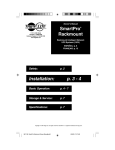
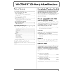
autoTWO
Automatic Mixer
Operation Manual
Biamp Systems | 9300 S.W. Gemini Drive | Beaverton, OR | 97008 | USA | +1.503.641.7287 | www.biamp.com
TABLE OF CONTENTS
Front Panel
pg. 2
Rear Panel
pg. 3
Logic Outputs
pgs. 4 & 5
Specifications & Block Diagram
pg. 6
Warranty
pg. 7
August, 2009
autoTWO
INTRODUCTION
The autoTWO Automatic Mixer is affordable, extremely versatile, and easy to use. Features include NOM attenuation, adaptive
threshold sensing, speech-frequency filtering, manual priority override, selectable channel-off attenuation, and selectable last mic
hold. The autoTWO is covered by a five-year warranty.
autoTWO features include:
♦ eight balanced mic/line inputs on plug-in barrier connectors
♦ trim, pad, level, & combined active/peak indicator per channel
♦ channel 1 manual ‘override’ via external contact-closure
♦ channel 8 ‘mix-minus’ assign & ‘ducking’ via channels 1~7
♦ balanced main & aux outputs on plug-in barrier connectors
♦ selectable last mic on, hpf, automix, & 48V phantom power
♦ selectable automix channel-off attenuation (-12dB or -40dB)
♦ pre/post automix assignment to main, aux, & direct outputs
♦ options selectable via external switches (no internal jumpers)
♦ logic outputs from channels for switching of external circuits
♦ Adaptive Threshold Sensing minimizes false gate triggering
♦ Speech-Frequency Filter minimizes false gating due to noise
♦ 6dB of hysteresis reduces gate ‘flutter’ when near threshold
♦ ‘stacking’ of two units to expand system input capability
♦ incorporates AES recommended grounding practices
♦
marked and UL / C-UL listed power source
♦ covered by Biamp Systems' five-year warranty
1
FRONT PANEL
Active Indicator (Channels 1~8): These dual-color LEDs provide
indication of two channel functions: channel active & peak level.
When a channel is assigned for automixing (gated) operation, the
Active indicator will light green whenever the channel is active
(on). NOTE: The Active indicator does not light green on a
channel assigned for manual (ungated) operation. See Channel
DIP Switches on next page. The Active indicator will also light red
whenever channel signal levels reach +10dB (8dB below clipping).
Use this feature to aid in adjusting the Trim controls (see below).
Release: This control adjusts the length of time that any channel
remains active (on) after signal level has dropped below threshold.
Release Time is adjustable from 150 milliseconds to 4 seconds.
Since channels activate very quickly (4 milliseconds Attack Time),
precise adjustment of Release Time may not be critical. However,
when using Logic Outputs to control external switching circuits
(such as cameras), moderate Release Time settings may provide
more appropriate timing (see Logic Outputs on next page).
Master: This control adjusts the level of overall signal sent to the
Main Output. The Main Output level is also affected by automatic
NOM attenuation, which reduces the output level by 3dB for each
doubling of active (gated) channels. Optimum Master settings are
near the 12 o’clock position (unity gain) or below.
Trim (Channels 1~8): These controls adjust the channel gain
(0~60dB) to compensate for different input signal levels. For best
performance, adjust these controls so the channel Active indictors
flash red (+10dB) on occasional peaks. NOTE: Accurate Trim
control settings are essential prior to Threshold adjustment (see
Threshold below). Once Threshold has been set, individual
channel sensitivities may be fine-tuned using the Trim controls. If
input signals exceed normal operating range of the Trim controls,
assign the Pad switch (see DIP switches on next page).
Aux: This control adjusts the level of overall signal sent to the Aux
Output. The Aux Output may be assigned either ungated (pre) or
gated (post) signals from the channels (see Master DIP Switches
on next page). NOTE: Unlike the Main Output, The Aux Output
does not provide automatic NOM attenuation.
Level (Channels 1~8): These controls adjust the amount of signal
sent from the individual input channels to the mixer output section.
Optimum Level setting is near the 12 o'clock position (unity gain).
-20 Indicator: This dual-color LED provides indication of both
signal present & peak level at the Main Output. This indicator will
light green when (internal) signal levels reach -20dB (signal
present). This same indicator will light red when (internal) signal
levels reach +10dB (8dB below clipping). Use this feature to aid in
adjusting the Master control. For best performance, adjust the
Master control so the -20 indictor flashes red (+10dB) only on
occasional peaks in signal level.
Threshold: This control adjusts the minimum signal level
(threshold) at which channels will become active (gate on). The
Threshold circuit also has 6dB of hysteresis, which allows a
channel to stay open until the signal level drops below the
threshold by 6dB. This hysteresis reduces the tendency for a
channel to ‘flutter’ on & off when it detects a signal that is right at
the threshold level. Because of the hysteresis, different threshold
settings will be arrived at depending on how you adjust this control.
If Threshold is set fully clockwise, then turned counter-clockwise
until all channels are easily activated by normal signal levels, the
threshold will be as high above ambient noise as possible. If
Threshold is set counter-clockwise, then turned clockwise until no
channels are activated by ambient noise, the threshold will allow
for greatest channel sensitivity. The threshold is further controlled
by Adaptive Threshold Sensing (ATS). ATS monitors signal from
active channels and automatically adjusts the threshold to prevent
false activation of other channels. NOTE: Accurate Trim control
settings are essential prior to Threshold adjustment. Once
Threshold has been set, individual channel sensitivities may be
fine-tuned using the Trim controls.
On Indicator: When the Power Cord is plugged in, and power is
applied to the autoTWO, the red On indicator remains lit.
2
REAR PANEL
Stack In: These plug-in barrier strip terminals provide a balanced
line-level Stack In to the mixer. Signal entering here is combined
with signals from the input channels, and is then sent to the Main
Output section. When using multiple autoTWO mixers within a
system, connect Main Output of one mixer to Stack In of the next
mixer, and so forth. All mixers except the final autoTWO should be
assigned as ‘slaves’ (see Master DIP Switches below). For
balanced connection, wire high (+), low (-), and ground (d). For
unbalanced connection, wire high (+) and ground to both (d) & (-).
DC Power Cord: The included power supply module provides 24
Volt DC power to the mixer. It is connected to the DC Power Jack
on the rear side of the mixer. To ensure compatibility, only use a
Biamp Systems supplied power supply.
Logic Outputs: This 9-pin Sub-D (male) connector provides logic
outputs from the eight channels, plus a common ground. When a
channel becomes active, the associated logic output turns on.
Logic Outputs are used to control external circuits for switching
speakers, cameras, or indicators (see Logic Outputs on pg. 4).
Inputs & Direct Outputs (Channels 1~8): These plug-in barrier
strip terminals provide the balanced mic/line Inputs to the mixer.
For balanced connection, wire high (+), low (-), and ground (d).
For unbalanced connection, wire high (+) and ground to both (d) &
(-). Phantom power (+48VDC) is available (see DIP Switches
below). Unbalanced 'pre-fader' Direct Outputs are available on
Channels 1~8, using the (d. out) & (d) terminals.
Expansion: This 6-pin Modular jack is for connection of a second
autoTWO mixer to add system inputs. When using two autoTWO
mixers in a system, it is necessary for the mixers to share
information regarding active channels. This information allows the
mixers to properly perform NOM Attenuation & Adaptive Threshold
Sensing. This connection requires a single Modular cable
(provided). The information shared is processed primarily by the
‘master’ autoTWO. To prevent system errors, the second
autoTWO mixer should be assigned as ‘slave’ (see Master DIP
Switches below). Channel 1 override can be achieved by shorting
pins 3 & 6 (see Logic Outputs on pg. 4).
Master DIP Switches: These switches assign functions to the
mixer as a whole (when pushed up). Slave assigns the mixer as
an expander to a ‘master’ mixer. -12dB selects -12dB channel-off
attenuation (instead of -40dB). HP Filter assigns a high-pass filter
of 6dB/octave @ 170Hz. Last Mic causes the most recently active
channel to remain on. Aux Post assigns post-gate/level channel
signals to the Aux Output (instead of pre-gate/level signals).
Main Output: These plug-in barrier strip terminals provide the
balanced line-level Main Output from the mixer. For balanced
connection, wire high (+), low (-), and ground (d). For unbalanced
connection, wire high (+) and ground (d), leaving (-) unconnected.
Signal level will be reduced by 6dB when output is unbalanced.
Main Output level is affected by the front panel Master control, as
well as by automatic NOM Attenuation, which reduces the output
level by 3dB for each doubling of active (gated) channels.
DIP Switches (Channels 1~8): These switches assign functions
to the individual channels (when pushed up). Pad attenuates input
signal -18dB (line input). Ungated turns channel on (defeats gate).
Phantom turns on +48V phantom power (for condenser mics).
Duck Ch 8 (Channels 1~7 only) assigns channel signal to activate
-12dB attenuation on Channel 8 (ducking). Aux Off (Channel 8
only) removes Channel 8 signal from Aux Output (mix-minus).
D. Out Pre assigns pre-gate signal to channel direct output (d.
out), instead of post-gate signal.
Aux Output: These plug-in barrier strip terminals provide the
balanced line-level Aux Output from the mixer. For balanced
connection, wire high (+), low (-), and ground (d). For unbalanced
connection, wire high (+) and ground (d), leaving (-) unconnected.
Signal level will be reduced by 6dB when output is unbalanced.
Aux Output level is affected by the front panel Aux control, but not
by automatic NOM Attenuation.
3
LOGIC OUTPUTS
The autoTWO provides eight logic outputs on a rear panel 9-pin Subminiature D (male) connector. Logic Outputs can be used to control
external switching circuits for speakers, cameras, indicators, etc. The autoTWO Logic Outputs are most often used, in conjunction with
external relays, to turn off specific speakers when nearby microphones are active (reducing feedback problems). For example, if a speaker
is located directly above microphone #1, the Logic Output for Channel 1 of the autoTWO can be used to turn off that speaker relay when
microphone #1 is active (see diagram on next page). The Logic Outputs can also be combined (wired in parallel) to control a single circuit.
For example, a speaker relay could be turned off when either microphone #1 or microphone #2 is active. In addition to speaker relays, the
autoTWO Logic Outputs may be used to control external indicator lights (see diagram on next page). Another common application for
Logic Outputs is to control video cameras. Different cameras could be activated depending upon which microphone (or group of
microphones) is currently active. Cameras can be selected using a video switcher and/or ‘pan/tilt/zoom’ camera presets. The Logic
Outputs may also be used in conjunction with the Expansion jack (pin 6 & pin 3) to perform ‘automatic priority’, which allows all other
channels to be muted whenever the Channel 1 microphone is active (see diagram on next page). The Logic Output (pin 1) & ground (pin
9) terminals for the Channel 1 ‘priority’ microphone are wired to pin 6 & pin 3 respectively of the Expansion jack. A switch or contactclosure may instead be used, for manual priority override.
The autoTWO Logic Outputs are ‘open collector’ outputs. Each Logic Output is an NPN transistor with the collector being the output and
the emitter being ground (see diagram on next page). When a Logic Output is turned on, the transistor provides a path for DC current to
flow. The Logic Outputs do not provide any voltage or current. They act only as switches (with a common ground return). To activate
external relays, an external power supply must be used (see diagram on next page). The Logic Output transistors are rated up to a
maximum of 24 VDC and 50 mA per output (24 volt relay coils maximum). However, +12 Volts DC is sufficient power for most
applications. When using the Logic Outputs to control relays, protection diodes must be used to suppress high voltage transients that are
generated when the relays turn off (see diagram on next page). Any of the 1N4004 family of diodes (1N4001, 1N4002, 1N4003, 1N4004,
1N4005, 1N4006, 1N4007, or equivalent) will provide proper protection. When a Logic Output goes on, the associated relay may be wired
to perform on, off, or ’A/B’ switching functions. To use logic ‘on’ to turn on (or activate) a device, wire across the ‘normally open’ relay
contacts, in series with the device (or control voltage source). To use logic ‘on’ to select between ‘A’ or ‘B’ signals (inputs or outputs), wire
one signal to the ‘normally closed’ relay terminal and the other signal to the ‘normally open’ relay terminal, with the common relay terminal
providing the feed (input or output).
The 9-pin Sub-D connector used for the autoTWO Logic Outputs is the same type of connector used for RS-232 communications ports on
IBM compatible computers. A cable may be created by simply wiring to the proper pins of a female 9-pin Sub-D cable-end connector.
1
2
6
3
7
4
8
5
9
logic outputs
logic out
channel 1
channel 2
channel 3
channel 4
channel 5
channel 6
channel 7
channel 8
ground
4
pin number
pin #1
pin #2
pin #3
pin #4
pin #5
pin #6
pin #7
pin #8
pin #9
5 4
3 2
1
9 8
7 6
9-pin cable-end
LOGIC OUTPUTS
Logic/Relay circuit
autoTWO
Pin #1
+12 Volts DC
Power Supply
−
+
12V Relay
Contacts
normally closed
common
normally open
Logic Output #1
1N4004
Diode
Coil
Pin #9
Logic Outputs controlling indicators
autoTWO
Pin #1
+12 Volts DC
Power Supply
−
+
Indicator Panel
1.2k ohms
Logic Output #1
LED
Pin #9
Channel 1 ‘automatic’ (logic output) or ‘manual’ (external switch) override of Channels 2~8
6
3
external
switch
1
9
ground
expansion
logic outputs
5
SPECIFICATIONS & BLOCK DIAGRAM
6
WARRANTY
BIAMP SYSTEMS IS PLEASED TO EXTEND THE FOLLOWING 5-YEAR LIMITED WARRANTY TO THE
ORIGINAL PURCHASER OF THE PROFESSIONAL SOUND EQUIPMENT DESCRIBED IN THIS MANUAL
1. BIAMP Systems warrants to the original purchaser of new
products that the product will be free from defects in material
and workmanship for a period of 5 YEARS from the date of
purchase from an authorized BIAMP Systems dealer, subject to
the terms and conditions set forth below.
2. If you notify BIAMP during the warranty period that a BIAMP
Systems product fails to comply with the warranty, BIAMP
Systems will repair or replace, at BIAMP Systems' option, the
nonconforming product. As a condition to receiving the benefits
of this warranty, you must provide BIAMP Systems with
documentation that establishes that you were the original
purchaser of the products. Such evidence may consist of your
sales receipt from an authorized BIAMP Systems dealer.
Transportation and insurance charges to and from the BIAMP
Systems factory for warranty service shall be your responsibility.
3. This warranty will be VOID if the serial number has been
removed or defaced; or if the product has been altered,
subjected to damage, abuse or rental usage, repaired by any
person not authorized by BIAMP Systems to make repairs; or
installed in any manner that does not comply with BIAMP
Systems' recommendations.
4. Electro-mechanical fans, electrolytic capacitors, and normal
wear and tear of items such as paint, knobs, handles, and
covers are not covered under this warranty.
5.
THIS WARRANTY IS IN LIEU OF ALL OTHER
WARRANTIES, EXPRESS OR IMPLIED. BIAMP SYSTEMS
DISCLAIMS ALL OTHER WARRANTIES, EXPRESS OR
IMPLIED, INCLUDING, BUT NOT LIMITED TO, IMPLIED
WARRANTIES OF MERCHANTABILITY AND FITNESS FOR A
PARTICULAR PURPOSE.
6. The remedies set forth herein shall be the purchaser's sole
and exclusive remedies with respect to any defective product.
7. No agent, employee, distributor or dealer of Biamp Systems
is authorized to modify this warranty or to make additional
warranties on behalf of Biamp Systems.
statements,
representations or warranties made by any dealer do not
constitute warranties by Biamp Systems. Biamp Systems shall
not be responsible or liable for any statement, representation or
warranty made by any dealer or other person.
8. No action for breach of this warranty may be commenced
more than one year after the expiration of this warranty.
9. BIAMP SYSTEMS SHALL NOT BE LIABLE FOR SPECIAL,
INDIRECT, INCIDENTAL, OR CONSEQUENTIAL DAMAGES,
INCLUDING LOST PROFITS OR LOSS OF USE ARISING
OUT OF THE PURCHASE, SALE, OR USE OF THE
PRODUCTS, EVEN IF BIAMP SYSTEMS WAS ADVISED OF
THE POSSIBILITY OF SUCH DAMAGES.
Biamp Systems
9300 S.W. Gemini Drive
Beaverton, Oregon 97008
(503) 641-7287
585.0236.90B
DoC AUT201003
EC Declaration of Conformity
Biamp Systems Corporation, as manufacturer having sole responsibility, hereby
declares that the following described product complies with the applicable provisions of
the DIRECTIVES below except as noted herein. Any alterations to the product not
agreed upon and directed by Biamp Systems Corporation will invalidate this declaration.
Product Model:
autoTWO
Product Description:
Automatic Mic/Line Mixer
Applicable EC Directives:
Applicable Harmonized Standards:
LVD Directive (2006/95/EC)
Safety
EN 60065:2002
EMC Directive (2004/108/EC)
Emissions
Immunity
EN 55103-1:1996, Environment E2
EN 55103-2:1996
Special Considerations for Product Environment or Compliance:
Use only Biamp Systems supplied 24 VDC External Power Supply Adaptor.
Shielded cabling must be used for system connections.
Technical Construction File, Location and Contact:
Biamp Systems, Inc.
9300 S.W. Gemini Drive
Beaverton, OR USA 97008
phone:
fax:
e-mail:
Authorized Representative:
Larry Copley, Compliance Engineer
Authorized Signature:
Issued:
March, 2010 (503) 641.7287
(503) 626.0281
[email protected]