1
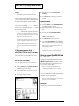
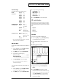
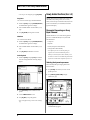
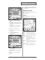
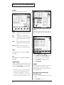
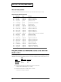
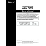
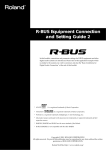
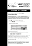
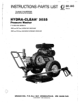
VM-C7200/C7100 Newly Added Functions
Table of Contents
Newly Added Functions (Ver.1.1)
Newly Added Functions (Ver.1.1).................................1
Following functions have been added to the system for the
VM-C7200/C7100 (V-Mixing Console; Ver.1.1 or later).
When you turn on the power of the VM-C7200/7100, current
system version number of your VM-C7200/C7100 will be
appeared in the display.
How to connect the ADA-7000
and the AE-7000 series ..................................................1
If the system software of the VMC7200/C7100 is
Ver.1.10 or later .................................................................................2
How to connect the AE-7000
and the VM-7000 series .................................................3
If the system software of the VM-C7200/C7100 is
Ver.1.10 or later .................................................................................4
How to connect the VSR-880
and the VM-7000 series .................................................4
MTR control functions .....................................................................5
Newly Added Functions (Ver.1.5).................................6
Dynamics Processing on Every Input Channel.........6
Selecting the dynamics processor...................................................6
Editing Dynamics Processor ...........................................................7
Using Libraries ..................................................................................8
Scene ...................................................................................................8
Automix .............................................................................................8
Others ..............................................................................9
Effects Bypass Switch .......................................................................9
INPLACE SOLO ...............................................................................9
SOLO SW Flashing ...........................................................................9
Monitor Source Select.......................................................................9
Libraries Newly Added ..............................................10
PROJECTs, SCENEs and TEMPLATEs
created on the VM-7000 Ver.1.1 or 1.5 ........................10
MEMO..............................................................................11
How to connect the ADA-7000
and the AE-7000 series
To connect the VM-7200/7100 and the ADA-7000 via R-BUS,
VM-24E I/O Expansion Board (sold separately) is needed.
By installing the VM-24E to the VM-7200/7100 processor,
you can connect up to three ADA-7000’s.
* Refer to VM-7200/7100 Owner’s Manual p. 14 “Installing RBUS (RMDB2) Connectors (VM-24E).”
Connection
Connect the VM-7200/7100 and the ADA-7000 with the RBUS cable attached in the ADA-7000 box.
* Refer to ADA-7000 Owner’s Manual p. 9 “An Example of
Connection.”
Booting up
Turn the power on the ADA-7000 first, then the VM-7200/
7100 processor, and finally the VM-C7200/C7100 console.
Clock source setting
If clock source has not been set, noise may be generated from
the audio output on the ADA-7000 and the VM-7000. While
setting the clock source, please turn down the master and
monitor level, and turn up again after the setting is finished.
Set the sampling clock on the ADA-7000 and the VM-7000 as
follows.
Clock Source on the ADA-7000
connected to the R-BUS (1–8): ...................................R-BUS
Clock Source on the ADA-7000
connected to the R-BUS (9–16): .................................R-BUS
Clock Source on the ADA-7000
connected to the R-BUS (17–24): ...............................R-BUS
Master clock on the VM-7000: ................................ INTERNAL
1
VM-C7200/C7100 Newly Added Functions
ADA-7000 setting
fig.ada_70
Check if the clock source on the ADA-7000 is set to R-BUS.
When the ADA-7000 is booted up, the clock source is set to
R-BUS. If you connect multiple ADA-7000, set the clock
source on all ADA-7000 to R-BUS.
* Refer to ADA-7000 Owner’s Manual p. 6 “Clock source.”
VM-7000 setting
Set the master clock of the VM-7200/7100 to INTERNAL as
follows.
1. Hold down [SHIFT], and press [SYSTEM] (PROJECT).
2. Press [DOWN] cursor, then press [F1] (DIGITAL I/O).
3. Select “WORD CLOCK SOURCE,” and set it to
“INTERNAL” with V1 knob, then press [F1] (SET) to
activate the result.
* Refer to the VM-C7200/C7100 Owner’s Manual p. 32
“Checking the overall system.”
* If you set the clock source differently, please refer to the ADA7000 Owner’s Manual p. 6 “Clock source” and the VMC7200/C7100 Owner’s Manual p. 31 “About Digital
Connections and the Master Clock.”
* If the system of the VM-C7200/C7100 is version 1.0 or earlier,
“DIF-AT” is displayed in the R-BUS CONFIG page even
though the ADA-7000 is connected. This cause no problem for
the operation. With the VM-C7200/C7100 version 1.10 or
later, you can set the ADA-7000 with the R-BUS CONFIG
page.
* VM-7000 is not accommodated with 96.0 kHz sample rate.
96.0 kHz sample rate capability on the ADA-7000 is for the
future devices.
* If the above menu does not appear in the “R-BUS 1(/2/3)”
page of “SYSTEM CONFIG” menu, please turn off the power
of whole system, check the R-BUS connection and turn on
again.
4. Select a desired source with V1 knob (CLOCK
SOURCE).
5. Press [F1] (SET) and the clock source you selected is
activated.
6. If you select “INTERNAL” for the clock source, set the
sampling rate with V3 knob (SAMPLING RATE).
7. Press [F3] (SET) and the sampling rate you selected is
activated.
Front Panel Control
In the R-BUS 1(/2/3) page, you can prohibit the ADA-7000’s
panel operation.
1. Hold down [SHIFT], and press [SYSTEM] (PROJECT).
SYSTEM menu appears in the display.
If the system software of the
VM-C7200/C7100 is Ver.1.10 or later
2. Select “SYSTEM CONFIG” and go to “R-BUS 1(/2/3)”
page.
If the system software of the VM-C7200/C7100 is version
1.10 or later, following functions are supported.
3. Press [F5] (FRONT PANEL CONTROL).
ADA-7000 Clock source setting
Highlight ON:
Panel control enabled
Normal ON:
Panel control invalid
You can set up the ADA-7000’s clock source with the
VM-C7200/C7100 console.
Remote control of the gain and phantom
power
1. Hold down [SHIFT], and press [SYSTEM] (PROJECT).
SYSTEM menu appears in the display.
You can control the gain setting and phantom power on/off
with the VM-C7200/C7100 console.
2. Select “SYSTEM CONFIG” and go to “R-BUS 1(/2/3)”
page.
1. Press [MULTI IN 1-24] in the “SECTION” block.
3. Following page appears in the display.
2
2. Press [PREAMP GAIN] in the “PARAM VIEW on Fader”
block.
VM-C7200/C7100 Newly Added Functions
3. Control the gain and phantom power on/off in the same
manner as for the [INPUT].
* PAD on the ADA-7000 is automatically switched on/off
according to the gain setting.
How to connect the AE-7000 and
the VM-7000 series
To connect the VM-7200/7100 and the AE-7000 via R-BUS,
VM-24E I/O Expansion Board (sold separately) is needed.
By installing the VM-24E to the VM-7200/7100 processor,
you can connect up to three AE-7000’s.
* Refer to VM-7200/7100 Owner’s Manual p. 14 “Installing
R-BUS (RMDB2) Connectors (VM-24E).”
AE-7000 does not have the sample rate converter.
All the digital signal input into multiple AE-7000’s connected
to the VM-7200/7100 must be synchronized with sample
clock accuracy. To synchronize two digital devices with
sample clock accuracy, you need to use word clock signal or
digital audio signal.
• If AES/EBU input on the AE-7000 is not used, and only
output is used
• Set the sampling clock on the AE-7000 and the VM-7000
as follows.
Clock Source on the AE-7000
connected to the R-BUS (1–8): ...................................R-BUS
Clock Source on the AE-7000
connected to the R-BUS (9–16): .................................R-BUS
Clock Source on the AE-7000
connected to the R-BUS (17–24): ...............................R-BUS
Master clock on the VM-7000: ................................ INTERNAL
==AE-7000 setting==
Check if the clock source on the AE-7000 is set to R-BUS.
When the AE-7000 is booted up, the clock source is set to RBUS. If you connect multiple AE-7000’s, set the clock source
on all AE-7000’s to R-BUS.
* Refer to AE-7000 Owner’s Manual p. 5 “Clock source Select.”
==VM-7000 setting==
Connection
Connect the VM-7200/7100 and the AE-7000 with the R-BUS
cable attached in the AE-7000 box.
* Refer to the AE-7000 Owner’s Manual p. 8 “An Example of
Connection.”
Booting up
AE-7000 works with the power supplied via R-BUS. Turn the
power on the VM-7200/7100 processor, and the power is
supplied to the AE-7000. Then finally turn on the
VM-C7200/C7100 console.
Set the master clock of the VM-7200/7100 to INTERNAL as
follows.
1. Hold down [SHIFT], and press [SYSTEM] (PROJECT).
2. Press [DOWN] cursor, then press [F1] (DIGITAL I/O).
3. Select “WORD CLOCK SOURCE,” and set it to
INTERNAL with V1 knob, then press [F1] (SET) to
activate the result.
* Refer to VM-C7200/C7100 Owner’s Manual p. 32 “Checking
the overall system.”
Example 2
Clock source setting
• If AES/EBU device outputs the word clock
If clock source has not been set, noise may be generated from
the audio output on the AE-7000 and the VM-7000. While
setting the clock source, please turn down the master and
monitor level, and turn up again after the setting is finished.
Connect the word clock of the AES/EBU device to the
VM-7200/7100.
Clock source setting varies depending on the AES/EBU
devices connected to the AE-7000 and other condition. Please
Clock Source on the AE-7000
connected to the R-BUS (1–8): ...................................R-BUS
set as follows.
Clock Source on the AE-7000
connected to the R-BUS (9–16): .................................R-BUS
Example 1
Clock Source on the AE-7000
connected to the R-BUS (17–24): ...............................R-BUS
• If AES/EBU device is synchronized to the word clock
from the VM-7000, or to the AES/EBU signal from the
AE-7000
Master clock on the VM-7000: ......................... WORD CLOCK
3
VM-C7200/C7100 Newly Added Functions
Example 3
• If AES/EBU device does not output the word clock
Connect the output of the AES/EBU device to the INPUT A
of the 1st AE-7000. In this case, please set the clock source on
the AE-7000, and then the master clock on the VM-7000.
Clock source on the 1st AE-7000: ............................... INPUT A
Clock source on the 2nd and later AE-7000’s:................R-BUS
Master clock on the VM-7000:
...........................R-BUS which the 1st AE-7000 is connected to
* Please refer to AE-7000 Owner’s Manual p. 5 “Clock source
select” and VM-C7200/C7100 Owner’s Manual p. 31 “About
Digital Connections and the Master Clock.”
* If the system of the VM-C7200/C7100 is version 1.0 or earlier,
“DIF-AT” is displayed in the R-BUS CONFIG page even
though the AE-7000 is connected. This cause no problem for
the operation. With the VM-C7200/C7100 version 1.10 or
later, you can set the AE-7000 with the R-BUS CONFIG
page.
If the system software of the
VM-C7200/C7100 is Ver.1.10 or later
If the system software of the VM-C7200/C7100 is version
1.10 or later, following functions are supported.
AE-7000 Clock source setting
You can set up the AE-7000’s clock source with the VMC7200/C7100 console.
1. Hold down [SHIFT], and press [SYSTEM] (PROJECT).
SYSTEM menu appears in the display.
2. Select “SYSTEM CONFIG” and go to “R-BUS (1/2/3)”
page.
3. Following page appears in the display.
fig.ae_70
4. Select a desired source with V1 knob (CLOCK
SOURCE).
5. Press [F1] (SET) and the clock source you selected is
activated.
Digital Out settings
1. Hold down [SHIFT], and press [SYSTEM] (PROJECT).
SYSTEM menu appears in the display.
2. Select “SYSTEM CONFIG” and go to “R-BUS (1/2/3)”
page.
3. Select the TYPE with V3 knob [TYPE1/TYPE2].
TYPE1: Broadcasting studio
TYPE2: Consumer digital audio
4. Press [F3] (SET) and the setting is activated.
5. If you set [F4] (COPY PROTECT) to ON, SCMS turns on
and you can restrict the digital copy of the output signal.
* If the TYPE is set to TYPE1 (Broadcasting studio), COPY
PROTECT setting is invalid.
* If digital signal is connected into the digital input of the
AE-7000, status is shown in the middle of the display.
How to connect the VSR-880 and
the VM-7000 series
To connect the VSR-880 and the VM-7200/7100 via R-BUS,
VM-24E I/O Expansion Board (sold separately) is needed.
By installing the VM-24E to the VM-7200/7100 processor,
you can connect up to three VSR-880’s.
* Refer to the VM-7200/7100 Owner’s Manual p. 14
“Installing R-BUS (RMDB2) Connectors (VM-24E).”
Connection
Connect the VSR-880 and the VM-7200/7100 with the R-BUS
cable (RBC-1 or RBC-05; separately sold).
* Refer to the VSR-880 Owner’s Manual p. 140 “Synchronized
operation of two or more VSR-880 units.”
Booting up
Turn the power on the VSR-880 first, then VM-7100/7200
processor, and finally VM-C7100/7200 console.
4
VM-C7200/C7100 Newly Added Functions
VSR-880 Settings
3. Set up the following in the SETUP page.
Set the some parameters of the VSR-880 as follows.
SYNC MASTER:
INT
MASTER
Direct Out:
On
MMC CONTROL:
ON
INPUT MIXER
IN1 Input:
R-BUS
MMC MASTER:
INT
IN2 Input:
R-BUS
MACHINE TYPE:
IN3 Input:
R-BUS
HD
IN4 Input:
R-BUS
IN5 Input:
R-BUS
IN6 Input:
R-BUS
IN7 Input:
R-BUS
IN8 Input:
R-BUS
SYSTEM:System PRM
MasterClk:
R-BUS
SYSTEM:MIDI PRM
MIDIThr:
Out (1st unit),
Thru (2nd unit)
SYSTEM:Sync/Tempo
4. Press [LEVEL METER] to return to initial display.
MTR control functions
If the VSR-880 is connected to the VM-7100/7200 via R-BUS,
following functions are supported, in addition to the existing
MTR control functions such as transport, locator and channel
status.
SysEx.Rx:
On
• Song Select
SysEx.Tx:
On (1st unit)
• Song Store
MMC:
MASTER (1st unit),
• Shutdown
SLAVE (2nd & 3rd units)
• Scrub playback
Sync Source: EXT
InSel:
R-BUS (1st unit),
MIDI (2nd & 3rd units)
Song Select
Gen.:
MTC (1st unit)
You can select a song from the VSR-880 hard disk.
MTC Type:
30
1. Hold down [SHIFT], and press [SYSTEM] (PROJECT).
The SYSTEM menu appears in the display.
* Refer to the VSR-880 Owner’s Manual p. 140 “Synchronized
operation of two or more VSR-880 units.”
VM-7000 settings
Set the master clock of the VM-7200/7100 to “INTERNAL” as
follows.
2. Select “SYSTEM CONFIG” and then “R-BUS (1/2/3)”
page.
3. Following appears in the display.
fig.vsr1_70
1. Hold down [SHIFT], and press [SYSTEM] (PROJECT).
The SYSTEM menu appears in the display.
2. Press [DOWN] cursor, then press [F1] (DIGITAL I/O).
3. Set up the following in the SETUP page.
WORD CLOCK SOURCE:...........................................INTERNAL
INTERNAL SAMPLING RATE:
......... in accordance with the sampling rate of the VSR-880 song
4. Press [LEVEL METER] to return to initial display.
* Refer to the VM-C7200/C7100 Owner’s Manual p. 32
“Checking the overall system.”
4. List of the songs in the VSR-880 hard disk appears.
Also, set the SYNC MASTER settings of the VM-7200/7100
as follows.
1. Hold down [SHIFT], and press [SYSTEM] (PROJECT).
The SYSTEM menu appears in the display.
2. Press [DOWN] cursor, then press [F3] (SYNC CLOCK).
5. Highlight a desired song with V1 knob (SELECT
SONG).
6. Press [F1] (SELECT) and Song Select is executed.
* If multiple VSR-880 are connected to the R-BUS 1/2/3, a song
of the same number in each VSR-880 can be selected at once by
pressing [F2] (SELECT ALL). It is convenient when you
construct 16-track system with two VSR-880, or 24-track
system with three VSR-880.
5
VM-C7200/C7100 Newly Added Functions
* Latest song list can be displayed by pressing [F6] (SCAN).
Song Store
You can store the current song to the VSR-880 hard disk.
1. Hold down [SHIFT], and press [SYSTEM (PROJECT).
The SYSTEM menu appears in the display.
2. Select “SYSTEM CONFIG” and then “R-BUS (1/2/3)”
page.
3. Press [F3] (STORE) and Song Store is executed.
Shutdown
You can shut down the VSR-880.
Newly Added Functions (Ver.1.5)
Following functions have been added to the system for the
VM-C7200/C7100 (V-Mixing Console; Ver.1.5 or later).
When you turn on the power of the VM-C7200/7100, current
system version number of your VM-C7200/C7100 will be
appeared in the display.
Dynamics Processing on Every
Input Channel
With the VM-7000 Ver.1.5, one of the following dynamics
processor is available individually on every INPUT and
MULTI IN channel.
1. Hold down [SHIFT], and press [SYSTEM (PROJECT).
The SYSTEM menu appears in the display.
• Compressor
2. Select “SYSTEM CONFIG” and then “R-BUS (1/2/3)”
page.
• Limiter (Compressor with RATIO:INF)
3. Press [F4] (SHUT) and Shutdown is executed.
* These dynamics processors are achieved by sharing the
algorithm resources with the Feedback Delay (Owner’s
Manual p. 81) and the Equalizer (Owner’s Manual p. 78) on
the channel. You cannot use the Feedback Delay and LO-MID
Equalizer on the channel which the dynamics processor is on.
Scrub Playback
1. Hold down [SHIFT], and press [PLAY]. The VSR-880
turns into scrub playback mode. Following dialogue
appears.
fig.vsr2_70
• Expander
• Gate (Expander with RATIO:INF)
Selecting the dynamics processor
Select a desired dynamics processing algorithm on the
channel as follows.
1. Press [CH EDIT] of the channel you wish to use the
dynamics processor.
2. Press [PAGE UP], [PAGE DOWN] to display
“DELAY/DY” page.
fig.01_70
2. Press [CH STATUS] of desired channel for scrub
preview.
3. Turn the TIME/VALUE dial to scrub.
4. Press [F6] (EXIT) to stop scrub playback.
* In the Scrub playback mode, you cannot switch the display
page.
3. Press [F5] (ALGORITHM DLY/DYN). SELECT
ALGORITHM dialog appears.
6
VM-C7200/C7100 Newly Added Functions
fig.03_70
6. Press [F1] (SET) to make the algorithm effective on the
channel. Dialog is closed and the edit page of the selected
algorithm appears.
Editing Dynamics Processor
By the dynamics algorithm you selected, contents of the edit
page in “DELAY/DY” vary.
Compressor
Compresses the total output signal when the input level
surpasses the threshold.
fig.04_70
4. Highlight the desired algorithm with V1 knob
(SELECT).
5. Press [F1] (SET) to make the algorithm effective on the
channel. Dialog is closed and the edit page of the selected
algorithm appears.
* If [F2] (ALL SET) is pressed instead of [F1 (SET)], same
selected algorithm is assigned to every channel.
Dynamics algorithm can also be selected as follows.
1. Press [CH EDIT] of the channel you wish to use the
dynamics processor.
2. Press [PAGE UP], [PAGE DOWN] to display
“DELAY/DY” page.
fig.03_70
[ON]
On/Off switch of the compressor
Level
Output signal level of the compressor
Thresh
Level at which the compressor starts working.
Ratio
Compression ratio to the input signal level
[AutoGain]
When on, total output level of the compressor
is automatically regulated.
Attack
Time how quickly the compressor starts
working when the input signal exceeds the
threshold level.
Release
Time how long the compressor works after the
input signal has fallen below the threshold
level.
Detect Time Delay time of the input signal into the
compressor. For more strict dynamics control.
3. Press CURSOR [UP], [DOWN] to move the cursor to the
top-center in the display.
4. Press [F6] (DLY/DYN). SELECT ALGORITHM dialog
appears.
5. Highlight the desired algorithm with V1 knob
(SELECT).
7
VM-C7200/C7100 Newly Added Functions
Expander
fig.06_70
Expanding the dynamic range with a certain ratio.
fig.05_70
Scene
[ON]
On/Off switch of the expander
Thresh
Threshold level at which the expander starts
working.
Ratio
Expanding ratio to the input signal level
Attack
Time how quickly the expander starts working
when the input signal exceeds the threshold
level.
Release
Time how long the expander works after the
input signal has fallen below the threshold
level.
Dynamics processors can be stored in the scene. Following
steps are to recall the dynamics processor setting with the
scene.
fig.07_70
Detect Time Delay time of the input signal into the
expander. For more strict dynamics control.
Limiter
Same editing parameters as Compressor except Ratio is
preset to INF.
Gate
Same editing parameters as EXPANDER except Ratio is
preset to INF.
Using Libraries
Libraries are available for the dynamics processors as well as
the existing Delay and EQ libraries (**). To use the Dynamics
Libraries, press [COPY/LIBRARY] in “DELAY/DY” page.
* Dynamics libraries are shared by Compressor and Expander
algorithms. Patch names of the algorithms which are not
currently selected are displayed with < >, and cannot be
loaded. In the user area of the libraries, you can overwrite and
save the current algorithm setting even on these < > patches.
1. Hold down [SHIFT], and press [SCENE].
2. Press [CURSOR UP] or [CUTSOR DOWN] to move the
cursor to the top row of ACTIVE PARAMETERS.
3. Press [F4] (DYNAMIC) to highlight “DYNAMIC.”
4. Press [LEVEL METER].
Automix
On/Off switch setting of the dynamics processors can be
stored with Automix. Please also refer to “Chapter 11
Recording/Playing Back Fader or Knob Actions (Automix)”
(Owner’s Manual p. 196–).
Recording On/Off switch setting of the
dynamics processors
1. Press any of the buttons in SECTION to select one of the
sections.
2. Press [AUTO-MIX] (indicator: red).
8
VM-C7200/C7100 Newly Added Functions
3. Press [AUTO-MIX] under CH STATUS.
INPLACE SOLO
4. Press the status buttons for the channel for which automixing is to be recorded to set it to the recording state
(indicator: red).
Function is modified when SOLO MODE (Owner’s Manual
p.107) is set to INPLACE as follows. When soloing INPUT or
MULTI IN, the effect inserted to FLEX BUS can be monitored
simultaneously. If SOLO mode is not “INPLACE,” function
is the same as the previous version.
5. Press [PAGE UP] or [PAGE DOWN] to display
“DELAY/DN” page.
6. Press [PLAY] to start recording auto-mixing. Every time
[F1] is pressed, dynamics processor switches on/off
alternately and the status is recorded in the auto-mix.
7. Press [STOP] to stop recording.
Editing On/Off switch setting of the dynamics
processors
To edit On/Off switch setting of the dynamics processors,
open “AUTO MIX EDIT” page (Owner’s Manual p.208), then
set “COMP SW” or “EXP SW” to be displayed with V2 knob
(PARAM).
1. When [SOLO] for INPUT or MULTI IN is pressed, only
INPUT and MULTI IN channels which are not soloed are
muted. (With the version 1.11 or before, Flex Buses are
also muted in this case.)
2. Flex Buses cannot be soloed. (With the version 1.11 or
before, Flex Busses can be soloed.)
SOLO SW Flashing
Any channel of INPUT or MULTI IN is soloed, SOLO
indicator of CH STATUS flashes to show SOLO is on.
Monitor Source Select
Others
Frequently assigned sources for the monitor are available on
[F2] – [F5] for quick setting.
Effects Bypass Switch
1. Press [SOURCE SELECT].
fig.09_70
Effects bypass switch is added in “EDIT” pages for Effects 1–
8 and Master Effects, to temporarily switch on/off the effect.
1. Press [EFFECTS1-8] or [SP MODELING(MASTER FX)].
2. Press [EDIT] of desired effect.
fig.08_70
2. Select a desired source among the following switches.
[F2] (DIG IN)
Input ch21/22 (DIGITAL IN is routed
as a default.)
[F3] (CONSOL) Input ch23/24 (CONSOLE IN is routed
as a default.)
3. Effect on/off switches every time [F6] (BYPASS) is
pressed. When “BYPASS” at the bottom right in the
display is highlighted, the signal is bypassed (effect is
temporarily turned off).
* Bypass switch cannot be stored in the scene. It will be cleared
when recalling the scene.
[F4] (MAIN)
MAIN OUT
[F5] (CUE)
CUE OUT
* [F2] switch always monitors the sources assigned to the input
ch21/22 and [F3] monitors the sources assigned ch23/24. If
you change the preset routing (DIGITAL IN to ch21/22 and
CONSOLE IN to ch23/24) with PATCH BAY, currently
assigned sources are monitored.
9
VM-C7200/C7100 Newly Added Functions
Libraries Newly Added
Following channel dynamics libraries have been added to the system for the VM-C7200/C7100 (Ver.1.1 or later).
Channel Dynamics Libraries (20 presets)
No.
Patch Name
Type
Comments
P000
Kick Comp
Compressor
Compression for Kick Drum
P001
Snare Comp
Compressor
Compression for Snare Drum
P002
Tom Expand
Expander
Expansion for TomTom
P003
Overhd Expand
Expander
Expansion for Drm Overhead Mics
P004
Hi Hat Expand
Expander
Expansion for HiHat
P005
BassGtrLimit
Compressor
Limiter for Electric Bass
P006
BassGtr Comp
Compressor
Compression for Electric Bass
P007
RockVoc Comp
Compressor
Compression for Rock Vocals
P008
Rap Voc Comp
Compressor
Compression for Rap Vocals
P009
SoftVoc Comp
Compressor
Compression for Ballad Vocals
P010
SmAmpGtrComp
Compressor
Compression for Electric Guitar with a small amplifier
P011
Kick Expand
Expander
Expansion for Kick Drum
P012
Snare Expand
Expander
Expansion for Snare Drum
P013
DrmMix Comp
Compressor
Compression for a Drum Mix
P014
Tmpt/SaxComp
Compressor
Compression for Trumpet or Sax
P015
BrassSecComp
Compressor
Compression for a Brass Section
P016
BrkbeatLimit
Compressor
Limiter for Breakbeat loops
P017
SynthPadComp
Compressor
Compression for Synth Pads
P018
AcoGtr Comp
Compressor
Compression for Acoustic Guitar
P019
JC Egtr Limit
Compressor
”Limiter for “”JC”” Electric Guitar”
PROJECTs, SCENEs and TEMPLATEs created on the VM-7000
Ver.1.1 or 1.5
In this VM-C7200/C7100 unit, system version 1.5 (or 1.1) is installed. On this new system, structure of the PROJECTs, SCENEs and
TEMPLATEs has been changed, so compatibility restriction occurs with the smart media saved with the older system version 1.0.
Load
Created
Ver.1.0 or earlier
Ver.1.1 or 1.5
Ver.1.0 or earlier
OK
OK (*1)
Ver.1.1 or 1.5
NG (*2)
OK
(*1) Load the data created with ver.1.0 or earlier into the system ver.1.1. and overwrite
→ OK (File on the smart media changes to ver.1.1 format.)
(*2) Load the data created with ver.1.1 into the system ver.1.0 or earlier
→ NO (If Macro for the display is registered.)
10
VM-C7200/C7100 Newly Added Functions
MEMO
11
VM-C7200/C7100 Newly Added Functions
MEMO
Copyright © 2000 ROLAND CORPORATION
All rights reserved. No part of this publication may be
reproduced in any form without the written permission
of ROLAND CORPORATION.
Roland International Website http://www.roland.co.jp/
40347578
12
’00-3-AE2-11TK