1
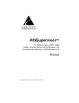
Universal Quick Install Guide
Quantum and Triton Boards
Use this guide to install Quantum boards and Triton class telephony boards,
including Triton VoIP, Triton Analog Extension, Triton Analog Trunk (LS and LS/
GS), Triton Resource, Triton T1/PRI, Triton T1/E1 PRI, and Triton 30-Party
MeetMe, all of which have common installation procedures.
MVIP Connector
MVIP BUS Termination Switch
Power Cable
Board Silhouette
All Triton PCI Family and Quantum Boards
Note:
In systems with over 12 boards installed, use the 10-connector side of the
ribbon cable on the short end and use the 12-connector side of the ribbon
cable on the long end. Starting with the innermost connectors, connect the
boards, leaving a minimum of 3 connectors hanging off each end.
Supported Board/Software Guidelines
Board
OE
4.5
Quantum
Triton Analog Extension
Triton Analog Extension B
Triton Analog Trunk-12
Triton Analog Trunk-8
Triton T1/PRI
Triton T1/E1 PRI
Triton VoIP-30
Triton VoIP-8
Triton Resource
Triton 30-Party MeetMe
Yes
Yes
No
Yes
No
Yes
Yes
Yes
Yes
Yes
No
OE/ACC/
OE/ACC/ OE/ACC/ACM/ OE/ACC/ACM/ ACC/ACM
ACM/HPBX ACM 5.0/ HPBX 5.0A
HPBX 5.0A
5.1
4.6
5.0A
Update 2 & 3 Update 4 & up
Yes
Yes
Yes
Yes
Yes
Yes
Yes
Yes
Yes
Yes
No
No
No
Yes
Yes
Yes
Yes
Yes
Yes
Yes
No
No
Yes
Yes
Yes
Yes
Yes
Yes
Yes
Yes
Yes
Yes
Yes
Yes
Yes
Yes
Yes
Yes
Yes
Yes
Yes
Yes
Yes
Yes
Yes
Yes
Yes
Yes
Yes
Yes
No
No
No
No
Yes
Installation Notes
• Observe proper board handling procedures (refer to AltiGen Field Alert #67).
• Pre-installation of boards is recommended over on-site installations.
• Although boards are factory tested prior to shipping, it is recommended that you
follow a burn-in period of approximately 12 hours minimum before an on-site
deployment.
• Always observe personal safety procedures.
• Persons performing the installation should observe proper grounding
requirements so as to prevent electrostatic discharge (ESD) damage to the
equipment.
• Do not remove boards from their protective anti-static bags until the boards are
ready to be installed.
• If your system has multiple T1/PRI or T1/E1 PRI boards, always use the board
connected to the CO as the MVIP clock reference. Ensure that your system is not
referenced to the T1 or T1/E1 PRI board that is not connected to the CO. This may
require changing the MVIP clock setting from automatic to manual, and selecting
the board number connected to the CO currently in service.
• (Triton Analog Only) The audio input and first extension share the same physical
port. The first extension port cannot be used as a physical extension when this
board is assigned as a music on hold input board. The audio input port is a 3.5mm
phone jack connector, with a 20k ohm impedance.
• 5.0A Update 2 (or later) software MUST be installed prior to installing the 8-port
Triton Analog Trunk board (ALTI-TTAT-8). If this hardware is installed prior to
the 5.0A Update 2 software, the system will hang/freeze during boot up every
time. To obtain the latest 5.0A update, download from the AltiGen Dealer web
site at https://dealer.altigen.com, or contact AltiGen Technical Support for more
information.
Connection Options
There are 3 connection options for connecting Quantum/Triton boards to trunks and
extensions:
1. 12 Ports Bridging Adapter
2. 66 Punch Down Block with 50-Pin Telco Female Connector
3. Patch Panel with 50-Pin Telco Female Connector
Installation Instructions
(It is assumed that the server operating system, AltiWare, and its corresponding
licenses are already installed.)
1. Ensure that the chassis power switch is in the OFF position and the power cord
is unplugged before removing the chassis cover.
2. Slide the board into the board guide on the chassis, then firmly seat the board into
the slot.
3. Screw the board down to the chassis for support.
4. Attach the MVIP cable so that the excess connectors are hanging off the board
on both ends. Firmly seat the MVIP cable connectors on all boards.
5. Close the Red MVIP bus termination switches on the boards at both ends (first
and last boards ONLY). All other boards should be set in the open position. Do
not have any board terminated in the middle of the MVIP bus, as this will cause
an MVIP bus clocking error.
6. Use a small screwdriver to configure the ID on the back of each board. Each
board has its own set of board IDs. It is recommended that you assign each board
a unique ID:
• Quantum: 0–F (ID “0” cannot be used in Windows 2000 server)
• Triton T1/PRI: 0–7 (only 0–5 is supported in OE 4.5 or above)
• Triton T1/E1 PRI: 0–7 (only 0–5 is supported in OE 4.5 or above)
• Triton Resource: 0–1
• Triton 30-Party: 0–F
• Triton VoIP: 0–F
• Triton Analog Extension (12 extensions): 0–F
• Triton Analog Trunk: 0–F
7. Install the AltiGen System Key and ground the server before plugging in the
power cord.
8. Boot the server and log on to Windows.
9. Stop services: In releases prior to 5.1, go to Windows Services, available from
Windows Control Panel, and stop “Switching Service COM Server” to stop all
related services. In release 5.1, from the Windows Start > Programs menu,
choose AltiWare ACC/ACM > Utilities > Start & Stop All AltiGen Services.
10. Wait a few minutes for the switching service to stop.
11. Run the MVIP Test Tool (called CT-Bus Test Tool in release 5.1). Go to
Start>Programs>AltiWare ACC/ACM>AltiWare Tools>MVIP Test Tool
to perform the MVIP test. (In 5.1, it’s Gateway Tools > CT-Bus Test Tool.)
12. If the test is successful, click Save Log and save the text file as
“MVIPTESTRESULTS.txt” on the desktop, then exit the test tool application.
13. If the test fails, check MVIP connections and troubleshoot accordingly. If there
are any failures, note the board(s) and use the following steps to troubleshoot the
MVIP connection: (System shutdown is not necessary for MVIP
troubleshooting unless replacing a board.)
• Remove the MVIP cable from all boards and check the MVIP connector on
the boards for bent or pushed down pins.
• Recheck ALL MVIP configurations, including re-seating the MVIP cable
and re-checking the MVIP bus termination switches for correct
termination.
• Run the MVIP/CT-Bus test again. If the test still fails, note the failing board
and replace it. Repeat installation procedures starting from Step 1. (Before
returning the defective board, contact AltiGen for an RMA number.)
14. If the board(s) have been properly installed, the newly installed boards will
appear in the Boards View window in AltiWare Administrator.
Installing Channel Service Unit (CSU) to the Triton T1
or T1/E1/PRI Board
1. Connect the CSU (Adtran model T1 CSU ACE used as an example) to the T1/
PRI or T1/E1PRI board using an RJ-48C or RJ-48X cable.
2. Connect the CSU to the network termination box using an RJ-48C or RJ-48X
cable.
AltiGen T1 Socket (RJ-48)
Pin 1=Receive Ring (INPUT)
Pin 2=Receive Tip (INPUT)
Pin 4=Transmit Ring (OUTPUT)
Pin 5=Transmit Tip (OUTPUT)
Refer to your CSU manufacturer’s manual for the proper pinout.
Technical Support
End users
Contact your authorized AltiGen Dealer.
Authorized AltiGen Dealers
Call AltiGen Technical Support at 510-252-9712
Submit a case on the authorized dealer web site: https://dealer.altigen.com
The following information will be required:
Dealer Name - ID# __________________________________________________
End User Name ____________________________________________________
Location __________________________________________________________
Credit Card (if required) __________________________ Expiration___________
Serial #____________________________________________________
AltiWare Release #_______________
Chassis Type____________________BTOS________________
Number of AltiGen boards installed:
Quantum______________Triton___________________
Description of the problem:
1/2007 PN 4200-0000-5.1