1
VX-HDV-IP
VX-HDV-IP-SDI
VX-HDV-IP-HDMI
VX-HDV-IP-AUDIO
VX-HDV-IP-RM
VX-HDV-IP-PSU
HD over IP Encoder/Decoder
Provides first-class HD video
transmission.
VX-HDV-IP, rev. 1
724-746-5500 | blackbox.com
FCC and IC RFI Statement
FEDERAL COMMUNICATIONS COMMISSION and INDUSTRY CANADA
RADIO FREQUENCY INTERFERENCE STATEMENTS
Class B Digital Device. This equipment has been tested and found to comply
with the limits for a Class B computing device pursuant to Part 15 of the FCC
Rules. These limits are designed to provide reasonable protection against
harmful interference in a residential installation. However, there is no
guarantee that interference will not occur in a particular installation. This
equipment generates, uses, and can radiate radio frequency energy, and, if
not installed and used in accordance with the instructions, may cause
harmful interference to radio communications. If this equipment does cause
harmful interference to radio or telephone reception, which can be
determined by turning the equipment off and on, the user is encouraged to
try to correct the interference by one of the following measures:
•
Reorient or relocate the receiving antenna.
•
Increase the separation between the equipment and receiver.
•
Connect the equipment into an outlet on a circuit different from that to
which the receiver is connected.
•
Consult an experienced radio/TV technician for help.
Caution:
Changes or modifications not expressly approved by the party responsible
for compliance could void the user’s authority to operate the equipment.
To meet FCC requirements, shielded cables and power cords are required to
connect this device to a personal computer or other Class B certified device.
This digital apparatus does not exceed the Class B limits for radio noise
emission from digital apparatus set out in the Radio Interference Regulation
of Industry Canada.
Le présent appareil numérique n’émet pas de bruits radioélectriques
dépassant les limites applicables aux appareils numériques de classe B
prescrites dans le Règlement sur le brouillage radioélectrique publié par
Industrie Canada.
Page 2
724-746-5500 | blackbox.com
NOM Statement
Normas Oficiales Mexicanas (NOM) Electrical Safety Statement
INSTRUCCIONES DE SEGURIDAD
1.
2.
3.
4.
5.
6.
7.
8.
9.
10.
11.
12.
13.
14.
15.
16.
17.
18.
Todas las instrucciones de seguridad y operación deberán ser leídas antes de
que el aparato eléctrico sea operado.
Las instrucciones de seguridad y operación deberán ser guardadas para
referencia futura.
Todas las advertencias en el aparato eléctrico y en sus instrucciones de
operación deben ser respetadas.
Todas las instrucciones de operación y uso deben ser seguidas.
El aparato eléctrico no deberá ser usado cerca del agua—por ejemplo, cerca de
la tina de baño, lavabo, sótano mojado o cerca de una alberca, etc.
El aparato eléctrico debe ser usado únicamente con carritos o pedestales que
sean recomendados por el fabricante.
El aparato eléctrico debe ser montado a la pared o al techo sólo como sea
recomendado por el fabricante.
ervicio—El usuario no debe intentar dar servicio al equipo eléctrico más allá a lo
descrito en las instrucciones de operación. Todo otro servicio deberá ser referido
a personal de servicio calificado.
El aparato eléctrico debe ser situado de tal manera que su posición no interfiera
su uso. La colocación del aparato eléctrico sobre una cama, sofá, alfombra o
superficie similar puede bloquea la ventilación, no se debe colocar en libreros o
gabinetes que impidan el flujo de aire por los orificios de ventilación.
El equipo eléctrico deber ser situado fuera del alcance de fuentes de calor como
radiadores, registros de calor, estufas u otros aparatos (incluyendo
amplificadores) que producen calor.
El aparato eléctrico deberá ser connectado a una fuente de poder sólo del tipo
descrito en el instructivo de operación, o como se indique en el aparato.
Precaución debe ser tomada de tal manera que la tierra fisica y la polarización
del equipo no sea eliminada.
Los cables de la fuente de poder deben ser guiados de tal manera que no sean
pisados ni pellizcados por objetos colocados sobre o contra ellos, poniendo
particular atención a los contactos y receptáculos donde salen del aparato.
El equipo eléctrico debe ser limpiado únicamente de acuerdo a las
recomendaciones del fabricante.
En caso de existir, una antena externa deberá ser localizada lejos de las lineas
de energia.
El cable de corriente deberá ser desconectado del cuando el equipo no sea
usado por un largo periodo de tiempo.
Cuidado debe ser tomado de tal manera que objectos liquidos no sean
derramados sobre la cubierta u orificios de ventilación.
Servicio por personal calificado deberá ser provisto cuando:
A. El cable de poder o el contacto ha sido dañado; u
B. Objectos han caído o líquido ha sido derramado dentro del aparato; o
C. El aparato ha sido expuesto a la lluvia; o
D. El aparato parece no operar normalmente o muestra un cambio en su
desempeño; o
E. El aparato ha sido tirado o su cubierta ha sido dañada.
724-746-5500 | blackbox.com
Page 3
Table of Contents
Table of Contents
1 Technical Specifications ................................................................ 5 2 Overview ......................................................................................... 7 2.1 2.2 2.3 2.4 2.5 7 Summary description
7 Special features
8 How it works
8 Plug-in connections
Error! Bookmark not defined. Scope of delivery
3 Installation ...................................................................................... 9 3.1 3.2 3.3 3.4 9 Tabletop version
9 Rack-mounting version
How to change and insert the video interface modules
Power supply and switch contact
11 11 4 Description ................................................................................... 12 5 Web interface ................................................................................ 14 5.1 5.2 5.3 5.4 5.5 5.6 5.7 5.8 5.9 VX-HDV-IP system start-up
14 15 Ethernet
Transmitter stream settings
Transmitter status reports
Choose the receiver’s EDID
Receiver stream settings
16 18 19 20 22 Receiver status reports
Receiver video interface test
23 24 Firmware upgrade
5.10 Factory default restore
25 5.11 Settings
26 6 USB ports ...................................................................................... 27 7 FEC Forward Error Correction according to SMPTE 2022-1 ....... 28 8 Hardware reset instructions ......................................................... 31 9 Console ports ............................................................................... 31 10 Audio-Board .................................................................................. 32
11 Supported resolutions……………………………………………………. 34
VX-HDV-IP, rev. 1
724-746-5500 | blackbox.com
1
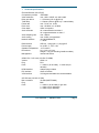
Technical Specifications
Encoder/Decoder (VX-HDV-IP)
Compression process
JPEG2000
Video resolution
max. 1920 x 1080P, min. 640 x 480I
Delay per device
≈ 1.5 frames (=25 ms @ 60 Hz)
Total delay
≈ 3 frames (=50 ms @ 60 Hz) + network delay
Frame rate
max. 72 Hz, min. 24 Hz
Pixel clock
max. 150 MHz, min. 25 MHz
Color depth
12Bit / component
Audio channels
16 in same direction as video **
16 in opposite direction to video **
Audio sampling rate
max. 192kHz
Audio coding
max. 32 Bit, uncompressed
Network interface
10/100/1000BaseTX,
1 x RJ45
Data interface
USB 2.0, 1 plug type A, 1 plug type B
Power supply
2x 12VDC +/- 10%, 13W
Operation temperature -10°C to 60°C
Dimensions
211 x 210 x 41.5mm,
Weight 1.3 kg (not including interface module)
Management
Internal web server
HDMI / DVI / VGA card (VX-HDV-IP-HDMI)
Version
HDMI 1.3
Plug
DVI-I
Ports
1 x video in (for encoder), 1 x video out (for
decoder)
HDMI interface
Adapter plug included
DVI interface
direct connection
VGA interface
VGA signal receivable but not transmittable
HD-SDI card (VX-HDV-IP-SDI)
Max. resolution
3G-SDI (SMPTE424M)
Plug
BNC
Ports
1 x video in (for encoder) or gen-lock
1 x video out (for loopback)
2 x video out (for decoder)
724-746-5500 | blackbox.com
Page 5
Audio card
Audio frequency range
Audio channels
Audio interfaces
Page 6
20Hz – 20kHz
Encoder: 2 x audio in, 2 x audio out
Decoder: 2 x audio in, 2 x audio out
Line-In and Out, Mic-In, Headph.-Out and
RS-232-Interface
724-746-5500 | blackbox.com
2
Overview
2.1 Summary description
The VX-HDV-IP modular JPEG 2000 IP encoder/decoder system for
HD video and audio is configurable as encoder or as decoder. Two different
video interface modules are currently available: DVI-I and 3G-SDI. HDMI and
VGA transmission is also possible by means of simple converters.
A separate audio interface is available to enable one bidirectional audio
channel for an Intercom connection.
2.2 Special features
Thanks to HD image quality, the system is ideally suited for professional
applications. The modular video interface also enables interface mixing
within the same installation, such as from an HD-SDI source to an HDMI
device.
The VX-HDV-IP is an independent encoder that delivers full HD 1080p/60Hz
video streams without any quality impairment via conventional 10/100/
1000 BASE-T networks. VX-HDV-IP encoders/decoders can be simply
interconnected via existing networks (LANs and WANs) as well as by
Internet.
The VX-HDV-IP functions equally well in point-to point or in point-tomultipoint connections.
724-746-5500 | blackbox.com
Page 7
2.3 How it works
The encoder receives and compresses the incoming HD video signal and
transmits it via LAN or WAN. The decoder decompresses and passes on the
original video signal to the device connected. With adequate LAN/WAN
bandwidth, the signal quality is not reduced. And thanks to the JPEG 2000
compression process, the image is not affected by artefacts or stutter.
System delay (latency), network delay not included, is less than three
frames. Multicast is supported, which means the image from one source can
be simultaneously displayed on several monitors. The connections between
encoders and decoders are defined by simple IP-addressing, enabling easy
re-switching of connections without the need of crossbars.
2.4 Plug-in connections
• Slot for video interfaces (DVI-I or 3G-SDI)
• Slot for audio input/output (not yet available)
• Redundant power input 12 VDC
• Alarm switch contact
• Two USB connections ([1] USB-A, [1] USB-B)
• Console port (USB plug)
2.5 Scope of delivery
• VX-HDV-IP basic housing
• (4) rubber feet for tabletop version
• Video board (DVI-I or 3G-SDI, as required)
• 12 VDC external power supply (optional)
• 19-inch rackmounting kit (optional)
Page 8
724-746-5500 | blackbox.com
3
Installation
The VX-HDV-IP is intended for indoor installation. The operating temperature
limits are -10° C to +60° C. Two or more devices stacked above each other
must be adequately spaced to ensure sufficient cooling.
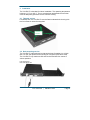
3.1 Tabletop version
For tabletop use, the VX-HDV-IP must be fitted underneath the housing with
the four screw-on rubber feet supplied.
Fit rubber
feet here
3.2 Rack-mounting version
The VX-HDV-IP is dimensioned so that two devices fit together in a 19-inch
rack. For this, the optional rack mounting kit is required (VX-HDV-IP-RM).
The VX-HDV-IP only needs one HU and can be fixed with four screws in
various positions:
Front connections,
flush with edge of rack
724-746-5500 | blackbox.com
Page 9
Front connections, set back
approx. 2 cm (for plug protection)
Rear connection,
flush with edge of rack
Rear connection,
set back approx. 2 cm
Page 10
724-746-5500 | blackbox.com
3.3 How to change and insert the video interface modules
These modules are fixed with two screws. To change a module, release both
screws and carefully remove the module.
When installing a module, make sure that the board is supported on the
guiderails at each side, and insert the module precisely in the straight or
horizontal position until the connector engages.
Æ Always shut the power off before changing modules!
Fixing screws
3.4 Power supply and switch contact
To activate the VX-HDV-IP, a 12-VDC/2-A power supply is required.
The two separate power input connections on the back allow for a redundant
power supply. If you only use one power supply, you can connect it to either
of these inputs.
The switch contact is used for monitoring the two power inputs. It closes to
signal a power failure, for example, to a control system.
724-746-5500 | blackbox.com
Page 11
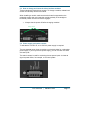
4
Description
The basic housing has a 10/100/1000TX Ethernet connection and two USB
ports (USB 1 and USB 2) for KVM applications.
The console port is exclusively for maintenance work and is not useraccessible.
The reset button on the left returns the device to factory default setting if
required. Press this button for at least five seconds until the green power
LED starts flashing to signal a reboot.
The DVI module has two connections: Video In and Video Out. The
VX-HDV-IP can be configured as an encoder or as a decoder. Only one
connection can be activated at a time.
Æ The quality of the video cable can influence the video image quality.
The LED of the configured port stays red if no connection is detected. This
indicates whether it is configured as an encoder or a decoder, because the
LED only goes green if the VX-HDV-IP detects a recognizable connection.
The port is then ready for use.
Front view of VX-HDV-IP with DVI module
Ethernet port
Reset
USB for KVM
Power
LED
Video in
LEDs DVI
Video out
Reserve slot for
audio module
The VX-HDV-IP has two 12 VDC power inputs; one is redundant. Both power
inputs are monitored by a switch contact that closes to signal a power failure,
for example, to a control system.
Rear view of VX-HDV-IP
Page 12
724-746-5500 | blackbox.com
Status LED
LED
Power
LED
Color
green
red
left
LAN
port
right
yellow
amber
green
green
DVI
port
red
Status
on
off
Flashes
every 3
seconds
Flashes
every second
Flashes
every 0.2
seconds
Flashes
every second
Description
Ready for use
No power
On
Flashing
Off
on
on
Network detected
Data transmission
No network
Connection speed 10/100 Mbps
Connection speed 1000 Mbps
On
Flashes
every 3
seconds
Off
On
Rapid
flashing
Ready for use, but not on line
Ready for use and on line, but no
video stream
Booting after hardware or software
reset
Identifying device (see 5.2: System
Configuration)
Device connected, streaming
(transmitter only in case of EDID
reception)
Device connected, video streaming
but no audio (receiver only)
Not connected
Connection active, but no device
present or ready
Identifying device (see 5.2: System
Configuration)
724-746-5500 | blackbox.com
Page 13
5
Web interface
5.1 VX-HDV-IP system start-up
The VX-HDV-IP is delivered with a preconfigured IP address. Before startup, the IP address must be reconfigured and the device defined either as
encoder or decoder (the two functions cannot be used in parallel).
• Connect the Ethernet port (RJ-45) of the VX-HDV-IP with shielded CAT5e
cable to a Ethernet switch or network.
• Connect the monitor to the Video Out port.
or
• Connect the video source to the Video In port.
Access via Web browser
Default settings:
IP address
192.168.001.200
Subnet mask 255.255.255.000
Gateway
192.168.001.001
Per default, the devices are configured so that no password is required.
Page 14
724-746-5500 | blackbox.com
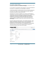
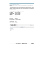
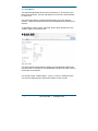
5.2 Ethernet
In the first register, you can define the IP address, the subnet mask, and the
gateway. You can also allocate an IP address from the network by activating
the DHCP checkbox. Before activation, make sure a DHCP server is present
in the network. Two DNS server addresses can also be defined.
For easier identification, you can also assign a name to the device and
designate a caption.
The default name is “device_0” and the device caption is “e.q. blu-ray
player.”
After entering the network data, define the system operating mode of the
device—either as receiver or transmitter—by checking the box next to
System mode in the screen.
To distinguish between several VX-HDV-IP devices in a rack, activate
“Identify device.”
All the LEDs in the device you want to identify will then flash red.
Press the “Apply” key to confirm and activate your changes. If everything
works correctly, press “Save” to finalize all changes.
This ensures that your new settings will still be active after a reboot.
Press “Undo” to cancel a command without saving.
724-746-5500 | blackbox.com
Page 15
5.3 Transmitter stream settings
You can either set up a point-to-point connection (unicast) or a multicast
connection to video stream receivers in the network that support the
multicast address.
For connections that need to pass through firewalls, the RTSP TCP port
can be separately defined. To avoid unnecessary network loading, the
video stream size can be defined by setting a maximum data rate, for
example, 80 Mbps (see below). For an optimal HD video stream, the data
rate setting should not be less than 30 Mbps. With “Auto stream” activated in
the stream configuration checkbox, the video stream starts as soon as a
connection between two units is made.
For additional security against eavesdropping, activate “Force HDCP” (High
Definition Content Protection) to protect video streams that are not from
HDCP encrypted sources. HDCP encrypted sources will always be
transmitted with HDCP encryption. This feature must be selected only at one
device to be activated.
Chroma Data Rate
This menu item uses the available bandwidth optimally for color
(chromaticity), then brightness (luminance). If the brightness is more
important than the color, the proportion of Chroma can be reduced.
When Chroma is set to 100%, 50% of the bandwidth is used for Chroma and
50% is used for Luma (brightness of the image points). In the extreme case
(black/white picture), only half of the set bandwidth is used because Chroma
generates almost no data.
Page 16
724-746-5500 | blackbox.com
When Chroma is set to 50%, 25% of the bandwidth is used for Chroma and
75% of the bandwidth is used for Luma.
When Chroma is set to 0%, 100% of the bandwidth is used for Luma.
IP TTL (time to life)
This is a mechanism that limits the lifetime of data in a network. Once the
prescribed timespan has elapsed, data is discarded.
The range is between 0–255 seconds.
Reduce the refresh rate
In connection with the software decoder of EIT, the refresh rate can be
reduced, so that only every second or every third or even only every 4th
image is transferred. Thus, the data volume gets smaller and the computer
that is running the software uses less CPU power.
Traffic shaping
Traffic shaping is a form of rate limiting. Use it to optimize or guarantee
performance, improve latency, and/or increase usable bandwidth.
Possible range for Max datarate is: 1–800 MBps
If the max data rate is set as 30 Mbit/s and you change it to 70 Mbit/s, for
example, with a resolution of 1080i, the stream will stop and rebuild a new
stream. This is because if we have a stream <50 Mbit/s we need only two
compression chips. If the stream is bigger than 50 Mbit/s, we need four
compression chips. The transmitter has to inform the receiver (when
rebooting) that now it has to use four compression chips.
Æ The maximum data rate for interlaced resolutions, such as 1080i,
must not exceed 140 MBps.
724-746-5500 | blackbox.com
Page 17
5.4 Transmitter status reports
The example below shows a VX-HDV-IP with activated media player (no
HDCP encryption).
Operation mode:
Video sink:
Video source:
Resolution:
The device is configured as video transmitter box
(vtb)
No monitor is connected
connected to activated media player
Video stream resolution, frame rate, and pixel
frequency
Stream 0 (Video out): Playing = video stream currently sending
Stream 1 (Audio out): Playing = audio stream currently sending
Checking the video source
If the unit is configured as transmitter and one source is connected to the
video-in port, all video-out ports are loopback active and you can see the
stream.
Page 18
724-746-5500 | blackbox.com
5.5 Choose the receiver’s EDID
By default, the transmitter requires the EDID of the sink (e.g. monitor), so
that the best possible resolution the receiver can handle is delivered. When
an EDID is received, the transmitter sends a video stream. If the sink cannot
send an EDID, the transmitter has to be set to “Use default EDID.” The video
stream is then sent with the same resolution as the video source.
On Multicast modus, the EDID is set automatically as “use default EDID.”
Be sure that all monitors support the settings from the source.
724-746-5500 | blackbox.com
Page 19
5.6 Receiver stream settings
The receiver must also know where the video stream is coming from, so the
transmitter IP address must be entered accordingly.
If “Force HDCP” was activated on the transmitter, it must not be activated on
the receiver. It is sufficient if it is only activated on one device.
As with the transmitter, the different ports can also be manually adjusted on
the receiver. Here again, the port details settings must be the same for
transmitter and receiver to enable transmission.
Depending on the network constellation, the maximum network delay for
transmission must be set accordingly. With large networks, it is better to set
a longer delay so that the video stream is temporarily stored before
transmission. This ensures a constant video stream even in the case of
complex networks. Changing the maximum network delay reboots the
connection and interrupts the video stream because the buffer has to be
read in again.
Since the video and the audio stream is not processed identically—video
stream is compressed, audio stream is not— there may be delays in the
transmission of sound and image. To achieve a lip-synchronous
transmission, the “audio-video delay” can be adapted with values between
100 ms and 100 ms. Here, too, the change of this size reboots the
connection because the buffer has to be read again.
Page 20
724-746-5500 | blackbox.com
The OSD (On Screen Display) setting defines how long information is shown
on the monitor. The setting range is 0–100 seconds. At 0 setting, nothing will
be displayed, and at 100 setting the display remains on screen.
Typical On Screen Display (OSD)
724-746-5500 | blackbox.com
Page 21
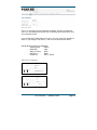
5.7 Receiver status reports
The example below shows a VX-HDV-IP with an activated monitor.
Operation mode:
Video sink:
Video source:
Resolution:
The device is configured as video receiver box (vrb).
A monitor is connected and activated.
No video source is connected.
Only displays on the transmitter box
Stream 0 (Video out): playing = video stream currently sending
Stream 1 (Audio out): playing = audio stream currently sending
The three keys at the top right corner are for starting, stopping, or
reconnecting the video stream.
Page 22
724-746-5500 | blackbox.com
5.8 Receiver video interface test
You can test the video output interface’s quality and function on the DVI
board at three possible resolutions: 1080p60, 1080p24, and 720p60.
724-746-5500 | blackbox.com
Page 23
5.9 Firmware upgrade
1. Save the new firmware as example “image_v4_02.img” file in a folder on the
computer from where the update is executed.
2. Connect to the VX-HDV-IP via a Web interface.
3. Select “Firmware” in the Web interface menu.
4. Activate the icon “select a file” and press “Apply.” A new folder will open.
5.
6.
7.
8.
Select “Search” to get the “image_v4_02.img” file.
Click “Upload.”
An upload progress bar is now displayed.
After about four minutes, the firmware is upgraded and ready to reboot.
Page 24
724-746-5500 | blackbox.com
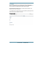
5.10 Factory default restore
Here, you can reset the VX-HDV-IP encoder/decoder to factory defaults if
required.
The network details, names, and designations are restored to factory default
settings. Pressing the reset button on the front of the device for >5 seconds
has the same effect.
The factory default settings are as follows:
IP address
Subnet mask
Gateway
192.168.001.200
255.255.255.000
192.168.001.001
Username
Password
admin
admin
Host name:
device_0
Device caption: e.q. blu-ray player
System mode: none
Max. data rate: 80 MBps
724-746-5500 | blackbox.com
Page 25
5.11 Settings
Here you can choose German or English as the system language, and
define or change the user name and password for access authentication. To
use the VX-HDV-IP with AMX devices, AMX must be activated.
With authentication activated, you can no longer access the device if you
forgot your user name or password.
To re-enable access, reset the device to factory default by pressing the reset
button on the front for at least five seconds.
Page 26
724-746-5500 | blackbox.com
6
USB ports
Each VX-HDV-IP device has two USB-A ports, and a USB-B port for future
use with KVM. The current USB port supports only the features for keyboard
and mouse.
Each VX-HDV-IP unit can be configured as a host or as a device. Just
activate the function you want. The USB cable length is maximum 3 m.
If you configure the unit as a host, the USB-2 interface will be active and you
can connect a keyboard or a mouse to it.
If you configure the unit as a device, the USB-1 interface will be active and
you can connect it to your PC.
724-746-5500 | blackbox.com
Page 27
7
FEC Forward Error Correction according to SMPTE 2022-1
In telecommunication, information theory, and coding theory, forward error
correction (FEC) or channel coding is a technique used for controlling errors
in data transmission over unreliable or noisy communication channels. The
central idea is the sender encodes their message in a redundant way by
using an error-correcting code (ECC).
The redundancy allows the receiver to detect a limited number of errors that
may occur anywhere in the message, and often to correct these errors
without retransmission. FEC gives the receiver the ability to correct errors
without needing a reverse channel to request retransmission of data, but at
the cost of a fixed, higher forward channel bandwidth.
The FEC doesn’t support the audio from the external audio interface.
FEC Enable: for video and audio separately selectable
Size of matrix: settings between 4 and 10
To calculate the redundant packets, all packets to be transmitted are placed
in a matrix. The size of the array determines how many packets can be
recovered. The smaller the matrix, the more bandwidth is provided to the
redundant packets (= more overhead) and more packets can be recovered.
But the larger the matrix, more packets must be buffered before sending, so
the latency is greater. The lower the bandwidth, the greater is this effect.
e.g.: low bandwidth (1 frame = 17 Ethernet packets) and a size of 10 x 10, 6
images need to be cached before the redundant packets may be calculated.
Thus, at 60 Hz refresh rate, the network delay at the receiver to 1/60 Hz * 6 =
100 ms must be increased to ensure the restoration works. With a high
bandwidth (1 picture = 250 Ethernet packets), the additional delay is only
1/60 Hz * 100/250 = 7 ms. In the example with set low bandwidth (1 frame =
17 Ethernet packets), the die size is set to 4 x 4, so only one image needs to
be cached, thus the additional delay is only 17 ms.
Page 28
724-746-5500 | blackbox.com
Column only: If enabled, SMPTE 2022-1 Level A; disabled, Level B. Level A
sends only one FEC stream, so only single packets are recovered. The
overhead is smaller than for Level B. For Level B, in addition, several
consecutive packets can be restored (it is at most as many as for “Size of
matrix” set). Overhead in %: Depends on the matrix size, see table.
Overhead: The spectrum additionally required when FEC is turned on. If the
bandwidth is set to 100 Mbit (= 40% overhead), and a 5x5 matrix increases
the total bandwidth to 140 Mbit, the overhead is calculated as follows:
Column only switched on:
Overhead = 1 / "size of matrix"
= For example size of matrix = 5, overhead = 1/5 = 0.2
Column only off:
Overhead = ("size of matrix" + "size of matrix") / ("size of matrix" * "size of
matrix")
= For example size of matrix = 5, overhead = (5 +5) / (5 * 5) = 0.4
724-746-5500 | blackbox.com
Page 29
Receiver settings
Restrictions: An additional audio board is not supported by FEC, but how
many packets are not recovered is visible.
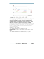
Measured Bandwith according to different Matrix settings
FEC-Matrix
Overhead
5
8
40%
25%
Latency by
30 Mbps
24 ms
35 ms
Latency by
50 Mbps
20 ms
30 ms
Latency by
80 Mbps
18 ms
27 ms
Firewall: you have to set the video-port n and also the ports n+2 and n+4
Page 30
724-746-5500 | blackbox.com
8
Hardware reset instructions
On the front of the VX-HDV-IP is a slightly recessed reset button. To reboot
the device, press this button for less than five seconds. Pressing it for
longer than five seconds resets everything (IP address, user name, and
password) to factory default.
9
Console ports
The console port is exclusively for use by Black Box Technical Support.
724-746-5500 | blackbox.com
Page 31
10 Audio-Board
The optional audio board has two line-in interfaces, Lin-In and Mic-In and
two line out-interfaces, Line-out and Head-out. It also has a serial interface
for future use.
In this firmware version, the audio interface works only as an intercom
solution. It builds a bidirectional audio-channel between a transmitter and a
receiver.
To activate the audio function, select the “audio” (audio board) icon in the
“stream” folder on the receiver unit.
This audio stream will be streamed parallel to the video/audio-stream from
the main board. The stream is not compressed and HDCP and FEC have no
functionality in this stream.
In the folder “audio,” select whether “Line-In” or “Mic-In” should be active.
You can also adjust the gain and boost the Micro-In with +20 dB.
Page 32
724-746-5500 | blackbox.com
The Lin-In and both Line-out interfaces are stereo. The Mic-In interface is
mono. It is not possible to use both line in interfaces at the same time. Only
one is active at a time.
If you configure the audio board as “Line-In” only, the “Line-Out” interface is
active. If you configure it as “Mic-In,” both line-out interfaces are active.
Specifications according to datasheet:
- Sampling rate
48kHz
- Resolution
16bit
- SNR Lin-In/Out
90db
- SNR Mic-In
80dB
- Frequency
20Hz – 20kHz
Jack 3,5mm, pin assignment
724-746-5500 | blackbox.com
Page 33
11 Supported resolutions
HDMI / DVI:
All resolutions up to 150 MHz pixel clock (1920 x 1080)
VGA:
640 x 480 @ 60 Hz/72 Hz/75 Hz/85 Hz
800 x 600 @ 56 Hz/60 Hz/72 Hz/75 Hz/85 Hz
1024 x 768 @ 60 Hz/70 Hz/75Hz/85 Hz
1280 x 1024 @ 60 Hz/75 Hz
SDI:
1080p60/30
1080p50/25
1080p24
720p60
720p50
720p30
720p25
720p24
1080i60
1080i50
1080s24
480i60
480i50
576i50
Page 34
724-746-5500 | blackbox.com
VX-HDV-IP, rev. 1
724-746-5500 | blackbox.com