1
quick start guide
hp surestore fc
1Gb/2Gb switch 16B
www.hp.com
Notice
Safety notices
© Hewlett-Packard Company, 2001. All rights reserved.
Any servicing, adjustment, maintenance, or repair must be
performed only by authorized service-trained personnel.
Part number: A7340-96002
Edition: E1201
Format conventions
Hewlett-Packard Company makes no warranty of any
kind with regard to this material, including, but not
limited to, the implied warranties of merchantability and
fitness for a particular purpose. Hewlett-Packard shall not
be liable for errors contained herein or for incidental or
consequential damages in connection with the furnishing,
performance, or use of this material.
This document contains proprietary information, which is
protected by copyright. No part of this document may be
photocopied, reproduced, or translated into another
language without the prior written consent of
Hewlett-Packard. The information contained in this
document is subject to change without notice.
variable
Indicates that you must supply a value.
output
Denotes text displayed on the screen.
[]
Indicates that the enclosed element is
optional and may be left out.
{}
Indicates that you must specify one of the
listed options.
|
Separates alternatives.
...
Indicates a repetition of the preceding
parameter.
Tip
Denotes ideas for enhanced product usage.
Use, duplication, or disclosure by government is subject
to restrictions as set forth in subdivision (c) (1) (ii) of the
Rights in Technical Data and Computer Software Clause
at DFARS 252.227.7013.
Note Denotes significant concepts or operating
instructions.
Warranty
CAUTION Denotes a hazard that can cause hardware or
software damage.
If you have any questions about the warranty for this
product, contact your dealer or local Hewlett-Packard
sales representative.
Trademarks
BROCADE, the Brocade B weave logo, Brocade: the
Intelligent Platform for Networking Storage, SilkWorm,
and SilkWorm Express, are trademarks or registered
trademarks of Brocade Communications Systems, Inc. or
its subsidiaries in the United States and/or in other
countries.
All other brands, product or service names are or may be
trademarks or service marks of, and are used to identify
products of services of their respective owners.
WARNING Denotes a hazard that can cause personal
injury or death.
CONTENTS
Revision History . . . . . . . . . . . . . . . . . . . . . . . . . . . . . . . . . . . . . . . . . . . . v
Updates . . . . . . . . . . . . . . . . . . . . . . . . . . . . . . . . . . . . . . . . . . . . . . . . . . . v
Related Publications . . . . . . . . . . . . . . . . . . . . . . . . . . . . . . . . . . . . . . . . . v
1
Installing the Switch . . . . . . . . . . . . . . . . . . . . . . . . . . . . . . 1
Product Description . . . . . . . . . . . . . . . . . . . . . . . . . . . . . . . . . . . . . . . . .
Safety Guidelines . . . . . . . . . . . . . . . . . . . . . . . . . . . . . . . . . . . . . . . . . . .
Package Contents . . . . . . . . . . . . . . . . . . . . . . . . . . . . . . . . . . . . . . . . . . .
Installing the Switch as a Stand-Alone Unit . . . . . . . . . . . . . . . . . . . . . . .
Installing the Switch in a Rack . . . . . . . . . . . . . . . . . . . . . . . . . . . . . . . . .
2
1
1
2
3
4
Setup . . . . . . . . . . . . . . . . . . . . . . . . . . . . . . . . . . . . . . . . . 13
System Components . . . . . . . . . . . . . . . . . . . . . . . . . . . . . . . . . . . . . . . .
SFP Media Side . . . . . . . . . . . . . . . . . . . . . . . . . . . . . . . . . . . . . . . . .
Power Supply Side . . . . . . . . . . . . . . . . . . . . . . . . . . . . . . . . . . . . . . .
Power Supply . . . . . . . . . . . . . . . . . . . . . . . . . . . . . . . . . . . . . . . . . . .
Fabric Operating System . . . . . . . . . . . . . . . . . . . . . . . . . . . . . . . . . .
SFPs . . . . . . . . . . . . . . . . . . . . . . . . . . . . . . . . . . . . . . . . . . . . . . . . . .
Fibre Channel Cable Connections . . . . . . . . . . . . . . . . . . . . . . . . . . .
Configuring and Connecting the Switch . . . . . . . . . . . . . . . . . . . . . . . . .
Saving the System Configuration Files . . . . . . . . . . . . . . . . . . . . . . . . . .
Backing up the Switch Configuration Settings . . . . . . . . . . . . . . . . .
Restoring the System Configuration Settings . . . . . . . . . . . . . . . . . .
13
14
15
15
16
16
16
17
22
22
23
iii
Next Steps . . . . . . . . . . . . . . . . . . . . . . . . . . . . . . . . . . . . . . . . . . . . . . . .
Setting QuickLoop Mode on Ports . . . . . . . . . . . . . . . . . . . . . . . . . .
Setting Up Speed Negotiation . . . . . . . . . . . . . . . . . . . . . . . . . . . . . .
Configuring Supported Devices . . . . . . . . . . . . . . . . . . . . . . . . . . . .
3
Diagnostics . . . . . . . . . . . . . . . . . . . . . . . . . . . . . . . . . . . . 27
Switch Status Indicators . . . . . . . . . . . . . . . . . . . . . . . . . . . . . . . . . . . . .
LEDs on the SFP Media Side . . . . . . . . . . . . . . . . . . . . . . . . . . . . . .
LEDs on the Power Supply Side . . . . . . . . . . . . . . . . . . . . . . . . . . . .
Maintenance and Diagnostic Tests . . . . . . . . . . . . . . . . . . . . . . . . . . . . .
Error Messages . . . . . . . . . . . . . . . . . . . . . . . . . . . . . . . . . . . . . . . . . . . .
Getting Support . . . . . . . . . . . . . . . . . . . . . . . . . . . . . . . . . . . . . . . . . . . .
Service and Support . . . . . . . . . . . . . . . . . . . . . . . . . . . . . . . . . . . . . .
Additional Licenses . . . . . . . . . . . . . . . . . . . . . . . . . . . . . . . . . . . . . .
4
24
24
24
25
27
28
30
32
34
34
34
34
Specifications . . . . . . . . . . . . . . . . . . . . . . . . . . . . . . . . . . 35
General . . . . . . . . . . . . . . . . . . . . . . . . . . . . . . . . . . . . . . . . . . . . . . . . . .
Environmental . . . . . . . . . . . . . . . . . . . . . . . . . . . . . . . . . . . . . . . . . . . . .
Dimensions . . . . . . . . . . . . . . . . . . . . . . . . . . . . . . . . . . . . . . . . . . . . . . .
Power Supply . . . . . . . . . . . . . . . . . . . . . . . . . . . . . . . . . . . . . . . . . . . . .
35
36
37
37
Product Regulatory Information . . . . . . . . . . . . . . . . . . . 39
iv
Quick Start Guide
Revision History
December 2001
First release.
Updates
For the most current information about the HP Surestore FC 1Gb/2Gb
Switch 16B, visit the support Web site located at
http://www.hp.com/support/fc16B.
For information about product availability, configuration, and connectivity,
consult your HP account representative.
Related Publications
Related product information can be found in the following publications.
Those publications with part numbers are provided as printed copies with
your product. The HP Surestore FC 1Gb/2Gb Switch 16B Documentation
CD contains all publications listed in the table below and is also provided
with your product.
Title
Part Number
HP Surestore FC 1Gb/2Gb Switch 16B Quick
Start Guide
A7340-96002
HP Surestore FC 1Gb/2Gb Switch 16B
Documentation CD
A7340-11001
HP Surestore FC 1Gb/2Gb Switch 16B
Installation and Reference Guide
Available only on CD
Fabric OS Reference Manual, version 3.0
Available only on CD
Fabric OS Procedures Guide, version 3.0
Available only on CD
Fabric OS Version 3.0 Release Notes, version 3.0 Available only on CD
Fabric Watch User’s Guide, version 3.0
Available only on CD
QuickLoop User’s Guide, version 3.0
Available only on CD
Web Tools User’s Guide, version 3.0
Available only on CD
v
Title
Part Number
Distributed Fabrics User’s Guide, version 3.0
Available only on CD
Zoning User’s Guide, version 3.0
Available only on CD
MIB Reference Manual, version 3.0
Available only on CD
ISL Trunking User’s Guide, version 3.0
Available only on CD
Advanced Performance Monitoring User’s Guide, Available only on CD
version 3.0
Merging Heterogeneous Fabrics Instructions
Available only on CD
For information about Fibre Channel standards, visit the Fibre Channel
Association Web site, located at http://www.fibrechannel.com.
vi
Quick Start Guide
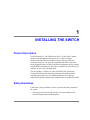
1
INSTALLING THE SWITCH
Product Description
The HP Surestore FC 1Gb/2Gb Switch 16B is a 16-port Fibre Channel
gigabit switch that supports link speeds up to 2 Gbps. Each port
automatically negotiates to the highest common speed of all devices
connected to the port. The ports are compatible with SFPs (small form
factor pluggable media), are universal and self-configuring, and are capable
of individually becoming an F_Port (fabric enabled), FL_Port (fabric loop
enabled), or an E_Port (expansion port).
The base product, A7340A/AZ, comes with Web Tools, QuickLoop,
Zoning, and Fabric Watch. Switches purchased with the Performance
Upgrade (Option 001) have four additional features: ISL Trunking,
Advanced Performance Monitoring, Extended Fabrics, and Remote Switch.
Safety Guidelines
Follow these safety guidelines to ensure successful and safe operation of
the switch:
• The supply circuit, line fusing, and wire size must conform to the
electrical rating on the switch nameplate.
1
• The ambient air temperature near the switch must not exceed 40 degrees
Celsius. This is particularly important to verify if the switch is installed
in a closed or multi-rack assembly.
• The volume of air flow available to the switch must be at least 300 cubic
feet per minute. The air vents must not be blocked.
Follow these safety guidelines for rack-mount installation:
• The rack space must be 1U high, 19 inches wide, and 24 inches deep.
• All equipment installed in the rack should have a reliable branch circuit
ground connection. Do not rely on a connection to a branch circuit, such
as a power strip.
• The additional weight of the switch should not unbalance the rack or
exceed the rack’s weight limits.
• The rack should be mechanically secured to insure stability in the event
of an earthquake.
WARNING For safety reasons, when installing this product in an
equipment rack, you must consider rack stability against tipping. Please
refer to the Hewlett-Packard Rack System/E User's Manual provided with
the equipment rack to determine rack stability (also available in electronic
format through the HP Web site at http://www.hp.com/racksolutions/). If the
necessary stability is not achieved, through the placement of additional
equipment or ballast, the equipment rack must be anchored to the building
structure before operation.
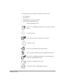
Package Contents
The major items contained in the FC 16B shipping carton(s) include the
following items:
• One FC 16B switch, two fan trays, and one or two power supplies
installed
• One 10 ft. RS-232 serial cable (convertible to an RJ-45 connector
through removal of the adapter on the end of the cable)
• Two 6 ft. power cables (according to the number of power supplies
included with the switch)
2
Quick Start Guide
• Four rubber mounting feet (used only for setting up the switch as a
stand-alone unit)
• Two rails and one bag of rail mounting hardware (required if the switch
is to be installed in a rack):
• hp surestore FC 1Gb/2Gb Switch 16B Quick Start Guide
• HP Surestore FC 1Gb/2Gb Switch 16B Documentation CD-ROM
Installing the Switch as a Stand-Alone Unit
This section provides instructions for setting up the switch as a stand-alone
unit on a flat surface. The following items are required:
• FC 16B switch
• Power cables
• Rubber mounting feet
To set up the switch as a stand-alone unit:
1. Check contents of the shipping carton to verify all the required parts and
hardware are available.
2. Apply the rubber feet by completing the following steps:
Installing the rubber feet on the switch is recommended to help
prevent the switch from accidentally sliding off the supporting surface.
CAUTION
a. Clean the four depressions that are at each corner of the bottom of the
switch to ensure they are free of dust.
b. Place a rubber foot in each depression, with the adhesive side against
the chassis, and press into place.
3. Place the switch on a flat, sturdy surface.
4. Provide power to the switch by completing the following steps:
a. Connect the power cable to the FC 16B power supply and to a power
outlet. Ensure the power cable is routed so that it is not exposed to
stress.
Installing the Switch
3
b. Turn on the power supply (flip the AC switch to “I”) when ready to
supply power to the switch. The switch automatically runs POST
(power on self-test) each time it is turned on.
c. If the FC 16B includes a second power supply, repeat Steps 4a and 4b
for the remaining power supply.
Note Do not connect the switch to the network until the IP address is
correctly set. For instructions on how to set the IP address, see
“Configuring and Connecting the Switch” on page 17.
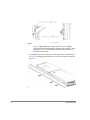
Installing the Switch in a Rack
This section provides instructions for installing the FC 16B in an HP or
Compaq/Rittal rack.
Figure 1. FC 16B Rack-Mounted Switch
4
Quick Start Guide
The following items are required to install the switch in a rack:
• FC 16B switch
• Power cables
• #2 Phillips and T25 Torx screwdrivers
• Rails and rail mounting hardware:
(2) Rear mounting bracket
(6) #8-32 x 5/16 Phillips pan-head screw with captive star lock
washer
(6) #8 Flat washer
(6) M5 Torx head screw with captive lock washer
(2) Rubber washer
(4) M5 U-type Tinnerman clip (HP rack only)
(4) #10-32 square Tinnerman nut (Compaq/Rittal rack only)
(4) #10-32 x 5/8 Phillips pan-head screw with attached lock
washer (Compaq/Rittal rack only)
(6) Spacer (Compaq/Rittal rack only)
(4) M5 flat washer (Compaq/Rittal rack only)
Installing the Switch
5
For proper airflow, the SFP media side of the FC 16B faces the
rear of the rack. This mounting allows air to enter from the front of the rack
and to exhaust at the rear of the rack, similar to other rack-mounted
equipment. This prevents switch overheating which may cause it to fail
CAUTION
To install the switch in a rack:
1. Check contents of the shipping carton to verify all the required parts and
hardware are available.
2. Choose a mounting location in the rack for the switch.
3. Attach the rear rail-tray brackets to the rear rack uprights by completing
one of the following steps:
– For an HP rack, install each of the two mounting brackets with (1)
M5 Torx head screw with captive lock washers as shown in Figure 2.
Figure 2. Installing the Rear Rail-Tray Brackets (HP Rack-left rear upright))
6
Quick Start Guide
– For a Compaq/Rittal rack, assemble each of the two brackets with (2)
spacers, (2) M5 flat washers, and (1) M5 Torx head screw with
captive lock washers as shown in Figure 3.
For the Compaq/Rittal rack, the alignment pins will be resting on
the top surfaces of the spacers.
Note
Figure 3. Installing the Rear Rail-Tray Brackets (Compaq/Rittal Rack)
4. Install the Tinnerman clips or nuts by completing one of the following
steps:
– For an HP rack, install (2) M5 U-type Tinnerman clips for each of
the front columns of the rack in the top and bottom positions of the
three-hole EIA pattern as shown in Figure 4.
Installing the Switch
7
Figure 4. Installing the Tinnerman Clips (HP Rack)
– For a Compaq/Rittal rack, install (2) #10-32 square Tinnerman nuts
for each of the front columns of the rack in the top and bottom
positions of the three-hole EIA pattern. Also install (1) spacer in the
center position for each column on the front of the rack. See
Figure 5.
Figure 5. Installing the Tinnerman Nuts and Spacers (Compaq/Rittal Rack)
8
Quick Start Guide
5. Assemble the outer rails by completing the following steps:
a. As an aid in assembly, two rubber washers have been included to help
keep the rear slotted portion of the outer rail flush against the rear
rail-tray brackets. Install them as shown in Figure 6.
Figure 6. Installing the Rubber Washers
b. Insert the alignment pins attached to the outer rail front flange into the
center opening in the rack.
For the Compaq/Rittal rack, the alignment pins will be resting on
the top surfaces of the spacers.
Note
c. Depending on the rack you are using, complete one of the following
tasks:
– For an HP rack, install one M5 Torx screw in the upper hole
location of the right rail. Then, install one M5 Torx screw in the
lower location of the left rail. See Figure 7.
Note
Installing the Switch
Do not install the upper left and lower right screws until later.
9
Figure 7. Assembling the Outer Rails (HP Rack)
– For a Compaq/Rittal rack, install one #10-32 x 5/8 Phillips
pan-head screw in the upper hole location of the right rail. Then,
install one #10-32 x 5/8 Phillips pan-head screw in the lower
location of the left rail.
6. Assemble the two inner rails (one on each side) to the switch using (6)
#8-32 x 5/16 Phillips pan-head screws, and #8 flat washer as shown in
Figure 8.
Figure 8. Assembling the Inner Rails
10
Quick Start Guide
Do not use any other screws other than the six that are provided.
Use of any longer lengths can cause damage to internal components of the
switch. Before tightening screws, make sure that the rails are centered to
the overall height of the switch.
CAUTION
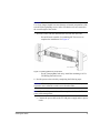
7. Insert the switch with the attached inner rails into the outer rails.
– For an HP rack, assemble (2) remaining M5 Torx screws to
complete the installation. See Figure 9.
Figure 9. Installing Switch into an HP Rack
– For the Compaq/Rittal rack only, install the remaining #10-32 x
5/8 Phillips pan-head screws.
8. Provide power to the switch by completing the following steps:
Ensure the power cable or cables are routed so that they are not
exposed to stress when the switch is moved on the slides.
CAUTION
Allow for 1U space in the rack for every 10 switches to facilitate
power cable management.
Note
a. Connect the power cable to the FC 16B power supply and to a power
outlet.
Installing the Switch
11
b. Turn on the power supply (flip the AC switch to “I”) when ready to
supply power to the switch. The switch automatically runs POST
(power on self-test) each time it is turned on.
c. If the FC 16B includes a second power supply, repeat Steps 8a and 8b
for the remaining power supply.
Note Do not connect the switch to the network until the IP address is
correctly set. For instructions on how to set the IP address, see
“Configuring and Connecting the Switch” on page 17.
12
Quick Start Guide
2
SETUP
System Components
The HP Surestore FC 1Gb/2Gb Switch 16B consists of the following
components:
• A 1U chassis, designed to be mounted in a 19-inch rack, with forced-air
cooling that flows from the power supply side of the switch to the SFP
media side.
• 16 optical ports, compatible with SFPs (small form factor pluggable
media).
• One RS-232 serial port (DB9 connector) on the SFP media side.
• One IEEE compliant RJ-45 connector on the SFP media side for use
with 10/100 Mbps Ethernet or in-band.
• A total of 36 LEDs:
– Two LEDs for each of the 16 ports to indicate port status and link
speed information.
– One LED on each power supply to indicate the status of that power
supply.
– One LED on the left of the SFP media side to indicate whether the
switch has power.
13
– One LED in the center of the power supply side to indicate the
overall switch status.
• Two universal input and redundant power supplies with AC switches
and built-in fans. The power supplies plug into internal blind-mate
connectors when installed in the chassis.
• Two fan trays, each containing two fans. Air is pulled in through the rear
intake and pushed out through the vents on the SFP media side. The fans
provide adequate cooling for the maximum switch power rating of 102
Watts.
• Three digital thermometers, capable of sensing a temperature range
from -55 °C to +125°C, in 0.5°C increments.
• A motherboard that is completely enclosed in an EMI (electromagnetic
interference) enclosure tray. The logic and chassis ground are connected
to the chassis by screws. The embedded processor can process frames
up to 1024 bytes.
• A real-time clock (RTC) with a 10-year, non customer-replaceable
battery and 56 bytes of NVRAM.
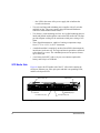
SFP Media Side
Figure 10 shows the SFP media side of the FC 16B, which contains the
serial port, Ethernet port, fiber optic ports and their corresponding LEDs,
and the switch power LED.
Switch Power LED
Ethernet Port
Serial Port
Port Status LED (16x)
Optical Port (16x)
Port Speed LED (16x)
Figure 10. The SFP Media Side of the FC 16B
14
Quick Start Guide
The ports on the SFP media side of the FC 16B are color-coded in groups
with four purple ports alternating with four unmarked ports to indicate
which ports can be used in the same ISL Trunking group.
Note ISL Trunking (an optionally licensed feature) is a Fabric OS feature
that enables distribution of traffic over the combined bandwidth of up to
four ISLs between two directly adjacent switches, while preserving
in-order delivery. For information about ISL Trunking, refer to the ISL
Trunking User’s Guide.
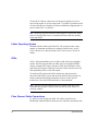
Power Supply Side
Figure 11 shows the power supply side of the FC 16B, which provides
access to the fan trays and power supplies and the Switch Status LED. Each
power supply also has an LED that indicates the status of that power
supply. The power supplies, fan trays, and entire switch are all FRUs (field
replaceable units).
Power Supply LED (2x)
Switch Status LED
AC Power Switch (2x)
Power Supply #2
Power Supply #1
Fan Tray Assembly (containing
fans #1 and 2)
Spring Latch (2x)
Fan Tray Assembly
(containing fans #3 and 4)
Figure 11. The Power Supply Side of the FC 16B
Power Supply
The power supplies are universal and capable of functioning worldwide
without using voltage jumpers or switches. They meet IEC 61000-4-5 surge
voltage requirements and are autoranging in terms of accommodating input
voltages and line frequencies. Each power supply has its own built-in fan
for cooling, pushing the air towards the SFP media side of the switch. See
“Power Supply” on page 37 for a list of power supply specifications.
Setup
15
To turn the FC 16B on, connect one or both power supplies to a power
source, then flip the AC power switch to the “I” position. To turn the switch
off, turn off both power supplies (if both are installed) by flipping each AC
power switch to the “O” position.
Note Removing all power from the switch triggers a system reset. When
power is restored, all devices are returned to the last saved state and the
switch runs POST.
Fabric Operating System
Included with the switch is the Fabric OS. The system provides a large
number of commands and libraries to manage real-time tasks. See the
Fabric OS Reference Manual and the Fabric OS Procedures Guide for
details.
SFPs
The FC 16B accommodates up to 16 SFPs (small form factor pluggable
media). The SFPs supported are the SWL (short wavelength) and LWL
(long wavelength) fibre-optics. Shortwave SFPs have black dots visible
from the front. Longwave SFPs have blue dots visible from the front. The
SFPs qualified by HP are 1Gb/2Gb capable.
To install an SFP, position the SFP so that the key (the tab near the
cable-end of the SFP) is on top and insert the SFP into the port until it is
firmly seated and the latching mechanism clicks. For more specific
instructions, refer to the SFP manufacturer’s documentation.
Note The SFP is keyed so that it can only be inserted with the correct
orientation into the port. If the SFP does not slide in easily, ensure it is
correctly oriented.
Fibre Channel Cable Connections
LC cables are used to plug into SFPs. The cables required for the
HP/Brocade 2400 and 2800 switches have SC connectors and connect into
16
Quick Start Guide
GBIC optic modules. LC to SC cables or adapters are required to connect
the cables together.
To connect an SC cable to the FC 16B, use the HP C7540A - 2M LC male SC male cable adapter.
Connect inter switch links (ISLs) between two FC 16B switches using an
LC to LC cable.
Table 1. Cables Used with the FC 16B
LC - SC Cable Connectors
Product
Number
Part
Number
C7534A
5183-2684
C7540A
N/A
C7529A
5065-5106
2m FC Cable LC-SC duplex M/M
C7530A
5065-5107
16m FC Cable LC-SC duplex M/M
Description
SC female - SC female adapter
2M LC male - SC male adapter kit contains both C7534A (adapter) and
C7529A (2 meter cable)
LC - LC Cables
Product
Number
Part
Number
C7524A
5065-5101
2m FC Cable LC duplex M/M
C7525A
5065-5102
16m FC Cable LC duplex M/M
C7526A
5065-5103
50m FC Cable LC duplex M/M
C7527A
5065-5104
200m FC Cable LC duplex M/M
Description
Configuring and Connecting the Switch
The following items are required to configure and connect the FC 16B for
use in a network and fabric:
• The FC 16B installed and connected to a power source
Setup
17
• Workstation that has a terminal emulator application (such as
HyperTerminal)
• Serial cable provided with the switch, for connecting the switch to the
workstation
• An unused IP address
• Ethernet cable for connecting the switch to the workstation or to a
network containing the workstation
• SFPs and FC cables, as required to connect the switch to the fabric
To configure the FC 16B and connect it to a fabric:
1. Replace the factory IP address and related information with the IP
information provided by your network administrator by completing the
following steps:
a. Remove the shipping plug from the serial port and insert the serial
cable provided with the FC 16B.
b. Connect the other end of the serial cable to an RS-232 serial port on
the workstation. If no RS-232 serial port is available on the
workstation, the adapter on the end of the serial cable can be removed
to use the RJ-45 connector to create a serial connection.
c. Verify that the switch power is on and POST is completed.
d. Disable any serial communication programs running on the
workstation.
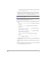
e. Open a terminal emulator application (such as HyperTerminal on a
PC, or TERM in a UNIX environment), and configure as follows:
– In a Windows 95, 98, 2000, or NT environment:
18
Parameter
Value
Bits per second:
9600
Databits:
8
Parity:
None
Stop bits:
1
Flow control:
None
Quick Start Guide
– In a UNIX environment, enter the following string at the prompt:
tip /dev/ttyb -9600
f. From the terminal emulator application, log on to the switch with
administrative privileges through the serial connection. The default
administrative logon is admin and the default password is password.
Do not change the default password unless local
administration policy requires it.
CAUTION
g. Enter the following at the prompt: ipAddrSet
h. Enter the following information at the corresponding prompts, listed
below:
– Ethernet IP Address [10.77.77.77]: Enter the new Ethernet
IP address.
– Ethernet Subnetmask [0.0.0.0]: Enter the new Ethernet
subnetmask.
– Fibre Channel IP Address [none]: Enter the new Fibre
Channel IP address if desired.
– Fibre Channel Subnetmask [none]: Enter the new Fibre
Channel subnet mask if desired.
– Gateway Address [172.17.1.1]: Enter the new gateway
address.
– Set IP address now? [y = set now, n = next
reboot]: Enter “y” to set now.
i. You can verify the address was correctly set by entering the following:
ipAddrShow
j. Record the IP address on the label provided for this purpose on the FC
16B.
k. Once the IP address is verified as correct, remove the serial cable and
replace the shipping plug in the serial port.
Setup
19
Note The serial port is intended only for use during the initial setting of
the IP address and for service purposes. Using the serial port during
normal switch operation or for regular maintenance is not
recommended.
2. Record the IP address for future reference.
3. Connect the switch to the workstation computer by Ethernet cable (can
be a direct connection or through a network) by completing the following
steps:
a. Remove the shipping plug from the Ethernet port.
b. Insert one end of an Ethernet cable in the Ethernet port.
c. Connect the other end of the Ethernet cable to the workstation (use a
cross-over Ethernet cable and the default IP address [10.77.77.77]
when connecting directly to the workstation) or to an Ethernet network
containing the workstation (use a straight-through Ethernet cable and
the assigned IP address from step 1 above).
The switch can now be accessed remotely and from multiple
connections using telnet or Web Tools. Ensure that the switch is not
being modified from any other connections during the remaining steps.
Note
4. Log on to the switch with administrative privileges by telnet. The default
administrative logon is admin and the default password is password.
Do not change the default password unless local administration
policy requires it.
CAUTION
5. Modify the domain IDs if desired by completing the following steps:
Note The default domain ID is 1. If the default domain ID is already in
use when the switch is connected to the fabric, the domain ID for the
new switch is automatically reset to a unique value. The domain IDs that
are currently in use can be determined using the telnet command
fabricShow.
20
Quick Start Guide
a. Disable the switch by entering the following: switchDisable
b. Enter the following: configure
c. Enter the following at the Fabric parameters prompt: y
d. Enter a unique domain ID: Domain: (1..239) [1] 3
e. Complete the remaining prompts (or press CTRL+D to accept the
remaining settings without completing all the prompts).
f. Re-enable the switch by entering the following: switchEnable
6. Optional: Specify any custom status policies for the fabric by completing
the following steps:
a. Enter the following at the prompt: switchStatusPolicySet
b. Specify the desired status policies. To completely deactivate the alarm
for a particular condition, enter “0” at the prompt for that condition.
Configure each port to match the topology of each host or
target before connecting to the device. The default port configuration is
fabric, not private loop. The switch does not auto-sense topology.
CAUTION
7. Add the SFPs (small form factor pluggable media) and cables to the ports
as required by completing the following steps:
Note The ports and FC cables used in trunking groups must meet
specific requirements. For a list of these requirements, refer to the ISL
Trunking User’s Guide.
a. Remove the shipping plug from the ports to be used.
b. Position the SFP so that the key (the tab near the cable-end of the SFP)
is on top, and insert the SFP into the port until it is firmly seated and
the latching mechanism clicks. For more specific instructions, refer to
the SFP manufacturer’s documentation.
Note The SFP is keyed so that it can only be inserted with the correct
orientation into the port. If the SFP does not slide in easily, ensure it is
correctly oriented.
Setup
21
c. Connect the cables to the SFPs as appropriate to the fabric topology.
Position each cable so that the key (the ridge on one side of the cable
connector) is aligned with the slot in the SFP. Then, insert the cable
into the SFP until it is firmly seated and the latching mechanism clicks.
The cable is keyed so that it can only be inserted correctly into the
SFP. If the cable does not slide in easily, ensure it is correctly oriented.
Note
8. Optional: Verify the correct operation of the FC 16B by entering the
following command from a workstation: switchShow. This command
provides information about the status of the switch and the ports. For more
information about this and other commands, refer to the Fabric OS
Procedures Guide.
Use the cfgSave and cfgEnable commands to save any zone
configurations before the switch is powered off.. The saved
configuration is automatically reloaded by the switch on power up. If a
configuration was enabled at the time it was saved, the same
configuration is reinstalled with an automatic cfgEnable command.
Saving the System Configuration Files
Upload the switch configuration file for disaster recovery and keep it in a
safe place where it can be easily found. Backing up the configuration after
the initial configuration changes and periodically thereafter is strongly
recommended.
Backing up the Switch Configuration Settings
FTP must be used on Windows workstations to backup the system
configuration. The FTP server must be running before an upload can occur.
Use the RSHD service or FTP on a UNIX machine.
Note The two supplied utilities, RSHD.EXE and CAT.EXE currently do
not support uploads for Windows, only downloads. These utilities are
available from the support web site: http://www.hp.com/support/fc16B.
22
Quick Start Guide
1. Verify that the RSHD service (on a UNIX machine) or the FTP service
(on a Windows machine) is running on the host workstation.
2. Login to the switch as the admin user.
3. At the command line enter the following command:
configUpload "hostIPaddr", "user",
"path_filename","password"
where hostIPaddr is the IP address of the host computer, user is the
User ID used to log into this computer, path_filename is the path
location and filename of the configuration file, and password is the
password for the user ID specified. If only configUpload is entered
the system prompts you for each parameter.
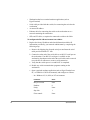
Example:
switch:admin> configupload
Server Name or IP Address [host]: 123.45.678.901
User Name [user]: kelev
File Name [config.txt]: switch1
Protocol (RSHD or FTP) [rshd]: ftp
Password:
upload complete
Restoring the System Configuration Settings
To restore the system configuration settings from a backup:
1. Verify that the RSHD service or the FTP service is running on the host
workstation (Windows or UNIX).
2. Login to the switch as the admin user.
3. Shut down the switch by entering the following command:
switchDisable
4. At the command line enter the following command:
configDownload "hostIPaddr", "user",
"path_filename","password"
where hostIPaddr is the IP address of the host computer containing
the configuration file, user is the User ID used to log into this
computer, path_filename is the path location and filename of the
Setup
23
system configuration file, and password is the password for the user ID
specified.
Note
The password operand is only required if you are using FTP.
5. Reboot the switch by entering the following command:
fastBoot
Next Steps
Specific tasks remain to be completed before the switch is fully operational
and manageable in your network with your equipment. These tasks and the
associated tools are described in the remaining documents shipped with the
product on the documentation CD-ROM. This section provides specific
guidance for completing tasks that many users may need to do.
Setting QuickLoop Mode on Ports
The default configuration for a port is fabric mode. QuickLoop is used to
connect private hosts to private storage using the Fibre Channel network. A
QuickLoop zone, connecting two switches, may be used to expand the
number of private hosts and storage connected. An entire switch can be set
to operate in QuickLoop mode using the qlEnable telnet command. A
port on a switch operating in Mixed mode can be set to or removed from
QuickLoop using the telnet commands qlPortEnable and
qlPortDisable. See the QuickLoop User’s Guide for more details.
Setting Up Speed Negotiation
The FC 16B ports can operate at three different speed levels: auto-sensing
mode, 1 Gbps mode, or 2 Gbps mode. Use the telnet command
switchCfgSpeed to set the speed level for all ports in a switch. Use the
portCfgSpeed to set the speed level for a single port. Depending on your
environment you may need to force a port to use a specific speed level.
Auto negotiation may not be supported by the device. Check the
configuration information for your network components for specific
requirements. See the Fabric OS Reference Manual for a detailed
command description.
24
Quick Start Guide
Configuring Supported Devices
HP Surestore Director FC-64 Switch
The FC 16B switch can be used with the HP Surestore Director FC-64
switch. Specific configurations must be set on both devices to make this
work.
On the FC 16B, logon to the switch with administrative privileges and enter
the following telnet commands:
1. switchDisable
2. interopMode 1
3. switchEnable
On the Director FC-64 switch, the following steps must be completed to
configure the switch for interoperability:
Step 1: Verify Unique Domain IDs
Step 2: Select a Single Surestore FC-64 Director as Principal Switch
Step 3: Verify Unique Zone Names
Step 4: Verify Brocade Product Zoning Configurations
Step 5: Verify Zone Naming Conventions
Step 6: Verify Operating Mode
Step 7: Verify Surestore FC-64 Director Switches’ Operating
Parameters
Step 8: Verify Firmware Version
Step 9: Verify EFC Manager Version
Step 10: Verify Private Loop Targets on Brocade Products are
Translated to Fabric
Step 11: Add Switches to Fabric
Step 12: Complete Zoning Activities
Step 13: Save Active Zone Set
For complete instructions on configuring the HP Director FC-64 switch see
“Checklist for Merging Fabrics” in the Merging Heterogeneous Fabrics
Instructions white paper on the FC 16B documentation CD-ROM.
Setup
25
HP Surestore VA 7400
The FC 16B also can support a 2Gb connection to an HP Surestore Virtual
Array 7400. Set the port speed to 2Gb using the telnet command
portCfgSpeed.
Use the Virtual Front Panel (VFP) on the VA 7400 and configure the device
as follows:
1. Change the controller port data rate to 2 Gbits/s
a. To change the port data rate to 2 gigabits/second for controller 1, enter:
vfpmgr -S 2 -c 1
When prompted to reset, enter no.
b. To change the port data rate for controller 2, enter:
vfpmgr -S 2 -c 2
When prompted to reset, enter no if additional settings must be
changed. If all changes have been made, enter yes to reset the array.
2. Change the controller port topology.
a. To change the port topology for controller 1 enter the following
command, selecting 4 for Direct Fabric Attach:
vfpmgr -t 4 -c 1
When prompted to reset, enter no.
b. To change the port topology for controller 2 enter the following
command, using the same topology value used for controller 1:
vfpmgr -t 4 -c 2
When prompted to reset, enter no if additional settings must be
changed. If all changes have been made, enter yes to reset the array.
Private Loop Devices
To work with private loop devices such as the FC 60, the FC 10, or the
SCSI bridge FC 4/2, set the FC 16B switch port as an L_PORT. See the
telnet command portCfgLport.
26
Quick Start Guide
3
DIAGNOSTICS
Switch Status Indicators
System activity and status can be determined through the activity of the
LEDs on the switch.
The LEDs may flash yellow during diagnostic tests; green, yellow,
or orange during POST. This is normal and does not indicate a problem
unless the LEDS do not return to a normal pattern after POST or the other
diagnostic tests are complete.
Note
The HP Surestore FC 1Gb/2Gb Switch 16B includes the following LEDs:
• 16 port status LEDs on the SFP media side (above and to the left of each
port) to indicate the status of each port.
• 16 port speed LEDs on the SFP media side (above and to the right of
each port) to indicate the current link speed of each port.
• One switch power LED below the serial port on the SFP media side, to
indicate whether the switch is on and has successfully booted.
• Two power supply LEDs on the power supply side (one on each power
supply) to indicate the status of each power supply.
27
• One switch status LED in the center of the power supply side to indicate
whether the switch is on and has successfully booted, and whether any
of the ports are faulty.
LEDs on the SFP Media Side
Figure 12 shows the SFP media side of the FC 16B with the LEDs
identified.
Switch Power LED
Ethernet Port
Serial Port
Optical Port (16x)
Port Status LED (16x)
Port Speed LED (16x)
Figure 12. The SFP Media Side of the FC 16B
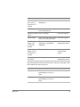
The following table describes the LEDs above each port on the left. These
LEDs indicate the status of the port.
28
Color of LED
Status of Hardware
Recommended Action
No light
No light or signal carrier
(media or cable) is detected.
Check media and
cable.
Steady green
Port is online (connected to an No action required.
external device) but has no
traffic.
Slow-flashing
green (on 1
second; off 1
second)
The port is online but
Verify correct device
segmented, indicating a
is connected to port.
loopback cable or incompatible
switch.
Quick Start Guide
Color of LED
Status of Hardware
Fast-flashing
green (on 1/4
second; off 1/4
second)
The port is in internal loopback No action required.
(diagnostic).
Flickering green
Port is online, with traffic
flowing through port.
Flashing or steady POST is running.
yellow
Recommended Action
No action required.
No action required.
Steady orange
Port is receiving light or signal No action required.
carrier, but is not yet online.
Slow-flashing
orange (on 1
second; off 1
second)
The port is disabled (result of
diagnostics or portDisable
command).
Reset the port from a
management station.
Fast-flashing
orange (on 1/4
second; off 1/4
second)
The port is faulty.
Reset the switch from
a management
station.
Alternating green Port is bypassed.
and yellow
Reset the port from a
management station.
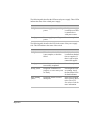
The following table describes the LEDs above each port on the right. These
LEDs indicate the speed of the port.
Diagnostics
Color of LED
Status of Hardware
Recommended Action
No light
The port is
transmitting/receiving at 1
Gbps.
No action required.
Steady green
The port is
transmitting/receiving at 2
Gbps.
No action required.
29
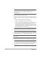
The following table describes the LEDs below the serial port. These LEDs
indicate the switch power.
Color of LED
Status of Hardware
Recommended Action
No light
Either the switch is off, or boot Verify that the switch
is not complete, or boot has
is on and boot has had
failed.
time to complete. If
there is still no light,
contact HP support.
Steady green
Switch is on and boot has
successfully completed.
No action required.
Slow-flashing
green
Diagnostic failure on one or
more ports.
Errors may be listed
in the error log. Refer
to the Fabric OS
Procedures Guide for
more information.
LEDs on the Power Supply Side
Figure 13 shows the power supply side of the switch with the LEDs
identified.
Power Supply LED (2x)
AC Power Switch (2x)
Power Supply #2
Switch Status LED
Power Supply #1
Fan Tray Assembly (containing
fans #1 and 2)
Spring Latch (2x)
Fan Tray Assembly
(containing fans #3 and 4)
Figure 13. The Power Supply Side of the FC 16B
30
Quick Start Guide
The following table describes the LEDs on each power supply. These LEDs
indicate the status of the related power supply.
Color of LED
Status of Hardware
Recommended Action
No light
Power supply is not providing
power.
Verify power supply
is on and power cable
is connected to a
valid power source.
Steady green
Power supply is providing
power.
No action required.
The following table describes the LED in the center of the power supply
side. This LED indicates the status of the switch.
Diagnostics
Color of LED
Status of Hardware
Recommended Action
No light
Either the switch is off, or boot Verify that the switch
is not complete, or boot has
is on and boot has had
failed.
time to complete. If
there is still no light,
contact HP support.
Steady green
Switch is on and boot has
successfully completed.
No action required.
Steady yellow
Diagnostic command is in
progress, or one or more ports
are faulty.
If no diagnostic tests
are running, check
the Port Status LEDs
for fault indicators.
Slow-flashing
yellow
Diagnostic failure on one or
more ports.
Errors may be listed
in the error log. Refer
to the Fabric OS
Procedures Guide for
more information.
31
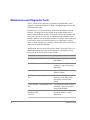
Maintenance and Diagnostic Tests
The FC 16B does not require any regular physical maintenance, and is
designed to minimize the chance of failure, including diagnostic tests and
field-replaceable units.
Diagnostic tests are provided to help troubleshoot the hardware and the
firmware. The diagnostic tests provided on the switch include tests of
internal connections and circuitry, fixed media, and any SFP modules and
fiber optic cables in use. The tests are implemented by command, either
through a telnet session or through a terminal set up for a serial connection
to the switch. Some tests require the ports to be connected by external
cables, to allow diagnostics to verify the serializer/deserializer interface, as
well as the attached SFP and cable.
All diagnostic tests are run at link speeds of both 1 Gbps and 2 Gbps. For
detailed information about the specific diagnostic tests and how to run
them, refer to the Fabric OS Procedures Guide.
Test
Command
Description
Error Log
errDump
Displays the error log without
page breaks.
Switch Offline
switchDisable
Sets the switch to offline state
necessary to run certain switch
diagnostics.
Memory Test
ramTest
Checks CPU RAM memory. Run
offline or online.
Port Register
Test
portRegTest
Checks that the registers and static
memory in each ASIC can be
successfully accessed. Run
offline.
Central Memory centralMemoryTest Checks that the central memory in
Test
each ASIC can be successfully
accessed. Run offline.
Control Message cmiTest
Interface (CMI)
Conn Test
32
Verifies that control messages can
be sent from ASIC to ASIC.
Run offline.
Quick Start Guide
Test
Command
Description
Content
camTest
Addressable
Memory (CAM)
Test
Verifies CAM functionality. Run
offline.
Port Loopback
Test
portLoopbackTest
Checks all switch main board
hardware. Frames transmitted are
looped back and received. Run
offline.
Cross Port Test
crossPortTest
Checks all switch paths. Frames
transmitted by port M are looped
back via external cable and
received at port N. Run offline or
online.
Spin Silk Test
spinSilk
Checks all switch paths at the
maximum speed of 1 Gbps.
Frames transmitted by port M are
looped back via external cables
and when received by port N are
sent again by port M in an
external loop. Run offline.
SRAM Data
Retention Test
sramRetentionTest
Verifies that data written into
ASIC memories is retained. Runs
offline.
CMem Data
Retention Test
CmemRetentionTest Verifies that data written into
ASIC SRAMs is retained. Runs
offline.
Switch Online
switchEnable
Returns switch to online state.
The transmit and receive speed of the links may be temporarily
locked to a specific speed during diagnostic testing.
Note
Diagnostics
33
Error Messages
To analyze error messages, access the error message log via a Telnet
session using the errDump command. Note any messages before removing
power from the switch; error messages are stored in RAM and are lost
when power is removed. See the Fabric OS Reference Manual for a
detailed description of each message.
Getting Support
Service and Support
There are no customer serviceable parts in the FC 16B. For the most current
technical support information for the FC 16B, visit the HP Web site at
www.hp.com/support/fc16B.
Additional Licenses
For information on obtaining license keys visit the HP Web site at
www.hp.com/support/fc16B.
34
Quick Start Guide
4
SPECIFICATIONS
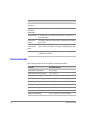
General
The following table lists the general specifications for the HP Surestore FC
1Gb/2Gb Switch 16B.
Specification
Description
Fabric
initialization
Complies with FC-SW 5.0
IP over Fibre
Channel
(FC-IP)
Complies with FC-IP 2.3 of the FCA profile
System
architecture
Non-blocking shared-memory switch
System
processor
Intel 80960VH, 100MHz CPU
Number of
16 SFP ports
Fibre Channel
ports
Fibre Channel 1 or 2 Gbps full duplex
port speed
35
Specification
Description
Modes of
operation
Fibre Channel Class 2 and Class 3
Aggregate
switch I/O
bandwidth
64 Gbps if all 16 ports running at 2 Gbps, full duplex
Frame buffers 27 buffers per E_Port and 16 buffers per F_Port at 2112
bytes per frame
Port to port
latency
Less than 2 microseconds with no contention (destination
port is free)
Data
transmission
range
Up to 500 m (1,625 ft.) for short-wavelength optical link
Up to 10 km (32,820 ft.) for long-wavelength optical link
Chassis type
Forced-air cooling that flows from the power supply side
to the SFP media side
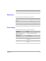
Environmental
The following table lists the acceptable environmental ranges.
36
Condition
Acceptable Range
Temperature (operating)
10°C to 40°C
Temperature (non-operating)
-35°C to 65°C
Humidity (operating)
5% to 85% RH non-condensing, at 40°C
Humidity (non-operating)
0% to 90% RH non-conducting, at 40°C
Altitude (operating)
0 to 3 kilometers above sea level
Altitude (non-operating)
0 to 12 kilometers above sea level
Shock (operating)
4 G, 11 MS duration, half sine
Shock (non-operating)
20 G, 11 MS duration, sq. wave
Vibration (operating)
5 G, 0-3 kHz at 1.0 octave/minute
Quick Start Guide
Condition
Acceptable Range
Vibration (non-operating)
10 G, 0-5 kHz at 1.0 octave/minute
Dimensions
The following table lists the dimensions of the FC 16B.
Dimension
Value
Height
1U
Depth
24 inches (61.0 cm)
Width
17 inches (43.2 cm)
Weight (with both power supplies installed)
28.5 lbs (12.9 kg)
Power Supply
The following table lists the power supply specifications.
Specifications
Specification
Value
Total power available from
each power supply
126 Watts, with fans operating
Input voltage
100 - 240 VAC
Input line frequency
47 - 63 Hz
Harmonic distortion
Active power factor correction per
IEC1000-3-2
BTU rating
108 Watts x 3.412 BTU/Hr/Watts = 368.5
BTU/Hr
37
38
Quick Start Guide
PRODUCT REGULATORY INFORMATION
FCC EMC Statement (USA)
This equipment has been tested and found to comply with the limits for a Class A
digital device, pursuant to Part 15 of the FCC Rules. These limits are designed to
provide reasonable protection against harmful interference when the equipment is
operated in a commercial environment. This equipment generates, uses and can
radiate radio frequency energy and, if not installed and used in accordance with the
instruction manual, may cause harmful interference to radio communications.
Operation of this equipment in a residential area is likely to cause harmful
interference, in which case the user will be required to correct the interference at
his own expense. The end user of this product should be aware that any changes or
modifications made to this equipment without the approval of Hewlett-Packard
could result in the product not meeting the Class A limits, in which case the FCC
could void the user's authority to operate the equipment.
EMC Statement (Canada)
This Class A digital apparatus meets all requirements of the Canadian
Interference-Causing Equipment Regulations.
Cet appareil numérique de la Classe A respecte toutes les exigences du Règlement
sur le matériel brouilleur du Canada.
EMC Statement (European Union)
This is a Class A product. In a domestic environment this product may cause radio
interference, in which case the user may be required to take adequate measures.
Spécification ATI Classe A (France)
DECLARATION D'INSTALLATION ET DE MISE EN EXPLOITATION d'un
matériel de traitement de l'information (ATI), classé A en fonction des niveaux de
perturbations radioélectriques émis, définis dans la norme européenne EN 55022
concernant la Compatibilité Electromagnétique.
39
Germany Noise Declaration
Schalldruckpegel Lp = 46.1 dB(A)
Am Arbeitsplatz (operator position)
Normaler Betrieb (normal operation)
Nach ISO 7779:1999 (Typprüfung)
VCCI EMC Statement (Japan)
Harmonics Conformance (Japan)
BSMI EMC Statement (Taiwan)
RRL EMC Statement (Korea)
40
Quick Start Guide
Laser Safety
A. Certification and Classification Information
When equipped with native Fibre Channel adapters, this product contains a laser
internal to the small form factor pluggable (SFP) transceiver modules.
In the USA, the SFP module is certified as a Class 1 Laser product, conforming to
the requirements contained in Department Of Health and Human Services (DHHS)
regulation 21 CFR, Subchapter J. The certification is indicated by a label on the
metal SFP housing.
Outside the USA, the SFP is certified as a Class 1 Laser product conforming to
requirements contained in IEC 825-1:1993 and EN60825-1:1994, including
Amendment 11:1996.
The SFP includes the following certifications:
•
UL Recognized Component (USA)
•
CSA Certified Component (Canada)
•
TUV Certified Component (European Union)
•
CB Certificate (Worldwide)
The following figure shows the Class 1 information label that appears on the metal
housing of the SFP.
CLASS 1 LASER PRODUCT 21 CFR(J)
B. Product Information
Each communications port consists of a transmitter and receiver optical
subassembly. The transmitter subassembly contains internally a semiconductor
laser diode in the wavelength of either 850 nanometers (shortwave laser) or 1310
nanometers (longwave laser).
Class 1 Laser products are not considered hazardous.
WARNING There are no user maintenance operations, service operations, or
adjustments to be performed on the SFP module.
C. Usage Restrictions
Failure to comply with these usage restrictions may result in incorrect operation of
the system and points of access may emit laser radiation above the Class 1 limits
established by the IEC and U.S. DHHS.
Product Regulatory Information
41
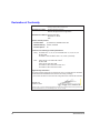
Declaration of Conformity
DECLARATION OF CONFORMITY
according to ISO/IEC Guide 22 and EN 45014
Manufacturer's Name:
Hewlett-Packard Company
Network Storage Solutions Organization
Manufacturer's Address: 8000 Foothills Blvd.
Roseville, CA 95747
USA
declares, that the product
Product Name:
hp surestore fc 1Gb/2Gb switch 16B
Model Number(s):
A7340A, A7340AZ
Product Options:
All
conforms to the following Product Specifications:
Safety: IEC 60950:1991 + A1, A2, A3, A4 / EN 60950:1992 + A1, A2, A3, A4, A11
GB 4943-1995
IEC 60825-1:1993 / EN 60825-1:1994 + A11, Class 1 (Laser/LED)
EMC:
1
CISPR 22:1997 / EN 55022:1998 Class A
GB 9254-1988
CISPR 24:1997 / EN 55024:1998
IEC 61000-3-2:1995 / EN 61000-3-2:1995 +A14
IEC 61000-3-3:1994 / EN 61000-3-3:1995
Supplementary Information:
The product herewith complies with the requirements of the Low Voltage Directive 73/23/EEC
and the EMC Directive 89/336/EEC and carries the CE marking accordingly.
1) The Product was tested in a worst-case test configuration which maximizes RFI emissions.
Roseville, CA
October 15, 2001
European Contact: Your local Hewlett-Packard Sales and Service Office or Hewlett-Packard GmbH, Department HQTRE, Herrenberger Straße 130, D-71034 Böblingen (FAX: + 49-7031-14-3143)
42
Quick Start Guide
Technical information in this document
is subject to change without notice.
© Copyright Hewlett-Packard Company 2001.
All right reserved.
Reproduction, adaptation, or translation
without prior written permission is prohibited
except as allowed under the copyright laws.
Printed in U.S.A.
E1201
Manual Part Number
A7340-96002
*A7340-96002*