1
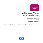
AB465A PCI-X 2-Port 2 Gigabit Fibre Channel and 2-Port Gigabit Ethernet Combination Card Installation Guide For fcd Driver Versions B.11.11.04 and B11.23.02 and For igelan Driver Versions B.11.11.17 and B.11.23.05 HP 9000 and HP Integrity Systems Manufacturing Part Number : AB465-90001 E0205 U.S.A. © Copyright 2005 Hewlett-Packard Development Company L.P. Legal Notices The information in this document is subject to change without notice. Hewlett-Packard makes no warranty of any kind with regard to this manual, including, but not limited to, the implied warranties of merchantability and fitness for a particular purpose. Hewlett-Packard shall not be held liable for errors contained herein or direct, indirect, special, incidental or consequential damages in connection with the furnishing, performance, or use of this material. Warranty A copy of the specific warranty terms applicable to your Hewlett- Packard product and replacement parts can be obtained from your local Sales and Service Office. Restricted Rights Legend Use, duplication or disclosure by the U.S. Government is subject to restrictions as set forth in subparagraph (c) (1) (ii) of the Rights in Technical Data and Computer Software clause at DFARS 252.227-7013 for DOD agencies, and subparagraphs (c) (1) and (c) (2) of the Commercial Computer Software Restricted Rights clause at FAR 52.227-19 for other agencies. HEWLETT-PACKARD DEVELOPMENT COMPANY L.P. 20555 S.H. 249 Houston, Texas 77070 Use of this document and any supporting software media supplied for this pack is restricted to this product only. Additional copies of the programs may be made for security and back-up purposes only. Resale of the programs, in their present form or with alterations, is expressly prohibited. Copyright Notice Copyright 1997-2005 Hewlett-Packard Development Company L.P. All rights reserved. Reproduction, adaptation, or translation of this document without prior written permission is prohibited, except as allowed under the copyright laws. Trademark Notices UNIX is a registered trademark in the United States and other countries, licensed exclusively through The Open Group. Itanium, Itanium2, and Intel are registered trademarks of Intel Corp. HP Serviceguard and Superdome are registered trademarks of Hewlett-Packard Co. Product Name Also Known As The description of this AB465A product on the price list is “HP PCI-X 2p 2Gb FC and 2p 1000BT Adptr.” For additional clarity and for use in some tasks, the name may appear slightly differently. Combined technologies are sometimes called “combination” or “multifunction” in an adapter or card. 1000Base-T is also commonly called 1000BT or Gigabit Ethernet. This Installation Guide has been translated to: http://www.docs.hp.com/ja/index.html 2 Hardware and Software Installation Procedure Step 1: Access the system card bay Hardware and Software Installation Procedure These instructions apply to AB465A PCI-X 2-Port 2 Gigabit Fibre Channel and 2-Port Gigabit Ethernet combination cards which can operate on HP-UX 11i v 1.0 of December 2004 or HP-UX 11i v 2.0 of September 2004 or later. If your system is running HP-UX 11i v 1.0, you can find the 11i v 1.0 LAN and fibre channel driver bundles on the December 2004 OE distribution media. For 11i v 1.0, you can either load the entire OE or just the two driver bundles for this card. If loading this product on 11i v 2.0, you need to load the entire HP-UX 11i v 2.0 September 2004 OE from the distribution media and you will automatically get the correct LAN and fibre channel driver bundles. Note: if your LAN card was factory installed (ordered on product option 0D1), you do not need to perform the following hardware and software installation steps though you still need to configure the card’s IP address as well as set other parameters and options such as those mentioned in Table 2 The Network Configuration Worksheet. These AB465A combination cards can be added to your system or replaced without the need to shut down or reboot the system--a process called online addition and replacement (OLAR). The following instructions assume you are not performing online addition and replacement. Step 1: Access the system card bay • If the system is running, first, issue the sync command. Then shut down the system by executing: shutdown -h. Respond “y” to the continue to shutdown prompt. • Wait for the system to shut down completely, and then power off the system by pressing the system off button. Ensure that the system is grounded. • Open the system to gain access to the PCI backplane. • Select an empty PCI or PCI-X slot and remove the slot cover. The card can operate in PCI as well as PCI-X mode. Some servers have “shared” slots. If you put this card in a shared slot that is shared with a slower card, both cards will then operate at the slower card’s speed. Step 2: Install the card • Check the latest support matrix to see the systems that support this card, how many cards per system, and if any software updates are needed, The support matrix is available on the web at http://docs.hp.com under “Networking and Communications.” • Observe the antistatic precautions. HP recommends wearing ESD straps when installing the card. • Record the serial number and MAC address located on the card for future reference. The MAC address labelled on the card refers to LAN port A. Add 1 to obtain the MAC address for LAN port B. For fibre channel, also record the card’s Port and Node worldwide names (WWN). The WWN labelled on each card refers to WWN for FC port 1 (the left port). Add 2 to obtain the WWN for FC port 2 (the right port). • Grasp the card by its edges or faceplate with both hands, insert the card into the slot, and firmly but gently press the card in until it is fully seated. • Secure the card and reassemble the system. Step 3: Connect the card to the network • Attach the connector from a LAN cable to the card (Figure 1 on page 11). Do the same for the second port. For 1000Base-T, cabling must be Cat 5 UTP or better with RJ-45 connectors. For operating distances, refer to the “Cable Specifications” section of this document. Note: LAN A is the bottom RJ-45 connector. 3 Hardware and Software Installation Procedure Step 4: Connect the fibre channel devices • Attach the free end of the LAN cable to any unused port on the switch. The Base-T connections on the card operate at 10 or 100 Mbit/s in either full- or half-duplex modes and at 1000 Mbit/s only in full-duplex mode. Set the ports on the card and on your switch according to the following table. Table 1 HP-UX 1000Base-T Supported Configurations HP-UX 1000Base-T Port Link Partner Resulting Speed AUTO AUTO Highest Common Speed (HP-UX supports 10/100/1000) AUTO 1000 FD fixed/manual 1000 Mbit/s FD 10 HD 10 HD (for example, a 10Base-T Hub) 10 Mbit/s HD 10 FD 10 FD 10 Mbit/s FD 100 HD 100 HD 100 Mbit/s HD 100 FD 100 FD 100 Mbit/s FD If you are using Jumbo Ethernet frames, ensure that: — all end stations on a given LAN1 have the same maximum transmission unit (MTU) setting. — intermediate stations such as switch ports in your LAN have an MTU equal to or greater than the end station’s MTU. Step 4: Connect the fibre channel devices • Attach the LC connector from a fibre channel cable to the fibre channel connector on the card (Figure 1). For fibre channel, the cable must be 50 micron MMF. If the remote connection is type SC, you will need an LC-to-SC cable. Do the same for the other connector. • Plug the other end of the fibre channel cable into the connector on your fibre channel switch or device. Step 5: Prepare to install the software • Ensure power cable is connected to system. Power up the system. • Log in as root. • Check that the /usr/bin, /usr/sbin, and /sbin directories are in your PATH using the command: echo $PATH • Check the HP-UX version by entering: uname -r # uname -r B.11.11 or B.11.23 The version must be B.11.11 for 11i v 1.0 or B.11.23 for 11i v 2.0. 1. In the Jumbo Frames discussion, “LAN” means that the end stations do not have any routers or layer 3 switches in between them. 4 Hardware and Software Installation Procedure Step 6: Install the latest software. • Check the Release Notes for GigEther-01 and FibrChanl-01 to see if you need to install any appropriate patches for your system. Release Notes are available on the Web at http://docs.hp.com under Networking and Communications. Step 6: Install the latest software. • Load the software media into the appropriate drive. If you are adding the Gigabit Ethernet software bundle (GigEther-01) for HP-UX 11i v 1.0, you can get the Gigabit Ethernet driver on the December 2004 (or later) OE distribution media. If loading this product for 11i v 2.0 for the first time, you must load the entire September 2004 (or later) OE distribution media and you’ll get the needed drivers. Once you’ve got the required full HP-UX OE installed, you will be able to select and load just the driver bundle if you want. • Run the swinstall program to install the software using the command: swinstall. • Change the host name after “Source Host Name,” if necessary. • Click the Source Depot Path to identify the registered depot for the appropriate source depot path and activate the OK button to return to the Software Selection Window. • Highlight the 1000Base-T software GigEther-01 (for cards such as AB465A). • Choose Mark for Install from the “Actions” menu to choose the product to be installed. • Choose Install from the “Actions” menu to begin product installation and open the Install Analysis Window. • Activate the OK button in the Install Analysis Window when the Status field displays a “Ready” message. • Activate the YES button at the Confirmation Window to confirm that you want to install the software. swinstall loads the fileset, runs the control scripts for the filesets, and builds the kernel. This should take about 3 to 5 minutes. When the status field indicates Ready, click Done. A Note Window then opens. Click the OK button to reboot the system. • If you are adding the fibre channel software bundle (FibrChanl-01) for 11i v 1.0, you can find the fibre channel software bundle on the December 2004 (or later) OE distribution media. If you are adding the fibre channel software bundle (FibrChanl-01) for 11i v 2.0, you can find the fibre channel software bundle on the September 2004 (or later) OE distribution media. Just repeat Step 6 to load it. Step 7: Configure the card using SAM • Log in as root and verify that the card and its hardware path are displayed by entering: ioscan. • Run the System Administration Manager by entering sam. • Double-click Networking and Communications. • Double-click Network Interface Cards. • Highlight the AB465A combination Fibre Channel/Gigabit Ethernet card and choose Configure from the “Actions” menu. • Fill in the form according to the instructions using the “Network Configuration Worksheet” in this document. • Click the OK button to activate the card and then select exit from the “File” menu until you exit SAM. 5 Hardware and Software Installation Procedure Step 8: Verify the fibre channel installation Step 8: Verify the fibre channel installation • To verify that the fc driver appears for each installed card, enter: ioscan -fk The ioscan output might look like the following: Class I H/W Path Driver S/W State H/W Type Description fc 4 1/0/8/1/0/4/0 fcd CLAIMED INTERFACE HP AB465-60001 PCI/PCI-X 2-port 2Gb FC/2-port 1000B-T Combo Adapter (FC Port 1) fc 5 1/0/8/1/0/4/1 fcd CLAIMED INTERFACE HP AB465-60001 PCI/PCI-X 2-port 2Gb FC/2-port 1000B-T Combo Adapter (FC Port 2) The last two digits of the hardware path (third column) reflect the path of each port. Both ports need to show as CLAIMED here. • Verify that all devices you attached to the fibre channel card are listed in the ioscan output. For example, if you have a direct attach fibre channel device attached to the system, the ioscan output might look like: 8/12.8.0.255.0.1.0 sdisk CLAIMED DEVICE DGC C3400WDR5 The example above is the hardware path of LUN0 of a directly attached fibre channel mass storage device with loop ID of 1. If all attached devices are not listed, or for details on interpreting hardware paths, see the HP Fibre Channel Mass Storage Adapters Support Guide. HP fibre channel installation is verified if the ioscan output lists all mass storage devices attached to the card. If the correct driver is installed, but the card does not show in the ioscan output, the driver is not recognizing the card. Make sure the card is seated and connectors are attached tightly, then if the problem persists, contact HP for assistance. Step 9: Verify the LAN installation • Verify that the LAN connector’s Link LED is steadily on (this means the card and driver are installed successfully). • Obtain the PPA number and the station address of each card by using the lanscan command. The MAC address labelled on each card refers to LAN port A (the right port). Add 1 to obtain the MAC address for LAN port B. • To verify link-level connectivity with a remote system, enter: $ linkloop -i PPA_number remote_station_address Note: when you use linkloop, ensure that the remote system is on the same subnet and is an HP-UX-based system. • To verify IP-level connectivity with a remote system, enter: $ping Remote_IP_Address and netstat -in When you use netstat -in, the output values Ipkts and Opkts should be incrementing. 6 Hardware and Software Installation Procedure Optional Step: Configure Jumbo Frames Size (Jumbo frames are supported only at 1000 Mbit/s) • Installation is complete when you have successfully run linkloop, ping and netstat. To configure remote systems, see the Ethernet Support Guide available on the web at http://docs.hp.com. Do this step only if remote systems have not been previously configured. • Optionally, if you want to verify that the igelan driver appears for each installed card, enter: ioscan -fknClan The ioscan output for each port would look something like the following: Class I H/W Path Driver S/W State lan 6 1/0/2/1/0/6/0 igelan CLAIMED FC/2-port 1000B-T Combo Adapter H/W Type Description INTERFACE HP AB465-60001 PCI/PCI-X 2-port 2Gb The last two digits of the hardware path (third column) reflect the path of each port -- in the sample output shown, the “0” indicates LAN A (as shown in Figure 1 on page 11). Both ports need to show as CLAIMED here. Optional Step: Configure Jumbo Frames Size (Jumbo frames are supported only at 1000 Mbit/s) • Jumbo frames for the igelan driver on HP-UX 11i v 1.0 have an mtu_size of 9000 bytes. On HP-UX 11i v 2.0 of September 2004, jumbo frames using the igelan driver can have an MTU in the range of 1501 to 9000 bytes. If you are using Jumbo Ethernet frames, ensure that: — all end stations on a given LAN1 have the same maximum transmission unit (MTU) setting; — intermediate stations such as switch ports in your LAN have an MTU equal to or greater than the end station’s MTU. • Obtain the PPA number of the card by entering lanscan. • Choose one of two configuration methods that will permanently save your configuration. — use the GUI-based system admin manager (SAM). To use SAM, type sam at the HP-UX system prompt; then double-click Networking and Communications, and then Advanced Configuration--see Ethernet Support Guide for details, and then do the steps for verifying the MTU size; or edit the following configuration file using an editor such as “vi”: /etc/rc.config.d/hpigelanconf. Set the mtusize by editing: HP_IGELAN_MTU[i]=mtusize, and insert the proper interface name: HP_IGELAN_MTU[i]=HP_IGELAN_INTERFACE_NAME. When the system reboots, the interface will be configured for jumbo frame operation. • Verify MTU change by entering netstat -rn. If MTU has not changed, enter the following commands: $ifconfig lan PPA_number unplumb $ifconfig lan PPA_number ip_address netmask netmask up • To check (or verify) the current Ethernet frame size, enter: $lanadmin -m PPA_number 1. In the Jumbo Frames discussion, “LAN” means that the end stations do not have any routers or layer 3 switches in between them. 7 Hardware and Software Installation Procedure For Further Information An alternative way to temporarily configure jumbo frame size is to enter: lanadmin -M mtu_size PPA_number. Using lanadmin is temporary because it will not preserve your settings across reboots. The PPA_number is the one we obtained from the output of lanscan. For using Jumbo Frames with the igelan Gigabit Ethernet driver on HP-UX 11i v 1.0, set the mtu_size to 9000 (bytes). For using Jumbo Frames with the igelan driver on 11i v 2.0 of September 2004 (or later), set the mtu_size to a number in the range of 1501 to 9000 bytes. For Further Information For further information on the Gigabit Ethernet and Fibre Channel as implemented in this card, please refer to http://docs.hp.com and then look under Networking and Communications. This card’s information is primarily located under the subsection called “Combination Cards.” The AB465A is a 2-port FC and 2-port GigE version of HP’s A9784A combination card; and they both use the same drivers and firmware -- the drivers are fcd for Fibre Channel and igelan for Gigabit Ethernet. To check for updated information, either look at the information for the A9784A or check the Fibre Channel Support Matrix and the Ethernet Support Matrix on http://docs.hp.com Maintenance and troubleshooting information about the igelan Gigabit Ethernet driver used in this product is located in the Ethernet Support Guide. There is maintenance and troubleshooting information about the fcd Fibre Channel driver used in this product in the HP Fibre Channel Mass Storage Adapters Support Guide. There is also a Support Matrix for Gigabit Ethernet and a separate one for Fibre Channel. The fcd driver is the same one used in the A6826A Fibre Channel product and has the same features as the driver described in that product’s documentation. 8 Hardware and Software Installation Procedure Network Configuration Worksheet Network Configuration Worksheet Fill out one worksheet for the networking data of each LAN port on the combination card you are installing. Table 2 Data Type Network Configuration Worksheet Required/ Optional Default How to Configure (see Note 1) Example Internet Address Required 0.0.0.0 SAM or ifconfig or edit /etc/rc.config.d/ netconf 196.6.20.2 Subnet mask Required if using subnetting Subnet mask not used SAM or ifconfig or edit /etc/rc.config.d/ netconf 255.255.248.0 Station address Built-in but can be optionally changed As shown on card SAM or edit /etc/rc.config.d/ hpigelanconf or temporarily: lanadmin -A 0x0060b0c4012f Host name alias for this network interface (card) Required if the system is connected to more than 1 network None SAM or edit /etc/hosts host1 Link configuration Required Autonegotiating SAM or temporarily: lanadmin -X lanadmin -X auto_on ppa# (if already turned off) Link speed/duplex mode Required Autonegotiating Hub or switch (see Note 2) SAM or temporarily: lanadmin -X lanadmin -X 100fd ppa# MTU (Maximum Transmission Unit): Jumbo Frames Optional 1500 bytes SAM or edit /etc/rc.config.d/ hpigelanconf or temporarily: lanadmin -M lanadmin -M 9000 ppa# (see Note 3 below) Receive flow control Optional On SAM or edit /etc/rc.config.d/ hpigelanconf or temporarily: lanadmin -X lanadmin -X fctrl off Your System Note 1: To configure values permanently, edit the configuration files using SAM or an editor such as “vi”. Using lanadmin will not preserve your settings across reboots. Note 2: The speed configuration of the card can be 10, 100, or 1000 Mbit/s and is determined by the speed setting of the hub or switch port to which the card is connected. The card automatically senses this speed. The Base-T card only runs at one speed at a time. To verify the speed selection, run lanadmin -x ppa#. 9 Hardware and Software Installation Procedure Cable Specifications Note 3: The valid MTU size for normal frames using the igelan driver on HP-UX 11i v 1.0 or v 2.0 is 1500 bytes. For Jumbo Frames, the valid MTU size on HP-UX 11i v 1.0 is 9000 , and for HP-UX 11i v 2.0, it is a number in the range of 1501 to 9000 bytes. Cable Specifications Operating Distance for 1000Base-T (Copper UTP): Up to 100 meters — Cat 5 and Cat 5E Operating distances for fibre channel using multi-mode fiber optic cable are as follows: Description (Fibre Channel) 50/125 micron MMF 50 micron MMF Rate 2 Gbits/s 1 Gbits/s Operating Distance 300 meters (984 ft) 500 meters (1640 ft) Available HP Fiber Optic Cables: LC-LC C7524A C7525A C7526A LC-SC C7529A C7530A Adapter/Extenders C7534A Adapter Kit C7540A 10 Fibre Channel Cable 2m LC duplex 50/125 M/M Optical Fibre Channel Cable 16m LC duplex 50/125 M/M Optical Fibre Channel Cable 50m LC duplex 50/125 M/M Optical Fibre Channel Cable 2m LC-SC duplex 50/125 M/M Optical Fibre Channel Cable 16m LC-SC duplex 50/125 M/M Optical Fibre Channel Adapter SC Form Factor Fibre Optic Adapter Kit - Optical: Includes 2m LC/SC Cable and F/F extender Hardware and Software Installation Procedure Figure 1 AB465A PCI-X 2-Port 2Gb FC/ 2-Port 1000B-T Combination Card Port 1 Speed LEDS (Port 1) Fibre Channel Connectors (Duplex LC) Speed LEDS (Port 2) 1Gb 2Gb 2Gb 1Gb Port 2 LAN B } Activity/Link LEDs Flashing = Data traffic Solid = Active link OFF = No link 1000Base-T Connectors (RJ-45) LAN A PCI-X 133 MHz Speed LEDs Off = 10 Mbit/s Green = 100 Mbit/s Yellow = 1000 Mbit/s 11 Hardware and Software Installation Procedure Features Features The AB465A PCI-X Combination cards have the following features: • PCI-X 133 MHz capable card. It can operate at 32-bit or 64-bit compatible modes and is supported in the following frequencies: PCI 66, PCI-X 66, and PCI-X 133. Best performance is achieved by putting the card in a “dual-rope” PCI-X 133 slot. To identify which slots are the dual rope slots in a particular system, please refer to the hardware users’ guide for each system. The AB465A card is not supported in PCI 33 bus mode. It operates in 3.3V slots only. • Supports HP-UX 11i v 2.0 (64 bit) of September 2004 (or later) or 11i v 1.0 of December 2004 (or later) on HP 9000 (PA-RISC-based) and HP Integrity (Itanium or Itanium2-based) platforms. • The Gigabit Ethernet ports support use of Jumbo Frames. • Supports HP Serviceguard and Auto-Port Aggregation (APA) for high availability. • The Gigabit Ethernet port supports virtual LANs (VLANs). This feature is described in Using HP-UX VLANs on http://docs.hp.com. • Supports PCI-X online addition/replacement (OLA/R) on specified systems.For instructions on how to perform online addition and replacement (OLAR) for PA-RISC-based systems running HP-UX 11i v 1.0, see Configuring HP-UX For Peripherals. For instructions on performing OL* for Itanium-based systems and PA-RISC systems running HP-UX 11i v 2.0 of September 2004 or later, refer to the Interface Card OL* Support Guide. • Supports configuration through SAM or command line. • vPars support with vPars 3.02 on supported HP 9000 (PA-RISC-based) systems. Boot over vPars is supported only on the Fibre Channel ports. • Supports 16k LUNs on the Fibre Channel ports. • Supports boot/dump on Fibre Channel ports only. • Online/Offline Diagnostics. • Ignite UX support. • Supports readout of Vital Product Data (VPD) for Fibre Channel. To read the Fibre Channel VPD, use: fcmsutil devicefilename vpd. • Firmware for the Fibre Channel ports -- version is 3.3.150 as of the publication of this document. The FC EFI driver firmware version is 1.42. For GigE, the bootcode is version 3.27; EFI is v7.0.10 or later. To check for updates of these, see the section “For Further Information” in this document. • Fibre channel transfer rates of 2Gbit/s and 1Gbit/s • Auto speed sensing on the Fibre Channel ports. • Supports Fibre Channel protocols SCSI-FCP-2 and FC-Tape. • Supports the following Fibre Channel topologies: — FC-SW — FC-AL-2 — FC-FLA — FC-PLDA 12 Hardware and Software Installation Procedure Interoperability: Supported Systems Interoperability: Supported Systems Supported Systems The combination card is supported in the HP Integrity (Itanium or Itanium2-based) systems specified in Table 3. Table 3 Combination Card in HP Integrity Systems rx1600, rx1620 ; These servers accommodate 1 AB465A per system. rx2600 rx2620 rx4640 rx7620 HP Integrity Superdome IA 16-way, 32-way, 64-way, and 128-way rx8620 and rx8620 with I/O Expansion unit The combination card is supported in the HP 9000 (PA-RISC processor-based) systems specified in Table 4. Table 4 Combination Card in HP 9000 Systems rp3410-2 rp3440-4 rp4440-8 rp7420-16 HP 9000 Superdome (3.3 volt slots) PA 16-way, 32-way, 64-way, and 128-way rp8420 and rp8420 with I/O Expansion unit 13 Card Physical and Environmental Specs and Regulatory Information Card Physical and Environmental Specifications Card Physical and Environmental Specs and Regulatory Information Card Physical and Environmental Specifications Following are the product physical and environmental specifications of the AB465A PCI-X 2-Port 2 Gigabit Fibre Channel and 2-Port Gigabit Ethernet Combination Card. Physical Specifications Form Factor PCI-X (rev 2.3) full-height card PCI support 64-bit 3.3V only 133Mhz Height 10.668 cm (4.2 in) Depth 16.9 cm (6.6 in) Width 1.295 cm (0.51 in) Weight 0.18 kg (0.4 lb) kg Electrical Power consumption: 25 Watts Environmental Temperature Degrees F = (1.8 x Degrees C) + 32 Operating Temperature Range (Degrees Celsius) +5o C to 40o C Recommended Operating Temperature Range (Degrees Celsius) +10o C to 30o C Non-operating/ storage Temperature Range (Degrees Celsius) -40o C to 70o C Temperature Shock Immunity - Max Rate of Change 20 C/hr Non-operating/storage Humidity Range in %RH 90 Recommended Operating Humidity Range @ 22 Degrees Celsius in %RH 40 to 60 Heat Dissipation (in Watts) 17 Maximum kV (if less than 15 kV) with no loss of function 8 Maximum kV (if less than 25 kV) with no component damage 25 14 Card Physical and Environmental Specs and Regulatory Information Card Physical and Environmental Specifications Operating Altitude 3,000 meters (9900) ft Non-operating Altitude 4,500 meters (14850 ft) Electromagnetic Compatibility This document contains regulatory statements for the United States and the European community. 15 Card Physical and Environmental Specs and Regulatory Information FCC Statement (For U.S.A.) FCC Statement (For U.S.A.) Federal Communications Commission Radio Frequency Interference Statement WARNING This device complies with Part 15 of the FCC rules. Operation is subject to the following two conditions: (1) This device may not cause harmful interference and (2) this device must accept any interference received, including interference that might cause undesired operation. This equipment has been tested and found to comply with the limits for a Class A digital device, pursuant to Part 15 of the FCC rules. These limits are designed to provide reasonable protection against harmful interference when the equipment is operated in a commercial environment. This equipment generates, uses and can radiate radio frequency energy, and, if not installed and used in accordance with the instruction manual, may cause harmful interference to radio communications. Operation of this equipment in a residential area is likely to cause interference, in which case the user at his own expense will be required to take whatever measures may be required to correct the interference. Hewlett-Packard’s system certification tests were conducted with HP-supported peripheral devices and cables, such as those received with your system. Changes or modifications to this equipment not expressly approved by Hewlett-Packard could void the user’s authority to operate the equipment. Canada Warning: This Class A digital apparatus meets all requirements of the Canadian Interference-Causing Equipment Regulations. Cet appareil numérique de la classe A respecte toutes les exigences du règlement sur le matériel brouilleur du Canada. EMI Statement (European Community) NOTE 16 This is a Class A product. In a domestic environment, this product may cause radio interference, in which case you may be required to take adequate measures. Card Physical and Environmental Specs and Regulatory Information Laser Safety Statements Laser Safety Statements Laser Safety Statements - U.S. FDA/CDRH - Optical (laser) Transceiver CAUTION The optical transceiver provided on the network interface card contains a laser system and is classified as a “Class-I Laser Product” under a U.S. Department of Health and Human Services (DHHS) Radiation Performance standard according to the Radiation Control for Health and Safety Act of 1968. The Class I label and compliance statement are located on the optical transceiver. To ensure proper use of this product, please read this instruction manual carefully and retain for future reference. Should the unit ever require maintenance, contact an authorized service location. CAUTION Use of controls, adjustments or the performance procedures other than those specified herein may result in hazardous radiation exposure. To prevent direct exposure to laser beam, do not try to open the enclosure. Laser Safety - European Union - Optical Transceiver Only CAUTION The optical transceiver provided on the network interface card contains a laser system and is classified as a “Class 1 Laser Product” per EN 60825-1, Safety of Laser products. Class 1 laser products are considered safe and do not pose a biological hazard if used within the data sheet limits and instructions. To ensure proper use of this product, please read this instruction manual carefully and retain for future reference. Should the unit ever require maintenance, contact an authorized service location. CAUTION Use of controls, adjustments or the performance procedures other than those specified herein may result in hazardous radiation exposure. To prevent direct exposure to laser beam, do not try to open the enclosure. There are no user serviceable parts nor any maintenance required for the optical transceiver. All adjustments are made at the factory before shipment to customers. Tampering with or any attempt to modify the optical transceiver will result in voided product warranty. It may also result in improper operation of the network card circuitry and possible overstress of the laser source. Device degradation or product failure may result. 17 Card Physical and Environmental Specs and Regulatory Information Laser Safety Statements 18