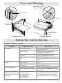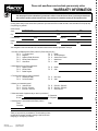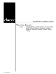
1
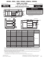
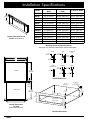
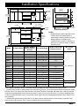
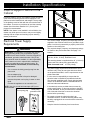
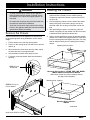
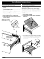
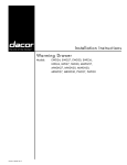
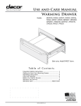
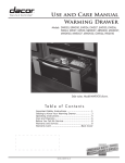
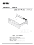
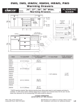
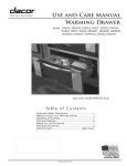
ERWD, EWD, IWD, MRWD, MWDV, MWDH, OWD and PWD Document # PG02 - 002 Revised 11/19/09 24”, 27”, 30”, 36”, Wide Warming Drawers Product tolerances: ±1/16” (±1.6 mm) unless otherwise stated ERWD EWD 3 1/2" (89 mm) 3 7/16" (87 mm) 1 1/8" (29 mm) 1" (25 mm) PLANNING GUIDE Electrical Circuit Required Total Connected Load 120 Vac, 60 Hz, 15 Amps. grounded, dedicated circuit 4.0 Amps. @ 120 Vac, 60 Hz MRWD30B (only) 1 7/16" (37 mm) 1" (25mm) All other MRWD series Page 1/3 10 1/8" (257 mm) MWDH/V 3 1/4" (83 mm) 1" (25 mm) PWD 2 1/4" (57 mm) A 1" (25 mm) Handle Dimensions - side view Drawer Face Dimensions (MWD Series Shown) B C Chassis Mounting Hole 9 Places 40" (1016 mm) 3 prong 120 Vac power cord 9" (229 mm) 1/2" (13 mm) 23 3/8" (594 mm) 10" (254 mm) Chassis without drawer inserted 5/64" (2mm) Drawer open 1/2" (13 mm) 23 13/16 (605 mm) Chassis Dimensions (A) Drawer Face Width (B) Chassis Face Width (C) Chassis Width ERWD30 30” (762 mm) 29 5/8” (752 mm) 28 1/4” (718 mm) EWD24 24” (610 mm) 23 5/8” (600 mm) 22 1/4” (565 mm) EWD27 27” (686 mm) 26 5/8” (676 mm) 25 1/4” (641 mm) EWD30 30” (762 mm) 29 5/8” (752 mm) 28 1/4” (718 mm) EWD36 36” (914 mm) 35 5/8” (905 mm) 34 1/4” (870 mm) MRWD27 27” (686 mm) 26 5/8” (676 mm) 25 1/4” (641 mm) MRWD30 30” (762 mm) 29 5/8” (752 mm) 28 1/4” (718 mm) MWDH27 27” (686 mm) 26 5/8” (676 mm) 25 1/4” (641 mm) MWDH30 30” (762 mm) 29 5/8” (752 mm) 28 1/4” (718 mm) MWDV27 27” (686 mm) 26 5/8” (676 mm) 25 1/4” (641 mm) MWDV30 30” (762 mm) 29 5/8” (752 mm) 28 1/4” (718 mm) PWD27 27” (686 mm) 26 5/8” (676 mm) 25 1/4” (641 mm) PWD30 30” (762 mm) 29 5/8” (752 mm) 28 1/4” (718 mm) Model Overall Dimensions - Top View (EWD Series Shown) For PWD series models: The Dacor color palette has been developed and implemented throughout our product offerings in order to provide designers and customers with a coordinating suite of products. All of our Dacor Preference products compliment the design aesthetic of today's kitchens as well as one another. Due to the inherent nature of color rendition, the variation of materials used to assemble these handcrafted products and manufacturing production tolerances, variation based upon ambient and natural lighting conditions as well as surrounding surface color and texture may cause noticeable variation in saturation. These Dacor products are intended to coordinate with one another and noticeable differentiation may be apparent if units are installed directly adjacent to one another. www.Dacor.com Phone: (800) 793-0093 Warming Drawer Overall Dimensions Specifications are subject to change without notice. See installation instructions for additional details. 2.1 ERWD, EWD, IWD, MRWD, MWDV, MWDH, OWD and PWD Document # PG02 - 002 Revised 11/19/09 24”, 27”, 30”, 36”, Wide Warming Drawers Product tolerances: ±1/16” (±1.6 mm) unless otherwise stated C B Page 2/3 PLANNING GUIDE Electrical Circuit Required Total Connected Load 120 Vac, 60 Hz, 15 Amps. grounded, dedicated circuit 4.0 Amps. @ 120 Vac, 60 Hz E Chassis 5/16” (8 mm) D A Drawer open Drawer Face Dimensions (IWD/OWD Series Shown) F 40" (1016 mm) 3 prong 120 Vac power cord Mounting hole, 9 places Overall Dimensions - IWD/OWD Series Top View ** ** ** ** G Chassis without drawer installed ** = OWD24 mounting holes Chassis Dimensions (IWD/OWD Shown) Model (A) Dimension Drawer Face Width (B) Dimension Chassis Width (C) Dimension Chassis Face Width IWD24 22 5/16” (567 mm) 22 1/4” (565 mm) 22 3/8” (568 mm) IWD27 25 5/16” (643 mm) 25 1/4” (641 mm) 25 3/8” (645 mm) IWD30 28 5/16” (719 mm) 28 1/4” (718 mm) 28 3/8” (721 mm) OWD24 22 1/2” (571 mm) 22 1/2” (571 mm) 22 1/2” (571 mm) www.Dacor.com Phone: (800) 793-0093 (D) Dimension Drawer Face Height (E) Dimension Chassis Depth (F) Dimension Drawer Depth (G) Dimension Chassis Height 8 15/16” (227 mm) 23 3/8” (594 mm) 23 13/16” (605 mm) 9 1/16” (230 mm) 11 7/8” (302 mm) 20” (508 mm) 18” (457 mm) 11 7/8” (302 mm) Specifications are subject to change without notice. See installation instructions for additional details. 2.2 ERWD, EWD, IWD, MRWD, MWDV, MWDH, OWD and PWD Document # PG02 - 002 Revised 11/19/09 24”, 27”, 30”, 36” Wide Warming Drawers Cabinet/countertop tolerances: +1/16” (+1.6 mm) -0 unless otherwise stated Warming drawer 36" Typ. (914 mm) Warming drawer C PLANNING GUIDE warning • Observe all governing codes and ordinances during planning and installation. Contact your local building department for further information. • This appliance must be installed in accordance with the accompanying installation instructions. 3/4" Min.* (19 mm) D 120 Vac electrical outlet Page 3/3 C 3/4" Min.* (19 mm) Mounting platform must be 3/4" (19 mm) thick and support 100 lbs. A B 27"/30"/36" Dacor single oven 1 1/2" (38 mm) Typical countertop Cooktop D Warming drawer 120 Vac elect. Warming drawer C D Warming drawer 120 Vac elect. Toe kick A Model ERWD30 EWD24 EWD27 EWD30 EWD36**** IWD24**** IWD27**** IWD30**** MRWD27 MRWD30 MWDH27 MWDH30 MWDV27 MWDV30 OWD24***** PWD27 PWD30 36" Typ. (914 mm) C A B C 3/4” Min.* (19 mm) 120 Vac electrical outlet 3/4" Min.* (19 mm) (A) Cutout Width 28 1/2” (724 mm) 22 1/2” (572 mm) 25 1/2” (648 mm) 28 1/2” (724 mm) 34 1/2” (876 mm) 22 1/2” (572 mm) 25 1/2” (648 mm) 28 1/2” (724 mm) 25 1/2” (648 mm) 28 1/2” (724 mm) 25 1/2” (648 mm) 28 1/2” (724 mm) 25 1/2” (648 mm) 28 1/2” (724 mm) 22 5/8” (575 mm) 25 1/2” (648 mm) 28 1/2” (724 mm) (B) Min. Width to Adjacent Doors/ Drawers 30 1/4” (768 mm)* 24 1/4” (616 mm)* 27 1/4” (692 mm)* 30 1/4” (768 mm)* 36 1/4” (921 mm)* ** ** ** 27 1/4” (692 mm)* 30 1/4” (768 mm)* 27 1/4” (692 mm)* 30 1/4” (768 mm)* 27 1/4” (692 mm)* 30 1/4” (768 mm)* 24 1/4” (616 mm)*** 27 1/4” (692 mm)* 30 1/4” (768 mm)* (C) Cutout Height (D) Min. Vertical Gap Between Cutouts 9 1/8” (232 mm) 9 1/8” (232 mm) 9 1/8” (232 mm) 9 1/8” (232 mm) 9 1/8” (232 mm) 9 1/8” (232 mm) 9 1/8” (232 mm) 9 1/8” (232 mm) 9 1/8” (232 mm) 9 1/8” (232 mm) 9 1/8” (232 mm) 9 1/8” (232 mm) 9 1/8” (232 mm) 9 1/8” (232 mm) 11 15/16” (303 mm) 9 1/8” (232 mm) 9 1/8” (232 mm) 1 1/4” (32 mm)* 1 1/4” (32 mm)* 1 1/4” (32 mm)* 1 1/4” (32 mm)* NA NA NA NA 1 1/4” (32 mm)* 1 1/4” (32 mm)* 1 1/4” (32 mm)* 1 1/4” (32 mm)* 1 1/4” (32 mm)* 1 1/4” (32 mm)* NA 1 1/4” (32 mm)* 1 1/4” (32 mm)* Min. Cutout Depth 24” (610 mm) 20 1/8” (511 mm) 24” (610 mm) * Bare minimum spacing to allow for ventilation and avoid scraping on EWD, MW and PWD series models. ** On IWD series models or OWD24 without the optional front panel kit: The chassis and the drawer faceplate are smaller than the cutout. The custom front panel mounts to the drawer faceplate. The height and width of the custom front panel must exceed the appropriate cutout dimensions (A and C above) to cover the hole. Allow 1/4" minimum additional space on the top, bottom and sides from the custom front panel edge to prevent scraping against adjacent doors, drawers and the countertop. *** OWD24 with optional factory front panel kit only. Bare minimum spacing shown to avoid scraping. Gap above and below cutout is 3/4” minimum. See ** above for OWD24 with custom front panel. **** This model cannot be installed above or below another warming drawer (any type). ***** Model OWD24 cannot be installed above, below or adjacent to a wall oven or warming drawer (any type). www.Dacor.com Phone: (800) 793-0093 Specifications are subject to change without notice. See installation instructions for additional details. 2.3 Installation Instructions Warming Drawer Models: Part No. 102345 Rev. L ERWD30, EWD24, EWD27, EWD30, EWD36, IWD24, IWD27, IWD30, MRWD27, MRWD30, MWDH27, MWDH30, MWDV27, MWDV30, OWD24, PWD27, PWD30 All specifications are subject to change without notice. Dacor ® assumes no liability for changes to specifications. © 2007 Dacor, all rights reserved. Table of Contents Before You Begin............................................................... 1 Important Safety Instructions........................................... 1 General Safety Precautions.............................................. 2 Installation Specifications................................................. 3 Verifying the Package Contents........................................ 3 Installation Planning.......................................................... 3 Install a Support Platform in the Cabinet.......................... 6 Electrical Power Supply Requirements............................. 6 Installation Instructions..................................................... 7 Remove the Drawer ......................................................... 7 Installing the Chassis........................................................ 7 Re-installing the Drawer.................................................... 8 Verifying the Warming Drawer Operation......................... 8 Installation Checklist......................................................... 8 Before You Begin... Important: Installer: In the interest of safety and to minimize problems, read these installation instructions completely and carefully before you begin the installation process. Leave these installation instructions with the customer. Customer: Keep these installation instructions for future reference and the local electrical inspector’s use. If you have questions or problems with installation, contact your Dacor dealer or the Dacor Customer Service Team. For repairs to Dacor appliances under warranty call the Dacor Distinctive Service line. Whenever you call, have the complete model and serial number for your appliance available. The numbers are found on the product data label located on back of the drawer front. The data label also contains the product electrical requirements Dacor Customer Service Phone: (800) 793-0093 (U.S.A. and Canada) Monday — Friday 6:00 a.m. to 5:00 p.m. Pacific Time Web site: www.Dacor.com Dacor Distinctive Service (repairs under warranty only) Phone: (877) 337-3226 (U.S.A. and Canada) Monday — Friday 6:00 a.m. to 4:00 p.m. Pacific Time Product data label on back for drawer front Important Safety Instructions Important Information About Safety Instructions • • The Important Safety Instructions and warnings in these instructions are not meant to cover all possible problems and conditions that can occur. Use common sense and caution when installing, maintaining or operating this or any other appliance. Always contact the Dacor Customer Service Team about problems and conditions that you don’t understand. Safety Symbols and Labels DANGER Immediate hazards that WILL result in severe personal injury or death. warning Hazards or unsafe practices that COULD result in severe personal injury or death. caution Hazards or unsafe practices that COULD result in minor personal injury or property damage. 1 Important Safety Instructions General Safety Precautions To reduce risk of fire, electric shock, serious injury or death when using your appliance, follow basic precautions, including the following: warning warning • • Use this appliance only for its intended use as described in this manual. Use it only to warm food and heat plates and utensils. It is not designed for commercial, industrial or laboratory use. Only model OWD24 is approved for use in outdoor installations and near water (bathrooms). Do not use, store or install warming drawer models other than OWD24 near water, for example, near sinks, swimming pools or in a wet basement. • Model OWD24, when installed as a towel warmer, must have the supplied wire rack installed in the drawer bottom according to these instructions. • Do not install or operate a product that is damaged, has a damaged power cord or plug, or is malfunctioning in any manner. Return the appliance to the nearest authorized service facility for examination, repair or adjustment. • Make sure that the appliance has been properly installed and grounded by a qualified installer according to the accompanying installation instructions. Have the installer show you the location of the electrical outlet so that you know where to disconnect power to the appliance. • Do not repair or replace any part of the warming drawer unless specifically recommended in the literature accompanying it. All other service should be done by a qualified technician. • Use of accessory attachments not recommended by the appliance manufacturer may cause injuries. • Before cleaning or performing any type of service, make sure that the power plug is disconnected from the electrical outlet and that the unit is cool. • • DO NOT TOUCH ANY HOT SURFACES IN OR ON THE WARMING DRAWER DURING OR IMMEDIATELY AFTER USE. Use the handle instead. After use, make sure these surfaces have had sufficient time to cool before touching them. Heating elements may be hot, even though they are dark in color. To avoid the possibility of fire or burns, do not allow clothing, potholders, towels or rags to come into contact with any part of the warming drawer during and immediately after use. Do not wear loose or hanging apparel while using the appliance. • Clean the warming drawer thoroughly before operating it for the first time. • To reduce the risk of fire in the warming drawer, do not overcook food. Do not leave it unattended with paper, plastic or other combustible materials inside. • If materials inside the warming drawer should ignite, keep the drawer closed and shut off the power at the circuit breaker panel or fuse box. • Exercise caution when opening the warming drawer. Let hot air or steam escape before looking or reaching into the warming drawer. • Use only dry pot holders when removing food and cookware from the warming drawer. Wet pot holders can cause steam burns. • Do not put items like whole eggs, sealed containers or closed glass jars in the drawer. They may explode when heated, causing injury. • When the warming drawer is on in continuous mode (∞), it will remain on until turned off manually. Exercise caution when operating the unit in continuous mode. • Do not place more than 50 pounds in the drawer. • Properly clean and maintain the unit regularly as instructed in the use and care manual. Clean only those parts listed, in the manner specified. • Do not use abrasive scrubbers or abrasive/caustic cleaners or detergents on this appliance. They may permanently damage the finishes. Do not use aerosol cleaners, because they may be flammable or cause corrosion of metal parts. • Make sure the warming drawer is used only by those individuals who are able to operate it properly. • Do not tamper with the controls. • Never allow anyone, including children to sit, stand or climb on any part of the appliance, including the drawer. Doing so may cause tipping, damage, serious injury or death. • Do not leave children unattended in the area around the appliance. Do not allow children to operate it, play with the controls, pull on the handle or touch other parts. Do not store items of interest to children above the warming drawer. Children could be burned or injured while climbing on the appliance. Read and save these instructions 2 Installation Specifications Verifying the Package Contents • Use and care manual • Mounting screws • Wire rack with mounting hardware (OWD24 only) C B Installation Planning E • A qualified technician must complete the installation of this builtin appliance. Proper installation is the customer's responsibility. • Carefully check the location where the drawer is to be installed. The drawer should be placed for convenient access. Make certain that electrical power can be provided in the selected location. Install the warming drawer in wood cabinets only. • Plan the installation so that all minimum clearances are met or exceeded. Dimensions shown provide minimum clearances, unless otherwise noted. Be certain that proper clearance is provided for the drawer door when it is in the open position. • The specified minimum cabinet depth and width must be provided. The cabinet depth and width must completely enclose the recessed portion of the drawer. • Cabinet cutout dimensions must be used as indicated. All contact surfaces between the appliance and the cabinet must be solid and level. The drawer support platform must be flush with the bottom edge of the cabinet cutout. • Chassis 5/16” (8 mm) Drawer open Overall Dimensions - IWD/OWD Series Top View Make certain that you have everything necessary to ensure a proper installation before proceeding. • A custom front panel is required for IWD series models and optional for OWD24. • An optional Epicure® style front panel kit is available for model OWD24. ** F 40" (1016 mm) 3 prong 120 Vac power cord Mounting hole, 9 places ** ** ** G D Chassis without drawer installed A ** = OWD24 mounting holes Drawer Face Dimensions (IWD/OWD Series) Warming Drawer Model No. (A) Dimension Drawer Face Width Chassis Dimensions (IWD/OWD Series) (B) Dimension Chassis Width (C) Dimension Chassis Face Width IWD24 22 5/16” (567 mm) 22 1/4” (565 mm) 22 3/8” (568 mm) IWD27 25 5/16” (643 mm) 25 1/4” (641 mm) 25 3/8” (645 mm) IWD30 28 5/16” (719 mm) 28 1/4” (718 mm) 28 3/8” (721 mm) OWD24 22 1/2” (571 mm) 22 1/2” (571 mm) 22 1/2” (571 mm) (D) (E) (F) (G) Dimension Dimension Dimension Dimension Drawer Chassis Drawer Chassis Face Height Depth Depth Height 8 15/16” (227 mm) 23 3/8” (594 mm) 23 13/16” (605 mm) 9 1/16” (230 mm) 11 7/8” (302 mm) 20” (508 mm) 18” (457 mm) 11 7/8” (302 mm) See following page for chassis dimensions for other models 3 Installation Specifications 10 1/8" (257 mm) A Drawer Face Dimensions (MWDH series shown) Model (A) Drawer Face Width (B) Chassis Face Width (C) Chassis Width ERWD30 30” (762 mm) 29 5/8” (752 mm) 28 1/4” (718 mm) EWD24 24” (610 mm) 23 5/8” (600 mm) 22 1/4” (565 mm) EWD27 27” (686 mm) 26 5/8” (676 mm) 25 1/4” (641 mm) EWD30 30” (762 mm) 29 5/8” (752 mm) 28 1/4” (718 mm) EWD36 36” (914 mm) 35 5/8” (905 mm) 34 1/4” (870 mm) MRWD27 27” (686 mm) 26 5/8” (676 mm) 25 1/4” (641 mm) MRWD30 30” (762 mm) 29 5/8” (752 mm) 28 1/4” (718 mm) MWDH27 27” (686 mm) 26 5/8” (676 mm) 25 1/4” (641 mm) MWDH30 30” (762 mm) 29 5/8” (752 mm) 28 1/4” (718 mm) MWDV27 27” (686 mm) 26 5/8” (676 mm) 25 1/4” (641 mm) MWDV30 30” (762 mm) 29 5/8” (752 mm) 28 1/4” (718 mm) PWD27 27” (686 mm) 26 5/8” (676 mm) 25 1/4” (641 mm) PWD30 30” (762 mm) 29 5/8” (752 mm) 28 1/4” (718 mm) Warming Drawer Overall Dimensions See page 3 for IWD and OWD series chassis dimensions ERWD 3 1/2" (89 mm) B 1 1/8" (29 mm) C 1" (25 mm) 23 3/8" (594 mm) MRWD30B (only) 1 7/16" (37 mm) 1" (25mm) All other MRWD series Chassis EWD 3 7/16" (87 mm) MWDH/V 3 1/4" (83 mm) PWD 2 1/4" (57 mm) 1" (25 mm) 1" (25 mm) Handle Dimensions Mounting Hole 9 Places 5/64" (2mm) Drawer open 23 13/16 (605 mm) 1/2" (13 mm) 10" (254 mm) Chassis without drawer inserted Overall Dimensions Top View (EWD series shown) 1/2" (13 mm) Chassis Dimensions 4 40" (1016 mm) 3 prong 120 Vac power cord 9" (229 mm) Installation Specifications Warming drawer 36" Typ. (914 mm) Warming drawer C 27"/30"/36" Dacor single oven 3/4" Min.* (19 mm) D D 120 Vac electrical outlet Warming drawer 120 Vac elect. C D 3/4" Min.* (19 mm) A B Warming drawer 120 Vac elect. 1 1/2" (38 mm) Typical countertop Cooktop Warming drawer C C Toe kick 3/4" Min.* (19 mm) A 3/4” Min.* (19 mm) C Cutouts Dimensions NOTES: 36" Typ. (914 mm) A B 120 Vac electrical outlet • Models EWD36, OWD24 and IWD series models cannot be installed above or below another warming drawer (any type). • Model OWD24 is not approved for installation above, below or adjacent to a wall oven or a warming drawer, including the same model. Model (A) Cutout Width (B) Min. Width to Adjacent Doors/ Drawers (C) Cutout Height (D) Min. Vertical Gap Between Cutouts ERWD30 28 1/2” (724 mm) 30 1/4” (768 mm)* 9 1/8” (232 mm) 1 1/4” (32 mm)* EWD24 22 1/2” (572 mm) 24 1/4” (616 mm)* 9 1/8” (232 mm) 1 1/4” (32 mm)* EWD27 25 1/2” (648 mm) 27 1/4” (692 mm)* 9 1/8” (232 mm) 1 1/4” (32 mm)* EWD30 28 1/2” (724 mm) 30 1/4” (768 mm)* 9 1/8” (232 mm) 1 1/4” (32 mm)* EWD36 34 1/2” (876 mm) 36 1/4” (921 mm)* 9 1/8” (232 mm) NA IWD24 22 1/2” (572 mm) ** 9 1/8” (232 mm) NA IWD27 25 1/2” (648 mm) ** 9 1/8” (232 mm) NA IWD30 28 1/2” (724 mm) ** 9 1/8” (232 mm) NA MRWD27 25 1/2” (648 mm) 27 1/4” (692 mm)* 9 1/8” (232 mm) 1 1/4” (32 mm)* MRWD30 28 1/2” (724 mm) 30 1/4” (768 mm)* 9 1/8” (232 mm) 1 1/4” (32 mm)* MWDH27 25 1/2” (648 mm) 27 1/4” (692 mm)* 9 1/8” (232 mm) 1 1/4” (32 mm)* MWDH30 28 1/2” (724 mm) 30 1/4” (768 mm)* 9 1/8” (232 mm) 1 1/4” (32 mm)* MWDV27 25 1/2” (648 mm) 27 1/4” (692 mm)* 9 1/8” (232 mm) 1 1/4” (32 mm)* MWDV30 28 1/2” (724 mm) 30 1/4” (768 mm)* 9 1/8” (232 mm) 1 1/4” (32 mm)* OWD24 22 5/8” (575 mm) 24 1/4” (616 mm)*** 11 15/16” (303 mm) PWD27 25 1/2” (648 mm) 27 1/4” (692 mm)* 9 1/8” (232 mm) 1 1/4” (32 mm)* PWD30 28 1/2” (724 mm) 30 1/4” (768 mm)* 9 1/8” (232 mm) 1 1/4” (32 mm)* NA Min. Cutout Depth 24” (610 mm) 20 1/8” (511 mm) 24” (610 mm) * Bare minimum spacing to allow for ventilation and avoid scraping on EWD, MW and PWD series models. ** On IWD series models or OWD24 without the optional front panel kit: The chassis and the drawer faceplate are smaller than the cutout. The custom front panel mounts to the drawer faceplate. The height and width of the custom front panel must exceed the appropriate cutout dimensions (A and C above) to cover the hole. Allow 1/4" minimum additional space on the top, bottom and sides from the custom front panel edge to prevent scraping against adjacent doors, drawers and the countertop. *** OWD24 with optional factory front panel kit only. Bare minimum spacing shown to avoid scraping. Gap above and below cutout is 3/4” minimum. See ** above for OWD24 with custom front panel. 5 Installation Specifications Install a Support Platform in the Cabinet Chassis face Provide a platform (100 lb. load capacity) within the cabinet upon which the warming drawer will be supported. The platform must be installed level and straight. The top edge of the platform must be flush with the cutout at the front of the cabinet. There are no provisions to level the warming drawer after it has been installed. 3/4” (19 mm) thick plywood is recommended. Support platform NOTE: If the drawer is not installed in a level fashion, the drawer may slide open on its own or may not seal tightly, allowing heat to escape and resulting in poor warming drawer performance. Electrical Power Supply Requirements warning IMPORTANT: This appliance is equipped with a three prong grounding electric plug for protection against possible electric shock hazards. It must be plugged into a dedicated, grounded, electrical outlet. If only a two prong electrical outlet is available, it is the responsibility of the customer to have it replaced with a dedicated, properly grounded three prong electrical outlet. To avoid an electric shock hazard, do not under any circumstances: • Cut or remove the third (ground) prong from the power cord. • Use an adapter plug. • Use a power cord that is frayed or damaged. • Immerse the power cord or plug in water or other liquid. • Connect the appliance to an extension cord. NOTE: Use of a ground fault interrupter (GFI) is not recommended. Three prong Three prong plug grounded outlet 6 • The correct voltage, frequency and amperage must be supplied to the electrical outlet from a grounded, single phase circuit that is protected by a properly sized circuit breaker or time-delay fuse. • The required voltage, frequency and amperage ratings are listed on the product data label. See page 1 for location. Nominal Electrical Supply Requirements 120 Vac, 60 Hz, 15 Amp., dedicated circuit The warming drawer is supplied with a 40” (1016 mm) power cord with a three prong grounded plug. Total Connected Load 0.5 kW (4 Amp.) • The power supply requirements shown above are for reference only. If they do not agree with those listed on the product data label, use the requirements on the product data label. • It is the owner’s responsibility to ensure that the electrical outlet is installed by a qualified electrician. The electrical installation must comply with the latest revision of the National Electric Code ANSI/NFPA 70 and local codes and ordinances. • If the electrical service provided does not meet the product specification, or does not conform to the NEC or local standards, do not proceed with the installation. Call a licensed electrician to correct the electrical service before proceeding. • Be certain to locate the electrical outlet in an accessible location, so that the warming drawer may be easily unplugged in the event that service becomes necessary. • Keep the electrical cord away from hot surfaces. Installation Instructions warning • o avoid personal injury caused by the appliance T falling forward when the drawer is opened, secure the chassis to the cabinet and support platform as instructed. • Be certain that the power plug is disconnected from the electrical outlet before installation. • Verify that the electrical supply matches the ratings found on the appliance data plate and the installation specifications before proceeding. Remove the Drawer emove the drawer from the appliance to allow access R to the mounting holes during installation, and to reduce weight: 1. Pull the drawer out to the fully open position. 2. Push in on the locking tab on one side as you pull the drawer up. Installing the Chassis 1. Grasp the warming drawer chassis on opposite sides and slide it partially into the cabinet opening. Temporarily support the chassis in place so that it will not tilt or fall. 2. From an adjoining cabinet, reach in behind the drawer and pull the power cord until the plug is next to the electrical outlet. Do not plug in the power cord at this time. 3. After positioning the power cord and plug, slide the chassis completely into the cabinet until the front frame is positioned flush against the cabinet face. 4. Use the screws provided to secure the warming drawer chassis to the cabinet and support platform, insert them into the mounting holes and tighten into place. You may want to drill pilot holes prior to installing the mounting screws. Mounting hole, 9 places 3. When the drawer comes loose from the slide, repeat the same process on the opposite side. 4. Grip the drawer on both sides and pull it free. 5. For safety, push both drawer slides into the drawer opening. STEP 2: Push locking tab Mounting Hole Locations - ERWD, EWD, IWD, MRWD, MWDH, MWDV and PWD Series Models (IWD series models do not have a flange around the edge of the faceplate) Mounting hole, 4 places STEP 3: Pull up on front of drawer Mounting Hole Locations OWD24 Continued... Style varies, EWD 27 shown 7 Installation Instructions Re-installing the Drawer Towel Rack Installation 1. Pull the drawer slides all the way out of the drawer opening. (OWD24 Only) 2. Gently lower the drawer between the extended slides until it is suspended by them. 3. Slide the back of the drawer mounting brackets under the drawer mounting clips on the slides. Model OWD24 is designed so that it can be used as a towel warmer if desired. Other models are not equipped for this application. To use model OWD24 as a towel warmer, you must install the towel rack included with the unit in the bottom of the drawer. 4. Push one side of the drawer down onto its locking tab, until the tab locks into place. To install the towel rack: 5. Repeat the same process on the opposite side. 2. Insert the towel rack into the drawer in the orientation shown below. 6. Gently open and close the drawer to make sure that it is properly installed. 1. Open the drawer completely. STEP 3: Slide mounting bracket under clip on slide Clip on slide Slide STEP 4: Push front of drawer down until tabs lock into place 8 3. Use the clip and screw included with the rack to attach it to the back of the drawer face as shown below. There is a hole for the screw in the back of the face plate near the bottom. Installation Instructions Warming Drawer Control Panel Layout Verify Warming Drawer Operation 1. Connect power plug to the electrical outlet. 2. Open the drawer and press the ON/OFF key on the control panel. 3. Press the PROOF, LOW, MED and HIGH keys each in turn. When you press each key, the indicator directly above it should light. Leave the control panel set to HIGH. Installation Checklist warning • To ensure a safe and proper installation, the following checklist should be completed by the installer to ensure that no part of the installation has been overlooked. • Proper installation is the responsibility of the homeowner. The importance of proper installation of your warming drawer cannot be overemphasized. 4. Press the SELECT key. The 1 HOUR indicator should light. Press and release the SELECT key three (3) more times. Each time you press the SELECT key, the 2 HOUR, 3 HOUR and 4 HOUR indicator lights should come on. All lights should be on after pressing the SELECT key the third time. □□ Mounting platform been installed according to the instructions on page 6. □□ Properly grounded, dedicated, three prong electrical outlet been has been installed for the appliance by a licensed electrician. See page 6. 5. Press the "∞" key. The indicator light above it should come on and the 1, 2 ,3 and 4 HOUR lights should go out. □□ 6. The warming drawer should begin to heat. You should begin to feel the inside of the drawer begin to heat within five (5) to ten (10) minutes. The chassis has been properly fastened to the mounting platform and sides of the cabinet. See page 7. □□ □□ The drawer has been properly installed. See page 8. 7. When you have determined that the heating element is working, press the ON/OFF key. □□ □□ Proper operation has been verified? □□ Save these instructions for future reference. If the warming drawer does not operate properly, follow these troubleshooting steps: • Verify that the circuit breaker for the electrical outlet is on and not tripped. Make sure the power plug is connected. • Repeat the above tests. • If the appliance still does not work, contact Dacor Distinctive Service at (877) 337-3226. Do not attempt to repair the appliance yourself. Be sure to have the model and serial numbers available when you call. See page 1 for model/serial number location. Model OWD24 for use as towel warmer: The towel rack has been installed. See page 8. The warranty has been activated on-line or the warranty card filled out completely and mailed? Dacor is not responsible for the cost of correcting problems caused by a faulty installation. 9 Dacor ● Phone: (800) 793-0093 ● FAX: (626) 403-3130 ● www.Dacor.com Warming Drawer Use and Care Manual Models: ERWD30, EWD24, EWD27, EWD30, EWD36, IWD24, IWD27, IWD30, MRWD27, MRWD30, MWDH27, MWDH30, MWDV27, MWDV30, OWD24, PWD27, PWD30 Style varies, model EWD27 shown Ta b l e o f C o n t e n t s Important Safety Instructions................................. 1 Getting to Know Your Warming Drawer..................... 3 Operating Instructions............................................ 4 Care and Cleaning................................................. 6 Before You Call for Service...................................... 7 Warranty and Service............................................. 8 Warranty Card.........................................Back Cover Part No. 102344 Rev. J © 2007 Dacor, all rights reserved Important Safety Instructions Installer: Leave these instructions with the appliance. danger Customer: Read this use and care manual completely before using your warming drawer. Save it for future reference. It contains important use and care information. Keep your sales receipt or canceled check in a safe place. Proof of original purchase date is required for warranty service. IMPORTANT: To avoid the possibility of explosion or fire, do not store or use flammable or explosive vapors and liquids (such as gasoline) inside or in the vicinity of this or any other appliance. Keep items that could explode, such as aerosol cans away from the appliance. Do not store flammable or explosive materials in adjacent cabinets or areas. For service and warranty information see page 8. If you have any questions (other than warranty questions), call: warning Dacor Customer Service NEVER use this appliance as a space heater to heat or warm the room. (800) 793-0093 (U.S.A. and Canada) Monday — Friday 6:00 a.m. to 5:00 p.m. Pacific Time Web site: www.Dacor.com warning When you call, have the complete model and serial number for your appliance available. The numbers are found on the product data label located on back of the drawer front. See page 3 for label location. Write these numbers below for future reference. Do not use water on grease fires – smother fire or flame or use dry chemical or foam-type extinguisher. WARNING Model Number __________________________________ IMPORTANT: This appliance is equipped with a three prong grounding electric plug for protection against possible electric shock hazards. It must be plugged into a dedicated, grounded, electrical outlet. If only a two prong electrical outlet is available, it is the responsibility of the customer to have it replaced with a dedicated, properly grounded three prong electrical outlet. To avoid an electric shock hazard, do not under any circumstances: Serial Number __________________________________ Date of Purchase ________________________________ Since Dacor continuously improves the quality and performance of our products, we may need to make changes to the appliance without updating this manual. Important Information About Safety Instructions The Important Safety Instructions and warnings in this manual can not cover all possible problems and conditions that can occur. Use common sense and caution when installing, maintaining or operating this appliance. Safety Symbols and Labels • Cut or remove the third (ground) prong from the power cord. • Use an adapter plug. • Use a power cord that is frayed or damaged. • Immerse the power cord or plug in water or other liquid. • Connect the appliance to an extension cord. NOTE: Use of a ground fault interrupter (GFI) is not recommended. danger Immediate hazards that WILL result in severe personal injury or death. warning Hazards or unsafe actions that COULD result in severe personal injury or death. caution Power supply cord Grounded type electrical with three-prong outlet (ground fault circuit grounding plug not recommended) Hazards or unsafe actions that COULD result in minor personal injury or property damage. 1 Important Safety Instructions General Safety Precautions To reduce risk of fire, electric shock, serious injury or death when using this appliance, follow basic precautions, including the following: warning • Read this manual completely before operating this appliance. • Use this appliance only for its intended use as described in this manual. Use it only to warm food and heat plates and utensils. It is not designed for commercial, industrial or laboratory use. • Only model OWD24 is approved for use in outdoor installations and near water (bathrooms). Do not use, store or install warming drawer models other than OWD24 near water, for example, near sinks, swimming pools or in a wet basement. • Model OWD24, when installed as a towel warmer, must have the supplied wire rack installed in the drawer bottom. Secure the rack with the screw and clip supplied. See the installation instructions. • Do not install or operate a product that is damaged, has a damaged power cord or plug, or is malfunctioning in any manner. Return the appliance to the nearest authorized service facility for examination, repair or adjustment. • • • • Make sure that this appliance has been properly installed and grounded by a qualified installer according to the accompanying installation instructions. Have the installer show you the location of the electrical outlet so that you know where to disconnect power to the appliance. Do not repair or replace any part of the warming drawer unless specifically recommended in the literature accompanying it. All other service should be done by a qualified technician. Use of accessory attachments not recommended by the appliance manufacturer may cause injuries. Before cleaning or performing any type of service, make sure that the power plug is disconnected from the electrical outlet and that the unit is cool. • Keep the electrical cord away from heated surfaces. • DO NOT TOUCH ANY HOT SURFACES IN OR ON THE WARMING DRAWER DURING OR IMMEDIATELY AFTER USE. Use the handle instead. After use, make sure these surfaces have had sufficient time to cool before touching them. Heating elements may be hot, even though they are dark in color. • warning To reduce the risk of fire in the warming drawer, do not overcook food. Do not leave it unattended with paper, plastic or other combustible materials inside. 2 • To avoid the possibility of fire or burns, do not allow clothing, pot holders, towels or rags to come into contact with any part of the warming drawer during and immediately after use. Do not wear loose or hanging apparel while using this appliance. • If materials inside the warming drawer should ignite, keep the drawer closed and shut off the power at the circuit breaker panel or fuse box. • Exercise caution when opening the drawer. Let hot air or steam escape before looking or reaching into the warming drawer. • Use only dry pot holders when removing food and cookware from the warming drawer. Wet pot holders can cause steam burns. • Do not put items like whole eggs, sealed containers or closed glass jars in the warming drawer. They may explode when heated, causing injury. • Do not place more than 50 pounds in the drawer. • Properly clean and maintain the unit regularly as instructed in this manual. Clean only those parts listed in this manual, in the manner specified. • Do not use abrasive scrubbers or abrasive/caustic cleaners or detergents on this appliance. They may permanently damage the finishes. Do not use aerosol cleaners, because they may be flammable or cause corrosion of metal parts. • Clean the appliance thoroughly before operating it for the first time. • Make sure the warming drawer is used only by those individuals who are able to operate it properly. • Do not tamper with the controls. • Preheat the warming drawer before use. • Never allow anyone, including children to sit, stand or climb on any part of the appliance, including the drawer. Doing so may cause tipping, damage, serious injury or death. • Do not leave children alone or unattended in the area around the appliance. Do not allow children to operate it, play with the controls, pull on the handle or touch other parts. • Do not store items of interest to children above the warming drawer. Children could be burned or injured while climbing on the appliance. • Save this manual for future use. Getting to Know Your Warming Drawer Gasket Drawer Control panel Product data label on back of drawer front Drawer slide Drawer front: Style and size varies with model Drawer capacity: 50 pounds Drawer dimensions: Back of Drawer Front Model IWD24: 5”H x 20”W x 22¾”D Model OWD24: 6½”H x 20¼”W x 17 7/8”D 27” models: 5”H x 23”W x 22¾”D Humidity vents 30” models: 5”H x 26”W x 22¾”D 36” models: 5”H x 32”W x 22¾”D Humidity vents Humidity control Models IWD24, IWD27, IWD30 and OWD24 are not equipped with the humidity control or vents 3 Operating Instructions Operation warning • When the warming drawer is on in continuous mode (∞), it will remain on until turned off manually. To avoid a fire hazard or burns, exercise caution when operating the unit in continuous mode. • Do not block the humidity vents on the back of the drawer front and along the left and right sides of the drawer. Excessive heat buildup can occur. • The warming drawer is equipped with four temperature settings and a timer that can be set for one, two, three or four hours. The warming drawer can also be set for continuous operation. See the table on the facing page for suggested settings for different foods. To turn the unit on: 1. Select the humidity level. Slide the lever located on the back of the drawer face to the desired position. To increase humidity inside the drawer, slide the lever closer to the MOIST symbol. To decrease humidity inside the drawer, slide the lever closer to the CRISP symbol. The lever can also be positioned anywhere between the MOIST and CRISP settings. Food safety is an important consideration when using a warming drawer. In the PROOF and LOW temperature settings, bacteria growth may occur. Use the MED and HIGH settings if holding certain foods for more than two to three hours. Things to Know Before You Start 2. Push the ON/OFF key. 3. Push the key for the desired temperature setting. Preheating • For best results, preheat your warming drawer for about 20 minutes before use. If you put hot food into a cool, confined area, any steam that is present will condense. If you preheat your warming drawer, there will be less chance of water due to condensation. Preheat times vary depending on the temperature setting. Setting Temperature* PROOF 100 °F (38 °C) LOW 140 °F (60 °C) MED 175 °F (80 °C) HIGH 200 °F (93 °C) * Temperatures are approximate Humidity Control 4. Select the amount of time you want the warming drawer to be on: Push the SELECT key until the desired number of hours lights up on the control panel. • The warming drawer has two distinct humidity modes. The “MOIST” setting seals the food’s moisture in the warming chamber, maintaining the water content of the food. The “CRISP” setting allows the moisture to vent out of the sides of the warming drawer, retaining the crispness of other food types. The MOIST • CRISP lever opens and closes vents located on the inside of the drawer front. or Push the continuous key (∞) to keep the unit on constantly. Push the ON/ OFF key to turn the warming drawer off, when done. • Do not block the humidity vents any time you operate your warming drawer. Back of drawer front Warming Serving Containers Lever • To warm plates, and other serving containers: • Place them carefully into the warming drawer and set the temperature to PROOF or LOW, depending upon your personal preference. Do not drag plates across the drawer. They may scratch the drawer surface. • Before using any delicate dinnerware in the warming drawer, determine its maximum recommended usage temperature from the plate manufacturer. It is not necessary to preheat the warming drawer when warming serving dishes. Vents Models IWD24, IWD27, IWD30 and OWD24 do not have this feature MOIST • You can also use plastic wrapping on plates to keep foods hot and moist. CRISP 4 Operating Instructions Control Panel Temperature and Humidity Control Setting Guidelines FOOD ITEMS TEMPERATURE SETTINGS MOIST-CRISP SELECTION COVERED/ UNCOVERED Bacon HIGH Crisp Uncovered Beef - rare LOW Moist Covered Bread - hard rolls LOW Crisp Uncovered Bread - proofing PROOF Moist Damp towel Casseroles LOW Moist Uncovered Coffee cake LOW Moist Uncovered Cooked cereals LOW Moist Uncovered Dinner MED Moist Uncovered Eggs LOW Moist Covered Enchiladas LOW-MED Moist Uncovered Fish/seafood LOW Moist Covered Fried food HIGH Crisp Uncovered Gravy, cream sauces LOW Moist Covered Ham LOW Moist Covered Hors D’ oeuvres LOW-MED Crisp Uncovered Lamb LOW Moist Uncovered Pancakes LOW-MED Moist Covered Pies - single crust LOW Moist Uncovered Pizza LOW-MED Moist Covered Potatoes - baked HIGH Crisp Uncovered Poultry HIGH Moist Uncovered Vegetables LOW Moist Covered Waffles - crisp HIGH Moist Uncovered 5 Care and Cleaning Painted Surfaces caution • To prevent permanent damage to the appliance surfaces, do not use abrasive cleaners or scrubbers. • Do not allow acids (citrus juices, tomato sauces, etc.) to remain on the warming drawer’s surfaces. The finish may stain. • Do not try to remove heavy spills with a sharp object such as a knife or metal spatula. Sharp objects may scratch the surfaces. • Always wipe stainless steel surfaces in the direction of the grain. For the front face of warming drawers with a painted finish, clean with a solution of mild detergent and hot water. Rinse and dry with a soft cloth. Do not use abrasive cleaners or scrubbers. They may permanently damage the finish. Gasket The gasket is located around the edge of the drawer opening, below the control panel. Gently clean the gasket with a solution of mild detergent and hot water. Rinse and dry with a soft cloth. The gasket material is soft, so be careful not to crush or damage it. Damaging the gasket will cause a poor heat seal and result in poor warming drawer performance. Control Panel Clean the control panel with a soft cloth soaked with a solution of mild detergent and hot water. Rinse and dry with a soft cloth. Exercise caution to avoid introduction of liquids into the area behind the control panel. Do not use abrasive cleaners or scrubbers. They may permanently damage the finish or scrap off the letters and graphics. Drawer Slides The warming drawer has slides positioned on each side of the drawer. They allow the drawer to slide in and out smoothly. Remove the drawer from the slides to make cleaning easy or to access the serial number plate. The drawer slides themselves do not require maintenance. Moist • Crisp Control Clean the Moist • Crisp lever with a solution of mild detergent and hot water. Rinse and dry with a soft cloth. Removing the Drawer from the Appliance Drawer Handle Allow the drawer to cool before attempting to remove it. Clean the drawer handle with a solution of mild detergent and hot water. Rinse and dry with a soft cloth. 1. Pull the drawer out to the fully open position. 2. Push in on the locking tab on one side as you pull the drawer up. See the facing page. You may also use Dacor Stainless Steel Cleaner. It is available from your Dacor dealer. Use it according to the directions on the package. 3. When the drawer comes loose from the slide, repeat the same process on the opposite side. Always wipe stainless steel surfaces in the direction of the grain. 4. Grip the drawer on both sides and pull it free. Glass Surfaces 5. For safety, push both drawer slides into the drawer opening. Clean all glass surfaces with a solution of mild detergent and hot water. You may also use a mild glass cleaner to remove fingerprints or smears. Dry completely with a soft, lint-free cloth. Reinstalling The Drawer Brass and Chrome Surfaces 2. Gently lower the drawer between the extended slides until it is suspended by them. 1. Pull the drawer slides all the way out of the drawer opening. Clean brass and chrome surfaces with a solution of mild detergent and warm water. Rinse, dry and polish with a soft, lint-free cloth. 3. Slide the back of the drawer mounting brackets under the clips on the slides. See the facing page. 4. Push one side of the drawer down onto its locking tab, until the tab locks into place. You may also use Dacor Stainless Steel Cleaner. It is available from your Dacor dealer. Use it according to the directions on the package. 5. Repeat the same process on the opposite side. 6. Gently open and close the drawer to make sure that it is properly installed. 6 Care and Cleaning Slide mounting bracket under clip on slide Push in on tab Clip on slide Slide Pull up on drawer front Push drawer front down until tab locks in place Drawer Installation Drawer Removal Before You Call for Service Problem Solution Guide problem Nothing works may be caused by Power plug disconnected Connect plug to a dedicated, grounded, threeprong electrical outlet Timer is not set Select time duration according to the Operating Instructions section Warming drawer is not connected to power Plug the warming drawer into a 120 Vac, 15 Amp., dedicated electrical outlet Tripped circuit breaker or blown fuse Check the house circuit breaker or fuse for the circuit that supplies power to the warming drawer Drawer does not slide smoothly Drawer is incorrectly mounted into or drags slide mechanism Excessive condensation. One or more of the indicator lights on the control panel blink on and off (one second on, one second off) what to DO Remount drawer into slide, per instructions above Drawer is over-loaded or the load is unbalanced Reduce the weight to less than 50 pounds. Redistribute drawer contents Warming drawer not preheated Preheat the warming drawer before each use Incorrect humidity control setting Set humidity control to CRISP to allow moisture to vent The control panel computer has detected an error: #1 - Temperature error #2 - Sensor error #3 - Key pad error #4 - Control error Try resetting the computer. Disconnect the power cord, wait 20 seconds, then reconnect it. Check the control panel. If the indicator light still flashes, call for service. See page 8 7 Warranty and Service If You Need Service... OUTSIDE THE FIFTY STATES OF THE U.S.A., THE DISTRICT OF COLUMBIA, AND CANADA: Before you request service, please review the Before You Call for Service section of this manual on page 7. If you have performed the checks in the Problem Solution Guide and the problem has not been remedied, please contact us at one of the numbers below. Prior to requesting service, it is helpful to be familiar with the terms and conditions in the Warranty section on this page. LIMITED FIRST YEAR WARRANTY For warranty repairs, call: If your DACOR product fails to function within one year of the original date of purchase, due to a defect in material or workmanship, DACOR will furnish a new part, F.O.B. factory, to replace the defective part. All delivery, installation, and labor costs are the responsibility of the purchaser. The owner must provide proof of purchase, upon request, and have the appliance accessible for service. Dacor Distinctive Service What Is Not Covered Phone: (877) 337-3226 (U.S.A. and Canada) Monday — Friday 6:00 a.m. - 4:00 p.m. Pacific Time • Service calls to educate the customer in the proper use and care of the product. For a list of Dacor service agents for non-warranty repairs: Dacor Customer Service • Failure of the product when used for commercial, business, rental or any application other than for residential consumer use. Phone: (800) 793-0093 Business Hours: 6:00 a.m. - 5:00 p.m. Pacific Time • Replacement of house fuses or fuse boxes, or resetting of circuit breakers. Contact us through our web site at: • Breakage, discoloration or damage to glass, metal surfaces, plastic components, trim, paint or other cosmetic finish, caused by improper usage or care, abuse, or neglect. www.Dacor.com At Dacor, we believe that our quality of service equals that of our product. Should your experience with our service network or product be different, please contact our Customer Service Team and share your encounter with us. We will do our utmost to resolve the situation for you and deliver on our Dacor promise. • Damage due to installation or operation in damp or wet environments (except for models specified for such use). • Damage to the product caused by accident, fire, flood or other acts of God. If you need anything clarified, just let us know. FULL ONE-YEAR WARRANTY THE REMEDIES PROVIDED FOR IN THE ABOVE EXPRESS WARRANTIES ARE THE SOLE AND EXCLUSIVE REMEDIES. THEREFORE, NO OTHER EXPRESS WARRANTIES ARE MADE, AND OUTSIDE THE FIFTY STATES OF THE UNITED STATES, THE DISTRICT OF COLUMBIA, AND CANADA, ALL IMPLIED WARRANTIES, INCLUDING BUT NOT LIMITED TO, ANY IMPLIED WARRANTY OF MERCHANTABILITY OR FITNESS FOR A PARTICULAR USE OR PURPOSE, ARE LIMITED IN DURATION TO ONE YEAR FROM THE DATE OF ORIGINAL PURCHASE. IN NO EVENT SHALL DACOR BE LIABLE FOR INCIDENTAL EXPENSE OR CONSEQUENTIAL DAMAGES. NO WARRANTIES, EXPRESS OR IMPLIED, ARE MADE TO ANY BUYER FOR RESALE. If your DACOR product fails to function within one year of the original date of purchase, due to a defect in material or workmanship, DACOR will remedy the defect without charge to you or subsequent users. The owner must provide proof of purchase upon request, and have the appliance accessible for service. Some states do not allow limitations on how long an implied warranty lasts, or do not allow the exclusion or limitation of inconsequential damages, so the above limitations or exclusions may not apply to you. This warranty gives you specific legal rights, and you may also have other rights that vary from state to state. Warranty What Is Covered CERTIFICATE OF WARRANTIES: DACOR WARMING DRAWERS WITHIN THE FIFTY STATES OF THE U.S.A., THE DISTRICT OF COLUMBIA, AND CANADA*: Warranty is null and void if non-CSA approved product is transported from the U.S. 8 fold here NO POSTAGE NECESSARY IF MAILED IN THE UNITED STATES BUSINESS REPLY MAIL FIRST-CLASS MAIL PERMIT NO. 4507 DIAMOND BAR CA POSTAGE WILL BE PAID BY ADDRESSEE DACOR ATTN: WARRANTY PROCESSING DEPT PO BOX 6532 DIAMOND BAR CA 91765-9861 Please visit www.Dacor.com to activate your warranty online. WARRANTY INFORMATION IMPORTANT: Please rest assured that under no conditions will Dacor sell your name or any of the information on this form for mailing list purposes. We are very grateful that you have chosen Dacor products for your home and do not consider the sale of such information to be a proper way of expressing our gratitude! Owner’s Name: Street: Last (Please Print or Type) First City: Middle State: Purchase Date: Email: cut here Your warranty will not be activated until you activate it online or return this form to Dacor. If you have purchased more than one Dacor product, please return all forms in one envelope or activate the warranty for each product online. Zip: Telephone: Dealer: City: State: Zip: Your willingness to take a few seconds to fill in the section below will be sincerely appreciated. Thank you. 1. How were you first exposed to Dacor products? (Please check one only.) A. T.V. Cooking Show F Builder B. Magazine G. Architect/Designer C. Appliance Dealer Showroom H. Another Dacor Owner D. Kitchen Dealer Showroom I. Model Home E. Home Show J. Other 2. Where did you buy your Dacor appliances? A. Appliance Dealer B. Kitchen Dealer C. Builder Supplier D. Builder E. Other 3. For what purpose was the product purchased? A. Replacement only B. Part of a Remodel C. New Home D. Other 4. What is your household income? A. Under $75,000 B. $75,000 – $100,000 C. $100,000 – $150,000 D. $150,000 – $200,000 E. $200,000 – $250,000 F. Over $250,000 6. Would you buy or recommend another Dacor product? Yes Comments: cut here 5. What other brands of appliances do you have in your kitchen? A. Cooktop C. Dishwasher B. Oven D. Refrigerator No Thank you very much for your assistance. The information you have provided will be extremely valuable in helping us plan for the future and giving you the support you deserve. Place Serial Number Label Here Web site: Corporate phone: www.Dacor.com (800) 793-0093