1
Ethernet Protection Switching Ring (EPSR)
13
EPSR and Spanning Tree Operation
EPSR and the Spanning Tree protocols (STP) each address the issue of data
loop prevention, although their method of doing so is quite different. For
information on STP, see the Spanning Tree Chapter of your switch’s Software
Refernce. EPSR is manually configured to explicitly identify which link(s) will
be broken in the defined ring, whereas STP/RSTP calculates where to break
links based upon user provisioned values (metrics) that are compared to
determine the "best" (or lowest cost) paths for data traffic.
At the practical level these two techniques can be employed to create
complementary hybrid EPSR / STP configurations. Such a configuration might
have a high speed fibre loop topology backbone—controlled and managed
using EPSR. Lobes could extend out from each loop node into a user mesh
network. Any loops existing within this mesh network would be controlled
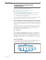
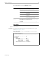
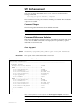
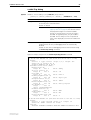
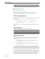
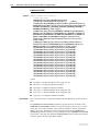
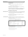
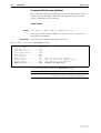
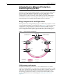
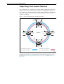
and managed using STP/RSTP. Figure 1-9 on page 1-13 shows a basic
combined EPSR / STP network.
Figure 1-9: EPSR and Spanning Tree Operation
Port 2
Secondary
Port 1
Primary
Other
Ports
l
tro
P
Co
ntr
ol
V
Node 1
N ta
LA Da
Master
Node
N
V LA
Dat
aV
LA Co
N n
S
AN
VL
Transit
Node
Other
Ports
Transit
Node
EPSR Ring
Other
Ports
Node 4
Node 2
Transit
Node
Port 1
Port 4
Da
ta
VL
AN
Node 3
STP/RSTP
Network
Data VLAN
Other
Ports
Port 2
Control VLAN (control_ring)
Port 3
AN
VL
ta
Da
Port 1
Port 2
Port 1
Other
Ports
Port 2
Data VLAN
EPSR 5.eps
Note that EPSR and STP cannot share the same ports.