1
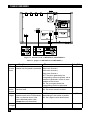
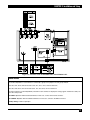
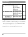
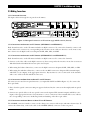
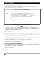
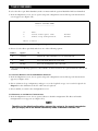
MARCH 2003
MT1000A-13
MT1000A-85
MT1000A-E1-13
MT1000A-E1-85
T1 and E1 Fiber Muxes
CUSTOMER
SUPPORT
INFORMATION
Order toll-free in the U.S.: Call 877-877-BBOX (outside U.S. call 724-746-5500)
FREE technical support 24 hours a day, 7 days a week: Call 724-746-5500 or fax 724-746-0746
Mailing address: Black Box Corporation, 1000 Park Drive, Lawrence, PA 15055-1018
Web site: www.blackbox.com • E-mail: [email protected]
FCC AND IC RFI STATEMENTS
FEDERAL COMMUNICATIONS COMMISSION
AND
INDUSTRY CANADA
RADIO FREQUENCY INTERFERENCE STATEMENTS
This equipment generates, uses, and can radiate radio-frequency energy, and if not installed and used
properly, that is, in strict accordance with the manufacturer’s instructions, may cause interference to radio
communication. It has been tested and found to comply with the limits for a Class A computing device in
accordance with the specifications in Subpart B of Part 15 of FCC rules, which are designed to provide
reasonable protection against such interference when the equipment is operated in a commercial
environment. Operation of this equipment in a residential area is likely to cause interference, in which
case the user at his own expense will be required to take whatever measures may be necessary to correct
the interference.
Changes or modifications not expressly approved by the party responsible for compliance could void the user’s
authority to operate the equipment.
This digital apparatus does not exceed the Class A limits for radio noise emission from digital apparatus set out in the Radio
Interference Regulation of Industry Canada.
Le présent appareil numérique n’émet pas de bruits radioélectriques dépassant les limites applicables aux appareils numériques
de la classe A prescrites dans le Règlement sur le brouillage radioélectrique publié par Industrie Canada.
1
T1 AND E1 FIBER MUXES
INSTRUCCIONES DE SEGURIDAD (Normas Oficiales Mexicanas Electrical Safety Statement)
1. Todas las instrucciones de seguridad y operación deberán ser leídas antes de que el aparato eléctrico sea operado.
2. Las instrucciones de seguridad y operación deberán ser guardadas para referencia futura.
3. Todas las advertencias en el aparato eléctrico y en sus instrucciones de operación deben ser respetadas.
4. Todas las instrucciones de operación y uso deben ser seguidas.
5. El aparato eléctrico no deberá ser usado cerca del agua—por ejemplo, cerca de la tina de baño, lavabo, sótano
mojado o cerca de una alberca, etc..
6. El aparato eléctrico debe ser usado únicamente con carritos o pedestales que sean recomendados por el fabricante.
7. El aparato eléctrico debe ser montado a la pared o al techo sólo como sea recomendado por el fabricante.
8. Servicio—El usuario no debe intentar dar servicio al equipo eléctrico más allá a lo descrito en las instrucciones de
operación. Todo otro servicio deberá ser referido a personal de servicio calificado.
9. El aparato eléctrico debe ser situado de tal manera que su posición no interfiera su uso. La colocación del aparato
eléctrico sobre una cama, sofá, alfombra o superficie similar puede bloquea la ventilación, no se debe colocar en
libreros o gabinetes que impidan el flujo de aire por los orificios de ventilación.
10. El equipo eléctrico deber ser situado fuera del alcance de fuentes de calor como radiadores, registros de calor, estufas
u otros aparatos (incluyendo amplificadores) que producen calor.
11. El aparato eléctrico deberá ser connectado a una fuente de poder sólo del tipo descrito en el instructivo de
operación, o como se indique en el aparato.
12. Precaución debe ser tomada de tal manera que la tierra fisica y la polarización del equipo no sea eliminada.
13. Los cables de la fuente de poder deben ser guiados de tal manera que no sean pisados ni pellizcados por objetos
colocados sobre o contra ellos, poniendo particular atención a los contactos y receptáculos donde salen del aparato.
14. El equipo eléctrico debe ser limpiado únicamente de acuerdo a las recomendaciones del fabricante.
15. En caso de existir, una antena externa deberá ser localizada lejos de las lineas de energia.
16. El cable de corriente deberá ser desconectado del cuando el equipo no sea usado por un largo periodo de tiempo.
17. Cuidado debe ser tomado de tal manera que objectos liquidos no sean derramados sobre la cubierta u orificios de
ventilación.
18. Servicio por personal calificado deberá ser provisto cuando:
A: El cable de poder o el contacto ha sido dañado; u
B: Objectos han caído o líquido ha sido derramado dentro del aparato; o
C: El aparato ha sido expuesto a la lluvia; o
D: El aparato parece no operar normalmente o muestra un cambio en su desempeño; o
E: El aparato ha sido tirado o su cubierta ha sido dañada.
2
TRADEMARKS/WARNINGS
TRADEMARKS USED IN THIS MANUAL
ST is a registered trademark of AT&T.
Any other trademarks mentioned in this manual are acknowledged to be the property of the trademark owners.
WARNING
These products are equipped with a laser diode. Please observe the following
precautions:
• Before turning on the equipment, make sure that the fiber optic cable is intact and is
connected to the transmitter.
• Do not attempt to adjust the laser drive current.
• Do not use broken or unterminated fiber optic cables/connectors or look straight at
the laser beam.
• Using optical devices with this equipment will increase the risk of eye injury.
• Performing procedures other than those specified herein may result in hazardous
radiation exposure.
CAUTION: The laser beam may be invisible!
Always observe standard safety precautions during product installation, operation,
and maintenance. Only qualified and authorized service personnel should carry out
product adjustment, maintenance, or repairs. No installation, adjustment,
maintenance, or repairs should be performed by either the operator or the user.
3
T1 AND E1 FIBER MUXES
Contents
Chapter
Page
1. Specifications ............................................................................................................................................................6
2. Introduction..............................................................................................................................................................8
2.1 Overview ...........................................................................................................................................................8
2.2 Physical Description ........................................................................................................................................9
2.3 Functional Description....................................................................................................................................9
2.3.1 Fiber Link Interface Characteristics ..................................................................................................9
2.3.2 Channel Interface Characteristics ...................................................................................................10
2.3.3 Service Channel.................................................................................................................................10
2.3.4 Test and Diagnostic Capabilities ......................................................................................................11
2.3.5 Management and Monitoring..........................................................................................................12
2.3.6 Power Requirements .........................................................................................................................12
2.4 Package Contents ..........................................................................................................................................12
3. Installation and Setup ............................................................................................................................................13
3.1 Introduction...................................................................................................................................................13
3.2 Site Requirements and Prerequisites ...........................................................................................................13
3.2.1 Power..................................................................................................................................................13
3.2.2 Channel Connections .......................................................................................................................13
3.2.3 Fiber Link Connections ....................................................................................................................13
3.2.4 Front and Rear Clearance ................................................................................................................14
3.2.5 Ambient Requirements.....................................................................................................................14
3.3 Additional Equipment Needed ....................................................................................................................14
3.4 Setting the Internal Jumpers and Switches..................................................................................................14
3.5 Making Connections .....................................................................................................................................19
3.5.1 Connector Location..........................................................................................................................19
3.5.2 Connecting the Channels on T1 Versions (MT1000A-85 and MT1000A-13) ..............................19
3.5.3 Connecting the Channels on E1 Versions (MT1000A-E1-85 and MT1000A-E1-13)....................19
3.5.4 Connecting the Fiber Links on Both T1 and E1 Versions .............................................................19
3.5.5 Connecting the Alarm Relays on Both T1 and E1 Versions ..........................................................19
3.5.6 Connecting the Service Channel on Both T1 and E1 Versions.....................................................20
3.5.7 Grounding .........................................................................................................................................20
3.5.8 Connecting the AC Power ................................................................................................................20
3.6 Rackmounting the Mux ................................................................................................................................20
4. Operation ................................................................................................................................................................21
4.1 Front-Panel Indicators, Connectors, and Pushbutton ................................................................................21
4.2 Operating Instructions..................................................................................................................................23
4.2.1 Turning the Mux On............................................................................................................................23
4.2.2 Normal Indications ..............................................................................................................................23
4.2.3 Using the Service Channel ..................................................................................................................23
4.2.4 Turning the Mux Off ...........................................................................................................................23
4
CONTENTS
Chapter
Page
5. Management ...........................................................................................................................................................24
5.1 Setting Terminal Communication................................................................................................................24
5.1.1 Setting the Terminal Communication Parameters.........................................................................24
5.1.2 Entering the Terminal Session .........................................................................................................25
5.2 Status Monitoring ..........................................................................................................................................26
5.2.1 T1 or E1 and Fiber Optic Interface Status ......................................................................................26
5.2.2 Functional Blocks Status ...................................................................................................................27
5.3 Configuring the Mux.....................................................................................................................................28
5.3.1 Viewing the Interface Configurations .............................................................................................28
5.3.2 Setting/Resetting Loopbacks in the Local Mux .............................................................................30
5.3.3 Setting/Resetting Loopbacks in the Remote Mux .........................................................................30
5.3.4 Invoking Special Actions...................................................................................................................31
5.3.5 Setting/Resetting the T1 or E1 Remote Loopback........................................................................32
5.3.6 Resetting to the Default Configuration ...........................................................................................32
5.4 Changing the Password .................................................................................................................................33
5.5 Viewing Hardware and Software Updates ...................................................................................................34
5.6 Downloading Software ..................................................................................................................................34
6. Testing and Diagnostics..........................................................................................................................................35
6.1 Diagnostic Tests..............................................................................................................................................35
6.1.1 Local Loopbacks in the Local Mux..................................................................................................35
6.1.2 Local Loopbacks in the Remote Mux..............................................................................................37
6.1.3 Fiber Optic Remote Loopback.........................................................................................................38
6.2 Troubleshooting ............................................................................................................................................39
6.3 Calling Black Box ..........................................................................................................................................40
6.4 Shipping and Packaging ...............................................................................................................................40
Appendix. Interface Specifications............................................................................................................................41
A.1 Channel Connectors .....................................................................................................................................41
A.2 ALARMS Connector......................................................................................................................................41
A.3 CONTROL Connector..................................................................................................................................42
A.4 Power Connectors..........................................................................................................................................42
5
T1 AND E1 FIBER MUXES
1. Specifications
Fiber Optic Interface (All Models)
Standards — ITU-T Rec. G.956
Data Rates — MT1000A-85 and MT1000A-13: 6.176 Mbps, nominal;
MT1000A-E1-85 and MT1000A-E1-13: 8.448 Mbps (E2 link), nominal
Maximum Distance — MT1000A-85: Multimode up to 3 km (1.9 miles);
MT1000A-13: Single-mode up to 48 km (29.8 miles);
MT1000A-E1-85: Multimode up to 4 km (2.5 miles);
MT1000A-E1-13: Single-mode up to 44 km (27.3)
Performance — See Table 2-1
Connectors — (1) pair ST®
Supervisor Port Specifications (All Models)
Control DTE Interface — V.24/RS-232, asynchronous
Control DTE Connectors — (1) DB9 F
Control DTE Data Rates — 9.6, 19.2, 38.4, or 57.6 kbps
Voice Service Channel for Standard Headset (All Models)
Input Impedance — 33 kΩ
Input Level — 5 mV
Output Level — 50 mW @ 8Ω
Bandwidth (-3 dB) — 3 to 3000 Hz
Call Indication — LED and internal buzzer
ALARMS Relay Connector (All Models)
Connector — (1) DB9 F
Contact Functions — Set of floating normally closed/normally open contacts for major and minor alarm
indication
Contact Rating (Maximum) — 1 A (at 60 VDC or 30 VAC) through closed contacts
6
CHAPTER 1: Specifications
T1 Channel Interfaces (MT1000A-85 and MT1000A-13)
Standards — ITU-T Rec. G.703, G.824
Line Data Rate — 1.544 Mbps, nominal
Line Encoding — B8ZS
Line Impedance — 100 Ω balanced
Transmit Levels — ±2.8V ± 10%
Receive Levels — 0 dB to -2.4 dB
Jitter Performance — Per ITU-T Rec. G.824, Para. 4
Connectors — (4) RJ-48C
E1 Channel Interfaces (MT1000A-E1-85 and MT1000A-E1-13)
Standards — ITU-T Rec. G.703, G.823
Line Data Rate — 2.048 Mbps, nominal
Line Encoding — HDB3
Line Impedance — 120 Ω balanced; 75 Ω unbalanced
Unbalanced Interface — ±2.37V ± 10%
Receive Levels — 0 to -6 dB
Jitter Performance — Per ITU-T Rec. G.823
Connectors — Balanced interface: (4) RJ-45; Unbalanced interface: (2) BNC coax per channel
General Specifications (All Models)
Indicators — (20) LEDs: POWER A, POWER B, SYSTEM MNG, SYSTEM CALL, LOC TEST, REM TEST, MAIN,
BACKUP, AIS MAIN, AIS BACKUP, SYNC LOSS MAIN, SYNC LOSS BACKUP, AIS CH1, AIS CH2, AIS CH3,
AIS CH4, SYNC LOSS CH1, SYNC LOSS CH2, SYNC LOSS CH3, SYNC LOSS CH4
Temperature — Operating: 32 to 122°F (0 to 50°C)
Relative Humidity — Up to 90%, noncondensing
Power — (2) 100–240-VAC, 47–63-Hz, autosensing, 12-VA power supplies
Size — 1.75"H (1U) x 17"W x 8.2"D (4.4 x 43.2 x 20.8 cm)
Weight — 4.4 lb. (2 kg)
7
T1 AND E1 FIBER MUXES
2. Introduction
2.1 Overview
The T1 and E1 Fiber Muxes (available in 850-nm and 1310-nm versions) combine four T1(1.544 Mbps) or E1
(2.048 Mbps) channels into a single fiber optic link that boasts data rates of either 6.176 Mbps (T1 versions)
or 8.448 Mbps (E1 versions). On the fiber optic side, the multiplexor’s interface gives you a secure link that
communicates in areas susceptible to electromagnetic interference while increasing the maximum connection
range. The fiber interface also protects against the harmful effects of ground loops. The muxes can only be
used in pairs.
The T1 and E1 Fiber Muxes offer these additional features:
• A pair of the 850-nm T1 muxes offers multimode distances of up to 3 km (1.9 miles), and a pair of the
single-mode 1310-nm T1 muxes gives you a maximum range of 48 km (29.8 miles).
• Used in pairs, the E1 muxes offer multimode distances of 4 km (2.5 miles) with the 850-nm model and
single-mode distances of 44 km (27.3) with the 1310-nm model.
• Redundant power supply for all versions.
• Voice service channel for end-to-end communications between maintenance personnel.
• Transmits each of the T1 or E1 channels independently, so each channel can have its own clock source.
• T1 models conform to ITU G.956, G.703, and G.824 standards. E1 models meet ITU G.956, G.703, and
G.823 standards.
T1 or E1 Channel Links
to Various Devices
Fiber Link
Voice
Channel
Connection
ASCII Terminal Linked
to Supervisory Port
(Optional) Backup Fiber Link
Voice
Channel
Connection
ASCII Terminal Linked
to Supervisory Port
Figure 2-1. Typical application showing a pair of local and remote T1 or E1 Fiber Muxes.
(Note that the backup fiber link is possible only by adding an optional redundant fiber link board to each mux.
For more information on this modular board, contact Technical Support.)
8
CHAPTER 2: Introduction
MODELS AVAILABLE:
• T1 Fiber Mux 850-nm (MT1000A-85)
• T1 Fiber Mux 1300-nm (MT1000A-13)
• E1 Fiber Mux 850-nm (MT1000A-E1-85)
• E1 Fiber Mux 1300-nm (MT1000A-E1-13)
2.2 Physical Description
The T1 or E1 Fiber Mux is a compact unit that’s only 1U (1.75") high, so installation on a desktop or shelf is
easy. We also offer a Rackmount Kit (RM1001), which enables you to install the mux in a 19" rack.
The mux’s front panel provides LED indicators, a control connector, and a headset jack, as illustrated in
Figure 2-2. For more information about the front-panel indicators and connectors, refer to Chapter 4. Power
connectors, fiber optic connectors, and T1 or E1 interfaces can be accessed via the mux’s rear panel. For more
information about rear-panel connectors, refer to Section 3.5.
Figure 2-2. The mux’s front-panel indicators and connectors.
2.3 Functional Description
T1 and E1 Fiber Muxes contain a main circuit board, including four channel interfaces, and one fiber optic
interface board. The interfaces are described below along with descriptions of the service channel, test and
diagnostic capabilities, management and monitoring, and power requirements. An optional redundant fiber
link board for establishing a backup fiber link is also available, as is a redundant E2 link board and DC powersupply options. (For more information, contact Technical Support.)
2.3.1 FIBER LINK INTERFACE CHARACTERISTICS
The installed fiber optic interface, which has a pair of ST connectors, complies with the requirements of
ITU-T Rec. G.956, and uses a proprietary signaling format that ensures optimum performance. To optimally
meet a wide range of system requirements, the fiber interface on the MT1000A-85 and MT1000A-E1-85 enables
operation over 62.5/125-micron multimode fibers (typical attenuation -3.5 dB/km) and features a Vertical
Cavity Surface Emitting Laser (VCSEL) type of transmitter. The interface on the MT1000A-13 and MT1000AE1-13 offers operation over low-loss 9/125-micron single-mode fibers (typical attenuation -0.4 dB/km at 1300
nm, and 0.25 dB/km at 1550 nm) and features a laser transmitter.
Table 2-1 lists the optical sub system’s characteristics including the maximum range over typical fiber optic
cable. The maximum range values given in the table assume a 3 dB margin.
9
T1 AND E1 FIBER MUXES
Table 2-1. Fiber optic characteristics.
Model (Wavelength)
Fiber Type
Transmitter Typical Output Receiver
Typical
Type
Power
Sensitivity Maximum
Range
T1 Versions
MT1000A-85 (850 nm)
MT1000A-13 (1310 nm)
62.5/125 multimode
9/125 single-mode
VCSEL
Laser
-18 dBm
-12 dBm
-32 dBm
-34 dBm
3 km (1.9 miles)
48 km (29.8 miles)
E1 Versions
MT1000A-E1-85 (850 nm) 62.5/125 multimode
MT1000A-E1-13 (1310 nm) 9/125 single-mode
VCSEL
Laser
-18 dBm
-12 dBm
-32 dBm
-34 dBm
4 km (2.5 miles)
44 km (27.3 miles)
All fiber interfaces offer high performance and have a wide dynamic range, which ensures that the receiver
does not saturate even when using short fiber optic cables. (Saturation is caused when the optical power
applied to the receiver exceeds its maximum allowed input power and results in very high bit error rates.)
2.3.2 CHANNEL INTERFACE CHARACTERISTICS
T1 channel interfaces
The T1 muxes’ channel interfaces meet the requirements of ITU-T Rec. G.703. Each channel port on the T1
models has a 100-ohm (Ω) balanced line interface terminated in an RJ-45 eight-pin connector. Line coding is
B8ZS. The nominal balanced interface transmit level is ±2.8 V. The line attenuation is up to 6 dB, and each
T1 signal is processed by an adaptive equalizer that compensates for various cable lengths to ensure optimal
performance. The T1 muxes use phase locked loops (PLL) to recover the clock signals, and the resulting jitter
performance complies with the requirements of ITU-T Rec. G.824, Para. 4.
E1 channel interfaces
As with the T1 models, the channel interfaces on the E1 Fiber Muxes meet the requirements of ITU-T Rec.
G.703. Each channel port on the E1 models has two line interfaces: a 120-ohm (Ω) balanced line interface,
terminated in an RJ-45 eight-pin connector, and a 75-ohm unbalanced interface, terminated in two BNC
coaxial connectors. Line coding is HDB3. The nominal balanced interface transmit level is ±3 V, and the
unbalanced interface transmit level is ±2.37 V. The maximum line attenuation is up to 6 dB, and each E1 signal
is processed by an adaptive equalizer that ensures optimal performance by compensating for various cable
lengths. Phase locked loops (PLL) are used to recover the clock signals, and the resulting jitter performance
complies with the requirements of ITU-T Rec. G.823.
Indicators common to both T1 and E1 versions
Each channel interface also has its own set of indicators that show the current state of the channel link. You can
use internal jumpers and switches to disable the alarm indications generated by unused interfaces. AIS data
streams are transmitted instead of failed or unconnected channel data streams.
2.3.3 SERVICE CHANNEL
The T1 or E1 Fiber Mux provides a full-duplex voice service channel. Operators of two units connected in a
link can communicate over this channel using standard headsets, which connect to sockets on the front panel.
When the local operator wants to speak to the remote operator, a CALL button is used. While this button is
pressed, a CALL indicator lights and an internal buzzer sounds on the remote unit. The proprietary
modulation method used for the service channel doesn’t affect range, and it enables the service channel to
operate independently of payload traffic (as long as the optical signal can be received at the remote end). This
way, operators at both ends can coordinate maintenance activities.
10
CHAPTER 2: Introduction
2.3.4 TEST AND DIAGNOSTIC CAPABILITIES
Each mux comes with comprehensive test and diagnostics capabilities, including local loopback on the fiber
link interface and remote loopbacks on each channel link. The remote loopbacks are activated on the remote
units. To perform activation, send a special test sequence through the fiber link. An automatic self-test on
power-up further enhances maintenance. For activation of the above and other loopbacks, see Chapter 6.
Alarms and alarm indications
The muxes can detect the following alarm conditions on each T1 or E1 and fiber interface:
• Loss of input signal.
• Loss of frame synchronization.
• Reception of alarm indication (AIS) signal, which consists of a continuous sequence of ones (“1”s).
NOTE
When AIS is received, loss of frame synchronization occurs. However, in this case, the
alarm indicating loss of frame synchronization is suppressed.
If the user isn’t using all of the channels, the user can disable the alarm indications related to the unused
channels. The response to alarm conditions is as follows:
• The detection of loss of fiber input signal, the reception of AIS on the fiber input, or loss of fiber frame
synchronization result in the transmission of AIS on each channel output.
• For each channel, an AIS signal is sent instead of the channel data stream through the fiber link upon
detection of loss of channel input signal, the reception of AIS on the channel input, or loss of channel
frame synchronization.
Front-panel indicators display each alarm condition. The mux also uses a dedicated connector to provide major
and minor alarm indications by means of dry contacts. The major alarm is activated in the following cases:
• The mux isn’t powered or there’s a total power-supply failure on either the primary or backup power
supply.
• There’s a loss of fiber optic input signals or loss of fiber optic frame synchronization.
• There’s a loss of channel input signals or loss of frame synchronization.
The minor alarm is activated in the following cases:
• There’s reception of AIS signal on the fiber optic input.
• There’s reception of AIS signal on channel inputs.
11
T1 AND E1 FIBER MUXES
2.3.5 MANAGEMENT AND MONITORING
The muxes are equipped with a front-panel RS-232 serial management port (“CONTROL”). This port operates
at user-selectable rates of 9.6, 19.2, and 38.4 kbps over a crossover cable (included). At the current time, the
management interface supports a single management method: via a supervision terminal. This can be an ASCII
terminal connected to the RS-232 port (or a PC running a terminal emulation program). The mux contains all
the software you need for performing the various management functions available through the terminal.
You will see SNMP management listed in the software’s main menu. However, the parameters for setting up an
SNMP-based system are reserved for future use.
2.3.6 POWER REQUIREMENTS
The T1 or E1 Fiber Mux includes two power supplies for redundancy. Each power supply supports AC
operation (100–240 VAC, 47–63 Hz), with each sharing the load; in case one of the supplies fails or its input
power is disconnected, the other power supply continues providing power to the mux. For DC power options,
call Technical Support.
2.4 Package Contents
Your mux package should contain the following items:
• T1 or E1 Fiber Mux.
• (1) DB9 male to DB9 female crossover cable.
• (2) Power-supply cables.
• Hands-free telephone headset.
• This users’ manual.
If anything is missing or damaged, please contact Black Box at 724-746-5500.
12
CHAPTER 3: Installation and Setup
3. Installation and Setup
3.1 Introduction
The T1 and E1 Fiber Muxes, shipped completely assembled, can be installed as desktop units or mounted in
19" racks with the optional Rackmount Kit (RM1001).
This chapter provides mechanical and electrical installation procedures for muxes, including the setting of the
internal jumpers and connecting the mux’s various interfaces.
After installing the mux, please refer to Chapter 4 for operating instructions and to Chapter 5 for systemconfiguration procedures.
If you encounter a problem, please refer to Chapter 6 for testing and diagnostics instructions.
WARNING
• No internal settings, adjustment, maintenance, or repairs may be performed by either
the operator or the user; such activities may be performed only by a skilled
technician who is aware of the hazards involved.
• Always observe standard safety precautions during product installation, operation,
and maintenance.
3.2 Site Requirements and Prerequisites
3.2.1 POWER
The mux should be installed within 5 feet (1.5 m) of an easily accessible grounded AC outlet capable of
furnishing a supply voltage in the range of 100 to 240 VAC.
3.2.2 CHANNEL CONNECTIONS
On T1 Fiber Muxes
Each T1 Fiber Mux channel interface has one RJ-45 connector. Only one interface can be in use at any time.
The Appendix provides the pin allocation for the RJ-45 connector. The maximum allowable line attenuation
between each channel port and the user’s equipment is 2.4 dB.
On E1 Fiber Muxes
Each E1 Fiber Mux channel interface has one RJ-45 connector (for the balanced link interface) and two BNC
connectors (for the unbalanced interface). Only one interface can be in use at any time. The Appendix
provides the pin allocation for the RJ-45 connector. The maximum allowable line attenuation between each
channel port and the user’s equipment is 6 dB.
3.2.3 FIBER LINK CONNECTIONS
Each fiber optic link interface is terminated in two ST connectors. See Table 2-1 for the maximum allowable
attenuation and other fiber optic interface characteristics.
13
T1 AND E1 FIBER MUXES
3.2.4 FRONT AND REAR CLEARANCE
Allow at least 36 inches (91.4 cm) of frontal clearance for operator access. Also allow at least 4 inches (10.2 cm)
clearance at the rear of the mux for your interface cable connections. When planning the routing of fiber optic
cables, avoid sharp bends.
3.2.5 AMBIENT REQUIREMENTS
The mux’s ambient operating temperature is 32 to 122°F (0 to 50°C), at a relative humidity of up to 90%,
noncondensing.
3.3 Additional Equipment Needed
You’ll need the following equipment (not included) to install the T1 or E1 Fiber Mux:
• ST link connector cables (for optical interface).
• RJ-45 T1 or E1 connector cables (for channel interfaces).
If you plan on installing the mux in a 19" rack with the optional rackmount kit, you’ll also need a Phillips
screwdriver.
3.4 Setting the Internal Jumpers and Switches
WARNING
This product includes Class A or Class 1 lasers. For your safety:
• Do not look directly into the optical connectors while the multiplexor is operating.
Remember that the T1 or E1 Fiber Mux starts operating as soon as the Power button
is switched to On.
• Do not attempt to adjust the laser drive current.
• Using optical instruments with this equipment will increase the risk of eye injury.
Laser power up to 1 mW at 1310 nm and 1550 nm could be collected by an optical
instrument.
• Performing procedures other than those specified herein may result in hazardous
radiation exposure.
• CAUTION: The laser beam may be invisible.
Prior to installing the mux, check the positions of its internal jumpers and switches. If necessary, change the
settings in accordance with the specific requirements of your application.
To open the mux and access the internal jumpers and switches:
1. Disconnect all cables connected to the mux.
2. Unscrew the two large captive screws fastening the top cover to the rear panel.
3. Remove the mux’s top cover.
14
CHAPTER 3: Installation and Setup
WARNING
• Only qualified and authorized service personnel should access the inside of the
equipment. To avoid accidental electric shock, always disconnect the mux from the
power line and from all the cables before removing the cover.
• Dangerous high voltages are present inside the mux when it is connected to power
and/or to the links. Moreover, under external fault conditions, dangerous high voltages
may appear on the lines connected to the mux.
• Any adjustment, maintenance, and repair of the opened instrument under voltage
should be avoided as much as possible and, when inevitable, should be carried out
only by a skilled technician who is aware of the hazard involved.
• Capacitors inside the instrument may still be charged even after the instrument has
been disconnected from its source of supply.
CAUTION
The mux contains components sensitive to electrostatic discharge (ESD). To prevent
ESD damage, avoid touching the internal components, and before moving jumpers,
touch the mux’s frame to ground yourself.
The internal jumpers located on the mux’s main and interface boards are identified in Figures 3-1 and 3.2. The
functions of the jumpers are described in Tables 3-1 and 3-2.
To set the jumpers and switches:
1. Identify the jumper and switch locations. (Refer to Figure 3-1 or 3-2.)
2. Change the settings as required. (Refer to Tables 3-1 or 3-2 for setting options.)
CAUTION
Additional jumpers that are not listed in Figures 3-1 or 3-2 and Tables 3-1 or 3-2 exist.
They are set by the manufacturer and should not be touched!
15
T1 AND E1 FIBER MUXES
Figure 3-1. Internal boards on MT1000A-85 and MT1000A-13.
Table 3-1. Jumpers on MT1000A-85 and MT1000A-13.
Jumper
Description
JP23
Channel
Alarms
Controls the operation of the alarms,
whether they are ignored or processed.
JP26
Service
Channel
SW1-1
V-Agent
Controls the operation of the voice
service channel.
Controls the downloading of an
updated version of the FLASH memory
when a malfunction occurs in the
normal download process. (See
Chapter 5 for more information.)
SW1-2, 3, Not in use.
4 V-Agent
16
Values
JP23-1 sets Channel 1;
JP23-2 sets Channel 2;
JP23-3 sets Channel 3;
JP23-4 sets Channel 4.
OFF: The alarms generated by the
corresponding channel are ignored, and no
indication is generated in case of an alarm
condition on that channel.
ON: The alarms generated by the
corresponding channel are processed.
OFF: The service channel is disabled.
ON: The service channel is enabled.
Factory Setting
ON
ON
OFF: The V-Agent is set to FLASH and
downloading of a new version is possible.
ON: The V-Agent is set to default version.
OFF
Not in use.
—
CHAPTER 3: Installation and Setup
Figure 3-2. Internal boards on MT1000A-85-E1 and MT1000A-13-E1.
Channel Interface
The nominal impedance of each interface is selected by a group of five jumpers. The four groups include:
JP4, JP8, JP12, JP16, JP20 for Channel 1;JP3, JP7, JP11, JP15, JP19 for Channel 2;
JP2, JP6, JP10, JP14, JP18 for Channel 3;JP1, JP5, JP9, JP13, JP17 for Channel 4.
The type of interface can be independently selected for each channel, but all jumpers serving a given channel must always be
set to the same position.
120 Ω BAL: Operation with the balanced interface. In this case, connect to the RJ-45 connector.
75 Ω UNBAL: Operation with the unbalanced interface. In this case, connect to the BNC connectors.
Factory setting: 120 Ω for all jumpers.
17
T1 AND E1 FIBER MUXES
Table 3-2. Jumpers on MT1000A-85-E1 and MT1000A-13-E1.
Jumper
Description
JP23
Channel
Alarms
Controls the operation of the alarms,
whether they are ignored or processed.
JP26
Service
Channel
Controls the operation of the voice
service channel.
SW1-1
V-Agent
Controls the downloading of an
updated version of the FLASH memory
when a malfunction occurs in the
normal download process. (See
Chapter 5 for more information.)
SW1-2, 3, Not in use.
4 V-Agent
Values
JP23-1 sets Channel 1;
JP23-2 sets Channel 2;
JP23-3 sets Channel 3;
JP23-4 sets Channel 4.
OFF: The alarms generated by the
corresponding channel are ignored, and no
indication is generated in case of an alarm
condition on that channel.
ON: The alarms generated by the
corresponding channel are processed.
OFF: The service channel is disabled.
Always use this setting when an optional
electrical E2 interface is installed.
ON: The service channel is enabled. This is
the factory-default setting when the fiber
optic interface is installed.
OFF: The V-Agent is set to FLASH and
downloading of a new version is possible.
ON: The V-Agent is set to default version.
Not in use.
Factory Setting
ON
ON
OFF
—
After completing the internal settings, replace the mux’s cover. To do this:
1. Position the lower half of the mux’s case on a flat, clean surface. Check that the decorative black plastic strips
on the sides of the unit are still in place. (If not, place the strips in the grooves on the sides of the lower half.)
2. Identify the cover’s front and rear, and position the cover on the lower half of the mux so that the cover
guides are located just above the holes in the lower half. Close the cover and ensure that the protruding tips
of the cover guides enter the corresponding recesses in the lower half.
3. Hold the cover in place and turn the assembled mux over to gain access to the bottom half of the unit.
4. Insert the original cover screws in their positions and tighten carefully. Do not use excessive force!
18
CHAPTER 3: Installation and Setup
3.5 Making Connections
3.5.1 CONNECTOR LOCATION
The figures below show typical rear panels on the muxes.
Figure 3-3. Rear-panel connectors on T1 versions (top) and E1 versions (bottom).
3.5.2 CONNECTING THE CHANNELS ON T1 VERSIONS (MT1000A-85 AND MT1000A-13)
Each channel interface on the T1 muxes includes one RJ-45 connector. To connect the channels, connect each
of the cables to the connector(s) corresponding to the interface in use. Only one interface can be in use at any
time. Connect to the RJ-45 connectors designated CH1, CH2, CH3, and CH4.
3.5.3 CONNECTING THE CHANNELS ON E1 VERSIONS (MT1000A-E1-85 AND MT1000A-E1-13)
Each channel interface on the E1 muxes includes one RJ-45 connector. To connect the channels:
1. Connect each of the cables to the RJ-45 connector(s) that correspond to the interface in use. Do not connect to
both the balanced and unbalanced connectors of the same interface!
2. When using the balanced interfaces, connect to the RJ-45 connectors designated CH1, CH2, CH3, or CH4.
3. When using the unbalanced interface, connect to the two BNC connectors designated IN (transmit input)
and OUT (receive output) of the appropriate interface. Pay attention to correct connection of the transmit
and receive cables to the IN and OUT connectors.
3.5.4 CONNECTING THE FIBER LINKS ON BOTH T1 AND E1 VERSIONS
ST connectors are used for an optical interface (see inputs labeled TX and RX in Figure 3-3). To connect the
fiber optic links:
1. First, clean the optical connectors using an approved solvent. Dry the connectors thoroughly with an optical
tissue.
2. Connect two optical cables to the two optical connectors designated TX (transmit output) and RX (receive
input) of the appropriate interface. Pay attention to correct connection of the transmit and receive cables to
the corresponding connectors. Avoid sharp bends and twisting of the fiber optic cables.
3.5.5 CONNECTING THE ALARM RELAYS ON BOTH T1 AND E1 VERSIONS
The ALARMS connector is used to connect to the changeover contacts of the major and minor alarm relays. To
connect the alarm relays, connect the cable to the ALARMS (DB9 F) connector on the rear panel.
19
T1 AND E1 FIBER MUXES
3.5.6 CONNECTING THE SERVICE CHANNEL ON BOTH T1 AND E1 VERSIONS
To connect the service channel, connect the headset to the service channel socket located in the SYSTEM
section of the front panel.
3.5.7 GROUNDING
The connection of the protective ground is accomplished through one of the pins of the power connector.
WARNING
• This instrument may become dangerous if damage to the protective (grounding)
conductor (inside or outside the instrument) occurs or if disconnecting from the
protective ground terminal.
• Before switching on this instrument and before connecting any other cable, the
protective ground terminals of this instrument must be connected to the protective
ground conductor of the power cords. The power plugs shall only be inserted in a
socket outlets provided with a protective ground contact. The protective action must
not be negated by use of an extension cord (power cable) without a protective
conductor (grounding).
• Make sure that only fuses with the required current rate, as marked on the mux’s rear
panel, are used for replacement. The use of repaired fuses and the short-circuiting of
fuse holders is forbidden. Whenever it is likely that the protection offered by fuses
has been impaired, the instrument must be made inoperative and should be secured
against any unintended operation.
3.5.8 CONNECTING THE AC POWER
Figure 3-3 shows the muxes’ rear-panel power connectors. Each mux has dual AC power supplies, with dual
power plug inputs and a power switch for each power supply.
AC power should be supplied to the mux through the included 5-foot (1.5-m) standard power cables
terminated by standard 3-prong plugs.
To connect the mux to AC power:
1. Make sure the corresponding ON/OFF switches on both of the mux’s rear power-supply panels are set to OFF.
2. Connect each power cable to the connectors on the mux’s rear panel.
3. Connect each power cable to the mains outlets.
3.6 Rackmounting the Mux
The optional Rackmount Kit (RM1001) includes two brackets and a set of screws for mounting the mux in a 19"
rack. The brackets affix to the sides of the mux and to the rack, with the brackets’ posts aligned with the
recessed holes on the sides of the mux.
20
CHAPTER 4: Operation
4. Operation
In this chapter, you’ll find detailed instructions for operating the T1 or E1 Fiber Mux. The information
presented in this chapter includes a description of the mux’s front-panel controls and its operating procedures
(turning on, front-panel indications, and turning off).
4.1 Front-Panel Indicators, Connectors, and Pushbutton
Figure 4-1 shows the mux’s front panel. Table 4-1 lists the functions of the mux’s connectors, indicators, and
single button located on the front panel. The numbers in Table 4-1 correspond to the numbers in Figure 4-1.
Figure 4-1. The mux’s front panel.
Table 4-1. Front-panel indicator, button, or connector and corresponding function.
Number Indicator/Button/Connector
Function
1
POWER A indicator
Off when the main power supply is not powered.
Lights in green when the main power supply is turned on and operates
normally.
Lights in red when the main power supply is turned on and a malfunction has
been detected. In this case, the mux continues to operate normally using the
backup power supply.
2
POWER B indicator
Off when the backup power supply is not powered.
Lights in green when the backup power supply is turned on and operates
normally.
Lights in red when the backup power supply is turned on and a malfunction
has been detected. In this case, the mux continues to operate normally using
the main power supply.
3
SYSTEM MNG indicator
Lights when the internal management board is engaged in an active
management session.
When the MNG indicator lights, the front-panel SYSTEM CALL pushbutton is
functional.
4
SYSTEM CALL indicator
Lights when a call alert is received through the service channel from the
remote operator.
21
T1 AND E1 FIBER MUXES
Table 4-1 (continued). Front-panel indicator, button, or connector and corresponding function.
Number Indicator/Button/Connector
Function
5
SYSTEM CALL pushbutton When the service channel is enabled, pressing this button sends an alert to the
remote operator to signal that the local operator wants to speak.
6
SYSTEM headset jack
Miniature jack for connection of headset to the service channel.
7
LOC TEST indicator
Lights when the local loopback is activated on the local mux.
8
REM TEST indicator
Lights when the remote loopback is activated on either the local or the remote
mux.
9
MAIN indicator
Lights when Force Main Link is activated.
Off in normal operation mode.
10
BACKUP indicator
Available only when the optional dual fiber link board is installed. Always off if
there is no optional board installed.
If the optional board is installed, indicator lights when Force Backup Link is
activated and is off in normal operation mode.
11
AIS MAIN indicator
Lights when the AIS signal is received on the main fiber optic link.
12
AIS BACKUP indicator
Available only when the optional dual fiber link board is installed. Always off if
there is no optional board installed.
If the optional board is installed, lights when the AIS signal is received on the
backup fiber optic link.
13
SYNC LOSS MAIN
indicator
Lights in case the main link bit error rate exceeds 10-6.
14
SYNC LOSS BACKUP
indicator
Available only when optional dual fiber link board is installed. Always off if there
is no optional board installed. If the optional board is installed, lights in case the
backup link bit error rate exceeds 10-6.
15
AIS CH1 indicator
Lights when an AIS signal is output by the corresponding channel interface.
16
AIS CH2 indicator
17
AIS CH3 indicator
18
AIS CH4 indicator
19
SYNC LOSS CH1 indicator Lights when the corresponding channel interface reports loss of input signal.
20
SYNC LOSS CH2 indicator
22
CHAPTER 4: Operation
Table 4-1 (continued). Front-panel indicator, button, or connector and corresponding function.
Number Indicator/Button/Connector
Function
21
SYNC LOSS CH3 indicator Lights when the corresponding channel interface reports loss of input signal.
22
SYNC LOSS CH4 indicator
23
CONTROL connector
Connection to the management interface.
4.2 Operating Instructions
4.2.1 TURNING THE MUX ON
To turn on the mux, set at least one of the two rear POWER switches to ON. (In general, you should turn on
both POWER switches in order to achieve power source redundancy.) The corresponding POWER indicator(s)
light in green.
4.2.2 NORMAL INDICATIONS
During normal operation:
• The POWER indicators of the active power supply sources light in green.
• The MAIN indicator lights on. However, if you are using the mux with the optional dual fiber link board
installed, the light corresponding to the fiber optic link in use (MAIN or BACKUP) lights up.
• All SYNC LOSS, AIS, and TEST front-panel indicators are off.
4.2.3 USING THE SERVICE CHANNEL
1. Plug a headset into the front-panel jack.
2. Press the CALL pushbutton and wait for the answer of the remote operator to start a conversation.
3. After the remote operator answers, you can speak freely, as the service channel operates full-duplex.
4. To answer an incoming call: When the buzzer sounds (the CALL front-panel indicator also lights while the
buzzer sounds), put on the headset and answer.
4.2.4 TURNING THE MUX OFF
To turn off the mux, set the rear power switches to OFF.
23
T1 AND E1 FIBER MUXES
5. Management
A terminal can be used for configuration, monitoring, and maintenance operations.
At this time, the T1 or E1 Fiber Mux provides one terminal management mode (Monitor mode) with a
supervisory ASCII ANSI terminal or a PC emulating an ASCII ANSI terminal connected directly to the mux’s
CONTROL port.
SLIP mode, which uses a multidrop connection to an SNMP management workstation, is reserved for future
use.
5.1 Setting Terminal Communication
5.1.1 SETTING THE TERMINAL COMMUNICATION PARAMETERS
1. Connect the terminal to the DB9 (DTE) CONTROL connector on the mux’s front panel using the included
cable. If a PC is used (instead of a dumb terminal), run a terminal emulation program.
2. In your terminal emulation program or dumb terminal, set the default parameters of the terminal
communication port to a baud rate of 19,200 bps, 8 bits per character, one stop bit, and no parity bit.
3. Reset the mux or turn it ON but be alert: When you see dots (...) crossing your screen, press <Enter> at least
four times and a press the dot key (.) The dots crossing the screen should last for a period of 5 seconds.
Pressing the dot key (.) once, as instructed above, sets the parity and complete terminal detection when a
correct baud rate is detected.
NOTE
The mux automatically detects and adapts itself to terminal baud rates of 9,600,
19,200, 38,400, and 57,600 bps. If the autodetection fails, the mux’s CONTROL port
uses the last baud rate written in the non-volatile RAM. Configuration of the baud rate
can be performed manually if you choose not to use the autodetection feature.
If autodetection of the baud rate occurs correctly, the opening screen should appear (see Figure 5-1). The mux
assumes Monitor mode when entering the terminal session.
For MONITOR mode enter <ENTER>monitor<ENTER>
Figure 5-1. Opening screen.
If, however, the terminal baud settings differ from the mux settings, the dots are received as indecipherable
data crossing the screen when you reset or turn ON the mux. If this occurs:
• Press <Enter> as the data crosses the screen. This should change the indecipherable data to dots (...).
• Then press the dot (.) key. The opening screen should appear (see Figure 5-1).
24
CHAPTER 5: Management
If the autodetection still fails, reset the terminal emulation program and try a baud rate that differs from the
one you used in step 2. Once you reset the baud rate, proceed to step 3 and begin the autodetection again. If
this fails, call Technical Support for assistance.
4. To enter the Monitor mode, press <Enter>, type monitor, and press <Enter> again.
5. At this point, you are prompted to enter the password. The default password for starting terminal operations
is “fibermux” (all eight characters are lower case).
5.1.2 ENTERING THE TERMINAL SESSION
When entering the terminal session for the first time, type the “fibermux” default password (an asterisk [*]
appears on the screen after each typed character) and press <Enter>. The Main Fibermux menu appears (see
Figure 5-2).
MAIN FIBERMUX MENU
----------------0.
1.
2.
3.
4.
5.
6.
Exit.
Status.
Configuration.
Password management.
Version information.
Software download.
SNMP parameters.
Enter a choice
:
Figure 5-2. Main Fibermux menu.
For the menu map, refer to Figure 5-3.
The options to change local and remote interface configurations under the Configuration option refer
to setting local loopback connections in both the local and remote T1 or E1 Fiber Muxes.
The Special Actions menu contains fiber optic link redundancy types (available only if you install the optional
redundant fiber link board on the motherboard) and the T1 or E1’s remote loopback setting.
SNMP Parameters is reserved for future use.
25
T1 AND E1 FIBER MUXES
Figure 5-3. Menu map.
5.2 Status Monitoring
You can monitor the transmission status at the T1 or E1 and fiber optic interfaces (Interface Status) and the
status of the mux’s functional blocks (Internal Status).
5.2.1 T1 OR E1 AND FIBER OPTIC INTERFACE STATUS
1. In the Main Fibermux menu (Figure 5-2), choose option 1, Status. The Status screen appears (Figure 5-4).
STATUS
-----0.
1.
2.
Exit.
Interface status.
Internal status.
Enter a choice:
Figure 5-4. Status screen.
26
CHAPTER 5: Management
2. Choose option 1, Interface status. The Interface Status screen appears, displaying one of the following states
for each T1 or E1 and fiber optic interface in the local and remote muxes (see Figure 5-5):
• Data signal
The input signal is detected on the respective line.
• Signal loss
A loss of input signal on the respective line.
• AIS
An Alarm Indication Signal (“all ones”) is detected on the respective line.
INTERFACE STATUS
--------------------------------------------------------------------------------|
Input to interface
|
Local
|
Remote
-----------------------------------------------------------------|
T1 channel 1
|
Signal loss
|
Signal loss
|
T1 channel 2
|
Signal loss
|
Signal loss
|
T1 channel 3
|
Signal loss
|
Signal loss
|
T1 channel 4
|
Signal loss
|
Signal loss
|
T2 main
|
Signal loss
|
Signal loss
|
T2 backup
|
Not present
|
Not present
-----------------------------------------------------------------0.Exit.
|
|
|
|
|
|
|
Figure 5-5. Interface Status screen.
NOTE
On E1 versions, T1 or T2 entries are replaced by E1 or E2, and status monitoring for
the T2 backup (or E2 backup on E2 versions) is only available if you add the optional
dual fiber link board to the mux.
3. Select 0, Exit, to return to the Status screen.
5.2.2 FUNCTIONAL BLOCKS STATUS
To monitor the status of the mux’s functional blocks (see Table 5-1):
1. In the Status screen, choose option 2, Internal status. The Internal Status screen appears, displaying one of
the following states for each functional block in both the local and remote muxes (see Figure 5-6).
2. Select 0, Exit, to return to the Status screen.
Table 5-1. Functional blocks status.
Block
Elastic store
Demultiplexor
Power supply
State
Valid
Not valid
Valid
Not valid
Valid
Not valid
Not present
Indicates
Block is functioning properly.
Block failure or incorrect channel frequency.
Block is functioning properly.
Block failure or loss of T1 or E1 frame.
Block is functioning properly.
No output voltages are supplied.
Power supply is not installed.
27
T1 AND E1 FIBER MUXES
INTERNAL STATUS
----------------
|
|
|
|
|
|
|
|
----------------------------------------------------------------Element
|
Local
|
Remote
----------------------------------------------------------------Elastic store T1 channel 1
|
Valid
|
Valid
Elastic store T1 channel 2
|
Valid
|
Valid
Elastic store T1 channel 3
|
Valid
|
Valid
Elastic store T1 channel 4
|
Valid
|
Valid
Demultiplexer
|
Valid
|
Valid
Power supply 1
|
Valid
|
Valid
Power supply 2
|
Valid
|
Valid
-----------------------------------------------------------------
|
|
|
|
|
|
|
|
0.Exit.
Figure 5-6. Internal Status screen.
NOTE
On E1 versions, the screen’s T1 entries are replaced by E1.
5.3 Configuring the Mux
The use of a terminal enables you to:
• View the configuration of the T1 or E1 and fiber optic interfaces, whether the interfaces are in the normal
mode or in the looped mode.
• Set local loop connections in the local mux at both T1 or E1 and fiber optic interfaces.
• Set local loop connections in the remote mux at both T1 or E1 and fiber optic interfaces.
• Set the redundancy mode of the fiber optic interface.
• Set the T1 or E1 remote loopback connection.
• Reset the mux to the default configuration (removing loops and switching to the normal redundancy
mode).
5.3.1 VIEWING THE INTERFACE CONFIGURATIONS
To view the configuration of the T1 or E1 and fiber optic interfaces:
1. In the Main Fibermux menu, choose option 2, Configuration. The Configuration screen appears (see Figure
5-7).
28
CHAPTER 5: Management
CONFIGURATION
------------0.
1.
2.
3.
4.
5.
Exit.
View interface configuration.
Change local interface configuration.
Change remote interface configuration.
Special configuration actions.
Reset to default configuration.
Enter a choice :
Figure 5-7. Configuration screen.
2. Choose option 1, View interface configuration. The View Interface Configuration screen appears. The
screen shows whether any loop is connected in the local or remote mux (see Figure 5-8).
VIEW INTERFACE CONFIGURATION
----------------------------
|
|
|
|
|
|
|
----------------------------------------------------------------Interface
|
Local
|
Remote
----------------------------------------------------------------T1 channel 1
|
Normal
|
Normal
T1 channel 2
|
Normal
|
Normal
T1 channel 3
|
Normal
|
Normal
T1 channel 4
|
Normal
|
Normal
T2 main
|
Normal
|
Normal
T2 backup
|
Not present
|
Not present
-----------------------------------------------------------------
|
|
|
|
|
|
|
0.Exit.
Figure 5-8. View Interface Configuration screen.
NOTE
On E1 versions, the screen’s T1 and T2 entries are replaced by E1 and E2.
The states associated with each mux are:
• Normal
No loopback is connected.
• Loop
A local loopback is set in the local or remote mux.
• Remote Loop
A remote loopback is set in the local or remote mux.
29
T1 AND E1 FIBER MUXES
5.3.2 SETTING/RESETTING LOOPBACKS IN THE LOCAL MUX
1. In the Configuration screen, choose option 2, Change local interface configuration. The Change Local
Interface Configuration screen appears (see Figure 5-9).
CHANGE LOCAL INTERFACE CONFIGURATION
------------------------------------
NOTE:
To change the configuration of the interface, select it
in the next format: decimal number from 1 to 6,
1 for T1 channel 1, 2 for T1 channel 2, ... , 5 for fiber
optic main link and 6 for fiber optic backup link.
0.
1.
2.
Exit.
Interface.
Configuration.
T1 channel 1
Normal
Enter a choice :
Figure 5-9. Change Local Interface Configuration screen.
NOTE
On E1 versions, the screen’s T1 entries are replaced by E1. And although the screen
offers the selection of a fiber optic backup link, this option is available only if the
optional dual fiber link board is installed.
2. Choose option 1, Interface.
3. Select a digit between 1 and 4 to set/reset a local loopback in one of the T1 or E1 interfaces. Select 5 to
set/reset a local loopback for the fiber optic link. On muxes with the optional dual fiber link board installed,
select 6 to set/reset a local loopback for the fiber optic backup link.
See Chapter 6 for definitions of local T1 or E1 and fiber optic link local loopbacks in the local mux. The
fiber optic link local loopback applies to the active link only.
4. Choose 2, Configuration, and type 1 to set a loopback. Type 0 to reset a loopback.
5. Choose 0, Exit, to exit to the Configuration screen.
5.3.3 SETTING/RESETTING LOOPBACKS IN THE REMOTE MUX
1. In the Configuration screen, choose option 3, Change remote interface configuration. The Change Remote
Interface Configuration screen appears (see Figure 5-10).
2. Choose option 1, Interface.
30
CHAPTER 5: Management
CHANGE REMOTE INTERFACE CONFIGURATION
------------------------------------
NOTE:
To change the configuration of the interface, select it
in the next format: decimal number from 1 to 6,
1 for T1 channel 1, 2 for T1 channel 2, ... , 5 for main link
and 6 for backup link.
0.
1.
2.
Exit.
Interface.
Configuration.
T1 channel 1
Normal
Enter a choice :
Figure 5-10. Change Remote Interface Configuration screen.
NOTE
On E1 versions, the screen’s T1 entries are replaced by E1. And although the screen
offers the selection of a fiber optic backup link, this option is available only if the
optional dual fiber link board is installed.
CAUTION
Setting the fiber optic link local loopback in the remote unit disconnects the link and,
as such, is irreversible. To remove this loopback, connect a terminal to the remote unit
or shut down the power to the remote unit.
3. Select a digit between 1 and 4 to set/reset a local loopback in one of the T1 or E1 interfaces. Select 5 or 6 to
set/reset a local loopback for the fiber optic main or backup link (if the optional dual fiber link board is
installed).
See Chapter 6 for definitions of local T1 or E1 and fiber optic link local loopbacks in the remote mux. The
fiber optic link local loopback applies to the active link only.
4. Choose 2, Configuration, and type 1 to set a loopback. Type 0 to reset a loopback.
5. Choose 0, Exit, to exit to the Configuration screen.
5.3.4 INVOKING SPECIAL ACTIONS
The Special Actions menu under the Configuration option enables you to:
• Select the fiber optic link redundancy mode only if the mux has the optional dual fiber link board installed.
• Set/reset the T1 or E1 remote loopback.
31
T1 AND E1 FIBER MUXES
To select the fiber optic link redundancy mode on muxes with the optional dual fiber link board installed:
1. In the Configuration screen, choose option 4, Special configuration actions. The Special Actions menu
screen appears (see Figure 5-11).
SPECIAL ACTIONS MENU
--------------------
0.
1.
2.
Exit.
Select fiber optic link.
Remote loop configuration.
Normal
Normal
Enter a choice :
Figure 5-11. Special Actions menu.
2. Choose 1, Select fiber optic link, and select one of the following options:
Number
Option
To
0*
Normal
Enable fiber link redundancy in case main link fails.
1
Main
Force the main link as the active link.
2*
Backup
Force the backup link as the active link.
* The Normal and Backup options are only available on muxes that have the optional dual fiber link board
installed.
5.3.5 SETTING/RESETTING THE T1 OR E1 REMOTE LOOPBACK
1. In the Configuration screen, choose option 4, Special configuration actions. The Special Actions menu
appears (see Figure 5-11).
2. Choose 2, Remote loop configuration, and type 1 to set the loopback or type 0 to reset the loopback. See
Chapter 6 for the definitions of the T1 or E1 remote loopback.
3. Choose 0, Exit, to return to the Configuration screen.
5.3.6 RESETTING TO THE DEFAULT CONFIGURATION
1. In the Configuration screen, choose option 5, Reset to default configuration. The Reset to Default
Configuration screen appears (see Figure 5-12).
NOTE
Resetting to the default configuration restores the system to its normal transmission
path (no loops) and to the Normal redundancy mode, as defined in Section 5.3.4.
32
CHAPTER 5: Management
RESET TO DEFAULT CONFIGURATION
------------------------------
NOTE : After performing this operation all interfaces
will be set to NORMAL configuration.
0.
1.
Exit.
Reset to default configuration.
Enter a choice :
Figure 5-12. Reset to Default Configuration screen.
2. Choose option 1, Reset to default configuration, and type reset.
3. Choose 0, Exit, to return to the Configuration screen.
5.4 Changing the Password
The default password for starting terminal operations is “fibermux” (all eight characters are lower case). To
change the current password:
1. Choose option 3, Password management, from the Main Fibermux menu. The Password Management screen
appears (see Figure 5-13).
PASSWORD MANAGEMENT
------------------0.
1.
Exit.
Set new monitor password.
Enter a choice:
Figure 5-13. Password Management screen.
2. Choose option 1, Set new monitor password.
3. Type an 8-character password and press <Enter>. Add space(s) for a password shorter than 8 characters. An
asterisk (*) appears on the screen after each character typed. Since the mux’s password is case-sensitive, you
may use a combination of upper- and lower-case characters.
4. Choose 0, Exit, to return to the Main Fibermux menu.
NOTE
In the event that you forget the new password, call Technical Support for assistance.
33
T1 AND E1 FIBER MUXES
5.5 Viewing Hardware and Software Updates
To view the last hardware and software updates:
1. In the Main Fibermux menu, choose option 4, Version information. The Version Information screen appears
(see Figure 5-14).
VERSION INFORMATION
------------------Hardware revision is
C
Software version is
2.24
0.Exit.
Figure 5-14. Version Information screen.
2. Choose 0, Exit, to exit to the Main Fibermux menu.
5.6 Downloading Software
To download a new software revision:
1. In the Main Fibermux menu, choose option 5, Software download. The Software Downloading screen
appears (see Figure 5-15).
SOFTWARE DOWNLOADING
-------------------0.
Exit.
1.
Download new software.
Enter a choice :
Figure 5-15. Software Downloading screen.
2. Choose option 1, Download new software.
3. Type flash and press <Enter> to confirm downloading. The mux resets itself and erases the flash memory.
4. When prompted, enter the downloading command. The new software version is loaded to the flash memory
and the mux is initialized.
5. Choose 0, Exit, to exit to the Main Fibermux menu.
34
CHAPTER 6: Testing and Diagnostics
6. Testing and Diagnostics
This chapter includes a description of the mux’s diagnostic tests and troubleshooting procedures.
6.1 Diagnostic Tests
The mux supports three types of loopback connections:
• local loopbacks in the local mux unit,
• local loopbacks in the remote mux unit, and
• remote loopbacks in the remote T1 or E1 (depending on the version you have).
6.1.1 LOCAL LOOPBACKS IN THE LOCAL MUX
You can set two types of local loopback connections in the local mux unit:
• T1 or E1 local, which is set for each T1 or E1 interface separately from a terminal.
• Fiber optic link local, which can be set from a terminal.
T1 or E1 local loopback in the local mux
The T1 or E1 local loopback returns the T1 or E1 transmit signal to the output of the receive path
(Figure 6-1). This test checks the operation of the connections to the equipment attached to the local channel
interfaces.
Fiber optic link local loopback in local mux
The fiber optic local loopback returns the transmit signal of the active fiber optic link interface to the input of
the receive path. Simultaneously, the local T1 or E1 Fiber Mux sends an unframed all-ones signal to the fiber
optic link. Figure 6-2 shows the fiber optic link local loopback connection.
When this loopback is activated, the equipment connected to the local mux channel must receive its own
transmission. The LOC TEST indicator lights while the loopback is activated. This test checks the operation of
the local mux and the connections to the equipment attached to the channel interfaces.
35
T1 AND E1 FIBER MUXES
Figure 6-1. T1 or E1 local loopback in the local mux.
Figure 6-2. Fiber optic link local loopback in the local mux.
36
CHAPTER 6: Testing and Diagnostics
6.1.2 LOCAL LOOPBACKS IN THE REMOTE MUX
You can set two types of local loopback connections in the remote mux from a terminal hooked to the local
mux:
• T1 or E1 local, set for each T1 or E1 interface separately.
• Fiber optic link local.
The local loopbacks in the remote unit are activated by sending a special activation sequence through the link
when entering the appropriate command from the terminal.
Fiber optic link local loopback in the remote mux
When the fiber optic link local loopback is activated in the remote mux, the remote link interface returns the
transmit signal to the mux. Simultaneously, the remote unit sends an unformed all-ones signal to the link.
Figure 6-3 shows the fiber optic link remote loopback connection.
When the fiber optic link remote loopback is activated, the equipment connected to the remote unit channel
must receive its own transmission.
This test checks the operation of the remote unit and the connections to the equipment attached to the remote
channel interfaces.
Figure 6-3. Fiber optic link local loopback in the remote mux.
CAUTION
This loop connection irreversibly disconnects the link between the two muxes. To
reconnect the link, the user must shut down the remote unit and power it up again.
T1 or E1 local loopback in the remote mux
The T1 or E1 local loopback returns the T1 or E1 transmit signal to the output of the receive path. Figure 6-4
shows the T1 or E1 local loopback in the remote unit.
When the T1 or E1 remote loopback is activated, the equipment connected to the remote unit channel must
receive its own transmission. This test checks the operation of the connections to the equipment attached to
the remote channel interfaces.
37
T1 AND E1 FIBER MUXES
Figure 6-4. T1 or E1 local loopback in the remote mux.
6.1.3 FIBER OPTIC REMOTE LOOPBACK
When the fiber optic remote loopback is activated (remote loopback is configured from the Special Actions
menu), the remote channel interfaces return the received signal via the transmit path of the channel.
Simultaneously, the remote mux sends an unformed all-ones signal to all of the channels. Figure 6-5 shows the
fiber optic remote loopback connection.
Figure 6-5. Fiber optic remote loopback.
When the link remote loopback is activated, the equipment connected to the local mux’s channel must receive
its own transmission. This test checks the operation of the local and remote units and the transmission plant
connecting the two units.
38
CHAPTER 6: Testing and Diagnostics
6.2 Troubleshooting
If a problem occurs, check the displayed indications and refer to Table 4-1 in Chapter 4.
Identify the trouble symptoms and perform the actions listed under Corrective Measure in the order given until
the problem is corrected.
Problem: The mux is “dead.”
Probable Cause #1: No power.
Corrective Measure #1: Check that both ends of the power cable are properly connected.
Probable Cause #2: Blown fuse.
Corrective Measure #2: Disconnect the power from both ends and replace the fuse with another fuse of the
same rating.
Probable Cause #3: Defective unit.
Corrective Measure #3: Replace the mux.
Problem: One of the POWER indicators lights in red.
Probable Cause: Defective power supply.
Corrective Measure: Turn the respective power supply off for at least 10 minutes, then turn it ON again. If the
POWER indicator is still red, have the mux repaired as soon as possible.
Problem: The SYNC LOSS indicator of the fiber optic link lights.
Probable Cause: External problem.
Corrective Measure: Activate the local loopback on the mux. Check that the SYNC LOSS and AIS indicators of
the fiber optic link in use turn OFF. If the indicators turn OFF, check the fiber optic interface connections, the
fiber optic transmission path to the remote unit, and the remote unit.
Problem: The AIS indicator of the fiber optic link lights.
Probable Cause #1: External problem.
Corrective Measure #1: The remote equipment connected to the mux’s fiber optic link of the mux sends an
AIS sequence. Check the remote equipment.
Probable Cause #2: Defective mux.
Corrective Measure #2: Activate the local loopback on the mux. Check that the SYNC LOSS and AIS indicators
of the fiber optic link in use turn OFF. If one of the indicators remains lit, replace the mux.
Problem: None of the units connected to a local mux receive the remote equipment.
Probable Cause #1: External problem.
Corrective Measure #1: Activate the local loopback on the mux. Check that all the SYNC LOSS and AIS
indicators turn OFF and that the equipment connected to the local channels receive their own transmissions. If
the indicators turn OFF, the problem is external. Troubleshoot the remote unit and the fiber optic transmission
path.
Probable Cause #2: Defective mux.
Corrective Measure #2: Replace the mux.
39
T1 AND E1 FIBER MUXES
Problem: Only one of the units connected to a local mux does not receive the remote equipment.
Probable Cause #1: Equipment problem.
Corrective Measure #1: Check the equipment connected to the local channel and its cable connections. Check
the remote channel equipment.
Probable Cause #2: Defective mux.
Corrective Measure #2: Activate the fiber optic link local loopback in the local mux. Check that any previously
lit alarm indicators related to the channel turn OFF. If the indicator turns OFF, the problem is external; if the
indicator remains lit, replace the mux.
Problem: No menus are available.
Probable Cause: Incomplete downloading of new flash version.
Corrective Measure: On the V-Agent card set SW1-1 switch to ON. Turn the mux ON, and download the new
flash version again. Set switch SW1-1 to OFF and reset the unit.
6.3 Calling Black Box
If you determine that your T1 or E1 Fiber Mux is malfunctioning, do not attempt to alter or repair the unit. It
contains no user-serviceable parts. Contact Black Box at 724-746-5500.
Before you do, make a record of the history of the problem. We will be able to provide more efficient and
accurate assistance if you have a complete description, including:
• the nature and duration of the problem.
• when the problem occurs.
• the components involved in the problem.
• any particular application that, when used, appears to create the problem or make it worse.
6.4 Shipping and Packaging
If you need to transport or ship your T1 or E1 Fiber Mux:
• Package it carefully. We recommend that you use the original container.
• If you are shipping the mux for repair, make sure you include everything that came in the original package.
Before you ship, contact Black Box to get a Return Authorization (RA) number.
40
APPENDIX: Interface Specifications
Appendix.
Interface Specifications
This appendix covers the specifications for the channel, ALARMS, CONTROL, and power connectors.
A.1 Channel Connectors
Each channel interface has one RJ-45 eight-pin connector. Connector wiring is listed in Table A-1.
Table A-1. RJ-45 channel connector, pin functions.
Pin
Designation
Direction
1
2
3
4
5
6
7, 8
RD(R)
RD(T)
FG
TD(R)
TD(T)
FG
—
Input
Input
↔
Output
Output
↔
N/A
Function
Receive Data (ring)
Receive Data (tip)
Frame Ground
Transmit Data (ring)
Transmit Data (tip)
Frame Ground
Not connected
A.2 ALARMS Connector
The mux’s rear-panel ALARMS connector is a DB9 female, which includes the contacts of the major and minor
alarm relays. Figure A-1 shows the pin functions. The relay positions are shown in the non-energized (no alarm)
state. For more information, see Section 2.3.
Figure A-1. ALARMS connector wiring.
41
T1 AND E1 FIBER MUXES
A.3 CONTROL Connector
The front-panel supervisory port has a standard RS-232 DTE interface. The physical interface is a DB9 female
connector, labeled CONTROL. Connector wiring is shown in Table A-2.
Table A-2. CONTROL DTE connector, pin functions.
Pin
Line
Direction
1
2
3
4
5
6
7
8
9
Data Carrier Detect (DCD)
Receive Data (RD)
Transmit Data (TD)
Data Terminal Ready (DTR)
Signal Ground (SIG)
Not connected
Request to Send (RTS)
Clear to Send (CTS)
Ring Indicator (RI)
From the mux
To the mux
From the mux
To the mux
Common signal reference and DC power supply ground*
—
To the mux
From the mux
To the mux
* On versions with DC power supply installed.
A.4 Power Connectors
The power connectors used for AC powering are standard square 3-prong female connectors. For information
on DC power options, contact Technical Support.
42
© Copyright 2003. Black Box Corporation. All rights reserved.
1000 Park Drive
•
Lawrence, PA 15055-1018
•
724-746-5500
•
Fax 724-746-0746