1
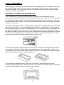
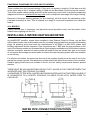
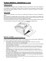
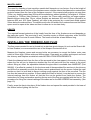
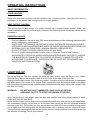
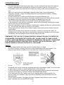
WOODFIRE
INSTALLATING AND
OPERATION MANUAL
Part No. 584347
THE INSTALLATION AND OPERATING INSTRUCTIONS IN THIS
MANUAL APPLY TO THE FOLLOWING MASPORT
WOODFIRES:BELVEDERE
CASHMERE
PANORAMA
PANORAMA DE LUXE
PANORAMA 2000
COLORADO
PROVINCIAL 2, 3, 4.
CONTENTS
INTRODUCTION ................................................................................. 3
FREE STANDING MODELS - INSTALLATION
UNPACKING ....................................................................................... 4
ASSEMBLY ......................................................................................... 4
POSITIONING ..................................................................................... 5, 6
HEARTH REQUIRENENTS ................................................................ 7
CORNER HEARTHS ........................................................................... 8
HEARTH CONSTRUCTION ................................................................ 9
INSTALLING THE FLUE ..................................................................... 9
FIXING IN POSITION.......................................................................... 9
FINAL ASSEMBLY .............................................................................. 10, 11
INSTALLING A WATER BEATING BOOSTER .................................... 11
IN-BUILT MODELS - INSTALLATION
IDENTIFICANON ................................................................................ 12
UNPACKING ....................................................................................... 12
INSTALLATION REQUIREMENTS...................................................... 12
FIREPLACE ........................................................................................ 12 .
MANTEL-SliELF .................................................................................. 13
HEARTH .............................................................................................. 13
INSTALLING THE FIREBOX AND FLUE ............................................ 13
OPERATING INSTRUCTIONS - ALL MODELS
BASIC INFORMATION ........................................................................ 14
LIGHTING UP ..................................................................................... 14
OPERATING HINTS ............................................................................ 15
SAFETY .............................................................................................. 15
MAINTENANCE .................................................................................. 16
THIS BOOK CONTAINS IMPORTANT INFORMATION. PLEASE
KEEP IT IN A SAFE PLACE FOR FUTURE REFERENCE.
2
INTRODUCTION
In the interests of your safety, most building regulatory Authorities in Australia and New Zealand
require any woodfire installation to comply with the relevant Safety Standard. In Australia, that
Standard is AS 2918-1990, while in New Zealand the Standard is NZS 7421-1990. They may also
have local requirements in addition to those in the Standard so you should approach your local
Building Authority before commencing installation to establish whether you will require a Permit
and whether you will need to meet extra requirements. All MASPORT Woodfires have been tested
to ensure that they will meet the appropriate Standard requirements if the instructions in this book
are followed.
WE RECOMMEND THAT THE INSTALLATION OF YOUR MASPORT WOODFIRE BE CARRIED
OUT BY A SUITABLY QUALIFIED SPECIALIST INSTALLER.
PLEASE ENSURE THAT ONLY COMPONENTS APPROVED BY MASPORT ARE USED FOR TB,
THE INSTALLATION, as substitutes may adversely affect performance and might nullify compliance
with the requirements of your Standard.
This recommendation is endorsed by Australian Standard 3869 - 1991, which states:WARNING: THE APPLIANCE AND FLUE SHALL BE INSTALLED IN ACCORDANCE WITH AS
2918 AND THE APPROPRIATE REQUIREMENTS OF THE LOCAL BUILDING REGULATORY
AUTHORITY.
CAUTION: MIXING OF APPLIANCE OR FLUE SYSTEM COMPONENTS FROM DIFFERENT
SOURCES OR MODIFYING THE DIMENSIONAL SPECIFICATION OF COMPONENTS MAY
RESULT IN HAZARDOUS CONDITIONS. WHERE SUCH ACTION IS CONSIDERED, THE
MANUFACTURER SHOULD BE CONSULTED IN THE FIRST INSTANCE.
AS 3869 - 1991 also states, in relation to woodfires using water heating devices:WARNING: DO NOT CONNECT TO AN UNVENTED HOT WATER SYSTEM. INSTALL IN
ACCORDANCE WITH THE RELEVANT AUSTRALIAN STANDARD FOR INSTALLATION OF
HOUSEHOLD TYPE HOT WATER SUPPLY SYSTEMS AND THE APPROPRIATE
REQUIREMENTS OF THE RELEVANT REGULATORY AUTHORITY.
Obviously installers in New Zealand should follow this advice, looking to the appropriate New
Zealand sources for guidance.
Some areas in New Zealand have been designated as Clean Air Zones, and the MASPORT
Cashmere and Provincial 2 have been approved for use in those areas, provided that: (I) No modifications are made to the appliances.
(II) No water heating device is fitted.
(III) No coal is used as a fuel.
3
FREE STANDING MQDELS (See page 12 for in-built models). ‘JNPAQKING
After removal of the shipping carton, retrieve the door handle from the plastic bag just inside the
flue socket, and fit it to the door. Also press the heat output control knob firmly onto its mounting
which will be found adjacent to the wedge shaped heat control decal. Open the door and take out
all loose parts. You may find it more convenient to lift the door from its hinges at this stage.
Remove and discard the four bolts holding the woodfire to the shipping pallet.
remove the woodfire from the pallet, lifting only from the lower edge of each side. DO NOT LIFR
FROM ANY OTHER POINTS.
ASSEMBLY OF FREE-STANDING MODELS
If your model is not a COLORADO, roll it carefully onto its back, using the flattened carton to
protect the floor if necessary. The COLORADO is best assembled by lowering the firebox assembly
onto the upright pedestal assembly.
Taking care that the removable panel of the pedestal will be at the rear of the woodfire,
and that on all models except the low-base PANORAMA a heat deflector is positioned between the
firebox and the pedestal, attach the pedestal to the firebox using the four 6mm bolts provided. The
large heat deflector with four turned-up edges has the tum-ups toward the bottom of the firebox.
Some heat deflectors have a cut-away portion to accommodate a fan accessory. This cut-away
goes at the rear.
If your woodfire has pedestal trims, these are to be clamped between the pedestal and the pedestal
foot. the simplest way to do this is to hold the trims in position with sticky tape before fitting the foot
using the four screws provided. Position the trims accurately before fully tightening the screws.
The bottom heat deflector on the low-base PANORAMA is fitted by slipping it into the base AFTER
it has been assembled to the firebox. Be sure that the turned ends of the low-base PANORAMA
bottom heat deflector will point towards the floor, not the
firebox.
Roll your woodfire carefully back into the upright position.
The PANORAMA and PANORAMA DE LUXE have an external rear heat deflector. Fit
this by withdrawing four screws at the rear of the woodfire.
4
POSITIONING YOUR FREE-STANDING WOODFIRE
Free-standing woodfires must not be installed in a fireplace or alcove, or under a ceiling of less
than normal height. No wall or other immovable object may be closer to the front of the woodfire
than one metre.
Finalise the installation position for your woodfire only after considering the necessary stove-towau distances (See Table below) and checking the practicability of installing the flue system through
the ceiling and roof. As a guide, the flue shielding in the ceiling space will have a diameter of
approximately 300mm, and this must be installable without the removal of structural beams.(Contd.
on page 6)
AUSTRALIA
MINIMUM WOODFIRE TO WALL DISTANCES (millimetres) WHEN
FITTED WITH A 200mm DIAMETER SEMI-PERFORATED FLUE HEAT SHIELD
With 900mm Internal Deflector
Without Internal Deflector
MODEL
A
B
C
D
E
F
A
B
C
D
E
F
Belvedere
150 300 315 615 100 440 150 300 315 615 185 525
Cashmere
125 250 290 565 100 440 175 250 340 565 185 525
Panorama Deluxe
125* 275 250 625 125 450 225* 275 350 625 125 450
Panorama 2000
75
175 260 520 75
450 200 200 385 545 75
450
Colorado
100 200 380 380 50
450 150 200 330 880 75
475
All clearances are baswed on the use of a recommended flue kit and semi-perforated flue heat shield
RECOMMENDED FLUE OPTIONS
1. Shamic #1A, Floate super single with the appropriate Flue Heat Shield option
2. Default flue kits (AS 2918) such as Korvest (Default) or Shamic #3BV, again with the appropriate Flue Heat
Shield option
* Measured to rear of heatshield
5
POSITIONING YOUR FREE-STANDING WOODFIRE (Contd.)
Detailed dimensional requirements for the flue installation are included with every MASPORT
approved flue system.
If a water heating accessory is to be fitted, a further positioning restraint is the need to be close to
your hot water storage cylinder (See page 11).
Flue installations other than strictly vertical ones are possible. See AS 2918 or NZS 7421 for
information on flues passing through walls and eaves.
NEW ZEALAND
MINIMUM WOODFIRE TO WALL DISTANCES (millimetres)
With Flue Heat Deflector
MODEL
Belvedere
Cashmere
Panorama
Panorama Deluxe
Panorama 2000
Colorado
* Measured to rear of heatshield
A
150
100
150*
150*
50
150
B
300
200
300
300
150
350
C
315
265
275
275
235
330
D
615
515
650
650
495
730
6
E
50
50
125
125
75
50
Without Flue Heat Deflector
F
390
390
450
450
450
450
A
400
300
450*
450*
250
550
B
400
250
350
350
225
400
C
565
465
575
575
435
730
D
715
565
700
700
570
780
E
250
225
275
275
75
350
F
590
565
600
600
450
750
HEARTH REQUIREMENTS - FREE-STANDING WOODFIRES
Unless your woodfire will be standing on a fireproof floor which extends at least 150mm from the
sides and rear of the cabinet, and 400nun forward from the door glass, it will be necessary to
provide floor protection.
Some stoves require a hearth just to protect against ash spillage, while others require a hearth
which also has insulating properties to prevent the floor from overheating.
Having now decided exactly where your woodfire will be installed, you will be able to estimate the
minimum size of hearth you will need. Where the minimum requirements bring the edge of the
hearth nearly to a wall, it is better to extend the hearth to meet the wall. In fact it is prudent to
increase all dimensions by moving up to the next available size so that precise positioning of the
woodfire on the hearth will not be needed.
AUSTRALIA
Belvedere
Cashmere
Panorama Deluxe
Panorama 2000 §
Colorado §
A
875
875
875
875
875
B
750
750
765
770
820
C
300
300
300
300
300
D
120
120
85
95
60
F
0
0
0
0
0
G
165
165
125*
185
180
H
450
450
465*
470
520
J
635
635
700
690
760
K
200
200
200
200
200
NEW ZEALAND
Belvedere
Cashmere
Panorama
Panorama Deluxe §
Panorama 2000
Colorado §
A
935
875
880
880
880
880
B
900
950
990«
865
870
920
C
350
400
425«
300
350
300
D
150
120
90
90
95
60
F
100
100
100*
100*
50
100
G
165
165
125*
125*
185
180
H
450
450
465*
465*
470
520
J
635
635
700
700
690
760
K
200
200
200
200
200
200
*
§
«
Measure to rear heat shield
Installation not requiered in hearth
Reduce by 50mm if hearth is at least 50mm above floor
7
CORNER HEARTHS
While the information in the previous section details the MINIMUM size of hearth necessary to
comply with the Safety Standards, it will frequently be desirable to use a somewhat larger area of
hearth for Aesthetic considerations. A particular example is when the woodfire is installed diagonally
in a corner. A neater appearance will result if the hearth is carried right into the comer and is
shaped as shown below. The chart facilitates calculation of the MINIMUM dimensions required for
hearths of this shape. The minimum allowable values for dimension ‘E’ are given in the tables on
pages 5 and 6. If ‘E’ is greater than the minimum value, naturally the overall hearth size requirements
increase accordingly.
Australia
X
900
900
925
945
1025
Belvedere
Cashmere
Panorama
Panorama Deluxe §
Panorama 2000
Colorado §
Y
600
600
615
640
700
New
Zealand
X
Y
950 625
950 700
1025 700
925 615
995 670
1025 700
NOTE: YOUR SPECIFIC MEASUREMENT FOR ‘E’ MUST BE ADDED TO ‘X’ AND ‘Y’ TO
FIND THE APPROPRIATE MINIMUM HEARTH DIMENSIONS
SEE PAGE 5 OR 6 FOR MINIMUM HEARTH DIMENSIONS
8
HEARTH CONSTRUTION
In cases where no insulating properties are needed in the hearth, all that is required is a surface
which will not suffer damage if embers should be accidentally spilled on it. Obvious choices are
sheet metal, ceramic tiles and bricks. There must be no gaps in the construction which might allow
embers to penetrate to the floor.
Where the hearth needs insulating qualities, these can be provided in Australia by a 25mm sheet
of HARDITHERM 700 with a 25mm air gap underneath (created by 100 mm square heat resistant
blocks positioned over the floor joists), or either two 15mm thick sheets of ROCBOARD or a 12mm
fibre cement sheet placed directly on the floor. In New Zealand, the insulation can be two layers of
MICORE 160 (each 16mm thick) or one layer of WOODTEX (35mm thick). In both countries, to
provide a durable surface, these materials can have a layer of ceramic tiles, slate etc. glued on top.
A trim moulding can be fitted around the edges of hearths not spaced above the floor. Spaced
hearths should have at least half the length of two opposite sides open to allow air to flow through
freely. If carpet could be laid subsequently, the 25mm air gap should be increased to 35mm.
Information on MICORE hearth construction can be obtained from FLETCHER WOODPANF-LS
Ltd, P.O. Box 12139 Penrose, Auckland, or their Agents.
Materials which are NOT suitable as insulating hearths are bricks and concrete when they are in
contact with the, flooring material
INSTALLING THE FLUE
You MUST use a flue system which is approved by MASPORT and which complies with AS 2918 1990 or NZS - 7421 1990 as appropriate. The flues and flue heat shields recommended in Australia
are detailed in the table on page 5. In Australia, flue heat shielding must be fitted unless all heat
sensitive material in the vicinity is at least 450mrn away from the flue surface.
In New Zealand we recommend the use of genuine Masport flue kits. ‘Me flue MUST be
installed in accordance with the detailed instructions accompanying it. A polished stainless steel
heat deflector (I 200mm long) must be fitted at the back of the flue, directly above the stove, unless
all heat sensitive material nearby is separated from the woodfire by at least the distances shown in
the right hand side of the table on page 6.
In New Zealand, all PANORAMA models and the COLORADO must have a cap fitted at the top of
the flue heat deflector to control ceiling temperatures. This cap is shipped with the woodfire.
FIXING THE WOODFIRE IN POSITION
Once the flue shielding system has been installed through the ceiling and roof, the woodfire can be
placed in its approximate position on the hearth, and the flue pipes installed. Finally adjust the
stove position making sure the flue is vertical and that the necessary minimum woodfire-to-wall
distances are being achieved. In New Zealand, NZS 7421 requires that the woodfire and hearth be
secured to prevent shifting in the event of an earthquake. With the style of insulating hearth
suggested, this is best done by fastening the woodfire right through the hearth to the floor, using at
least two 10 gauge screws or the equivalent sizes of coach bolts or spring toggle fasteners.
9
FINAL ASSEMBLY
Before lighting the woodfire, the positions of the internal castings must be checked in case they
have shifted during transit. No force should be required to fit these castings, and they can be
removed, if desired, for flue cleaning. However, they MUST be in place, and in good condition,
when there is a fire in the firebox.
BELVEDERE, CASHMERE AND PANORAMA 2000.
These models have the same internal castings except that in the CASHMERE the rear
lower wall is replaced by firebricks. The rear lower wall fits parallel to the back of the firebox with
the angled edge uppermost and the narrower bottom edge resting in the notches cut in the fins
across the bottom of the firebox. The top lug fits behind the lower edge of the firebox rear upper
wall when it is in place.
The firebox rear upper wall is an ‘L’ shaped casting which sits on a ledge at the top of each side
wall. ‘Me short leg of the ‘L’ ties horizontal and faces the front of the firebox. It is not necessary
to remove the secondary air tube in the Cashmere to fit or remove this casting. If necessary, lift it
into position by angling one end up and over its ledge and moving it as far as possible toward
the side of the firebox. Lift the other end up over its ledge and bring the casting back to a central
position where it will drop into its correct place. As it does so, make sure the lug on top of the
rear lower wall is behind the bottom edge of the rear upper wall.
The firebox ceiling has an angled rib which has a step in its height. This angled rib goes on top
and toward the front of the firebox. Again this casting rests on top of the ledges. Lift one end
over the ledge at a time as before. When finally in position, its rear edge tucks under the ‘joggle’
along the front edge of the rear upper wall casting.
The Cashmere is supplied with four fire bricks. Two bricks fit across the back with their
chamfered comers positioned to clear the tie rods in the comers of the firebox, and one brick fits
each side with its chamfered comer facing the door opening.
10
PANORAMA, PANORAMA DE LUXE AND COLORADO,
These models have two internal castings. If they are, not already in position, fit the large one first
in the same way as the ‘L’ shaped casting is fitted into the Belvedere (See the previous section).
Then fit the smaller casting, taking care that it is the correct way round. Hook it up onto the supporting
ledges and be sure it is pushed all the way back until it overlaps the front edge of the larger casting.
Removal of the larger casting (perhaps for flue cleaning), will first require the dismantling of the
Colorado secondary air tube. This is retained by a single 6 mm screw accessible from inside the
firebox.
ALL MODELS
Finally, refit the door, if necessary, and spread the sand provided evenly over the bottom of the
firebox before lighting the first fire.
INSTALLING A WATER HEATING BOOSTER
Any MASPORT woodfire, except those installed in New Zealand Clean Air Zones, can be fitted
with a water booster tube as all models have the mounting holes provided but covered with blanking
plugs. All plumbing work must meet the requirements of AS 3500.4 or NZS 4603 unless local
building regulations dictate otherwise. Pipe connections are I” BSP and the pipe positions on the
rear of the various models are illustrated below. Special piping methods must be followed to ensure
effective circulation, and the hot water cylinder will need to have an internal riser pipe to two thirds
of its height to discourage unwanted water circulation through the piping system when the woodfire
is not burning.
For effective circulation, the pipes from the rear of the woodfire should rise at the rate of one in five
toward the storage cylinder, and ideally the cylinder should be within three metres of the woodfire.
Detailed piping instructions are included in the kit, but two safety requirements deserve special
mention.
THERE MUST BE NO NON-RETURN OR SHUT-OFF VALVES IN THE PIPES BETWEEN THE
WOODFRE AIND THE STORAGE CYLINDER.
A WOODFIRE FITTED WITH A WATER HEATING BOOSTER MUST NOT BE FIRED UNLESS IT
IS CONNECTED TO A VENTED STORAGE CYLINDER FILLED WITH WATER FREE TO
CIRCULATE.
WATER PIPE CONNECTION POSITIIONS
11
IN-BUILT MODELS - PROVINCIAL 2, 3 & 4
IDENTIFICATION
The Provincial 2 is equipped with a secondary air tube and has firebricks. This model is approved
for installation in New Zealand Clean Air Zones. Provincial 3 has a secondary air tube, but has a
lower rear wall casting instead of firebricks. Provincial 4 is similar to Provincial 3, but has no
secondary air tube.
UNPACKING
The Provincial is packed in two cartons, one containing the firebox, the second containing the
fascia.
After removal of the shipping carton from the firebox, retrieve the door handle from the plastic bag
just inside the flue socket, and fit it to the door. Open the door and take out all loose parts. You may
find it more convenient to lift the door from its hinges at this stage.
Carefully tip the firebox onto its back, using the flattened carton and the cardboard insert to support
it in a level position. Remove the shipping pallet by unscrewing the shipping bolts.
INSTALLATION REQUIREMENTS
Please read the INTRODUCTION on page 3, as this applies also to in-built models. FIREPLACE.
For a safe installation the following matters must be attended to.
•
The fireplace and chimney must be thoroughly cleaned and checked for soundness.
•
The chimney must not connect to a second fireplace.
•
The joint between the chimney face and the fireplace surround must be checked and sealed
to prevent leakage if necessary.
•
The fireplace recess must have a non-metallic heat resistant surround extending at least
455mm each side of the recess and up to at least 810mm above the base of the fireplace
recess.
•
In New Zealand, the fireplace and chimney must comply with all the requirements of
NZS 1900 Chapter 7 - 1985, except that the specified separation from timber construction
need not be complied with.
•
A flue pipe must be fitted right up the chimney, and the space between the flue pipe and
chimney must be ventilated at the top. In Australia the area of this vent must be not less than
10,000mm², while in New Zealand it is 13,000mm². The vent must be fitted with means to
prevent significant ingress of water and debris.
•
Provision must be made for sweeping the flue without any dismantling other than is normally
done by the chimney sweep.
12
MANTEL-SHELF
The need for shielding a heat sensitive mantel-shelf depends on two factors. One is the height of
its undersurface above the floor of the fireplace recess, and the other is the distance the undersurface
projects forward from the face of the fireplace surround. If the mantel-shelf projects not more than
75mm, any height greater than 955nim will be satisfactory without shielding. At heights of 1030mm
(Australia) or 1155mm (New Zealand), or greater, the 75mm width restriction no longer applies.
Mantel-shelves wider than 75mm, whose heights are between 955 and 1030nun (Australia) or
between 955 and 1155 (New Zealand), will need to be protected by a metal heat shield spaced
20mm below the undersurface. The shield must be the full width of the undersurface and the 20mm
space must be open at the sides and front to allow air to circulate freely.
HEARTH
The required forward extension of the hearth from the face of the fireplace surround depends on
the particular model. The provincial 2 and 3 models require a 400mm extension, while IN NEW
ZEALAND the Provincial 4 needs 300mm. The hearth should be at least 900mm long.
INSTALLING THE FIREBOX AND FLUE
The flue recommended for use in Australia is a stainless steel chimney kit such as the Shamic #4.
In New Zealand, we recommend the use of the Masport Provincial flue kit.
Measure the fireplace recess and remove bricks as necessary to accept the firebox outer case
which is 56mm high, 590mm wide and 460mm deep. Clear away any rubble and inspect and’ seal
the chimney and fireplace as detailed under INSTALLATION REQUIREMENTS.
Check the distance back from the face of the surround to the clear space in the centre of chimney
where the flue will run to determine whether the flue will mate with the flue socket in the stove
without fitting an offset. An adjustable shielded flue pipe offset is available from MASPORT (Part
985406). If an offset is needed, fix it to the lower end of the assembled flue sections in the chimney
and lift the flue assembly up while the firebox case is pushed back into the recess. Adjust the case
position so that it is level and its flange is sitting snugly against the face of the surround. The flue
can then be lowered into position. If space above the case is limited, it may be best to remove the
internal castings from the firebox so that the flue can be guided from inside the firebox. The
instructions for fixing and weather-proofing the top end of the flue are supplied with the flue kit. The
procedure for fitting the internal castings is the same as for the BELVEDERE final assembly. (See
page 10).
Finally, screw the fascia into place, fit the firebox door and spread the sand provided in the base of
the firebox before lighting the first fire.
13
OPERATING INSTRUCTIONS
BASIC INFORMATION
DOOR HANDLES
Swing the door open and shut with the handle in the 1 o’clock position. Latch the door shut by
pushing in on the handle and turning it to the 4 o’clock position.
HEAT OUTPUT CONTROL
This control has a sliding action. It is clearly marked with a wedge shaped symbol. Slide the
control toward the wide end of the wedge to increase the heat output and toward the narrow end to
decrease it.
ESSENTIAL ADVICE
•
•
•
•
Correct installation, the use of only DRY wood and adherence to the following instructions will
ensure satisfactory performance.
MAKE SURE THE MINIMUM WOODFIRE-TO-WALL DISTANCES SHOWN ON PAGES 5
AND 6 ARE ALWAYS MAINTAINED BETWEEN THE WOODFIRE AND ANY BEAT SENSITIVE
MATERIAL SUCH AS FURNITURE, WINDOW DRAPES, FIREWOOD ETC.
DO NOT ATTEMPT TO BURN LIQUID FUELS OF ANY KIND.
Do not fit a water heating booster or bum coal in a Clean Air Zone in New Zealand.
WOODFIRFS FITTED WITH WATER HEATING BOOSTERS MUST NOT BE LIT UNLESS
THE BOOSTER IS CONNECTED TO A VENTED STORAGE CYLINDER FELLED WITH
WATER FREE TO CIRCULATE. THERE MUST BE NO SHUT-OFF OR NON-RETURN
VALVES IN THE PIPING SYSTEM.
LIGHTING UP
Before lighting the first fire, spread the sand provided evenly over the floor of the firebox.
Subsequently, always leave sand or ash up to the level of the tops of the floor ribs.
Slide the heat output control fully to the hot position. Crumple up one or two sheets of newspaper
and place them in the centre of the firebox. Build a pyramid of thin, dry kindling wood on the paper
with some heavier pieces on top. Light the paper at the bottom and when the fire has ‘caught’, latch
the door shut firmly.
WARNING -
DO NOT USE ANY FLAMMABLE LIQUID SUCH AS PETROL,
KEROSINE, OIL ETC. TO START OR REKINDLE THE FIRE.
When the kindling is well alight, open the door and carefully add some larger pieces of wood.
Close and latch the door firmly.
Move the heat output control away from the maximum position only after the fire is well established.
We recommend running at full heat for 30 minutes after lighting as this will minimise creosote
build-up in the flue. The control can then be set wherever desired. A new woodfire should not be
run at higher than half setting after the first 30 minutes until it has been used for a total of 8 hours.
The special high temperature paint on the firebox will emit some smoke as it cures during the first
few minutes of running. This is quite normal.
14
OPERATING HINTS
•
•
•
•
•
•
•
•
For clean burning and maximum heat output, use only wood that has been thoroughly air
dried in a sheltered stack preferably for at least 12 months. If the use of moist fuel is
unavoidable, add it only when the fire is really hot, mixing it with a large proportion of dry
fuel.
Add fuel in small amounts reasonably frequently rather than in large quantities at
infrequent intervals. A large fuel charge drops the fire temperature suddenly, causing
inefficient combustion.
A small intense fire is much more efficient than a large smouldering one.
Do not bum timber which has been chemically treated because the chemicals can corrode
the appliance and may create poisonous gases and dangerously toxic ash.
• Do not bum salt water driftwood as salt will corrode the woodfire and flue.
In the interests of more efficient combustion, switch off the accessory circulating fan when
the fire is burning at low heat outputs.
Move the heat output control to maximum briefly before opening the door on a slow burning
fire. This will help clear away any smoke in the firebox.
Always open the door slowly. Do not leave it open unnecessarily as this lets the fire bum
uncontrolled.
Always close the door firmly and latch it securely to ensure a good air seal. Minor air
leakage around the door seal can be corrected by transferring a washer on the door latch
mechanism. Serious leakage must be fixed by fitting a new seal.
REMEMBER, FOR THE FIRE TO DRAW PROPERLY, AIR MUST BE ABLE TO ENTER THE
ROOM WHERE YOUR WOODFIRE IS INSTALLED. YOU MAY HAVE TO LEAVE A DOOR
SLIGHTLY OPEN AND PERHAPS A WINDOW ELSEWHERE IN THE HOUSE IF YOUR HOME
IS OF MODERN AIRTIGHT CONSTRUCTION. LEAVING THE DOOR OPEN WILL HELP
SPREAD WARMTH THROUGH THE REST OF YOUR HOME.
SAFETY
•
Always keep children well away from the woodfire when it is alight
•
Do not put furniture, clothing, firewood or other combustibles near the woodfire. The
minimum safe distance is 400mm from the sides and 1 metre from the front
•
•
•
•
•
•
Do not leave the fire unattended with the door open.
Accidental fires can be caused by wrapping seemingly cold ashes in paper. It is much safer
to place ashes outside in a metal container with a close fitting lid.
If a fire is burning up inside the flue, slide the heat output control to the low heat position
and call the Fire Service. DO NOT OPEN THE WOODFIRE DOOR.
If you have had a flue fire, inspect your flue for damage before lighting another fire.
Do not modify your woodfire in any way without obtaining written permission from the
Manufacturers.
Do not use the woodfire if the glass is broken. Replace it only with the correct ceramic
glass, available from your MASPORT dealer.
15
MAINTENANCE
ASH REMOVAL
This should be necessary only very occasionally. Simply shovel out any excess, always leaving a
bed of sand or ash to the tops of the ribs.
CLEANING THE GLASS
Usually a good hot fire will bum away any deposits left from a long slow bum. If desired, a proprietary
oven cleaner can be used.
CLEANING THE CABINET
A damp rag with a touch of household detergent is sufficient to maintain the finish.
CLEANING INSIDE
If you wish to clean the flue or clear away creosote debris, the internal castings can be easily
removed. See installation instructions.
CLEANING THE FLUE
This should be needed about once a year or more frequently under adverse conditions. Some
signs of creosote and soot build-up are lack of adequate draught, smoking when the door is opened
and a dull thud when the outside of the flue is tapped. A blocked flue can be cleaned only by
sweeping. DO NOT USE CHEMICAL CHIMNEY CLEANERS.
FLUE INSPECTION
Do this regularly to ensure that the flue is sound, particularly the metal base of enamelled flues.
HEAD OFFICE - NEW ZEALAND
1 - 37 Mt Wellington Highway
Panmure, Auckland 6
Phone: (9) 571 1200
Fax:
(9) 571 5864
16
HEAD OFFICE - AUSTRALIA
P.O. Box 533, Braeside
Postcode: 3195
Phone: 1300 366 225
Fax:
1800 035 594