1
United States Patent [19]
[11]
4,132,142
Campbell
[45]
Jan. 2, 1979
[54] METHOD AND APPARATUS FOR
REPRODUCING A MUSICAL
PRESENTATION
'
_
OTHER PUBLICATIONS
Service Manual for Teledyne Piano Recorder/Player,
Model PP-l, Assembly No. ATL-3288, Oct. 20, 1975.
.
Assembly Instruction for Teledyne Piano Recorder/
Us] Invent“ Pep“ M- c‘m'l’be'l' Lew‘sburg'
'
Player, Model PP-l, Assembly No. ATL-3288, Jul. 10,
em
i
.
1975.
_
.
>
Primary Examiner-Stanley J. Witkowski
[73]. Asslgnee' 1:23;‘: ggymes’ Inc" Los
Attorney, Agent, or Firm-Jim Zegeer
[21] App}. No,; 681,093
There is disclosed a method and apparatus for repro
[57]
'
ABSTRACT
ducing a musical presentation wherein musical data,
,_
from such presentation, such as keyboard actuations of
[22] Flled:
Apr‘ 28’ 1976
a keyboard-type musical instrument, is encoded and
'
stored in a code which has information contained in the
[51]
Int. cl.Z ..... ..
G101: 1/00; (3106 3/04
transitions only and the sense and direction of such
[52]
US. Cl. ..................... ............... .. 84/115; 84/462;
transitions are ign°f¢¢ This avoids Several major draw
84/])}(}, 29
backs of bi-phase level code previously disclosed in the
[58] ‘Field of Search ..; ................. .. 84/l.02, 1.03, 1.28,
prior art because the (1) phase of the Signal need not be
34/115, 461’ 462, DIG‘ 29
maintained and, (2)-the bi-phase level code cannot be
recovered following a dropout until a 1-0 or a 0-1 transi
6
R f
[5 1
Cit 6
e ereuces
tion occurs.
6
US PATENT DOCUMENTS
3,539,701
11/1970
3,647,929
3/1972
’ _
There is also disclosed a data dropout detection system
for assuring that the wrong music is not played.
Milde
84/128
Milde, Jr.
84/ 1.02 X
13 Claims, 8 Drawing Figures
IQJ
Q
g
M /I0
%
ll-l
[l2
U’,
_
,
g
;
5
E
a
g
Q
[I3
BIPHASE
TAPE
SPACE/MARK
,6
= RECORD 1
Bl- PHASE
SPACE/MARK
_
2 l
g
31'
I
.2 i
LL]
35
LE ‘I
c;
ENCODER
PLAY
.
DECODER
‘
5 IE
“5i
5
u.
H N H-S
_
GEN. \l0 5
SYNC.
TIMING
~\
SOURCE
T
glllE RECOVERY
I DROP OUT
SYNC. COUNTER
BIT 8| FRAME
COUNTER
_
g
US. Patent
Jan. 2, 1979
Sheet 2 of6
4,132,142
5nQ-h
B.
2595m
6
N
5
mm
3
1
4,132,142
2
in a musical system. In all cases, striking the wrong note
METHOD AND APPARATUS FOR
REPRODUCING A MUSICAL PRESENTATION
sounds much worse than striking no note at all. The ?rst
out” at selected times to reactuate the actuator elements
multiplex recording of key switch actuations, one of
which is a frequency multiplexing scheme whereas the
brator. The output of this retriggerable monostable
multivibrator stays high after a positive going edge is
applied to the input for a time determined by an RC
timing circuit. As long as the positive going edges occur
in less than the predetermined time, the monostable
multivibrator is reset and begins timing out again. Thus,
if due to a slow tape speed, data dropout, recorder
other is a time division multiplexing scheme. Various
stopping, or no information recorded on the tape, no
problem is that when the recorder is started, or when
the electronics are ?rst powered on, there is no syn
BACKGROUND OF THE INVENTION
5 chronization of the internal electronic counters to the
Automated musical instruments have been known for
data that is recovered from the recorder until the ?rst
many years. Automation of keyboard actuations has
sync code is received. If this is permitted to happen, it
been accomplished in the piano, organ, carillon, etc.
can cause wrong notes to be struck at the beginning of
when the keyboard actuations are translated to perfora
replay. The second problem is of more serious conse
tions in a paper tape, which constitutes a storage me 10 quence, depending on the code used, because if in the
dium, and then these recorded actuations are used to
middle of the replay the tape has a dropout, the elec
actuate the instrument to produce the music. In
tronics lose the sync and wrong notes are struck. In any
punched paper memories, such as the player piano or
fast scan multiplex system, all notes that are on at the
organ, there is typically one channel for each key on the
time of the dropout may be shifted either up or down
piano or organ keyboard. In the electri?cation of such
the scale until the sync code is recovered again. Finally,
instruments, the changeable memories of various types
accidental detection of a wrong sync code due to noise,
have been used. For example, in Cooper US. Pat. No.
misadjustment of controls or the data information con
3,380,026, magnetic core elements are used as memory
tained in the sync code causes the playing of wrong
devices into which are “read” the condition of a plural
music because of the improper synchronization.
ity of actuator elements such as the stops or coupler 20 According to the present invention, a data detector is
switches of an organ. These stored actuations are “read
provided which has a retriggerable monostable multivi
and reproduce the stored musical information. Inexpen
sive magnetic tape cassettes are disclosed in the prior
art, as in Schmoyer U.S. Pat. No. 3,388,716 and in En 25
glund US. Pat. No. 3,604,299, both of which disclose
forms of encoding systems have been utilized, as, for 30 edge occurs so the device times out and clears the sync
example, in Peterson U.S. Pat. No. 3,683,096, a recur
counter and the input register, both of which prevent
ring frame of pulses has one pulse therein for each of the
notes from being struck or being held in a closed state.
key switches of the musical instrument and a pulse mod
To insure that power is on at the start of the tape
i?er is utilized for modifying in a predetermined manner
record or after data dropout of the tape that no wrong
a speci?c pulse in each frame and these modi?ed pulses 35 notes are struck, I provide a sync counter which counts
are thereafter decoded. In Wheelwright U.S. Pat. No.
three sync codes before allowing any note to be struck.
3,771,406, the key switch actuations are encoded into a
This sync counter allows for the posssibility that a sync
?ve bit binary code which is loaded into a shift register
code could possibly occur randomly in the data infor
for a parallel to a serial conversion; and in Maillet US.
mation and rejects the false sync code. In essence, this
Pat. No. 3,789,719, key switch actuations are loaded 40 requires two complete frames of data to be occurred
directly into a shift register which, for a piano, would
before any notes may be struck after any disturbance
have 88 stages, one for each key, and additional ones for
causes the data detector or sync detector gates to indi
the other controls of the unit, and a key pulse is gener
cate a malfunction.
ated by the last stage of the shift register and these
In the bi-phase level coded waveform as disclosed in
pulses along with the clock pulse are recorded directly 45 the Vincent patent, there are two signi?cant drawbacks,
upon the tape for subsequent playback. Finally, in Vin
the ?rst of which is that the phase of the signal must be
cent US. Pat. No. 3,905,267, the keyboard switch actu
maintained by the system if it be recorded on tape and,
ations are passed through a multiplexer to serialize the
secondly, if a dropout occurs the l-O relationship cannot
key switch actuations which are then encoded in a bi
be recovered until a 1-0 or 0-1 transition occurs in the
phase level encoder, best shown in FIG. 6 and the
NRZ waveform. What actually occurs in the playing of
waveforms of FIG. 7 of US. Pat. No. 3,905,267. The
music is that all zeros (no music) become all ones (all
‘oi-phase level data may be further encoded to provide a
notes being played). This also occurs during the stop
double density encoding shown in the waveform dia
ping and starting of the recorder.
grams of FIG. 9 of US. Pat. No. 3,905,167 which is
_ I have discerned that a number of the problems in
subsequently recorded upon a magnetic tape, played 55 volved in coding systems for musical performances are
back, decoded and demultiplexed for subsequent reactu
that the bi-phase level code requires transition to occur
ation of the piano keyboard.
in both position and sense so that in the playing of mu
‘With respect to all prior art encoding and decoding
sic, all zeros (no music) become all ones (all notes being
schemes, they all have serious drawbacks because they
played). I have determined that the problem with this
appear to be attempts to apply modern electronic tech
coding scheme is that in the recording of keyboard
nology to electronic player pianos but have failed to
music, the information is highly weighted with zeros
really grasp or apply the technology in such a way as to
(no key closures) and, therefore, in accordance with the
make it compatible with the playing back of recorded
invention, a code used for a slow recorder is such that
music. in some prior art systems, if the tape recorder is
the data (ones and zeros) would look like all zeros. The
stopped while notes are being played, the last notes 65 bi-phase (or mark) code, as disclosed at page 42 of the
played may be held on which is undesirable at best and
Telemetry Standards Document 106-71 (a portion of
may cause damage to the system. Moreover, there are
which is reproduced in FIG. 2 hereof), has as zeros
several places that will cause wrong notes to be struck
information the wide spacing between transitions.
3
4,132,142
There is always a transition at the beginning of each bit
period which can be recovered as the self-clocking
portion of the code. The information is therefore con
tained only in the interbit transitions and not in the
direction and sense of transition as in the bi-phase level
code. Moreover, the data may be inverted and still be
satisfactorily recovered. If a data dropout occurs, the
data detector can immediately regain correct phasing
without errors.
The above and other objects, advantages and features
of the invention will become more apparent when con
actuations are sensed by the digital multiplexer l2, one
at a time, and in a generally sequential fashion. How
ever, if no transpositions are contemplated, it is not
necessary that they be sequentially examined, it being
evident from the description given in connection with
FIGS. 3A and 3B that they may be looked at or scanned
in groups and in any fashion or order, the only criteria
being that the position of the particular switch in its
scan time be maintained in the entire system. The timing
source T is shown in FIG. 3B, and is described in the
sidered in light of the accompanying drawings wherein:
section hereafter entitled “Multiplexing”.
The multiplexer thereby translates the parallel data of
DESCRIPTION OF THE DRAWINGS
the key switch actuations to a serial data stream along
its output line 113. This data is then encoded to a bi-phase
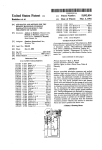
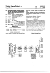
FIG. 1 is a block diagram of an electronic record and
player system for musical instruments;
FIGS. 2(a), (b) and (c) are a sequence of waveform
diagrams taken from page 42 of Telemetry Standards
Document 106-71;
FIGS. 3A and 3B taken together, are a detailed sche
matic of the key switch scanning and encoding system
incorporating the invention;
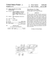
FIGS. 4A and 4B, taken together, are a detailed sche
matic of the playback electronics;
space (or mark) signal in bi-phase space (or mark) en
coder 14% and then recorded on a tape in tape recorder
15. It will be appreciated that tape recorder 15 is con
ventional in all material respects and need not be dis
closed or described in any detail herein. It can be the
same as is disclosed in any of the prior art patents re
ferred to earlier herein for recording digital data on tape
or as shown in the included “Service and Installation”
Manuals.
Such tapes may be recorded beforehand by known or
FIGS. 5(a-j) are illustrative waveform diagrams with 25 accomplished artists or in home recordings, or rere
the various points in FIGS. 3A, 3B, 4A, and 4B indi
cordings of punched paper rolls, etc. In the case of
cated to the right of each waveform, for convenience,
recording made by stars, performers and the like, these
the data bits in each bit period or cell are shown at the
recordings may be sold separately and apart from the
top and bottom of FIG. 5; and
recording system per se. That is to say, a tape may be
FIG. 6(a) is a waveform diagram of the “D Pulse”
encoded and the strings of a piano, for example, struck
FIGS. 4A and 4B illustrating various problems which
or actuated by hammers or the like in exactly the same
can occur in the playback of a recorded musical presen
tation and FIG. 6(b) is a waveform diagram of the
“blank” pulse corresponding thereto.
DETAILED DESCRIPTION
Attached hereto and incorporated herein as an inte
gral part of the disclosure of this speci?cation, is the
“Service Manual” for Teledyne Piano Recorder/Player
Model PP-l Assembly Number 3288 ATL 3263, a pub
lication of the assignee hereof and sometimes referred to
hereinafter as “Service Manual”.
Attached hereto and incorporated herein as an inte
gral part of this speci?cation is the “Assembly Instruc
tion for Teledyne Piano Recorder/Player Model PP-l
Assembly Number ATL-3288 Document Number
ATL-3262”; a publication of the assignee hereof and
sometimes referred to hereinafter as “Installation Man
manner as an accomplished artist would be on a piano
which is set up for playback operation only in the man
ner illustrated in FIGS. 4A and 4B hereof‘. In other
35 words, one need not equip a piano for the record func
tion disclosed herein.
On playback by the tape recorder 15, the bi-phase
space (or mark) data appears at the output of a read
head and is fed through correcting networks and ampli
40 ?ers to recover the digital signal. The data from the
read head is approximately a sine wave, but the output
from the ampli?er on line 16 is a square wave signal.
Moreover, the signal from the read head has encoded
therein the clock data which must be recovered and
used in the demultiplexing operation. The time recov
ery, bit dropout, sync counter, bit and frame counter
circuitry is shown in FIGS. 4A and 4B and described in
detail in the section entitled “The Decoder”, which
ual”.
recovers the timing signals, “The Data Dropout Detec
The above publications describe in detail a speci?c 50 tor” which detects the bit dropout, “Sync Counter” for
and preferred embodiment of an electronic player piano
counting frames of sync pulses and the demultiplex and
incorporating the invention de?ned in the claims hereof
latch circuit.
as made and sold by the assignee hereof.
The bi-phase space (or mark) decoder circuit 17 de
Referring now to FIG. 1, the keyboard of a piano is
codes the incoming data on line 16 and applies same to
designated by the numeral 10 and constitutes the key 55 demultiplexer 113 which distributes the data to the ap
board-pedal data source. It could be any musical key
propriate control channels in the storage and solenoid
board source instrument such as a harpsicord, carillon,
actuator circuits 19.
organ, piano, etc., and each output or switch actuation
The playback logic, shown in FIGS. 3A and 3B, also
is indicated by a single line 11-1 through ll-N, the num
decodes the expression bits and provides bass and treble
ber of such output lines corresponding to the number of 60 outputs to control the volume of play.
key switch actuations to be sensed and recorded, for
Referring now to FIG. 2, the waveforms of a se
example, eighty keys (in one embodiment disclosed
quence of data bits (10110001101) are shown in three
herein), the “sustain” and “loud” pedals of an eighty
eight key piano may be sensed. A sequence of synchro
different bi-phase encoding schemes, the ?rst of which
is shown in line A of FIG. 2, namely, the bi-phase level
nizing bits from sync generator 10-8 is provided on line 65 encode scheme. As disclosed in the above-referenced
Ill-S. A multiplexer 12 scans or looks at each individual
Telemetry Publication, this bi-phase level (or split phase
line III-I. . . 11-S in a times sequence which constitutes
Manchester II t 180°), a “one” is represented by a I 0,
and a “zero” is represented by a 0 1. Thus, the sense of
frames. Thus, the key switch, sustain and loud pedal,
5
4,132,142
the transition as well as the position thereof represents
ti
embodiment, there will be one hundred and twenty
data. In the bi-phase space (or mark), shown in line B of
eight bit periods within a given time frame, i.e., the time
FIG. 2, there is a transition at the beginning of every bit
it takes for a pulse to activate output terminal 17 of one
of select circuits U-E. The bit assignments are shown on
period. However, a “one” is represented by no phase
shift, i.e., a zero crossing, at the middle of (or interbit)
Chart 1 of the “Service Manual”; bit positions 89-104
the bit’period. On the other hand, a “zero” in contrast is
represented by a 180° phase shift (i.e., no transition or
are not used and bit position 116 is not used along with
bit positions 1119 and E20. As shown on the “bit assign
zero crossing) at the middle of (interbit) the bit period.
The exact opposite of the bi-phase space (or mark) is
ment chart”, the sustain and soft pedals occupy bit posi
shown in line C of FIG. 2 wherein a transition occurs at
tions H7 and I110 in the frame whereas the bit 105-109
and III-115 are used to activate the bass theme and bass
the beginning of every bit period as in the case of the
theme intensity levels and the treble theme and treble
bi-phase space encoding scheme, but in this case, the
intensity controls, respectively. Finally, bit positions
representations of the one and the zero is exactly the
reverse of that shown for the bi-phase space. Thus, in
either the bi-phase space or the bi-phase mark, the sense
of the transition is ignored and conveys no information
whatever and it is the presence, in the case of the bi
phase mark, or absence, in the case of the bi-phase
space,'of a transition which determines the data. In
1211-1120 are assigned to the synchronizing bits which
are generated when a strobe pulse appears on pin 17 of
U-5, the zero at bit position 127 is a check bit.
accordance with the preferred practice of the present
invention, the bi-phase space or mark encoding format
is utilized since in this case, the predominant number of
data bits is in the zero format so that the data stream
. ENCODING (FIGS. 3A and 3B)
It will be noted that the output of the selection circuit
20
U-Il is in time frames with the data being in non-return
to zero code format. This data (FIG. 5a) is applied as
one input to the encoding circuit. As discussed earlier,
in the recording of keyboard music, the information is
highly Weighted with zeros, that is, there are no key
looks essentially like all zeros and if a data dropout, loss
closures and, therefore, according to this invention, the
of sync, etc. occur, the system immediately picks up 25 code is such that for a slow recorder the data (ones and
playing zeros, e.g. not striking any notes. Some texts
zeros) would all look like zeros. As shown at page 42 of
and literature may identify a bi-phase mark code as
the Telemetry Standards Document 106-71, the bi
bi-phase space and vise versa; and some identify the
phase space code has as zeros information the wide
code as “frequency doubling” or ”pulse width NRZ ll.
spacing between transitions. The information is con
. .”, e.g. see “Digital .Magnetic Tape Recording for 30 tained in the transitions only and not in the direction or
Computer Applications” by L. G. Sebestyen, Chapman
sense of the transition as in the bi-phase level code.
and Hall, 1973.
Therefore, the data may be inverted and still be satisfac
torily recovered. If a dropout occurs, the data detector
MULTIPLEXING
immediately regains phasing without errors as discussed
Referring now to FIGS. 3A and 3B, each of the key 35 later herein. The circuit utilized to generate the code is
switches is designated by the numerical S-Il, 8-2. . . 8-80,
there being eight such switches in a module, each
shown in IFIG. 3B and has a NAND gate U-4C which
receives the NRZ data from the multiplexer circuit 12.
The NRZ data is gated in NAND gate U-4C at the
switch having an isolation and blocking diode associ
ated therewith, such diodes being labeled CR-I and
clock rate to generate the JK inputs to ?ip flop U-ZB.
associated with switch S-1 and CR-80 is associated with 40 The 2:: clock is applied as one input of lU-2B and the
switch S-80, etc. These key switches are multiplexed in
output of NAND gate U-él-C are applied as inputs to
ten groups of eight and integrated circuit selector U-l
produce and generate the bi-phase space/mark data.
(each integrated circuit element is fully identi?ed in the
This data is applied to an output follower circuit (which
“Service Manual”) selects them one at a time in sequen
is not here relevant) and this signal is the signal that is
tial order until eight are selected. The selector circuit 45 applied to the inputterminals of the recorder for shap
U-l has as its inputs clock/2, clock/@- and clock/8 inputs
ing and recording upon magnetic tape. See the “Service
from seven stage counter U-6. The input to this counter
Manual” forming a part hereof.
is the clock input and it comes from a clock circuit 30.
Thus, as the artist plays the music upon the keyboard,
Timer circuit 30 contains a conventional oscillator
which with a two-stage counter on its output stage so
the keyboard switches, S-I — 8-00, are closed and are
scanned at a selected clock rate. This data is then multi
that the output is clock and clock divided by two. The
clock signals ‘fCLK” are applied as the inputs to termi
plexed by the multiplexing arrangement described ear
nal 1, a seven stage counter U-6, which in effect is a
lier herein to provide an NRZ data which is gated in
NAND gate U-4C to generate the 3K inputs to ?ip flop
U-2B. The 2x clock from timer 30 (FIG. 5b) clocks the
binary decimal decoder having its coded outputs on its
output terminals 3, 4, 5 and 6, respectively, applied to
the input terminals 20, 21, 22 and 20 of one of sixteen
select circuit U-5. Select circuit U-5 has terminals 1-17
flip ?op and the Q input of U-ZB is the bi-phase space
code (FIG. 5b) which is tape recorded.
and the ?rst ten outputs are used as enable signals on
originate with a keyboard, for example, a punched
output lines 31-0 through 31-9. Thus, each of the mod
paper piano roll can be converted to tape form by a
It is, of course, not necessary that the musical data
ules containing switches S-l - 5-80 is enabled or strobed 60 brush-hole sensing arrangement with the brushes
one at a time. The clock pulses, clock/2, clock/4, and
scanned as if they were the key switches S-I - 5-00.
clock/8 from terminals 9, 11, and 12 of U-6 are applied
to the input terminals 9, 10, and 11 of integrated circuit
U-l and in conjunction with the l2-volt supply and
THE DECODER (FIGS. 4A and 4B)
The decoder is shown in FIG. 45 and includes the
resistors R-3 — R-ll), sequentially sample each of the 65 EDGE detection circuit utilizing U-2 (of FIGS. 0A and
switches via their blocking diodes CR-ll - CR-00. Ac
ll-B), the “D Pulse” monostable U-3, and the decoder
cordingly, there appears on the output terminal of inte
using U-lltl. The four exclusive OR gates of U-ll and the
grated circuit U-l, a series of pulses, and in the disclosed
delay generated by capacitor Cll generate a narrow
4,132,142
spike called EDGE as shown in FIG. A. Referring to
FIG. 41A, when a zero is present at pin 9 of U-ZC, pin h
thereof will be high which places a high at pin 2 of
U-ZA and its output pin 3 will go high delayed by ca
pacitor Cll. This is applied to pin 13 of U-2D so that pin
Jill thereof will go low and pin 6 of U-ZB goes high. At
the next transition (the small “b” shown in the wave
8
eight bit input register U-li9. The NRZ data is recov
ered as shown in FIG. 5. The NRZ data at the Q output
of U-ll? may be supplied to a shift register (not shown)
for transposition purposes, if desired.
Referring now to the retriggerable monostable multi
vibrator U-4i, as long as the positive going edges occur
in less than the predetermined time, the monostable is
reset and begins timing out again. If, due to a slow tape
speed, data dropout or recorder stopping, or no infor
form diagram leading into pin 9 of U-2C) pin 5 of U-2B
will go low and pin 4 remains high momentarily so that
a negative going pulse appears at pin 6 of U-ZB. Each
mation being recorded on the tape, e.g., a blank tape, no
time a transition occurs another pulse is produced.
These pulses are supplied to pin 5 of the monostable
multivibrator U-Et and each time pin 5 of the multivibra
tor goes from zero to high, the ouptut pin of the multivi
edge occurs in the D pulse input of retriggerable data
detector U-‘ii and the device times out and clears the
sync counter constituted by integrated circuits U-lOA
and U-lltDB and the input register both of which prevent
brator will go high. The multivibrator U-3 begins to 15 notes from being struck or held in a closed state. The
time out when set by RC resistors 46, 47 and capacitor
timing shown in FIG. 6 is adjusted to just longer than
4%. The time out is set to be three quarter bit time. Once
the expected time between the positive going edge of
U3 has timed out, pin 6 of the multivibrator U-Ei returns
the D pulse. If the edge does not occur during the ex
to zero ready to be reset. Multivibrator U-3 then pro
pected time, the output drops and clears the system.
duces one output for each bit.
20
DATA DROPOUT DETECTOR
As described earlier, and with reference to FIG. 6, if
a dropout of data occurs in the tape recording, there can ‘
THE SYNC COUNTER
As discussed earlier (FIGS. 4A and 4B), if there is a
loss of synchronization, wrong notes can be struck by
the musical instrument which can be quite disconcert
be a loss of sync which causes wrong notes to be struck 25 ing. The prior systems sensed these sync codes and
during the frame of data in which the dropout occurs
and this can be quite disconcerting to the listener. The
same disconcerting playing of notes can occur if the
tape recorder is stopped while notes are being played.
The objective of this portion of applicant’s invention is
to sense or detect the dropout of data so as to prevent
the playing of undesirable notes and/or avoid damage
to the system. The circuit portion of FIGS. 4A and 4B
which is most signi?cant for this aspect of this invention
is block U4 which is the retriggerable data detector.
The output of retriggerable monostable multivibrator
circuit U-ltl stays high as indicated in the waveform
diagram from the Q output terminal 9 for a time deter
mined by the values of feedback capacitor 38 and resis
automatically reset. In accordance with the present
invention to insure that at power on, and at the start of
a tape recorder or after a data dropout on the tape, no
wrong notes are struck, a sync counter has been utilized
to count three sync codes before allowing any note to
be struck (these would be the three sync sequences in
the bit assignment chart at bit positiions 121-128). This
counter is reset by the output of data detector circuit
U4 line 48 (labeled “Blank”) that detects if there is data
dropout on the tape or the tape recorder is running at
the wrong speed or that the power has just been turned
on. This sync counter, constituted basically by inte
grated JK flip ?op circuits U-JlllA and U-IOB, also al
lows for the possibility that the sync code could possi
tor 39. A diode ShD is used to discharge the capacitor 40 bly occur randomly in the data information and rejects
3%. In the beginning, pulses are applied from the tape
the false sync.
recorder output circuit, which are ampli?ed by transis
The retriggerable data detector circuit U4 has a
tors Qll and Q2 and their associated resistor networks
blank output which clears the counter to a zero count if
and applied as an input to optical couple U-ll. This opti
there is not any data being received, at power on, if the
cal coupling circuit U-ll is conventional, having as an 45 tape dropout occurs or if tape speed variations exist. If
output thereof a square wave which is applied as an
the Q output of U-llOA or U-TOB is zero, U-llB NAND
input to transistor ampli?er 40.
The output of transistor ampli?er 40 is the bi-phase
space encoded data. The edges trigger the non-retrig
gerable monostable multivibrator U-3 and the length of
time the Q output of this multivibrator is high is deter
mined by capacitor 135 and resistors 46 and 47, resistor
46 being adjusted so that the D pulse output is three
quarters the bit time of the information. With the bi
phase space/mark code described above, when the ?rst 55
gate is high, a register clear pulse clears all output regis
ters to thereby prevent any keys (notes) from being
played. Therefore, until both JK ?ip flops U-10A and
U-tltiB outputs are high (one) there cannot be any notes
played or struck. NAND gate U-ll3A output “load”
holds the hit counters U-M and U-lli'a to all ones count,
which, in turn, is detected by NAND gate U-9. When
the incoming data from U-ll8 is shifted through the eight
bit input register U-l9, and contains no sync code, the
zero of the data occurs, the monostable begins to trigger
NAND gate U-6 detects same and sync detect output
on the edge that exists at the end of the bit cell. As noted
becomes low. When the outputs of NAND gates U6
earlier, there is a transition at the beginning of every bit
and U-@ are low as well as the Q output of JK flip flop
period which is the same as the end of the bit cell for the
U-lltlB and the data detector (Q of U4) is high, the next
succeeding period. The edge that occurs, due to a one 60 pulse (the D pulse at Q of [1-3) is coupled through resis
on the middle of the bit cell is ignored due to the timing
tor R-lili and diode CR-Z and delayed by capacitor 38
and delay which comes about from the adjustments of
and clocks U-llllA and U-llOB as well as clocking the bit
the capacitors and resistors described above. The edge
counter which has been released by U~13A load 27
output.
flip flop U-Th, and the D pulse is applied to the D input 65 At this time, the J and K outputs of flip ?op U-llOA
of edge detector U413, with the Q output thereof shown
are zero and the J and K outputs of U-lltlB are one and
is then utilized to clock the CLK or clock input to D
in FIG. 5. The negative edge of the D pulse is used to
store the output of U-lh into the input register of the
the CLK changes U-MDB Q to a one and inverted Q to
a zero. The bit counter U-M, U-ll5 continues to count
4,132,142
W
until it counts 128 counts and returns to all ones again.
treble keys, respectively. The pulses from oscillator 70
If the data is correct and the retriggerable data detector
have their minimum width set by a variable resistor 73
which thus sets the minimum width of the pulses from
U4 blank output stays high, the sync code is again in
the eight bit register U-19. U-6 and U-9 detect the sync
multivibrators 71 and 72. Each multivibrator 71 and 72
has its timing set by capacitors 74 and 75, respectively,
time again together which allows U-10A J to go to a
one and the U-lOA K to zero, while U-10B J and K go
to one. When the U-10A and U-10B are clock, they
in conjunction with resistors 76-80 for the bass theme
and resistors 81-85 for the treble theme. Combinations
of resistors 76-80 and combinations of resistors 81-85
are selected by the information contained in counter bits
both change states so as U-10A Q is one and U-10B is
zero. The register clear (Reg. Clr) signal stays high and
the keys are still not allowed to play. After 128 more
CTR-1 — CTR-4 which have been stored in expression
counts, U-10B J is high and upon clocking, U-10B Q
and pedal control latch circuits U20 and U-2l, whiih
a_re enabled by two successive outputs (line 13 and line
becomes a one and the register clear becomes a zero,
thus allowing the notes to be struck. In essence, then,
the system requires two complete frames of 128 bits
14) from the four line to sixteen line converter U-S. This
stores the treble and bass expression bits in latch circuits
EPL-l and EPL-Z along with the soft and sustain pedal
before any notes may be struck after any disturbance
causing the data detector or sync detect NAND gate to
indicate a malfunction. As indicated earlier, the count
conrols. It will be noted that the latter are also pre
vented from being actuated on data dropout, loss of
sync, etc. by a “Register Clear” signal at U-l'IB and
ing of two frames of sync pulses is illustrated in the
context of Vincent US. Pat. No. 3,905,267.
DEMULTIPLEX AND LATCH
The bit counters U-14 and U-15 along with the 8 bit
U-17D. The stored bits are used to vary the number of
20 resistors R76-R8ll and R8l-R85 (which are essentially
binary weighted) in circuit with timing capacitors 74
and 75, respectively, to thereby vary the charging rate
of the capacitors according to the combination of resis
tors which have been, in effect, connected in circuit
25 with a capacitor (74 or 75), to thereby vary the width of
then transferred to latch circuits L-l, L-2. . .L-N corre
the pulses established by U-22A for bass effects and
U-22B for treble effects.
sponding to the number of modules (10 in this case)
containing key switches 84 - S-80. Bit counter outputs
The bass effect pulse width pulses are supplied to the
CTR-8, CTR-16, CTR-32 and CTR-64 are supplied to 4
group of driver transistor AND gates DG-B for the bass
input register U-19 demultiplex the serial data stream
from the Q output terminals of U-18. Each succeeding
bit is sequentially shifted into shift register U-19, and
line to 16 line converter U-5 so that upon the output 30 notes solenoid control as the second input thereto and
lines thereof appear, in sequence, enabling pulses for
the treble effect pulse width modulated pulses are sup
plied to the driver transistor AND gates DG-T for the
each of the latch circuits L. Bit counter outputs CTR-l,
CTR-2, CTR-4 are the unit select inputs to expression
treble note solenoid control transistors.
and pedal latch circuits EPL-l and EPL-2 (U-20 and
U-Zi).
If the sync pulse sequence is detected and there has
35 been no loss of sync, data dropout, etc. as described
As shown in FIG. 4B each latch circuit L1, L2. . .LN
above, the musical notes stored in the latch circuits are
played.
receives the data bits on their respective data input
terminals D (terminal 13) from the 8-bit input register
It will now be seen how the invention accomplishes
U19 (Fig. 4A) which delays the data one bit time. The
its various objects and the various advantages of the
data is supplied serially in the storage units of the latch 40 invention will likewise be apparent. While the invention
circuits L1, L2. . .LN. As the data is sent, counters
has been described and illustrated herein by reference to
U14-U15 (FIG. 4B) and the 4-line to l6-line converter
certain preferred embodiments, it is to be understood
U5 set the storage place in the latch circuits for each bit.
that various changes and modi?cations may be made in
Thus, the counter 1, counter 2, and counter 4 output bits
the invention by those skilled in the art, without depart
(CTRI, CTR2, and CTR4) determine which place a bit 45 ing from the inventive concept, the scope of which is to
be determined by the appended claims.
is to be stored in a group of eight so that as each latch
circuit is enabled, the data bits issuing from the 8-bit
What is claimed is:
1. In a method of recovering musical signals from a
input reigster, delayed one bit at a time, are stored in the
latch circuits with the outputs of the 4-line to 16-1ine
converter (U 5 of FIG. 4B). A total of 16 groups times 8
per group which makes 128 channels with the ?rst
group being selected by the one output terminal of U5
and as indicated in FIG. 4B (see paragraph 3.5.6 “Data
serial musical data bit stream for the re-creation of a
musical presentation comprising the steps of:
recovering the said musical signals from said serial
musical data bit stream,
detecting the loss of at least one musical data bit in
said recovered data bit stream, and
Transfer” of the Teledyne Service Manual).
Thus, each of the latch circuits L stores the musical 55
preventing the playing of any further notes immedi
information contained in a data cell of the 128 bit time
ately upon detection of loss of said at least one bit.
frame. Driver transistor AND gates DG, one for each
2. The invention de?ned in claim 11, wherein said data
key on the keyboard receive as one input a signal from
stream is in relative time frames, each time frame con
the latch or storage circuits L. The second input to the
taining its own sequence of musical information bits and
driver transistor AND gate DG is a sequence of pulses 60 frame sync bits in data cells,
which are pulse width modulated according to the in
the further step of detecting at least more than one set
formation stored in expression and pedal control latch
of said frame sync bits, and
causing the resumptiion of re-creating said musical
circuits EPL.
EXPRESSION
A low frequency (200 Hz) oscillator 70 supplies
pulses to a pair of pulse width modulatable one shot
monostable multivibrators 71 and 72 for the bass and
presentation upon detection of said at least more
than one set of frame sync bits.
65
3. The method defined in claim 1 including the step of
detecting decrease in the rate of said serial data stream,
and
11
4,132,142
preventing the playing of any further notes upon
detection of said decrease in rate.
4. in a method of preventing the playing of erroneous
notes due to the transmission of digital data containing
data bits in data cells, each data cell having a beginning
and an ending, said data bits corresponding to the actua
netic tape storage medium, bipliase encoding means for
encoding said time division multiplexted signals, and
means for recording said biphase encoded time division
multiplexed signals on said magnetic tape storage me
dium as magnetic flux transitions, improvement in said
biphase encoding means which comprises
tion or non-actuation of the controls of a musical instru
ment, comprising the steps of
means for generating a repeating series of musical
data cells, each data cell being delineated from an
assigning each musical note to a data cell,
locating a timing signal transition at the beginning of
each data cell, and
between said beginning and ending of said data cell
adjoining musical data cell by a sharp timing signal
transition and each data cell carrying a predeter
mined note according to the actuation or non
locating a signal transition or non-transition in each
said data cell according to the actuation or non
actuation, respectively, of said controls.
15
5. In a method of preventing the playing of erroneous
notes due to the transmission of digital data contained in
data cells as de?ned in claim 4, the improvement
wherein said data to be transmitted is recorded on mag
netic tape and said signal transitions or non-transitions 20
are magnetic ?ux transitions and non-transitions.
6. Improvements in a magnetic tape playback appara
tus for the re-creation of a musical presentation encoded
25
means for reading said magnetic tape and causing the
playing of the musical notes of said musical presen
tation in said time frames of said serial data bit
stream to re-create a recorded musical presenta
tion, ?rst means connected to said means for read
ing for detecting the loss of at least one data bit in
said serial data bit stream and
second means operative on said ?rst means detecting
loss of a data bit for preventing the playing of any
further notes in the re-creation of said musical pre 35
sentation.
7. The invention de?ned in claim 6 including means
for resuming the re-creation of said musical presentation
data cell and the presence or absence of one addi
tional signal transition proximate the center of each
musical data cell, respectively, constitutes the mu
sical information corresponding to the actuation or
non-actuation of said key switches, respectively, so
that the predominant number of musical data cells
stored therein if a data dropout occurs, and record
ing signal transitions on said magnetic tape in the
form of magnetic flux transitions whereby the tim
ing signal transitions and musical actuated key
switch information are constituted solely by mag
netic flux transitions on said tape, respectively.
11. A playback system for the magnetic tape storage
medium defined in claim 10 comprising:
reading means for detecting said magnetic flux transi
tions recorded on said magnetic tape to produce a
serial stream of encoded musical data bits,
decoding means for decoding the encoded musical
data bits,
demultiplexing means for demultiplexing and storing
the decoded musical data bits,
upon detection of at least two successive of said time
frames.
8. The invention in claim 6 wherein a change in the
rate of said serial data stream constitutes said loss of at
electrically operated music producing keyboard
means having selectively actuatable keys, and
means for applying the stored data as decoded to the
least one data bit, and said means for detecting detects
keys of said electrically operated music producing
said change in rate.
keyboard means to reproduce the music as re
9. In an apparatus for the re-creation of a musical
corded.
12. The invention de?ned in claim 11 including means
for preventing the playing of any notes on loss of any
presentation in the form of serial binary data bits re
corded in discrete time frames on a storage medium, the
improvement comprising,
data in any one time frame.
means for scanning in the serial order stored, the
binary data bits,
actuation of one of said selectively actuatable key
switch devices, each time frame containing a serial
sequence of musical data cells, there being a timing
signal transitions at the beginning of each musical
are in a zero format wherein the data stream has the
effect of essentially all zeros and no musical notes
in time frames of a serial data bit stream on a magnetic -
tape,
112
selectively actuated condition of said keys, and a mag
13. The invention de?ned in claim 10 wherein said
50 means for generating a repeating series of time frames
detector means connected to said means for scanning
includes means for generating a sequence of synchroniz
ing hits at a selected position therein to constitute a
for detecting the loss of one data bit, and
means controlled by said detector means for prevent
synchronizing signal,
ing the playing of any further portions of said musi
counter means connected to said reading means for
cal presentation upon said detector means detect
ing the loss of one data bit.
M). In an electronic keyboard musical instrument
counting at least two sets of synchronizing bits, and
means controlled by said counter means for prevent
ing the playing of any notes by said music produc
having selectively actuatable key switch devices, means
for scanning said key switch devices and producing
sequential frames of time division multiplexed electrical
signals from the musical information represented by the
ing means until a continuous sequence of two sets
of synchronizing bits occurs in at least two suc
ceeding time frames.
0
65
,3
13
it‘
‘it