Download Cabletron Systems ST-500 Specifications
Transcript
Cabletron Systems Networking Guide Workgroup Solutions Notice Notice Cabletron Systems reserves the right to make changes in specifications and other information contained in this document without prior notice. The reader should in all cases consult Cabletron Systems to determine whether any such changes have been made. The hardware, firmware, or software described in this manual is subject to change without notice. IN NO EVENT SHALL CABLETRON SYSTEMS BE LIABLE FOR ANY INCIDENTAL, INDIRECT, SPECIAL, OR CONSEQUENTIAL DAMAGES WHATSOEVER (INCLUDING BUT NOT LIMITED TO LOST PROFITS) ARISING OUT OF OR RELATED TO THIS MANUAL OR THE INFORMATION CONTAINED IN IT, EVEN IF CABLETRON SYSTEMS HAS BEEN ADVISED OF, KNOWN, OR SHOULD HAVE KNOWN, THE POSSIBILITY OF SUCH DAMAGES. Copyright 1996 by Cabletron Systems, Inc. All rights reserved. Printed in the United States of America. Order Number: 9032094 January 1997 Cabletron Systems, Inc. P.O. Box 5005 Rochester, NH 03866-5005 Cabletron Systems, SPECTRUM, BRIM, FNB, LANVIEW, Multi Media Access Center, are registered trademarks, and Bridge/Router Interface Module, BRIM-A6, BRIM-A6DP, BRIM-E6, BRIM-E100, BRIM-F6, BRIM-W6, EPIM, EPIM-A, EPIM-C, EPIM-F1, EPIM-F2, EPIM-F3, EPIM-T, EPIM-X, APIM, APIM-11, APIM-21, APIM-22, APIM-29, APIM-67, FPIM, FPIM-00, FPIM-01, FPIM-02, FPIM-04, FPIM-05, FPIM-07, TPIM, TPIM-F2, TPIM-F3, TPIM-T1, TPIM-T2, TPIM-T4, WPIM, WPIM-T1, WPIM-DDS, WPIM-E1, WPIM-SY, MicroMMAC, MMAC, MMAC-Plus, SEH, SEHI, STH, STHI, FN10, FN100, MR9T, MR9T-C, MR9T-E, ESX-1320, ESX-1380, NBR-220, NBR-420, NBR-620, SEH100TX, SEHI100-TX, SPECTRUM Element Manager, SPECTRUM for Open Systems, are trademarks of Cabletron Systems, Inc. All other product names mentioned in this manual may be trademarks or registered trademarks of their respective companies. i Notice ii Contents Chapter 1 Introduction Using This Guide ......................................................................................................................... 1-1 Document Organization ............................................................................................................. 1-2 Document Conventions .............................................................................................................. 1-3 Warnings and Notifications ................................................................................................ 1-3 Formats .................................................................................................................................. 1-3 Additional Assistance ................................................................................................................. 1-3 Related Documentation .............................................................................................................. 1-4 Chapter 2 Review of Networking Ethernet ......................................................................................................................................... 2-2 Fast Ethernet................................................................................................................................. 2-3 Token Ring .................................................................................................................................... 2-5 Chapter 3 The Workgroup Approach Standalones................................................................................................................................... 3-1 Standalones, the Original Networking Devices............................................................... 3-2 Management of Standalones............................................................................................... 3-3 Limitations of Standalones.................................................................................................. 3-3 Stackables...................................................................................................................................... 3-4 How Stacks Work ................................................................................................................. 3-5 Intelligence in the Stack ....................................................................................................... 3-6 Internetworking for Stacks.................................................................................................. 3-6 Limitations of Stacks ............................................................................................................ 3-7 Chapter 4 PIMs and BRIMs Port Interface Modules................................................................................................................ 4-1 Types of PIMs........................................................................................................................ 4-2 Bridge/Router Interface Modules............................................................................................. 4-8 Types of BRIMs ..................................................................................................................... 4-8 iii Contents Chapter 5 Network Design The Role of the Workgroup ........................................................................................................5-2 Workgroup Establishment Criteria ....................................................................................5-3 Selecting Workgroup Technologies ....................................................................................5-9 Creating a Manageable Plan.....................................................................................................5-10 Logical Layout.....................................................................................................................5-10 Fault Aversion .....................................................................................................................5-12 Network Maps and Record Keeping ...............................................................................5-14 Network Expandability.............................................................................................................5-15 The Workgroup as the Network ..............................................................................................5-16 The Workgroup in the Larger Network..................................................................................5-16 What Is a Backbone?...........................................................................................................5-17 Methods of Configuring Backbones ................................................................................5-17 Choosing Backbone Technologies ....................................................................................5-21 Chapter 6 Ethernet Ethernet Workgroup Devices .....................................................................................................6-2 Shared Devices ......................................................................................................................6-2 Switched Devices ..................................................................................................................6-4 Ethernet Workgroup Design ......................................................................................................6-5 The Home Office ...................................................................................................................6-5 The Small Office .................................................................................................................. 6-11 The Remote Office ..............................................................................................................6-16 The High-End Department ...............................................................................................6-19 Permutations .......................................................................................................................6-24 Chapter 7 Fast Ethernet Fast Ethernet Workgroup Devices.............................................................................................7-1 Shared Devices ......................................................................................................................7-1 Switched Devices ..................................................................................................................7-2 Fast Ethernet Workgroup Design ..............................................................................................7-3 Small Offices ..........................................................................................................................7-3 High-End Department .........................................................................................................7-6 Fast Ethernet as a Backbone ................................................................................................7-9 Chapter 8 Token Ring Token Ring Workgroup Devices ................................................................................................8-1 Shared Devices ......................................................................................................................8-1 Token Ring Workgroup Design .................................................................................................8-3 Small Office............................................................................................................................8-3 iv Contents Appendix A Charts and Tables Workgroup Design Tables .........................................................................................................A-1 Ethernet.................................................................................................................................A-1 Fast Ethernet.........................................................................................................................A-3 Token Ring............................................................................................................................A-4 PIMs and BRIMs ..................................................................................................................A-5 Networking Standards and Limitations..................................................................................A-8 Ethernet.................................................................................................................................A-8 Fast Ethernet.........................................................................................................................A-9 Token Ring..........................................................................................................................A-10 FDDI ....................................................................................................................................A-12 v Contents vi Chapter 1 Introduction Using This Guide The Cabletron Systems Networking Guide - Workgroup Solutions is intended to provide much of the information necessary to allow Network Managers to design and evaluate workgroup networks using the Cabletron Systems family of standalone and stackable networking products. This guide also provides the methods for associating these workgroups into larger networks or incorporating them into existing facility networks. This document was written with the assumption that the reader has some familiarity with four networking technologies; Ethernet, Fast Ethernet, Token Ring, and FDDI. If you are unfamiliar with these technologies, Cabletron Systems produces instructional and reference materials that may be of assistance in learning these networking technologies. The available instructional materials are referred to in Related Documentation, later in this chapter. For those already familiar with the Ethernet, Fast Ethernet, and Token Ring technologies, a brief refresher in the main design-specific aspects of these technologies is provided in later chapters. NOTE This document assumes that the reader has read the Cabletron Systems Networking Guide - MMAC-FNB Solutions. The document is available on the Cabletron Systems Hardware Manuals CD-ROM. If you are unable to locate a copy of that document, you may also order a printed version of any document listed above from Cabletron Systems. 1-1 Introduction Document Organization The following summarizes the organization of this manual: Chapter 1, Introduction, provides basic information about this document, including the organization and format of the document. Chapter 2, Review of Networking, describes the important design restrictions and characteristics of three basic networking technologies. Chapter 3, The Workgroup Approach, explains the history and product philosophy behind standalone and stackable workgroup networking devices. Chapter 4, PIMs and BRIMs, details the operation and use of Cabletron Systems’ various speciality interface modules. Chapter 5, Network Design, covers the information and decisions involved in the identification of networking needs and formation of solutions which meet those needs. Chapter 6, Ethernet, explains and illustrates the network design process involved in creating Ethernet workgroups. Chapter 7, Fast Ethernet, provides information and examples that show the design issues that must be dealt with when configuring a Fast Ethernet network. Chapter 8, Token Ring, supplies design and configuration information for Token Ring workgroup solutions. Appendix A, Charts and Tables, provides a centralized source for the design tables found throughout this document, and useful information relating to the networking technologies that are discussed. 1-2 Document Organization Introduction Document Conventions Warnings and Notifications NOTE Note symbol. Calls the reader’s attention to any item of information that may be of special importance. Formats References to chapters or sections within this document are printed in boldface type. References to other Cabletron Systems publications or documents are printed in italic type. Additional Assistance The design of a network is a complex and highly specialized process. Due to the different nature of each and every cabling installation and the special problems and concerns raised by any facility, there may be aspects of network design that are not covered in this guide. If you have doubts about your network design, or if you require installation personnel to perform the actual installation of hardware and cabling, Cabletron Systems maintains a staff of network design personnel and highly-trained cabling and hardware installation technicians. The services of the Networking Services group are available to customers at any time. If you are interested in obtaining design assistance or a network installation plan from the Networking Services group, contact your Cabletron Systems Sales Representative. In addition to the availability of Networking Services, the Cabletron Systems Technical Support department is available to answer customer questions regarding existing Cabletron Systems networks or planned expansion issues. Contact Cabletron Systems at (603) 332-9400 to reach the Technical Support department with any specific product-related questions you may have. Document Conventions 1-3 Introduction Related Documentation The following publications may be of assistance to you in the design process. Several of these documents present information supplied in this guide in greater or lesser detail than they are presented here. • Cabletron Systems Networking Guide - MMAC-FNB Solutions • Cabletron Systems Cabling Guide • Cabletron Systems Ethernet Technology Guide • Cabletron Systems Token Ring Technology Guide • Cabletron Systems FDDI Technology Guide For additional product or other information, visit us at http://www.cabletron.com or contact Cabletron Systems by phone at (603) 332-9400. 1-4 Related Documentation Chapter 2 Review of Networking This chapter discusses the defining characteristics of three major Local Area Network (LAN) technologies. Before discussing the selection of networking hardware for workgroup design, an understanding of the major standardized networking technologies available for these designs is necessary. This chapter provides a brief review of the three major networking technologies that are to be treated in this document: Ethernet, Fast Ethernet, and Token Ring. This section is intended to be a review of the most important aspects of these technologies, and is not expected to stand alone. For more detailed information, Cabletron Systems publishes a series of other documents that treat these technologies in greater detail. For introductory information, the Cabletron Systems Networking Guide - MMAC-FNB Solutions manual provides extensive training information in the basics of these technologies. Further technical detail is available in the Cabletron Systems Technology Overview Guides. A list of associated publications, including these titles, is supplied in the Related Documentation section of Chapter 1. 2-1 Review of Networking Ethernet Ethernet is a local area networking technology that was initially developed in the 1970s by the Xerox Corporation. It is based on the principles of workstations being responsible for their own transmissions and operation. It is sometimes referred to as 802.3 networking, in reference to the number of the IEEE standards body which subsumes all Ethernet operations. Ethernet networks provide an operating bandwidth of 10 megabits per second (Mbps). Bandwidth is a networking term which describes the operating speed of a technology. In the case of Ethernet, a perfectly operating, theoretical Ethernet network, can move 10,000,000 bits of data each second between two stations on the network. Ethernet is a Carrier Sense Multiple Access/Collision Detection (CSMA/CD) LAN technology. Stations on an Ethernet LAN can access the network at any time. Before sending data, Ethernet stations “listen” to the network to see if it is already in use. If so, the station wishing to transmit waits and examines the network again later. If the network is not in use, the station transmits. A collision occurs when two stations listen for network traffic, “hear” none, then transmit simultaneously. In this case, both transmissions are damaged and the stations, sensing this collision, must retransmit at some later time. Backoff algorithms determine when the colliding stations retransmit. Ethernet is a broadcast network. In other words, all stations see all frames (collections of data), regardless of if they are an intended destination. Each station must examine received frames to determine if it is the destination. If so, the frame is passed to a higher protocol layer for appropriate processing. Ethernet transmits data frames over a physical medium of coaxial, fiber optic, or twisted pair cable. The coaxial and fiber optic cable typically represents the backbone of an Ethernet LAN, while twisted pair is used as a low cost connection from the backbone to the desktop. Ethernet LANs have the following media restrictions in order to adhere to IEEE 802.3 standards: • Bus Length: The maximum bus length for an Ethernet LAN for all media types are as follows: - NOTE 2-2 500 m for 10BASE5 coaxial cable 185 m for 10BASE2 coaxial cable 2,000 m for multi mode fiber optic (10BASE-F) cable (5,000 m for single mode) 100 m for twisted pair (10BASE-T) cable. These media lengths are not precise values. Actual maximum cable lengths are strongly dependent on the physical cable characteristics. Ethernet Review of Networking • AUI Length: The maximum Attachment Unit Interface (AUI) cable length is 50 m for connections from a transceiver to an Ethernet device. The 50 m distance is the allowable maximum for standard AUI, while a maximum length of 16.5 m has been set for office AUI. • Number of Stations per Network: IEEE standards specify that the maximum allowable number of stations per un-bridged network is 1,024, regardless of media type. The 10BASE5 networks are allowed 100 taps per segment, while 10BASE2 networks are allowed 30 taps per segment with a maximum of 64 devices per tap each. (Fiber optic and twisted pair cable are point-to-point media which do not allow taps or branches). NOTE • If it becomes necessary to extend the network beyond the IEEE limit of 1,024 devices, a bridge can be used to connect another full specification Ethernet network. Maximum Signal Path: The maximum allowable signal path is 4 repeaters, 5 segments (with at least 2 segments being unpopulated Inter-Repeater Links), and 7 bridges for all media types. There are other limitations involved in the IEEE 802.3 standard and the various cable specifications, which are more detailed and complex. These limitations are covered in detail in the Cabletron Systems Cabling Guide and the Cabletron Systems Ethernet Technology Overview. Fast Ethernet Fast Ethernet is a networking technology that grew out of the popular Ethernet technology described above. Fast Ethernet uses the same CSMA/CD media access method and basic network operation. The main differences between Ethernet and Fast Ethernet are the available bandwidth and media limitations. Fast Ethernet increases the available bandwidth of a single network to 100 Mbps, ten times faster than normal Ethernet. This increase in transmission speed, however, comes at a cost to the flexibility of the network. By increasing the speed of transmission by a factor of 10, the required characteristics of Ethernet links were likewise reduced. Fast Ethernet networks only support UTP and multimode fiber optics as standard transmission media. The two standards for these media are 100BASE-TX for Category 5 UTP, and 100BASE-FX for multimode fiber optics. The IEEE 802.3u standard defines two different types of Fast Ethernet repeaters: Classes I and II. All Cabletron Systems Fast Ethernet products discussed in this document are Class I repeaters. A Fast Ethernet network designed with Class I repeaters allows a signal path from one station, through a Fast Ethernet link, to a Class I repeater, through another Fast Ethernet link, to a receiving station. No other Class I repeaters may be placed in this signal path. Fast Ethernet 2-3 Review of Networking This signal path, two end stations and the repeaters between them, is called the network radius. Unlike standard Ethernet networks, Fast Ethernet networks have a maximum network radius that may restrict the lengths of station cabling to less than the maximum allowable distances for single links. Typically, network radius calculations are only important when mixing 100BASE-TX and 100BASE-FX networks. The maximum network radius limits are provided later in this section. As the imposition of a maximum network radius on mixed 100BASE-TX and 100BASE-FX networks severely limits the design options of Fast Ethernet networks, Fast Ethernet devices may incorporate buffered uplinks. A buffered uplink is a Fast Ethernet port on a repeater which allows the repeater to ignore the collision domain of the uplink. This allows the buffered uplink to be a maximum-length segment even in mixed media environments. NOTE A buffered uplink is considered a bridged or switched connection only for purposes of determining cable length. Fast Ethernet LANs must meet the following media and network restrictions in order to adhere to IEEE standards: • Cabling Quality: All 100BASE-TX links require UTP cabling meeting or exceeding the Telecommunications Industry Association (TIA) Category 5 specification. The link must be compliant from end to end, including all connectors and patch panels. • Link Length: No single link in the Fast Ethernet network may exceed the limitations given below, including jumper cables and patch cables: - • Network Radius: Network radius is the distance traveled from the station with the longest media link to the Fast Ethernet repeater and out to the station with the second-longest media link. In order to meet IEEE standards, Fast Ethernet networks constructed with Class I repeaters must not exceed the following maximum network radii: - NOTE 2-4 100 m for 100BASE-TX networks 400 m for 100BASE-FX networks 200 m for homogenous 100BASE-TX networks 260 m for mixed 100BASE-TX and 100BASE-FX networks 272 m for homogenous 100BASE-FX networks These media lengths are fixed values. Deviation from these maximums will lead to poor network performance. Fast Ethernet Review of Networking Fast Ethernet networks designed using Class II repeaters may not exceed the following maximum network radii: • Buffered Uplinks: If a buffered uplink is used to make a connection, the allowable length of the buffered uplink itself does not change, but the maximum network radius calculations will change. Assuming that the buffered uplink is the longest link in the repeater radius, the maximum allowable network radius will change to the values given below: - • 500 m for mixed 100BASE-TX and buffered 100BASE-FX uplink 800 m for homogenous 100BASE-FX networks Number of Stations per Network: IEEE standards specify that the maximum allowable number of stations per single-segment network is 1,024, regardless of media type. NOTE • 200 m for homogenous 100BASE-TX networks 320 m for homogenous 100BASE-FX networks If it becomes necessary to extend the network beyond the IEEE limit of 1,024 devices, a bridge or switch can be used to connect another full specification Fast Ethernet network. Maximum Signal Path: The maximum allowable signal path for a Fast Ethernet network is one Class I repeater, two segments for all media types. The use of bridges, switches, or routers can allow the creation of larger networks. Token Ring Token Ring network operation is based on the principle that the operation of the entire network determines when a station may transmit and when it will receive. Stations monitor one another, and one station acts as an overall ring monitor, keeping track of important statistics. Token Ring stations are connected to one another in a predetermined order, and network frames pass from one station to the next, following that order. A specialized network frame, called a token, is passed around the ring at regular intervals. The transmission of the token helps establish some of the operational statistics for the network, and receiving it allows a station to transmit. The Token Ring technology is designed to operate at either of two speeds: 4 Mbps or 16 Mbps. This speed selection is made when the network is installed, and the speed must apply equally to all stations (you may not split a ring into groups of 16 Mbps and 4 Mbps stations). Token Ring 2-5 Review of Networking The transmission and reception of the token determines the amount of time that any station will have to transmit data during its turn, offering a measure of predictability not available in Ethernet or Fast Ethernet. This predictability also allows Token Ring networks to incorporate special error-detection and correction functions which can locate and correct network problems without human intervention. The predictability of the Token Ring technology also leads to a number of limitations on the number of stations that can be connected to a network and the maximum cable lengths that a signal may be passed across. Since the stations are configured to expect reception of the token at certain increments of time, exceeding the maximum number of stations or the maximum length of cabling between stations can delay the token’s progress, causing the Token Ring network to suffer errors and poor performance. In order to stretch the capabilities of a Token Ring network, various technologies are available which extend the distance a signal can travel before suffering degradation or loss of signal timing due to cable lengths or high station count. One method of increasing the resilience of a Token Ring network is the incorporation of what is called “active circuitry.” Token Ring station ports with this active circuitry regenerate, strengthen, and re-time any Token Ring signal received by or transmitted from that interface. NOTE All Cabletron Systems stackable and standalone Token Ring products incorporate active circuitry on all ports. Token Ring devices can also extend the distance that a ring can cover through the use of Ring-In/Ring-Out, or RI/RO cables. RI/RO cables are designed only to make connections between Token Ring concentrator devices, and extend the area that a ring can support by allowing long-distance links to other Token Ring devices. NOTE 2-6 RI/RO connections are not bridge or switch interfaces. They do not create a new Token Ring network. Token Ring Review of Networking Token Ring networks can use a variety of physical cabling, including Unshielded Twisted Pair (UTP), Shielded Twisted Pair (STP), or fiber optic cabling. The characteristics of the various cables can directly impact the operational limitations of a Token Ring network which uses a particular media. • Lobe Cable Lengths for 4 Mbps Token Rings: The operation of a 4 Mbps Token Ring network imposes some relatively generous limitations on the maximum length of any station cable (also called a lobe cable) connected to an active port in the network as shown in the following list: - • Lobe Cable Lengths for 16 Mbps Token Rings: 16 Mbps Token Ring networks also impose limitations on the maximum length of any media connected to an active port as shown in the following list: - • IBM Types 1, 2 STP: 770 m Category 5 UTP: 250 m Categories 3, 4 UTP: 200 m Multimode Fiber Optics: 2000 m Single Mode Fiber Optics: 2000 m RI/RO Cable Lengths for 16 Mbps Token Rings: 16 Mbps Token Ring networks also require that Ring-In/Ring-Out (RI/RO) connections not exceed the lengths given below: - Token Ring IBM Types 1, 2 STP: 150 m IBM Types 6, 9 STP: 100 m Category 5 UTP: 120 m Categories 3, 4 UTP: 100 m Multimode Fiber Optics: 2000 m Single Mode Fiber Optics: 2000 m RI/RO Cable Lengths for 4 Mbps Token Rings: 4 Mbps Token Ring networks also require that Ring-In/Ring-Out (RI/RO) connections be no longer than a certain amount. This amount is dependent upon the media being used for the RI/RO connection as shown in the following list: - • IBM Types 1, 2 STP: 300 m IBM Types 6, 9 STP: 200 m Category 5 UTP: 250 m Categories 3, 4 UTP: 200 m Multimode Fiber Optics: 2000 m Single Mode Fiber Optics: 2000 m IBM Types 1, 2 STP: 346 m Category 5 UTP: 120 m Categories 3, 4 UTP: 100 m Multimode Fiber Optics: 2000 m Single Mode Fiber Optics: 2000 m 2-7 Review of Networking • Number of Stations Per 4 Mbps Token Ring: In the same fashion as the limits imposed on cable lengths due to the operating speed of the network and type of cabling used, there are limitations on the number of stations that may be connected to a single ring using active circuitry. If these numbers are exceeded, a bridge, switch, or other segmentation device must be used to break the ring into two or more smaller rings as detailed in the list below: - • IBM Types 1, 2 STP: 250 stations IBM Types 6, 9 STP: 250 stations Category 5 UTP: 150 stations Categories 3, 4 UTP: 150 stations Multimode Fiber Optics: 250 stations Single Mode Fiber Optics: 250 stations Number of Stations Per 16 Mbps Token Ring: The limitation on the number of stations in the Token Ring also applies to 16 Mbps networks. In one case, the number of stations supported by these faster Token Ring networks is significantly lower than the number supported by the 4 Mbps rings. - IBM Types 1, 2 STP: 250 stations IBM Types 6, 9 STP: 136 stations Category 5 UTP: 150 stations Categories 3, 4 UTP: 150 stations Multimode Fiber Optics: 250 stations Single Mode Fiber Optics: 250 stations The Token Ring limitations that are described above are summarized for your ease of reference in Table 2-1. This table is also repeated in Appendix A, Charts and Tables. Table 2-1. Token Ring Maximums Media Cable Type Max # of Stations 4 Mbps STP UTP Fiber Optics 16 Mbps Max Lobe Cable Length 4 Mbps 16 Mbps IBM Types 1, 2 250 250 300 m 150 m IBM Types 6, 9a 250 136 200 m 100 m Category 5 150 150 250 m 120 m Categories 3, 4 150 150 200 m 100 m Multimode 250 250 2000 m 2000 m Single Mode 250 250 2000 m 2000 m a. IBM Type 6 cable is recommended for use as jumper cabling only and should not be used for facility cabling installations. 2-8 Token Ring Review of Networking There are other limitations involved in the IEEE 802.5 standard and the various cable specifications that are more detailed and complex. These limitations are covered in detail in the Cabletron Systems Cabling Guide and the Cabletron Systems Token Ring Technology Overview. Token Ring 2-9 Review of Networking 2-10 Token Ring Chapter 3 The Workgroup Approach This chapter describes the basic operation and design of stackable and standalone devices and the methods used to meet common networking needs with these devices. Standalone and stackable networking devices are specialized and important parts of any end-to-end network design strategy. Understanding the design philosophy and product evolution of these products can greatly aid a Network Designer in determining where, and to what extent to implement standalone and stackable devices in a new or existing network. Standalones A standalone device is one which, as the name implies, “stands alone” in the network. A standalone device does not rely on any other network device to operate, nor does it provide for the operation of other devices itself. This is a distinct difference from networking devices such as modular networking chassis, which require combinations of discrete modules be plugged into them for their own operation. 3-1 The Workgroup Approach Standalones, the Original Networking Devices Standalone devices are the second oldest devices in Local Area Networking, having been developed shortly after transceivers. The basic and most straightforward standalone device is the repeater or concentrator, a device that allows a network signal received on one interface, or port, to be strengthened, regenerated, and sent out another port. Figure 3-1 illustrates the operation of a repeater, receiving a weak signal and transmitting a cleaner, stronger signal. incoming signal outgoing signal repeater 2094n01 Figure 3-1. Repeater Operation These simple, inexpensive devices were designed to expand the limitations and capabilities of early networks, allowing them to grow beyond the limitations imposed by the cabling they were based upon. As time went on, and networks grew in size, the standalone devices began to offer greater control and expandability. The design of multiport repeaters allowed one signal to be sent out several interfaces simultaneously, and the standalone bridge offered the ability to localize network traffic for security and improved performance. The other most common standalone device in early networks was the standalone bridge. The standalone bridge was commonly a two-port device which performed segmentation functions between two networks. The multiport bridge was eventually followed up by the multiport switch, which made switched connections between several network interfaces. The use of these standalone devices allowed simple networks to expand beyond the limits of the cabling and the physical constraints of the technologies being used. The standalone networking devices were relatively simple, however, and did not always support the numbers of users that facilities contained. 3-2 Standalones The Workgroup Approach Management of Standalones As standalone devices became more complex, the need to control them became greater. The need to have some form of troubleshooting and control process in place for an eight-port repeater is minimal. In a repeated network where more than 200 users are connected to a single repeater, management capabilities are no longer luxuries, they are a necessity. The advent of standalone bridges, which required software configuration and monitoring, marked the introduction of management capabilities to the standalone devices. While the most basic standalone devices were unable to support any management and control operations, networking hardware vendors such as Cabletron Systems began to incorporate management functions into their devices, making intelligent networking devices. The growth of networks and the control offered by these intelligent devices paved the way for the modular networking chassis, or hub. Standalones could handle the growing size of networks, but not always the growing complexity. The modular chassis allowed facility networks to support far greater numbers of users from a single location than was possible with standalone devices. Limitations of Standalones In time, the networking market broke into facilities that were small enough to use standalone networking devices and facilities that required the control and flexibility of the modular hub. As this trend continued, a gap widened between the low-cost, low-flexibility standalone devices and the more expensive, more flexible modular chassis. Facilities that had opted to use standalone devices were painting themselves into a corner. The standalone devices had no option for adding more users other than expanding the network. There were no options available for adding new networking technologies to the standalone devices, and any upgrade to the capabilities of the network would involve a costly, all-or-nothing replacement of all equipment. At the same time, the limitations that nobody thought they would reach became very real threats to the continued growth of networks reliant on standalones. That old repeater rule, which Network Managers had been able to get around with clever tricks of physical layout, was looming on the horizon, and user counts continued to climb. Standalones 3-3 The Workgroup Approach Stackables To cope with the limited flexibility and expandability of standalones, the stackable hub, or stackable, was developed. The stackable design allowed a series of devices to act as a single device. With a stackable hub system, five separate devices could act as a single device. From the point of view of network design, this was a master stroke. A single stack, which operated as one big device, could support as many users as four or five standalone repeaters. To the network, the separate devices appeared to be a single device, as shown in Figure 3-2. physical organization logical organization 2094n02 Figure 3-2. Physical and Logical Views of Stackables The stackable has a smaller network footprint than an equivalent number of standalone devices. In effect, the stack fools the network into thinking that the users connected to the stack are in a single repeater or concentrator. By placing stackables together in a collection called a stack, the available options for user connections at individual workgroup locations grew dramatically. Also, the ability to simply add stackables to the stack in order to accommodate new users gave some measure of an upgrade path to users of stackable devices. NOTE Stackable hubs of different technologies cannot be mixed. Each stack must use a single networking technology. For example, you cannot combine Ethernet and Fast Ethernet stackables in a single stack. Stackables, being less expensive than modular hubs and more flexible and expandable than standalones, helped to fill in the chasm between the high-end and low-end network strategies. 3-4 Stackables The Workgroup Approach How Stacks Work Stackable hubs communicate with one another through proprietary interconnection cables. The cables used in Cabletron Systems’ stackable hub solution are called HubSTACK Interconnect Cables. In Ethernet stackable environments, these cables are short, multistrand cables with special, D-shaped connectors that attach to ports on the backs of the stackable hubs, as shown in Figure 3-3. In Token Ring stackable solutions, the interconnect cables are short twisted pair segments that connect each stackable unit directly to the base unit. REAR VIEW SEHI Managing 4 SEH Non-Intelligent Hubs SEH100TX-22 100BASE-TX HUB WITH LANVIEW® OUT SEH100TX INTERCONNECT IN SEH100TX-22 100BASE-TX HUB WITH LANVIEW® OUT SEH100TX INTERCONNECT IN SEH100TX-22 100BASE-TX HUB WITH LANVIEW® OUT SEH100TX INTERCONNECT IN HubSTACK Interconnect Cable SEH100TX-22 100BASE-TX HUB WITH LANVIEW® OUT SEH100TX INTERCONNECT IN SEHI100TX-22 100BASE-TX HUB WITH LANVIEW® OUT SEHI100TX INTERCONNECT IN 2094n03 Figure 3-3. HubSTACK Interconnect Cables The HubSTACK cables handle the communications between stackable devices, including network traffic and management communications. The use of these custom, short cables allows the stack to act as a single repeater or concentrator. In essence, the cables and connectors used to chain the stackable hubs together mimic the operation of the backplane of a modular hub. Stackables 3-5 The Workgroup Approach HubSTACK Interconnect Cables are connected in a particular sequence, from the OUT port of the first device in the stack to the IN port of the next. This arrangement is repeated from device to device as more stackable hubs are incorporated in the stack, as shown in Figure 3-3. NOTE If it becomes necessary to disconnect a HubSTACK Interconnect Cable from a device in the stack, disconnect the cable at the OUT port of the previous device in the stack to ensure proper termination of the Interconnect Cable chain. Intelligence in the Stack Once stackables became accepted in networks, users demanded management for them. The response from manufacturers was to make intelligent stackable devices. The design of intelligence and management capabilities for the stackable devices followed a path similar to the incorporation of management into modular chassis. Rather than requiring that all the stackables in a stack be intelligent in order for management functions to be performed, stackable intelligence is contained in only one device and is extended to the non-intelligent devices in the stack. Thus, only one intelligent device is needed to manage a full stack, keeping the costs of management down. The basis of the intelligent stack is that the first device in each stack is the only one that requires this management intelligence. This intelligent stackable, or base, provides management services for the rest of the devices in its stack over the same connection that is used for stackable to stackable communications. The management traffic moves across the artificial backplane that is set up through the interconnect cables. Internetworking for Stacks As stackable devices and stacks are easy to design and configure, and often have a lower cost than modular networking chassis for these small-scale, simplistic network implementations, they are often found in large enterprise networks acting as fringe devices. These devices operate at the frontier areas of the network, where users connect to small shared network segments. The use of stackable devices in these frontier workgroup environments often necessitates the use of a differing network technology, such as Fiber Distributed Data Interface (FDDI) or Asynchronous Transfer Mode (ATM) to make high-bandwidth connections to the enterprise network backbone or a central campus switch. The basic design of stackable hubs does not allow for the incorporation of different network technologies as does a modular networking chassis such as the Cabletron Systems Multi-Media Access Center, or MMAC. 3-6 Stackables The Workgroup Approach Initially, Network Designers wishing to make connections from stacks to backbone technologies would be forced to add an additional standalone device to the network at the workgroup area. The addition of a standalone switch, bridge, or router that supported the technology of the stack and the technology of the backbone would allow for the interconnection, or internetworking, of the stack and the backbone. To assist Network Designers in creating a flexible and elegant solution to the problem of internetworking for stacks, and to reduce the number of separate devices that had to be shepherded at any facility, Cabletron Systems introduced Bridge/Router Interface Module (BRIM) technology to the stackable and standalone product line. The BRIM is a specialized module that can be added to any BRIM-capable Cabletron Systems device. The BRIM provides two interfaces: one to the internal network segment of the device that it is placed in, and one to an external network. Several BRIMs are available to support a wide variety of networking technologies. The available BRIMs and their configuration options are detailed in Chapter 4, PIMs and BRIMs. By incorporating the BRIM technology into a number of standalone and stackable devices, Cabletron Systems makes it easy to use stackable hubs and standalone switches as frontier devices for an enterprise network, or as a small workgroup solution at any location. The availability of Wide Area Network (WAN) technology BRIMs also makes the BRIM-capable stackable devices ideal choices for branch office scenarios. Limitations of Stacks While stackables are very well suited to a number of network implementations, they have their limitations. As stackables were developed to fill the gap between standalone devices and modular chassis, some networking capabilities are better handled by modular hubs. Modular chassis allow for the mixing of multiple technologies in a single location much more readily than stackables. If a network implementation requires 43 Ethernet users, 11 Token Ring users, and four FDDI stations, a single modular chassis will support these requirements, while a series of stackable and standalone devices would have to be purchased, installed, and maintained to accommodate the same need. Stackables 3-7 The Workgroup Approach In addition, stackable and standalone devices are typically available for only the most common of networking media: UTP and STP. In situations where several users connect to the network with UTP, a few make their connections with fiber optics, and there is a handful of existing coaxial cable segments, a solution using stackables would have to provide a series of external transceivers at each location. While not extremely expensive, these external transceivers can become maintenance and design hurdles when troubleshooting or expanding the network. Modules for modular chassis, with support for a wider variety of networking media, are more able to accommodate different existing and future needs. The design of a modular chassis also allows for the segmentation and interconnection of networks within a single chassis, the incorporation of power redundancy and added fault-tolerance, and a longer path of growth and expansion, both to add new users and incorporate new technologies. 3-8 Stackables Chapter 4 PIMs and BRIMs This chapter deals with the special methods of connecting standalone and stackable devices to one another regardless of cabling media or networking technology. While many network design implementations are simple and straightforward, there are several that must incorporate complexity beyond a single segment, media type, or even a single networking technology. These complex networks are quite frequently the domain of modular networking chassis, such as the Cabletron Systems MMAC-FNB series of hubs, or the enterprise network switch platform, such as the Cabletron Systems MMAC-Plus. It is important that workgroup devices be able to support complexity, so Cabletron Systems has designed support for different media, segmentation, and internetworking needs into several of its workgroup solutions devices. Port Interface Modules In order to support a wider variety of networking needs, Cabletron Systems incorporated specialized, user-configurable ports on many of its standalone and stackable devices. These ports, called Port Interface Module slots, or PIM slots, are available openings in devices into which a PIM can be placed. These PIMs can be constructed to provide connectivity for any standardized networking technology and most port types. Device PIM 2094n04 Figure 4-1. PIM Configuration 4-1 PIMs and BRIMs The PIMs can be added at any time, allowing a Network Manager to add capabilities for special links at any time. Originally developed for use in the Cabletron Systems Media Interface Module (MIM) line for the MMAC-FNB modular chassis, the PIMs allow a device to support an additional type of cabling in addition to its primary cabling type. A device which was built to provide 24 RJ45 ports for connections to UTP cabling can also support a single multimode fiber optic connection with the addition of a PIM that supports multimode fiber optics. In essence, the PIMs act as internal transceivers. The internalization of the PIMs provides specific benefits over external transceivers. The internalized PIM does not need a metal or plastic case, requires no dedicated power supply, does not require jumper cabling, and, most important from a design point of view, only counts as one transceiver in a network link. NOTE As a reminder: an Ethernet network may not contain any path where a signal passes through more than three transceivers before reaching its destination or passing through a bridge, switch, or repeater. Types of PIMs To provide connectivity options for the widest variety of networking needs, and to increase the flexibility of Cabletron Systems networking devices, there are several types of PIMs available. These different PIMs are designated by a prefix and a suffix. A table detailing all the currently released PIMs and the special characteristics of them may be found at the end of this section. (E)thernet (F)iber Optics EPIM-F2 Type 2 (ST Connectors) 2094n05 Figure 4-2. PIM Decoding The prefix of the PIM’s name (in this case “E”) identifies what networking technology the PIM is designed for use with. Most often this prefix is the first letter of that technology’s name (E for Ethernet, T for Token Ring, etc.). PIMs may only be used in devices of the correct networking technology. You may not, for example, place an Ethernet PIM in a Token Ring device. The PIM will not operate, and may, in fact, disrupt the operation of the Token Ring network. 4-2 Port Interface Modules PIMs and BRIMs The suffix of the PIM’s product name, which follows the hyphen, specifies what media type and connector style the PIM provides. Typically any alphabetic characters indicate the media, while numerical characters indicate a special connector type for that media. The “F” in the example shown in Figure 4-2 indicated that the PIM is for fiber optic media, while the “2” further indicates that the PIM provides Straight-Tip, or ST-type connectors. EPIMs EPIMs are Ethernet Port Interface Modules. An EPIM provides one shared or switched Ethernet connection to a single type of Ethernet media. EPIMs are typically used to make connections from workgroups to enterprise switches, data centers, or specialized equipment. The EPIMs that are available from Cabletron Systems and the types of cabling and connectors supported by each are listed below: EPIM-A: AUI (DB15 Female Connector) EPIM-C: Coaxial Cable (RG-58 Connector) EPIM-F1: Multimode Fiber Optics (SMA Connectors) EPIM-F2: Multimode Fiber Optics (ST Connectors) EPIM-F3: Single Mode Fiber Optics (ST Connectors) EPIM-T: Shielded or Unshielded Twisted Pair (RJ45 Connector) EPIM-X: AUI (DB15 Male Connector) Fast Ethernet Interface Modules Fast Ethernet Interface Modules are, in essence, EPIMs for the Fast Ethernet networking technology. EPIM-100TX: Fast Ethernet UTP (RJ45 Connector) EPIM-100FX: Fast Ethernet Multimode Fiber Optics (SC Connector) EPIM-100F3: Fast Ethernet Single Mode Fiber Optics (SC Connector) EPIM-100FMB: Fast Ethernet Multimode Fiber Optic Buffered Uplink (SC Connectors) NOTE Port Interface Modules Fast Ethernet Interface Modules will not operate in standard Ethernet devices. The reverse situation is also true. 4-3 PIMs and BRIMs TPIMs TPIMs are Token Ring Port Interface Modules. A TPIM provides a single Token Ring connection. If the Token Ring device the TPIM has been placed in allows it, the TPIM connection can be used as either a station port or a RI/RO port. All TPIMs use active Token Ring circuitry. The available TPIMs and the connectors and media they support are listed below: TPIM-F2: Multimode Fiber Optics (ST Connectors) TPIM-F3: Single Mode Fiber Optics (ST Connectors) TPIM-T1: Shielded Twisted Pair (DB9 Connector) TPIM-T2: Unshielded Twisted Pair (RJ45 Connector) TPIM-T4: Shielded Twisted Pair (RJ45 Connector) FPIMs FPIM stands for FDDI Port Interface Module. The FPIM is a single link for connection to a single cable in an FDDI network. The operation of an FPIM (what type of FDDI port it behaves as) is determined by the FPIM slot it is inserted into. The FPIMs available and their supported media are listed below: 4-4 FPIM-00: Multimode Fiber Optics (MIC Connector) FPIM-01: Multimode Fiber Optics (SC Connector) FPIM-02: Unshielded Twisted Pair (RJ45 Connector) FPIM-04: Shielded Twisted Pair (RJ45 Connector) FPIM-05: Single Mode Fiber Optics (MIC Connector) FPIM-07: Single Mode Fiber Optics (SC Connector) Port Interface Modules PIMs and BRIMs APIMs The Asynchronous Transfer Mode (ATM) Port Interface Modules, or APIMs, are designed to allow connection to differing ATM networks, supporting not only different media, but different speeds of ATM transmission. When selecting an APIM, the Network Designer must ensure that the APIM supports both the required media and the technology to be used. The media and technologies supported by the available APIMs are listed below: APIM-11: Multimode Fiber Optic TAXI connection APIM-21: Multimode Fiber Optic OC3c connection APIM-22: Single Mode Fiber Optic OC3c connection APIM-29: Unshielded Twisted Pair STS3c connection APIM-67: Thin Coaxial Cable DS3 connection WPIMs Wide Area Network Port Interface Modules, or WPIMs, act in much the same manner as APIMs. Each WPIM is designed to provide connections to a particular type of Wide Area Networking technology. WPIM-SY: Synchronous link WPIM-T1: T1 or Fractional T1 link WPIM-E1: E1 or Fractional E1 link WPIM-DDS: 56K link WPIM-DI: Drop-and-Insert WAN link Port Interface Modules 4-5 PIMs and BRIMs Table 4-1 provides basic information regarding the available PIMs and the connectors, media, and technologies they support. Table 4-1. PIM Reference Table PIM 4-6 Technology Media Connector EPIM-A Ethernet AUI DB15 (Male) EPIM-C Ethernet Thin Coaxial RG58 EPIM-F1 Ethernet Multimode Fiber Optics SMA EPIM-F2 Ethernet Multimode Fiber Optics ST EPIM-F3 Ethernet Single Mode Fiber Optics ST EPIM-T Ethernet UTP RJ45 EPIM-X Ethernet AUI DB15 (Female) Fast Ethernet Interface Module-100TX Fast Ethernet UTP RJ45 Fast Ethernet Interface Module-100FX Fast Ethernet Multimode Fiber Optics SC Fast Ethernet Interface Module-100F3 Fast Ethernet Single Mode Fiber Optics SC Fast Ethernet Interface Module-100FMB Fast Ethernet Multimode Fiber Optics SC TPIM-F2 Token Ring Multimode Fiber Optics ST TPIM-F3 Token Ring Single Mode Fiber Optics ST TPIM-T1 Token Ring STP DB-9 TPIM-T2 Token Ring UTP RJ45 TPIM-T4 Token Ring UTP RJ45 Port Interface Modules PIMs and BRIMs Table 4-1. PIM Reference Table (Continued) PIM Technology Media Connector FPIM-00 FDDI Multimode Fiber Optics FDDI MIC FPIM-01 FDDI Multimode Fiber Optics SC FPIM-02 FDDI UTP RJ45 FPIM-04 FDDI STP RJ45 FPIM-05 FDDI Single Mode Fiber Optics FDDI MIC FPIM-05 FDDI Single Mode Fiber Optics SC APIM-11 ATM (TAXI) Multimode Fiber Optics SC APIM-21 ATM (OC3c) Multimode Fiber Optics SC APIM-22 ATM (OC3c) Single Mode Fiber Optics SC APIM-29 ATM (STS3c) UTP RJ45 APIM-67 ATM (DS3) Thin Coaxial RG58 WPIM-DDS WAN (56K) Custom RJ45 WPIM-DI WAN (Drop & Insert) Custom RJ45 WPIM-E1 WAN (E1) Custom RJ45 WPIM-SY WAN (Synchronous DTE) Custom 26-pin RS530A WPIM-T1 WAN (T1) Custom RJ45 Port Interface Modules 4-7 PIMs and BRIMs Bridge/Router Interface Modules In the same way that Cabletron Systems supplied a method for connecting a single network technology to different types of media, the Bridge/Router Interface Module, or BRIM, allows one networking technology to be connected to either a separate, segmented network or to a completely different networking technology. The addition of a BRIM to a networking device, be it a standalone Ethernet repeater or a sophisticated management module within a modular chassis, allows the device that the BRIM is configured in to access another network. The interconnection of the device and the additional network is handled by the internal operation of the BRIM. In effect, the BRIM takes the concept of the PIM a step further. Rather than internalizing a transceiver, the BRIM internalizes a dual-interface bridge or router, supplying segmentation and internetworking capabilities to any BRIM-capable device. As these capabilities are needed, a BRIM can be added to any BRIM-capable device. This gradual upgrade path allows Network Designers to plan ahead for the incorporation of new technologies without having to pay for the connection until it is needed. Types of BRIMs There are a number of different BRIMs available, and each has different capabilities and characteristics. The foremost of these characteristics are summarized in Table 4-2 and the text which follows. NOTE Before including any BRIM in a network design, consult your Cabletron Systems Sales Representative to ensure that the BRIM under consideration will operate properly in the device being considered for use. BRIM-E6 The BRIM-E6 provides a single Ethernet segment through an EPIM slot. This EPIM slot may be configured with any EPIM module and operates as a normal, bridged Ethernet interface. The BRIM provides Ethernet bridging between the front panel EPIM slot and the BRIM interface within the device. BRIM-E100 The BRIM-E100 operates in the same fashion as a BRIM-E6, but provides a connection to a 100 Mbps Fast Ethernet link. The BRIM-E100 provides one front panel EPIM-100 port which supports any of the Fast Ethernet Interface Modules. 4-8 Bridge/Router Interface Modules PIMs and BRIMs BRIM-F6 The BRIM-F6 is an FDDI bridging device used to connect a standalone device to an FDDI network. The BRIM-F6 provides two user-configurable FPIM slots, allowing the Network Designer to specify and use any type of standard FDDI media for connection to the BRIM. The BRIM can be configured to provide either single attached or dual attached connections to the FDDI network, and can also be configured for dual-homing operation. If the BRIM-F6 is used as a dual-attached device, the two FPIMs that are incorporated into the BRIM do not have to be of matching media. Cabletron Systems recommends that, whenever possible, the media types of each FPIM in a single BRIM-F6 match for the sake of consistency and ease of cable and connector management. BRIM-A6 The BRIM-A6 provides a single ATM uplink for the LAN device it is placed in. The BRIM-A6 supports a variety of media types and ATM speeds and implementations. The operation and media characteristics of the ATM uplink provided by the BRIM-A6 are dependent upon the type of APIM that is placed in the BRIM’s single APIM slot. The BRIM-A6 will not operate without an APIM. The BRIM-A6 is also available in a version incorporating a redundant connection, the BRIM-A6DP. BRIM-W6 The BRIM-W6 supports one WAN link through a number of different WAN technologies. The BRIM-W6 provides one front panel WPIM slot, into which a WPIM module matching the functionality required of the WAN link can be placed. The BRIM-W6 will not function without a WPIM module, which determines the operational characteristics of the BRIM. Bridge/Router Interface Modules 4-9 PIMs and BRIMs The available BRIMs and the technologies they support are detailed in Table 4-2. This table can be useful for the selection of a BRIM when designing a workgroup requiring a connection to a particular networking technology. Table 4-2. BRIM Reference Table BRIM 4-10 Technology Connector Type BRIM-E6 Ethernet EPIM BRIM-E100 Fast Ethernet Fast Ethernet Interface Module BRIM-F6 FDDI FPIM (2) BRIM-A6 ATM APIM BRIM-A6DP ATM APIM (2) BRIM-W6 WAN WPIM Bridge/Router Interface Modules Chapter 5 Network Design The following chapter discusses some of the more common approaches to workgroup network design. The network design process is the formation of the network from initial concept to the plan of implementation. In this Networking Guide, for the sake of brevity, the process of network design is separated from the process of network configuration. Network design is presented and treated as the decisions leading up to the selection of hardware, and network configuration is the process of putting hardware together to create a functioning network. NOTES When designing a network installation or configuration, draw the network. At the very least, make a rough sketch of each aspect of the network design process. Seeing the various parts of your design will help you identify strengths and weaknesses and make it easier for you to achieve a grasp of the network as a whole. Similarly, draw out the network configuration once you begin selecting hardware. While it is not necessary to represent every port, labeling modules and showing the connections made between them can point out potential problems before they are cemented into the configuration. 5-1 Network Design As this Networking Guide is concerned with the decisions made regarding networking hardware and not with the administration of networks or the specific uses to which they are put, several aspects of the overall process of network design are not treated in this document, such as the selection of a Network Operating System (NOS), the choice of applications or of workstation types, or other specific decisions generally out of the purview of Cabletron Systems as a provider of networking hardware. These aspects of network design will, however have an impact on the performance of networks, and should be fully investigated before designs are attempted. NOTE This chapter does not discuss the relative merits of one networking technology over another. For information on the different strengths of the available technologies, refer to the Cabletron Systems Networking Guide - MMAC-FNB Solutions. The Role of the Workgroup A workgroup is a group of network end stations that are related in some way. The conditions of this relationship are determined by the Network Manager, and can be based on anything from device type to user occupation or even device color. As the workgroup is the operating portion of the network, where information is created and given direction, the workgroup is the portion of the network that creates traffic and network congestion. As such, it is the most complicated portion of the network to design. Very few networks are made up of one workgroup. It is a mistake, however, to underestimate the importance of a properly designed and well-planned workgroup, as the vast majority of enterprise networks are collections of workgroups that are connected to one another. The various workgroups all have different needs and implementations, and are tied together to form a cohesive and capable enterprise network. A logical, well-thought-out workgroup plan and a skillful execution of the creation of workgroups according to a firm set of criteria goes a long way toward ensuring that the network which results will be functional, flexible, reliable, and sufficiently robust to handle the demands placed on it by users. The idea of the workgroup in the network roughly translates to the use of segmentation. Ideally, segmentation should be planned between separate workgroups or between collections of related workgroups, not within workgroups. The workgroup concept divides the network according to a cohesive plan in the interests of reliability, efficiency, or ease of recovery. While all of these are important factors in the operation of the network, certain choices made in the design of networks, from technology and topology to the organization of stations and the segmentations method used if any, will improve some aspects of the network at a cost to others. Striking the proper balance of these factors is the responsibility of Network Managers, who must investigate and determine the needs and preferences of the proposed network’s users. 5-2 The Role of the Workgroup Network Design Workgroup Establishment Criteria This section examines some of the methods that may be used to divide the population mass of end users of a network into cohesive and defined workgroups. Geographical Proximity Organizing workgroups by geographical proximity creates workgroups made up of discrete sections of a facility, as shown in Figure 5-1. While in many cases the physical locations of departments may correspond exactly to a facility layout, the geographical proximity criteria of workgroup organization does not take function into account. As the deciding criteria for this type of workgroup organization is location only, geographical proximity is often the least efficient workgroup creation method in terms of performance, reliability, and troubleshooting. Workgroups A8 A6 A4 A2 A7 A5 A3 A1 : Service Workstations : Sales Workstations L1 : Research Workstations : Receiving Workstations Figure 5-1. Geographical Proximity Workgroups Having well defined rules of geographical proximity as the deciding factor in workgroup design does, however, make the physical act of fault recovery easier in many networks. If an entire location is suffering errors or loss of network operation, there is a defined physical location to begin examining network devices for faults. The Role of the Workgroup 5-3 Network Design Departmental Organization Corporations, companies, and agencies all separate employees by primary function. No one person “does it all,” and most employees are specialists in the sense that they perform one function or a series of functions that are assigned to them by their job descriptions. These functions dictate what types of information and network usage they require: manufacturing personnel deal primarily with manufacturing information; accounting personnel deal primarily with sales, profit, and expenditure information; and research personnel primarily perform design and testing operations. Since most of the time business departments are involved with sharing information among other members of their department or a group of related departments (Accounting, Personnel, and Payroll, for example), the division of the end user population into workgroups based on corporate function and separated by bridges, switches, or routers tends to improve network performance by keeping information passed within each department from impacting the flow of information within other departments. This provides natural divisions within the network, as shown in Figure 5-2, for the use of bridging or routing, keeping local traffic from congesting the network where it is used by other departments. : Sales Workstations : Research Workstations : Receiving Workstations : Workgroup A : Workgroup B : Workgroup C Figure 5-2. Corporate Organization Workgroups 5-4 The Role of the Workgroup Network Design As the creation of workgroups based on departmental organization mirrors the operation of the company, the expandability of the network is simplified; since departmental growth can often be predicted in stable or growing companies, the network can be designed to allow for simplified expansion in the departments most likely to grow. Without the use of management software to monitor the operation of workgroups determined by departmental organization, troubleshooting and fault recovery can be difficult in a network of this kind. As the end users are not necessarily located in the same area, faults which affect the workgroup must be looked for in several locations. An even trade-off is made in reliability in networks organized in this fashion. While the organization of the network into departmental workgroups increases the inherent complexity of the network by creating several segments based on function, the loss of a workgroup will disrupt the operation of only that workgroup, allowing the operation of other workgroups to continue with no disruption other than the loss of communication with the faulty workgroup/department. The Role of the Workgroup 5-5 Network Design Common Function Segmentation by common function is often used to provide further division of the network within larger overall departments, or to facilitate the use of certain network applications by specific end users common throughout much of the department. An example of this might be the creation of a Documentation workgroup in a corporation within which each department had a dedicated Documentation person handling recording and reporting. This would create workgroups of the members of each department (R&D, Sales, Receiving, etc.) and one workgroup which encompassed only the Documentation personnel of each department, who, although working in different departments, all require access to the same functions through the network. : Sales Workstations : Research Workstations : Receiving Workstations : Documentation Personnel : Workgroup A : Workgroup B : Workgroup C : Workgroup D Figure 5-3. Common Function Workgroups The creation of workgroups based on common function enhances the performance of those dedicated functions at a cost to the performance of the network as a whole. In addition, the management demands placed on a network by common function networks distributed across an entire facility or corporation are much the same as those of a corporate organization workgroup scheme, but even more intense. 5-6 The Role of the Workgroup Network Design Priority Organization Priority organization is a flexible term that refers to the Network Manager assigning devices to workgroups based on specific priorities. As such, it is the most flexible scheme for creating workgroups, because it is based solely on the relative importance of certain network characteristics to individual end users and equipment. Priority organization can be used to create high-speed, high-reliability, or rapidly recovering workgroups to those stations requiring those characteristics. Unfortunately, it combines some of the worst features of the other methods of arranging workgroups as the cost of this level of control. An example of priority organization is the common practice of connecting all the file servers for a particular facility to a high-speed network access device in a single location, regardless of the location of the workgroups needing access to them. This practice is known as “server farming,” and is used, in many cases, to keep network users from attempting to repair, reconfigure, or use the servers in imaginative, and often hazardous, ways. f/s f/s f/s : Sales Workstations : Research Workstations : Receiving Workstations f/s : File Servers : Priority Workgroup : Standard Workgroup Figure 5-4. Priority Organization Workgroups The Role of the Workgroup 5-7 Network Design Priority organization of this manner in a single-segment network involves providing stations in the priority workgroups with qualities of media and network connection based on that priority. For example, the stations in the server farm might have redundant connections to the network in the event that one cable failed, use a media resistant to interference, such as fiber optic cabling, or might be best served by a centralized location. A priority organization workgroup or sub-section of a workgroup that is located on the same network segment as its most common users is usually an efficient and safe use of resources, and will not impede the operation of the network. While keeping the users separate from the devices that they need to access on a regular basis does enhance the Network Manager’s control over its use and operation, it does reduce network performance in networks using segmentation. By connecting stations to the network based on their relative importance, the priority organization method makes little or no accommodation for the localization of network traffic, which is the purpose of segmentation. If a file server is located in a server farm workgroup, segmented from the rest of the network, every user needing access to any file server must cross a segmenting device such as a bridge or switch, introducing access delays as the device reads in the packet, examines the packet, determines whether to send it on or discard it, checks the packet for errors, and acts on its forward or discard decision. The necessity of crossing the segmenting device on a regular basis destroys the network availability that is gained by bridging, as local traffic is no longer kept local. The use of priority organization also introduces additional troubleshooting complications. If a station in the Sales department cannot access their file server, is it because the server has failed, the bridge connecting the server to that department is in error, the connection from the Sales department to the bridge is down, or the connection from the employee’s workstation to the rest of the Sales workgroup is faulty? 5-8 The Role of the Workgroup Network Design Selecting Workgroup Technologies The selection of a network technology at the workgroup level is a very important decision, and one that should be made only after careful consideration and evaluation. Before deciding on a network technology to be used by the workgroups, make sure you are familiar with the operation of each type of technology, the strengths and shortcomings of those technologies, and the special design considerations that each technology imposes on the network. Chapter 2 is a good place to go for initial information, but the text deliberately avoids examining the technologies in great detail. For more detailed treatments of the technologies, refer to the Cabletron Networking Guide - MMAC-FNB Solutions or any of the Cabletron Systems Technology Overviews. There are also several texts on network technologies available through academic and technical booksellers. The selection of a workgroup technology is an analysis of functionality. It is the job of the Network Manager or persons designing the network to determine which factors of the network design are the foremost requirements. The most common determining factors in selecting a network technology are performance (speed of operation), reliability, ease of configuration, troubleshooting, and cost. Cost is a separate issue from price, as cost is based on the inherent expenses of the technology, whereas price is highly dependent upon the vendor supplying the products and the quality of the products and service associated with them. This information is not intended to be the only guide for deciding upon a networking technology. The selection of a technology determines the capabilities and characteristics of the entire network, and is one of the most important and long-term decisions that you make when designing a network. For this reason, once you feel that you have selected a suitable technology, do further research on that technology if you have any questions about its operation or the means by which a network is created using that technology. Contact your Cabletron Systems Sales Representative for information, or read any of the technical books available on the subject matter. The Role of the Workgroup 5-9 Network Design Creating a Manageable Plan A well thought-out and carefully designed network is still difficult to troubleshoot if no one else knows how it is organized. There may come a time when the designer of the network is not available, for whatever reason, and troubleshooting or re-configuration needs to be done. It may also become necessary to expand the network to accommodate a growing use of workstations or increases in personnel. It is at these times that a properly thought-out, implemented, and recorded network plan becomes a life saver. The network plan is the “concept” behind the entire network. It deals with everything from where devices will be located and where the cables will be run to the advanced or future technologies that the network may incorporate as it grows or changes. A good network plan can go a long way to eliminating headaches during the configuration and implementation stages. Have an overall design in mind when you begin planning individual configurations, and the network will be much easier to see as a whole. The network plan, in the design stages of networking, can point out areas that need additional work, help you locate possible trouble spots, and allow you to make the network more capable, more reliable, and more expandable than a haphazardly-assembled collection of cables and hardware. Logical Layout Component Location The actual locations of the networking hardware is an important aspect of logical layout. As a network designer, you should determine how you want to treat the placement of devices and hold to that decision whenever possible. Some of the commonly considered aspects of logical layout are as follows: 5-10 • Workgroup Location - If a workgroup is centered in a particular area of a facility, you may wish to locate the networking hardware directly related to that workgroup in the same physical area as the workgroup. • Security - This is related to Centralization and Control (see below). In some cases, for security reasons, you may wish to place networking hardware in locations where they are not easily accessed by unqualified personnel. The usual course of action for security is to place networking equipment in an enclosed equipment cabinet or a locked wiring closet. Creating a Manageable Plan Network Design • Centralization and Control - If you require more control over the networking hardware than you can get from locking it away, you can place many devices in one central location such as a Network Management office. For a small facility, it is entirely possible that all the networking hardware except end user workstations will be located in an office such as this. An arrangement of this sort provides total control over the use and configuration of the hardware in the hands of the Network Manager. This centralization also makes the location and isolation of faults much faster, as several problems may be identified and eliminated without the Network Manager ever having to leave the room. Cabling The method by which cabling is run from devices to end user stations is an important part of a manageable, expandable plan. Logically defining a workable, flexible, and expandable cabling system for a facility goes a long way toward making repairs and expansions to the network less difficult. This Networking Guide will address the issue of cabling plans briefly, but other Cabletron Systems documentation and specific product Installation Guides dicuss cabling requirements in greater detail. The most important thing to remember when planning cabling installations is that attention to detail will pay off. You may save a few hours at installation by not labeling your cables, but those saved hours will be more than spent later when you are attempting to locate the cable connected to John Doe’s workstation so that he can be moved to a different workgroup. • Design cable installations with the future in mind. It is less expensive to install an extra 40 or 50 cables during the initial installation than to have to go back and pull 10 cables on two different occasions because a department grew. • Keep cabling neatly organized. Bundle several cables together and secure them to places where they may be easily accessed. If one bundle of cables is associated with a specific workgroup or facility location, label that bundle periodically to eliminate any later confusion. • Don’t connect raw facility cable to equipment ports. Facility cable should be connected to punchdown blocks, patch panels, or distribution boxes. These are simple wiring devices which allow you to use small jumper cables to connect the networking hardware to the facility cabling. These devices make labeling cables and changing connections much easier. • Label everything. Every cable installed should be identified in at least two places (each end) by a numerical code. Every patch panel or distribution box port should be labeled as well. Many network wallplates have spaces where wallplate numbers can be displayed. Creating a Manageable Plan 5-11 Network Design Use a standard, decipherable labeling code for cable and hardware. A label reading L2N5W2C1S243 may look like gibberish now, but if you know that the letter codes indicate locations or conditions of installation, it can be quite helpful. Table 5-1, below, shows the meanings of the codes and numbers of this example. Cable Label: L2N5W2C1S243 Table 5-1. Cable Code Key Code Code Definition Meaning L2 Location 2 Engineering Building N5 Network 5 Network Map #5 W2 Workgroup 2 Production Controls Workgroup C1 Closet 1 Wiring Closet #1 S243 Station 243 Wallplate #243 NOTE The code key depicted above is only an example, and is not indicative of any industry standard or generally accepted cable marking practices. Fault Aversion A good network design strategy realizes the importance of avoiding future trouble spots. It is possible to design a network such that the most dangerous of these trouble spots are either eliminated, covered by contingencies, or their effects are minimized. This aspect of network design is called “fault aversion.” A fault averse network uses the capabilities of available hardware and the fault-tolerance or recovery features of the technologies of the network to provide for three things: the elimination of single points of failure, the availability of redundancy, and the quick and easy isolation of and recovery from errors or problems. 5-12 Creating a Manageable Plan Network Design Single Points of Failure A single point of failure is any one device, cable or connection that, if it should fail or be removed from the network, would disable all or a sizable part of the network. Most Cabletron Systems hardware seeks to eliminate single points of failure from within the device, by providing for redundant links or the distribution of essential functions among several related devices. Using devices in accordance with their fault-tolerant designs makes the network more able to continue operations automatically in the event of a component or cable failure. An example of a very obvious single point of failure is a shared segment of thick coaxial cable in an Ethernet network. All of the stations rely on the availability of the one coaxial segment. Should the segment fail, due to a break in the cable or the removal of a terminator, the network fails. A design eliminating the cable as a single point of failure might use several thin coaxial cable segments attaching to a repeater or modular chassis. Any one coaxial cable segment may fail without bringing down the other coaxial cable segments. The repeater can be seen as a single point of failure, but only from the point of view of the connection between segments, as the segments themselves will continue to operate without the repeater. The location and elimination of single points of failure is a very difficult step in network planning. It is important to set realistic limits on the elimination of these single points of failure. A network that completely eliminates single points of failure will be more expensive and complex than a network that eliminates only the most dangerous single points of failure. Redundancy Redundancy is the provision of or availability of backup systems. Redundancy is designed into a fault-averse network to allow a system or connection to quickly be activated to take the place of a failed system. Redundancy features are most often inherent parts of the networking technology being used, but the network must be designed to take advantage of those features. When designing a network, check the descriptions of the products to see if they support the creation of redundant links to devices. It is often a good idea to have some form of back-up capability for the network. For example, having more than one link from a workgroup device or stack to the centralized network repeater or switch means that if one of the two links fail, the second link can be activated and used. This is a very useful approach in areas where cable damage is likely. Creating a Manageable Plan 5-13 Network Design Isolation and Recovery No matter how much redundancy is designed into a network, and no matter how much the single points of failure are eliminated, the law of averages eventually catches up to any network, and a failure will occur. Once the failure does occur, the isolation and recovery process begins. If a network is designed to eliminate confusing layouts and make the troubleshooting procedure efficient and effective, the amount of time a network is down is reduced. Comprehensive planning of workgroups and backbones is the most directly effective way to design isolation and recovery features into the network. Additionally, the use of built-in diagnostic systems, such as LED indicators, can provide quick and easy gathering of network operation information. An example of this is the automatic wrapping of the dual ring structure of FDDI networks. If a station on the dual ring is lost, the ring wraps back upon itself at the two points between which the signal was interrupted or lost, closing the ring back up and allowing traffic to continue passing. A good FDDI network design takes advantage of this recovery feature by placing the most essential devices, ones which are not intended to fail often or be shut down, on the dual ring, where they will benefit from the automated recovery feature. Network Maps and Record Keeping A large portion of the process of expanding an existing network or troubleshooting faults and problems is determining what the current state of that network is. Keeping a running record of the status of the network, its configuration, and any changes made to that configuration, can go a long way toward simplifying the expansion of the network or migration to new technologies. Tracking Functions Networks are inherently complex things. There is a large amount of detailed information that needs to be recorded, and there are many different people who need differing levels of information about the network. Since the layers of complexity required by different people cannot always be crammed onto one network map, it may be very useful to keep a series of maps, each showing differing levels of complexity. For example, a network map set might include a facility map showing the division of areas into workgroups, a map showing the location, layout, and type of physical cabling, one showing the locations of networking hardware, and individual maps showing the locations and types of physical devices. If you are using a network management package, such as Cabletron Systems SPECTRUM Element Manager, it is helpful to have a network map which shows the MAC addresses and IP addresses of the devices on the network. 5-14 Creating a Manageable Plan Network Design Tracking Changes Your network maps will be used for keeping track of a large amount of information, which will naturally change over time. As the network grows or is altered, the devices that make up the network will change, new workgroups will be added, segmented off from larger workgroups or combined with smaller ones. It is, therefore, important to keep track of the changes made to the network, and the network map is a good place to do this. A network map that indicates a patch panel, punchdown block, or breakout box should identify that patch panel by a numerical or alphabetical code. This code should indicate a patch panel chart, which can be referred to for connection information. Any network device which appears on the general network map should be identified by some short and easily read code. This code refers to a separate list of the actual type of device. For example, the network map might show a diamond shape with “B882” written in it. A look at the chart or table of devices associated with this map indicates that the “B” in the code indicates a bridge, and bridge “882” is a standalone 2-port Cabletron Systems Ethernet bridge, NBR-220. If in the future this device is upgraded, the map can remain the same, but the device code table or chart can be changed. If, for example, the NBR-220 was upgraded to an Ethernet switch in a small chassis, the chart entry for “B882” could be changed to read “Cabletron Systems ESXMIM 6-port Ethernet switch in MMAC-M3FNB small modular chassis” without requiring any changes to the overall network map. Network Expandability Networks tend to grow. As businesses change and networking capabilities become more and more a part of the business process, networks grow in size or complexity and capability. For this reason, it is important, in any network, to plan for future expansion. Expansion does not only mean being able to increase the total port count; expandability includes the later incorporation of new and future technologies, increasing the power, speed, and reliability of the network. The Cabletron Systems PLUS architecture, a key component in the design of the MMAC, MMAC-Plus, and MicroMMAC device families, is an effort to make planning for the future easier. By providing the capability for advanced functionality to be included as it is needed, the PLUS architecture smooths the upgrade and expansion path. For information on the various aspects of the PLUS architecture, contact your Cabletron Systems Sales Representative. Network Expandability 5-15 Network Design The Workgroup as the Network In many cases, the only network that a facility requires is a single workgroup. Depending on the bandwidth, segmentation, and security requirements of any facility, the single workgroup may be all that is needed. In these situations, the only network to be considered is the workgroup. When the only networking concern is the workgroup, issues such as internetworking and inter-workgroup communications are not a part of the initial design strategy. A single workgroup design can be customized to any extent that the Network Designer wishes, without concern for the inclusion of internetworking or security. It is important in these situations, however, to plan for future expansion. What will happen if the number of stations to be placed on the network increases in the coming years? How willing are the network’s end users to pay to completely replace all the equipment that makes up the workgroup in order to add special functions? What actions will be taken if the facility expands or constructs another separate office? All of these questions should be examined before selecting a single networking product. The Workgroup in the Larger Network In most situations, the workgroup is only a part of a larger enterprise network. In these situations, consideration must be given to the organization of the enterprise network when designing the workgroup. Workgroups in an enterprise network quite often have specific internetworking needs. The Ethernet workgroup in the Materials Processing department may need a connection to the corporate Token Ring backbone network, or the small branch office network may require a Wide Area Network connection back to the head offices. The specific situation faced at any installation site is one of two conditions: either the workgroup(s) must be connected to an existing facility backbone or a backbone must be set up to connect a series of newly-designed workgroups. The sections that follow describe some of the approaches taken to facility backbone design, their strengths and weaknesses. 5-16 The Workgroup as the Network Network Design What Is a Backbone? A backbone is a network segment or cable which is used to provide for the interconnection of a number of smaller workgroups or self-contained networks. The outlying networks, workgroups, or hubs communicate with one another through the backbone network. The use of a dedicated network acting as a backbone, tying all the separate networks together, is of benefit for several reasons. • Using a single network to handle the extremely important connections between networks allows Network Designers to use highly reliable technologies and cables. These designs are frequently expensive, and using them, initially, in the backbone network provides the benefits of these technologies or media without requiring the expense of providing that level of service to all points of the network. • A backbone network can be migrated out to the workgroups as the facility-wide network grows. As more users are added, it is often much easier to attach a concentrator or hub to a small backbone network than to continue expanding workgroups that may be already quite congested. In addition, the backbone can provide a point from which a higher-speed technology can be ‘painted out’ to the rest of the network as needs dictate and as money becomes available. • Since the amount of communications passing between several workgroups or hubs in an entire facility or campus is often quite large, backbone networks often use higher-speed networking technologies than those of the workgroup networks. A very common workgroup and backbone scenario involves several Ethernet workgroups in a building or campus connected to an FDDI backbone. This offers the communications passing between the separate Ethernet networks, operating at under 10 Mbps, to access a highly reliable and available 100 Mbps network for communications between workgroups. Methods of Configuring Backbones Backbone networks can be set up in a number of different ways. This Networking Guide presents three of the most common means of configuring backbone networks. Almost any backbone network implementation may be designed from the following basic backbone types: • • • Distributed Backbone Collapsed Backbone Device Collapsed Backbone The Workgroup in the Larger Network 5-17 Network Design The Distributed Backbone One method of creating a backbone network is to sequentially string all of the workgroup networks or hubs together. Cabling is run from one workgroup hub to the next, providing the necessary connections. This method of configuring a backbone network, as shown in Figure 5-5, may be used with any technology except ATM, which requires a device backbone configuration (detailed later in this chapter). hub hub hub hub 2094n10 Figure 5-5. Distributed Backbone A distributed backbone is usually the least expensive backbone network selection, as the only products required is the cabling that runs from one workgroup network to another. The problems inherent in the distributed backbone network are somewhat limiting, however: 5-18 • Connectivity Requirements - FDDI and Token Ring networks must form a complete, unbroken ring. Ethernet backbones are most effective if all workgroup networks are attached to a shared bus, such as a thick coaxial cable. • Limited Expandability - While it is possible to simply add stations to a thick Ethernet backbone, the ring-dependent technologies (Token Ring and FDDI) require that existing cable be cut and terminated or replaced with additional cable runs when new workgroup networks are added to the backbone. • Troubleshooting Complexity - If a distributed backbone suffers an error or a faulty cable, locating the fault in the network often takes up much of the total troubleshooting time. If a cable is at fault, the Network Manager may spend a lot of time pulling and testing new cabling. • Limited Control - The use of a distributed backbone makes the isolation of workgroups from the rest of the overall network somewhat time-consuming. If a workgroup in a distributed backbone must be disconnected from the other networks physically, the distributed backbone requires that a Network Manager go out to the physical location of the workgroup network and disconnect the required cables, making any additions or changes necessary to keep the backbone network whole and operating. The Workgroup in the Larger Network Network Design The Collapsed Backbone It is also possible to run cables from a central point, often a network management office or central wiring closet, out to each workgroup network and back. These cabling runs are then terminated at a central point such as a patch panel. The patch panel ports for each of the cable runs can then be connected to one another using jumper cables. As long as technology restrictions are not exceeded, chains and rings of workgroup networks can be created. hub hub hub hub Cross-Connected Patch Panel 2094n11 Figure 5-6. Collapsed Backbone Having the individual cable runs of the backbone connected to one another at a single point can make this configuration more expensive than the distributed backbone, however the added configuration and control options provided by the collapsed backbone often outweighs the associated costs. • Connectivity Requirements - The collapsed backbone implementation brings all cables of the backbone to a central point, and the requirements of the Token Ring and FDDI technologies for an unbroken ring still apply. • Ease of Expandability - Since the cables of the collapsed backbone originate from a patch panel in one location, adding new cable runs to accommodate new workgroups or to bypass outmoded ones is a simple matter of changing a few jumper cables. If the network cabling was planned far enough in advance, the facility cabling required to add new workgroups to the backbone network may be already in place, requiring only a set of jumper cables and a short amount of time to connect. The use of a collapsed backbone can ease the transition from a backbone network with no controlling hardware to a device collapsed backbone in the future. The Workgroup in the Larger Network 5-19 Network Design • Simplified Troubleshooting - Workgroups can be bypassed by simply reconfiguring a single patch panel. This can easily isolate a problem segment for troubleshooting, and keeps the backbone network from being kept in a fault condition. • Moderate Control - The isolation of workgroups and the reorganization of the backbone network is simplified with the collapsed backbone, but the system does not incorporate any management features beyond the physical connections of facility cabling. For advanced and detailed network control operations, the device collapsed backbone (discussed below) is superior to the collapsed backbone alone. Devices as Backbones Once a collapsed backbone has been designed, it is a simple matter to connect the multiple backbone cables together through a device. Often this device is a multiport router, network switch, or a modular chassis. The use of a device of this type to make the connections between workgroups greatly increases the control that Network Managers have over the network, and may improve performance by streamlining the communications between networks. hub hub hub hub Ethernet Switch 2094n12 Figure 5-7. Device Collapsed Backbone The device collapsed backbone is the most expensive backbone because of the added cost of sophisticated, high-performance hardware to the costs of a collapsed backbone cabling layout. In many cases, the additional control and functionality of the device collapsed backbone configuration are so valuable that the cost is well worth it. 5-20 • Connectivity Requirements - The device collapsed backbone implementation brings all cables of the backbone to a single device, which takes care of the interconnection issues. • Ease of Expandability - As all the workgroups of the network are connected through the backbone device, the expandability of the network is limited by the amount of expandability that the device is capable of. As with the design of facility cabling, planning for future needs will go a long way toward reducing future expenses and possibly avoiding a costly replacement upgrade. The Workgroup in the Larger Network Network Design • Simplified Troubleshooting - The device collapsed backbone, by connecting the workgroups through a manageable device, provides not only simplified troubleshooting, but the ability to detect some backbone faults before they become network failures. • Extensive Control - The device collapsed backbone provides the highest level of network control. Workgroups and devices on the backbone can be included or bypassed with the click of a mouse or through the use of a terminal session. Physically adding workgroups to the network will still require the connection of facility cabling and jumper cables, but, as with the standard collapsed backbone, the usefulness of planning ahead cannot be over-emphasized. One danger of the device collapsed backbone is the existence of a single point of failure: the backbone device. If the backbone device fails, the backbone network will not operate. For more information on single points of failure and avoiding their creation in a network, refer to the Fault Aversion section of this chapter. Choosing Backbone Technologies The selection of a backbone technology is a similar process to the selection of workgroup technologies. As with the selection of a workgroup technology, make sure you are familiar with the operation of each type of technology, the strengths and shortcomings of those technologies, and the special design considerations that each technology imposes on the network. You may, again, wish to refer to the training information of this Networking Guide for initial instruction. The selection of a backbone technology requires a careful examination of the needs of your facility and the ways that the various technologies and organization styles can fit those needs. It is the job of the Network Manager or persons designing the network to determine which factors of the network design are the foremost requirements. The determining factors in selecting a backbone network technology are the same as those used in selecting workgroup technologies - performance (speed of operation), reliability, ease of configuration, troubleshooting, and cost. In the backbone network, it is quite common to plan far ahead, providing more bandwidth than you think you will need. If this is done correctly, it will facilitate the upgrading of the technologies of the outlying workgroup networks without requiring an immediate rebuilding of the backbone network. For this reason, once you feel you have selected a suitable technology, do further research on that technology to resolve any questions about its operation or the means by which a network is created using that technology. Contact your Cabletron Systems Sales Representative for information, or read any of the technical books available of the subject matter. The Workgroup in the Larger Network 5-21 Network Design 5-22 The Workgroup in the Larger Network Chapter 6 Ethernet This chapter describes in detail the processes and decisions involved in designing an Ethernet workgroup using Cabletron Systems products. Once the proposed network has been broken into a number of workgroups, it is necessary to begin designing the actual solutions for those workgroups and selecting hardware for use in them. The information that follows details the procedures used to determine the Cabletron Systems networking hardware necessary for specific types of workgroup networks. 6-1 Ethernet Ethernet Workgroup Devices The following sections describe the various Cabletron Systems networking devices that may be used in an Ethernet workgroup implementation. These Ethernet devices are divided into two categories - shared Ethernet devices and switched Ethernet devices. Shared Ethernet devices are those which connect all stations and links to a single Ethernet collision domain. The switched devices provided a number of dedicated Ethernet collision domains and provide for discriminatory connections between those interfaces. Shared Devices There are several Cabletron Systems networking devices to consider when designing an Ethernet workgroup that will share a single Ethernet network segment. The available devices are listed in Table 6-1, below. Table 6-1. Shared Ethernet Workgroup Devices Type Max Management Media Port Count PIMs/BRIMs MR9T-E repeater NONE UTP 8 1 EPIM SEH-22/32 stackable NONEa UTP 12 1 EPIM SEH-24/34 stackable NONEa UTP 24 2 EPIMs SEH-22FL stackable NONEa Multimode Fiber Optics 12 1 EPIM SEHI-22/32 stack base SNMP UTP 12 1 EPIM SEHI-24/34 stack base SNMP UTP 24 2 EPIMs SEHI-22FL stack base SNMP Multimode Fiber Optics 12 1 EPIM MicroMMAC-22/32E stack base RMON UTP 12 1 EPIM 1 BRIM MicroMMAC-24/34E stack base RMON UTP 24 2 EPIMs 1 BRIM Product a. These products can be managed through the addition of an intelligent stackable device to their stack. The columns in Table 6-1 indicate some of the most important data to be considered when selecting networking devices for a particular workgroup implementation. The meanings of these fields and their various values are described below. 6-2 Ethernet Workgroup Devices Ethernet Type The type column describes what functions the device in question performs. There are three basic types of devices covered by this table. Repeaters are standalone Ethernet multiport repeaters. They count as a single repeater hop for purposes of calculating maximum network size or propagation delay. Stackables are Ethernet repeaters that may stand alone or be connected to other stackable devices of the same type to form a single Ethernet stack, which acts as one repeater domain. The stackable base is an intelligent stackable device that can be used as the first device in a stack, and which will extend management capabilities to non-intelligent devices in the stack. NOTE Stack bases may not be used in any position in a stack except the base. They do not have the HubStack Interconnect Cable ports required to be stack members other than the base. Max Management The Max Management column indicates the highest level of management functionality that the standalone or stackable device provides. There are three levels of management functionality, or lack thereof. Devices with a Max Management of NONE have no management control and no management station interface. Devices capable of Simple Network Management Protocol (SNMP) management support Cabletron Systems SNMP implementation, which includes the functions of SNMP Management Information Base II (MIB II) and the Cabletron Proprietary MIB. RMON-capable devices include all SNMP functions and several of the nine standardized Remote MONitoring (RMON) groups. Media The Media column of the table indicates the type of networking cable that is supported by the device. The specifics of media support and connector type are dependent upon the individual product. More detailed information regarding the types and numbers of connectors on specific products can be found in the Product Descriptions section of this document or in the Cabletron Systems Networking Solutions Product Guide. Port Count The Port Count column indicates the number of fixed (non-BRIM or PIM) ports that are available on the device. PIMs/BRIMs The PIMs/BRIMs column indicates the number and type of Interface Modules that the device can support. These PIM and BRIM slots are ports available in excess of the number given for the device’s port count. Thus, an MR9T-E supports a total of nine ports: eight UTP ports and one EPIM port. Ethernet Workgroup Devices 6-3 Ethernet Switched Devices Ethernet segmentation and switching designs require some slightly different information and decisions. Several of the important factors to consider when selecting a segmentation-based workgroup scheme are listed along with the Cabletron Systems Ethernet switch products in Table 6-2, below. Table 6-2. Ethernet Workgroup Switches Max Management Media Port Count Switch Interfaces PIMs/BRIMs NBR-220 SNMP – 0 2 2 EPIMs NBR-420 SNMP – 0 4 4 EPIMs NBR-620 SNMP – 0 6 4 EPIMs 2 BRIMs FN10 SNMP UTP 12/24 12/24 0 ESX-1320 RMON UTP 12 13 1 BRIM ESX-1380 RMON Multimode Fiber Optics 12 13 1 BRIM Name Again, the columns in Table 6-2 and the values of each cell are important points to be considered in a network design. The Max Management, Media, and PIMs/BRIMs columns are defined in the same way as for shared Ethernet devices. The remaining two columns require some further treatment in terms of their relationship to Ethernet switches. Port Count Port Count indicates the number of fixed media ports there are on the device. In a case where a device has zero ports, it means that the device has no dedicated media ports, and all connections are made through user-configurable PIMs or BRIMs. Switch Interfaces The Switch Interfaces column indicates how many separate and distinct switched connections the Ethernet device is capable of recognizing. If multipoint media, such as coaxial cable, are connected to a switch interface, the Ethernet switch will switch only to that segment, not between individual stations on that segment. 6-4 Ethernet Workgroup Devices Ethernet Ethernet Workgroup Design When designing a new workgroup, one of the first tasks to be confronted is the selection of a technology and an approach to the network. These selections are based on the organization of the workgroups, as discussed in Chapter 5, Network Design, the scale (or population) of the workgroups, and the anticipated bandwidth requirements of each workgroup or each station in the workgroup. In the examples which follow, the decision of a networking technology and approach to the workgroup has already been determined by the Network Designer. In the real world, these decisions will have to be approached in a sensible and thoughtful manner, because the selection of these aspects will determine the operational and design characteristics of the network for the long and short runs. The Home Office A home office is any location with a small number of stations, low data transfer needs, and limited expected expansion requirements. While most networks of this sort are located in homes or small family businesses, the “home office” description can also apply to small, minimal-growth departments within a state of the art enterprise network. Typically, home offices have no need of the advanced capabilities that are available in the more expensive, high-end networking devices, capabilities such as segmentation and switching, management, statistics tracking, or security. As home offices have such limited requirements, they quite frequently need nothing more complex than a single standalone device. This can mean a significant cost savings over other network implementations, such as modular chassis or even stackable hubs. The section which follows explains some of the decisions that must be made when approaching a design for a home office or similar small workgroup. This is followed by an example scenario which goes through these steps and displays one way of meeting the networking needs that are defined for that network. Ethernet Workgroup Design 6-5 Ethernet Abstracting the Design Process There are a series of logical stages that must be kept in mind when designing a network for any location, including the relatively simple home office. The first parts of the design process involve the decisions relating to the technology and media to be used in the workgroup. The complex nature of these questions can be intimidating to a new Network Designer, but the importance of good planning in these initial stages cannot be underestimated. A good decision can make a final design that is capable, flexible, and easy to implement, while a haphazard selection can lead to great difficulties in modifying the selected network organization to fit mismatched needs. The selection of a networking technology and the organization of stations into workgroups and enterprise networks is treated in detail in the Cabletron Networking Guide - MMAC-FNB Solutions. If the Ethernet networking technology is selected for a workgroup technology, a series of new decisions must be made to narrow that selection down to specific Cabletron Systems networking devices and a specific network implementation. Management The selection of a level of network management and control level is a primary selection criteria, and one that quickly divides Ethernet networking devices into compliant and non-compliant categories. Manageable, or “intelligent” devices, while more costly than non-intelligent devices, allow the control of ports and connections through software and the monitoring of network traffic and statistics. This port control and statistics monitoring can greatly ease the troubleshooting process when network problems are detected. The larger a network is, the more important management capabilities become. Media While the selection of a suitable networking media or cabling for the home office network is a task that should be undertaken at the initial stages of network planning, along with deciding upon a networking technology, it is important to know how flexible the design can be with respect to media. If the product that best fits 90% of the requirements is not available with the media connections that were planned on, is it possible that the media used could be changed rather than replacing the selected device? In some situations, this will be the case. In others, the existing or planned media cannot be replaced or substituted out. In most home office situations, the cabling to be used in the network will be jumper cabling, which either remains loose and exposed or is taped to the wall or floor. The media in home offices, therefore, is relatively easy to change, as long as all safety and distance limitations are met. 6-6 Ethernet Workgroup Design Ethernet Some Cabletron networking devices, through their support of PIMs and BRIMs, will support a small number of connections using different media. For example, an Ethernet network which is made up primarily of 10BASE-T links has a single multimode fiber optic connection to a distant building. If a standalone or stackable device which supports EPIMs is selected for the network in the main location, an EPIM-F2 can be added to the device, eliminating the need for an expensive external transceiver. Interconnection While most home offices are designed as islands of networking, not designed to be connected to other networks, instances may arise where a small, simple network requires a connection to a larger enterprise or facility network. In these situations, it is recommended that the Network Designer no longer consider the workgroup to be a home office, but design it in the same fashion as a small or remote office. Small and remote office network designs for Ethernet are discussed in detail in their respective sections later in this chapter. Expandability The importance of a smooth and simple path for adding users to the home office network is something that, while usually not a driving factor in the decision making process, should be considered. Port Count Once a decision has been reached on how essential management capabilities are for the home office workgroup, the Network Designer must ensure that the hardware selected will meet the required port count. If the selected device cannot support the required number of users, additional devices need to be added to the design or a complete redesign of the network needs to be undertaken. This redesign may involve breaking the network up into smaller workgroups or simply extending the Ethernet network to include more users. Price The price factor in any network design decision is a very important consideration. Every designer wants to provide the highest level of functionality and performance, including management, expansion, redundancy and fault tolerance. These features all come with a price tag, however. In every case, there is a budget or an allotted amount of funds to be considered. The specifics of pricing and expense are a matter for you to decide, as this guide cannot tell you how much money you have to invest. Ethernet Workgroup Design 6-7 Ethernet In an effort to provide some measure of differentiation between the varying levels of expense, the design tables which list a series of possible selections in a particular category attempt to organize the networking devices presented in ascending order of expense. In many cases, the difference between the list prices of some networking devices is quite small, so this arrangement of products should be considered an estimation aid only. Other Considerations In some cases, there are special design issues that restrict Network Designers to particular hardware selections. Limited available space, for example, or the environmental conditions of the install location may play a part in the selection of a networking device for the home office. These specialized considerations are beyond the scope of this document, but a large amount of information can be found in the Cabletron Systems Networking Solutions Product Guide. Design Example The example which follows traces the selection process of a new Network Designer attempting to design a network for a single-room home office, shown in Figure 6-1. The network designer has determined the needs and special situations of the proposed network, and has decided to use a single-segment Ethernet network. The network will need to support a small custom greeting card operation which consists of six stations - four production stations, one accounting station, and one administration station which acts as a server for the single office printer. The network will not support any on-line applications, server-heavy traffic, or email, and is intended only to make the exchange of files (currently done through passing floppy disks) easier. 2094n13 Figure 6-1. Home Office - Initial Scenario 6-8 Ethernet Workgroup Design Ethernet The table below shows the selection field of Cabletron Systems shared Ethernet workgroup devices. This is the same table that was displayed at the beginning of this chapter. During the course of the design example, sections of the table shown will be removed to indicate the gradual reduction of choices as the needs of the network are compared to the capabilities of the devices. Type Max Management Media Port Count PIMs/BRIMs MR9T-E repeater NONE UTP 8 1 EPIM SEH-22/32 stackable NONE UTP 12 1 EPIM SEH-24/34 stackable NONE UTP 24 2 EPIMs SEH-22FL stackable NONE Multimode Fiber Optics 12 1 EPIM SEHI-22/32 stack base SNMP UTP 12 1 EPIM SEHI-24/34 stack base SNMP UTP 24 2 EPIMs SEHI-22FL stack base SNMP Multimode Fiber Optics 12 1 EPIM MicroMMAC-22/32E stack base RMON UTP 12 1 EPIM 1 BRIM MicroMMAC-24/34E stack base RMON UTP 24 2 EPIMs 1 BRIM Product The Network Designer has decided that, due to the size and expected simplicity of the network, management is not a driving concern at this point in time. As cost is an issue, and management capabilities do add to the cost of networking devices, the Network Designer removes those intelligent devices from the selection field. The products removed from the field are not fully discarded from consideration, however. If the remaining non-intelligent devices do not provide a suitable match to the other needs of the network, the Network Designer can go back and examine these intelligent devices for their suitability. Ethernet Workgroup Design 6-9 Ethernet Type Max Management Media Port Count PIMs/BRIMs MR9T-E repeater NONE UTP 8 1 EPIM SEH-22/32 stackable NONE UTP 12 1 EPIM SEH-24/34 stackable NONE UTP 24 2 EPIMs SEH-22FL stackable NONE Multimode Fiber Optics 12 1 EPIM Product The media selected for the network is inexpensive Category 3 UTP jumper cabling. The low cost, durability, and ready availability of UTP makes it by far the preferred media for this installation. If there were specific electrical noise or distance considerations, the Network Designer may have decided to attempt a design using multimode fiber optic cabling or other media. This media selection removes the SEH-22FL, a fiber optic device, from the selection field. As this is a small home office that does not plan to grow substantially, the ability to expand the network is not a primary concern. As there is no apparent need or desire to quickly and easily expand the network, the stackable products in the selection field are not required. Again, if later criteria prove that the remaining devices in the selection field do not measure up to the network’s needs, these can be reintroduced to the selection field. Product MR9T-E Type Max Management Media Port Count PIMs/BRIMs repeater NONE UTP 8 1 EPIM The easiest decision in the process of home office network design is the comparison of required port count (the number of stations that will be part of the network) and the port count supplied by the devices in the selection field. In the case of this example, the comparison indicates that the one remaining device in the selection field, the MR9T-E, provides three more 10BASE-T networking station ports than the network requires. The MR9T-E, therefore, meets all of the criteria judged to be important for this network. 6-10 Ethernet Workgroup Design Ethernet The Network Designer checks the Cabletron Systems Networking Solutions Product Guide to examine the characteristics and full description of the MR9T. Deciding that the product will fit well into the installation, the Network Designer makes a call to the Cabletron Systems Sales Department and works out the details with a Sales Representative. MR9T 2094n14 Figure 6-2. Ethernet Home Office Implementation The Small Office A small office is a location that contains a greater number of stations than the typical home office, has greater throughput demands for the network, and has a much greater probability of expansion in the short term. The term “small office” in this section can also be applied to small, self-contained departmental networks within a larger facility or to departmental workgroups that are connected through their native networking technology to other portions of the corporate or facility network. NOTE Departments that are connected to a facility backbone which uses a different technology (e.g., FDDI) are considered remote offices, which are discussed later in this chapter. The small office, unlike the home office, often requires some of the advanced capabilities available in Cabletron Systems networking devices. Management and monitoring capabilities are frequently in the category of essential characteristics of small office hardware. The small office network is larger and more complex than the home office. Therefore, small office networks are more likely to benefit from the ability to quickly diagnose and correct problems, or foresee potential troubles through intelligent monitoring and examination of the network statistics collected by intelligent devices. Ethernet Workgroup Design 6-11 Ethernet The small office location is an ideal place to examine the suitability of stackable networking devices. As these locations fall into a space between tiny workgroups and full-scale facility networks, they are the target location for stackables. The sections below describe the important criteria that need to be examined when selecting a networking solution for a small office location. In many cases, these criteria are exactly the same as those treated in the home office section discussed previously. The presentation of these network design criteria is followed by an example design, which supplies a small office situation and one solution to the needs of that proposed network. Abstracting the Design Process When designing a small office implementation, the Network Designer follows a decision making process that is essentially identical to that used for the design of a home office. The differentiation between the two procedures is found more in the responses to the issues raised by these criteria than by the actual criteria themselves. Management Management, again, adds control and monitoring functions to the networking devices. The benefits of management come at a cost of higher final product prices, and may not be fully recognized by extremely small or simplistic networks. The small office level is truly the middle ground between situations where management is essential and those where it is often not necessary. Media The type of media to be used in a small office network is an important consideration, as most of the network installations of comparable size involve facilities with existing cable or where an installation of new cabling is planned. This cabling is typically pulled through wall spaces and conduits, and is therefore more difficult to change in the event that the networking devices selected by the Network Designer do not match that cabling. Again, transceivers and media converters are available to make the change from one media to another, but are second-best solutions. Interconnection The small office, while often standing alone, may need a path of expansion or interconnection to later networks and workgroups. It is at these times that the interconnection options available in any networking device become important. Typically the interconnection devices that are most important from a network design point of view are those which provide connections to either different media of the same technology (PIMs) or to different networking technologies altogether (BRIMs). 6-12 Ethernet Workgroup Design Ethernet Expandability The simplicity and fluidity of expansion in a small office setting is of paramount importance. Every small office wants to expand, even if it is an addition of nothing more than a few additional networked computers. The ability to quickly and efficiently increase the number of available ports in the small office network must factor into any selection of devices for installation. In these situations, the stackable products excel, providing for expansion of the number of available ports without risking any of the networking limitations of their technologies other than the maximums placed on the number of stations in a network. Port Count The port count decision for a small office network is a simple comparison of expected station counts with supplied port counts. As the port count range from the smallest intelligent standalone device to the largest, maximum size intelligent stack of stackable hubs covers from 13 to 120 ports, there should be sufficient port availability to cover the vast majority of small offices without requiring links to other stacks or devices. Price As always, the price factor must be considered in the network design process for small offices. While there may be a temptation to always opt for the lowest-priced device that meets the minimum requirements, Network Designers must keep in mind that expandability, manageability, and internetworking capabilities all come at an increase to final expense. Even if you do not think a BRIM slot will be needed for another two years, it is less expensive to purchase a device with BRIM capability and not use it than it is to have to replace the networking hardware at a later date to meet additional needs. Other Considerations In some cases, there are special design issues that restrict Network Designers to particular hardware selections. Limited available space, for example, or the environmental conditions of the install location may play a part in the selection of a networking device for the home office. These specialized considerations are beyond the scope of this document, but a large amount of information can be found in the Cabletron Systems Networking Solutions Product Guide. Ethernet Workgroup Design 6-13 Ethernet Design Example The following example follows a Network Designer’s selection process for a small office Ethernet network. As in the previous example, the Network Designer has already decided upon a networking technology (Ethernet) and a media type (10BASE-T) for the network. The location being considered is a combined warehouse and business office for a wholesale pottery distributor. The 27 users in the facility will be connected to one another through a single-segment Ethernet network. The Network Designer has verified that every cable that has been installed in the facility is in keeping with the tested characteristics of the 10BASE-T Ethernet standard. This network is being designed to support the new workstations and on-line order entry and inventory control system that the distributor is adopting. The 27 workstations are allocated as shown in Figure 6-3, with most of the stations (21) located in the Business Office. The Business Office also contains three server stations, two for file storage and retrieval, and one for printing. The Loading Dock has ports for two stations, one of which will be used initially, and the Warehouse Floor has two stations for inventory tracking. Loading Dock Shipping 1 Inventory Control 1 Shipping 2 (future) Office Stations (21) Servers (3) Warehouse Inventory Control 2 2094n15 Business Office Figure 6-3. Small Office - Initial Scenario The Network Designer examines the available field of networking devices for a single segment Ethernet network and decides that, due to the small size of the network, management capabilities are important, but are not the focus of the network. If there is a problem, the Network Designer will be able to use the management and control capabilities of the intelligent devices to assist in reducing the time needed to troubleshoot and resolve any service failures. The non-intelligent devices, such as the MR9T and the SEH stackable hubs are removed from the list of available choices. 6-14 Ethernet Workgroup Design Ethernet Table 6-3. Shared Ethernet Workgroup Devices Type Max Management Media Port Count PIMs/BRIMs SEHI-22/32 stack base SNMP UTP 12 1 EPIM SEHI-24/34 stack base SNMP UTP 24 2 EPIMs SEHI-22FL stack base SNMP Multimode Fiber Optics 12 1 EPIM MicroMMAC-22/32E stack base RMON UTP 12 1 EPIM 1 BRIM MicroMMAC-24/34E stack base RMON UTP 24 2 EPIMs 1 BRIM Product As the network will be using UTP cabling, the SEHI-22FL can be removed from the selection field. Since growth is expected to be minimal, the Network Designer turns to examine the products that can be used in standalone mode. Considering the remaining field of devices, this reduces the choices available to the SEHI-22/32 and SEHI-24/34. Both of these devices are designed to be the base of a stack of stackable hubs. Recall that stackable products can all function without being part of a stack, a capability which has greatly reduced the list of Ethernet products that are standalone repeaters only. Type Max Management Media Port Count PIMs/BRIMs SEHI-22/32 stack base SNMP UTP 12 1 EPIM SEHI-24/34 stack base SNMP UTP 24 2 EPIMs Product When comparing the port count of the SEHI-24/34, which has the highest port count, to the total station count of the proposed network, the Network Designer notices that the SEHI-24 alone does not meet the total required number of stations (27). While it would be possible to purchase a second SEHI device to handle the remaining stations and provide a jumper cable to link the two devices together, the Network Designer can link a stackable product, the SEH-22, to the SEHI-24 Ethernet Workgroup Design 6-15 
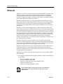
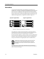
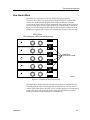
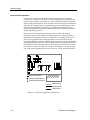
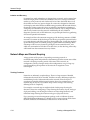
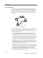
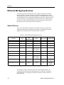
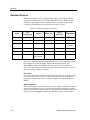
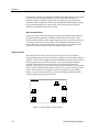
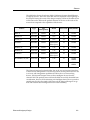
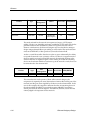
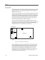
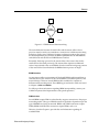
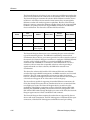
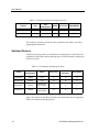
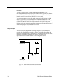
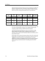
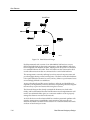
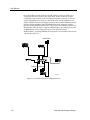
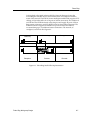
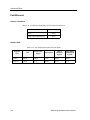
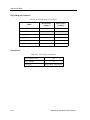
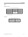
Ethernet through an interconnect cable and have a stack providing 36 ports. This entire stack will act as a single repeater, and the management functions that are included in the SEHI-24 will be applied also to the SEH-22 in the stack. Type Max Management Media Port Count PIMs/BRIMs SEHI-24/34 stack base SNMP UTP 24 2 EPIMs SEH-22/32 stackable NONE UTP 12 1 EPIM Product Loading Dock Shipping 1 Inventory Control 1 Shipping 2 (future) Office Stations (21) Warehouse SEH-24 SEHI-24 Servers (3) Inventory Control 2 2094n16 Business Office Figure 6-4. Ethernet Small Office Implementation The Remote Office The remote office installation is a special case of the small office scenario treated in the previous section. The differentiation between the small office and the remote office is that the remote office requires a connection to a different networking technology in order to make a connection to a larger or physically separate network. In the classical sense, this refers to a branch office location that has a Wide Area Networking link to the parent company network. The vast majority of “remote offices” are actually individual workgroups in a larger facility that are all connected to one another through a high-speed backbone technology such as FDDI. 6-16 Ethernet Workgroup Design Ethernet FDDI Backbone 2094n17 Figure 6-5. FDDI Backbone Internetworking The main difference between the small office and the remote office is that a provision must be made to accommodate a connection to a different networking technology. In the case of Cabletron Systems workgroup products, this process has been simplified by the inclusion of BRIM capabilities into the MicroMMAC stackable bases and the ESX and NBR Ethernet switches. Essentially, the design process for the remote office is the same as that for the small office as discussed previously. The remote office requires an additional series of steps related to the use of BRIMs. Once the localized workgroup portions of the network have been finalized, the BRIM selection process can begin. BRIM Selection As most remote office environments will deal with BRIM-capable standalone or stackable devices, the selection of the correct BRIM is an essential portion of the network design. There are several BRIM models available for a number of different internetworking needs. These BRIM types are listed in Table 4-2, found in Chapter 4, PIMs and BRIMs. For fully up-to-date information regarding BRIM interoperability, contact your Cabletron Systems Sales Representative with specific questions. PIM Selection Several BRIMs require PIMs in order that they support connections to the proper networking media. The type of PIM that must be specified is dependent upon the type of BRIM that is being customized. BRIMs with FDDI connections require FPIMs, BRIMs with Ethernet connections require EPIMs, and so on. Table 4-1, found in Chapter 4, provides the vital information regarding all available PIMs. Ethernet Workgroup Design 6-17 Ethernet Design Example For an example of remote office workgroup configuration, we will build upon the previous small office example. Let us assume that there has been no growth of the small office network, but the pottery distributor has been purchased by a larger, nationwide chain of distributors. The facility itself will not be changing appreciably, but the facility will need a Wide Area Network connection to the regional headquarters in a neighboring state. The regional office makes connections to the remote distributors with 56K WAN links in order to keep running, constantly-updated inventory and accounting records. When comparing the available methods of connecting to the WAN, the Network Designer determines that a Cabletron Systems BRIM, the BRIM-W6, is capable of handling 56K WAN traffic. The networking hardware is still handling network traffic in the facility properly, so there is no need to upgrade the network itself, but the SEHI-24 that is the base of the stack will not support a BRIM. Looking back at the selection chart, the Network Designer notices that the MicroMMAC-24E, another device that can act as a stackable base, supports one BRIM connection. In order to be certain that the network that is being considered will work, the Network Designer consults the table of BRIM interoperability and determines that the BRIM-W6 will, in fact, work properly in the MicroMMAC-24E. The new design requires the replacement of the SEHI-24 with a MicroMMAC-24E containing a BRIM-W6. The stackable hub previously controlled by the SEHI-24 will remain, and will be connected to the MicroMMAC-24E through the HubStack Interconnect Cables. NOTE Intelligent stackable devices cannot be placed in a stack with other intelligent stackable devices. The intelligent devices do not have IN ports for HubStack Interconnect cables. The SEHI-24 can then be placed in storage, ready to be swapped in should there be a problem with the MicroMMAC that requires it be sent back to Cabletron Systems for service. This arrangement of on-site spares can greatly reduce the amount of downtime, or non-operation, that a network experiences. The BRIM-W6 in the MicroMMAC-24E requires further configuration to work with the 56K link. The BRIM-W6, in order to provide the greatest flexibility to consumers, uses specialized PIMs for connection to different WAN types. These Wide Area Network Port Interface Modules, or WPIMs, are listed in the PIMs table, Table 4-1. Examining the table to see which WPIM matches the needs of the facility, the Network Designer chooses the WPIM-DDS. The resulting network now looks like Figure 6-6. 6-18 Ethernet Workgroup Design Ethernet Office Stations (21) To Main Office SEH-24 MicroMMAC-24 with BRIM-W6 Servers (3) Business Office WAN (56K) 2094n18 Figure 6-6. Ethernet Remote Office Implementation The High-End Department The high-end department is a workgroup with specialized needs, demanding high reliability or high throughput to each and every station. The high-end department typically consists of the most demanding users on the network, and connections between them must be fast, reliable, and predictable. One of the ways to supply predictability and speed to users in the high-end workgroup is through per-port switching. In a switched Ethernet workgroup, an Ethernet switch provides dedicated 10 Mbps Ethernet links to each and every user. This means that there will always be an available, full-speed Ethernet link that may be set up between any two Ethernet stations in the high-end workgroup. The use of switched connections in an Ethernet environment provides an added benefit to stations requiring high throughput. Since each Ethernet link is dedicated, and will receive traffic from no other sources than the station and the switch, if the network is within the allotted limitations, the Ethernet link can operate in full-duplex mode. This method of operation allows a station or switch to transmit data on one portion of the Ethernet link while simultaneously receiving data on the other portion of the link. This concurrent transmission and reception effectively doubles the throughput of the Ethernet link, from 10 to 20 Mbps. Abstracting the Design Process The design of a high-end department’s workgroup solution is a highly customized procedure. The organization of the workgroup determines the distribution and provision of switched ports and switched uplinks. The decisions to be made are similar to those dealt with in other design strategies, but the demanding nature of the high-end department tends to influence the decisions toward greater control and higher functionality. Ethernet Workgroup Design 6-19 Ethernet Management In a network using any form of segmentation, whether it is bridging, switching, or routing, management functionality is a part of the devices needed to create the network. Without some form of management, segmentation decisions can not be made by the devices. The level of management available in any segmentation situation is the differentiation between products. Again, the decision of what level of management functionality a particular installation requires is a matter for the Network Designer to decide on an individual basis. Expandability Switches are not noted for their fluid expansion path. It is not possible to add switches to another switch in order to make a stack. Any time a high-end workgroup needs to expand, it will have to make a switched connection between switches. Often this is accomplished with a simple jumper cable, from a front panel port of one switch to a front panel port of another. In these situations, it is important to remember that Ethernet treats switches like bridges, and imposes a bridge rule upon any Ethernet network: no more than eight segments and seven bridges in the longest signal path. Since this bridge rule can severely limit the magnitude of networks incorporating per-port switching on a large scale, the expansion of high-end workgroups is often accomplished through the interconnection of several switches through a faster, larger-scale networking technology. Interconnection As mentioned above, many times the interconnection of switches for a high-end department will be accomplished through the use of a higher-speed technology, such as FDDI. In these situations, the BRIM support of some Cabletron Systems standalone switching products can be very useful, saving the Network Designer the cost of a separate standalone Ethernet to FDDI bridge or router. Port Count The examination of port count, as before, is a simple comparison of requirements to availability. If a device does not meet the port count requirements of the workgroup, additional devices may have to be added to the design. Price As switches incorporate additional decision-making logic and memory for the performance of their functions, switches, as a rule, are more expensive than simple repeaters. The per-port cost may be greater than that of a stackable hub, but the functionality provided by each port is also much greater. When designing a high-end workgroup, keep the price levels that will be involved in mind. 6-20 Ethernet Workgroup Design Ethernet Design Example As an example, we can examine a network design that is being planned for a group of Computer-Aided Design (CAD) engineers in a large architectural firm. These CAD designers want to replace their existing shared Ethernet LAN with a network that provides greater throughput between their end stations. The Network Designer, who is already familiar with Ethernet networking, does not wish to change the technology that the group uses, and has decided that a simple and cost-effective way to provide more bandwidth to each end station is through per-port switched Ethernet connections. The CAD department consists of 16 CAD designers, 2 CAD image file servers, and 3 plotters, all in a single facility. The stations have existing 10BASE-T links to the wiring closet. The CAD department is currently linked to the rest of the company through an Ethernet connection to a bridge in the Materials Research department. The Network Designer, hoping to simplify the network, wants to connect the CAD group directly to the corporate backbone, an FDDI ring. Materials Research CAD Stations (16) Plotters (3) repeater Image Servers (2) repeater bridge FDDI Backbone 2094n19 Figure 6-7. High-End Department - Initial Scenario Ethernet Workgroup Design 6-21 Ethernet The Network Designer is looking for one or more per-port Ethernet switches that can be used to make network connections to the stations in the CAD department. The Network Designer examines the selection field of Ethernet switches, shown in Table 6-2. All of these devices meet the initial criteria; they are manageable Ethernet switches with similar expansion capabilities. Because of the Network Designer’s intent to connect the Ethernet switches directly to the corporate FDDI backbone, the products that do not support BRIM connections are eliminated from consideration. This leaves the selection field shown below. Max Management Media Port Count Switch Interfaces NBR-620 SNMP – 0 6 4 EPIMs 2 BRIMs ESX-1320 RMON UTP 12 13 1 BRIM ESX-1380 RMON Multimode Fiber Optics 12 13 1 BRIM Name PIMs/BRIMs The Network Designer then moves on to examining the port count and media type of the remaining devices. The NBR-620 is immediately removed from consideration due to the low port count it provides. In order to meet the needs of the network, the Network Designer would have to configure 6 NBR-620 Ethernet switches, each of which would have to contain four EPIMs for 10BASE-T connections and one BRIM for a connection to the FDDI backbone. As such a solution would cost more than comparable solutions, without providing a significant benefit over those solutions, the NBR-620 is removed from consideration. This leaves the selection field with the ESX-1320 and ESX-1380, two Ethernet switches that support RMON management, one BRIM connection, and 12 switch interfaces. The port count requirements are not met by either device alone, however. The Network Designer refers back to the full selection field, looking for a device that will support all 21 of the stations in the workgroup. The device that is capable of supporting 24 switched Ethernet connections, the FN10, has already been removed from consideration, but it is re-introduced due to its higher port count. The Network Designer takes a second look at the capabilities of the FN10 in comparison to those of the ESX-1320 and ESX-1380. Deciding that the BRIM capability and advanced network management of the ESX-1320 and ESX-1380 outweigh the higher port count of the FN10, the Network Designer again removes it from consideration and continues. The Network Designer than examines the media that are supported by the two devices still under examination. The ESX-1380 supports 12 multimode fiber optic connections, while the ESX-1320 supports unshielded twisted pair cabling. 6-22 Ethernet Workgroup Design Ethernet The Network Designer selects the ESX-1320 and calculates that two ESX-1320 switches, each containing one BRIM module for an FDDI connection, will meet the needs of the CAD department. The Network Designer would then go on to select the correct BRIMs and any necessary PIMs for these switches. Referring to the BRIM chart, the Network Designer finds that the BRIM-F6 is the BRIM that is needed. This FDDI BRIM requires two FDDI Port Interface Modules, or FPIMs. Matching the media type of the corporate backbone to the media types of the FPIMs, the Network Designer selects four FPIM-00 modules, two for each BRIM. The resulting network, when installed, will resemble that shown in Figure 6-8, below. Materials Research CAD Stations (16) Plotters (3) ESX-1320 containing BRIM-F6 repeater Image Servers (2) bridge 2094n20 FDDI Backbone Figure 6-8. Ethernet High-End Department Implementation Ethernet Workgroup Design 6-23 Ethernet Permutations It is also possible to use an Ethernet switch to connect a series of individual workgroups, rather than workstations or other devices. In these situations, the Ethernet switch acts as a device collapsed backbone for the network. The design process is exactly the same as that used to connect multiple workstations over an Ethernet switch, but the connections are made to workgroups rather than individual stations. Design Example Our example situation for the interconnection of workgroups through a standalone Ethernet switch involves a planned device collapsed backbone. This backbone will be implemented in a small vocational college which plans to interconnect its Ethernet classrooms and laboratories. The classrooms and labs are configured with Ethernet stackable hubs. There are four classrooms and two labs to be connected to the backbone, and there is expected to be growth in the number of Ethernet workgroups at the college in the future. The connections from the classrooms to the switch (which will be located in one of the labs) will have to be made through an aerial cable between buildings. Since conductive cable run between buildings is a lightning hazard, multimode fiber optics will be used to connect to each stack. The Network Designer examines the available Ethernet switches for a product with sufficient management, port count, media, and interface characteristics. The only Ethernet switch in the selection field that provides native multimode fiber optic media support is the ESX-1380, which provides sufficient numbers of ports and the availability of a BRIM port for future migration to new networking technologies. The Network Designer plans on using the ESX-1380 and orders six EPIM-F2s which will provide multimode fiber optic connections at each of the six remote workgroups. 6-24 Ethernet Workgroup Design Chapter 7 Fast Ethernet This chapter examines the decisions and selections that must be made when designing a Fast Ethernet workgroup solution. Should a Fast Ethernet workgroup solution be selected, the Network Designer has a specific series of issues to resolve and decisions to make before selecting a Fast Ethernet device that meets the requirements of the network. This chapter identifies and discusses these issues and provides a series of examples for different Fast Ethernet network approaches. Fast Ethernet Workgroup Devices The following sections present and describe the various Cabletron Systems workgroup networking devices that may be used to implement a Fast Ethernet networking solution. Shared Devices The selection field of Fast Ethernet networking devices is much narrower than that available for Ethernet workgroups. The Fast Ethernet devices available from Cabletron Systems are all 100BASE-TX compliant Class I repeaters or switches. The currently-available Class I repeaters, which are shared Fast Ethernet devices, are listed in Table 7-1, below. 7-1 Fast Ethernet Table 7-1. Shared Fast Ethernet Workgroup Devices Type Max Management Media Port Count PIMs/BRIMs SEH100TX-22 stackable NONEa UTP 22 1 EPIM SEHI100TX-22 stack base SNMP UTP 22 2 EPIMs Product a. These products can be managed through the addition of an intelligent stackable device to their stack. The columns in the table provide the same information that Table 6-1 provides regarding Ethernet devices. Switched Devices Cabletron Systems produces one Fast Ethernet switching device, the FN100. The capabilities of the FN100, and the differing types of FN100 available are displayed in Table 7-2, below. Table 7-2. Fast Ethernet Workgroup Switches Max Management Media Port Count Switch Interfaces PIMs/BRIMs FN100-8TX SNMP UTP 8 8 0 FN100-16TX SNMP UTP 16 16 0 FN100-8FX SNMP Multimode Fiber Optics 8 8 0 FN100-16FX SNMP Multimode Fiber Optics 16 16 0 Name Again, the columns of the table provide the same information that is supplied by Table 6-2 for Ethernet switching devices. 7-2 Fast Ethernet Workgroup Devices Fast Ethernet Fast Ethernet Workgroup Design The network design process for Fast Ethernet workgroups is nearly identical to that used for standard Ethernet workgroups. The Network Designer must first break the network up into workgroups, if desired, determine how the stations in each workgroup will relate to one another, and then begin the process of selecting hardware. The types of hardware considered will be dependent upon the type of network installation that the workgroup is being designed for. The following sections break the process of Fast Ethernet network design up into treatments of three different types of situations: those requiring a relatively large number of users (the small office), those requiring high per-port throughput (the high-end department), and those situations where several workgroups are being interconnected (Fast Ethernet as a backbone). While these situations do not cover every possible Fast Ethernet implementation, it is a relatively simple task to use the closest approach to the particular needs of the proposed workgroup as a template for design. Small Offices The term “small office” as it applies to Fast Ethernet installations using Cabletron Systems workgroup devices, can be misleading. This workgroup archetype simply refers to the workgroup as a single segment with no special internetworking needs (no uplinks to different WAN or backbone technologies). The small office, in the case of the design strategy outlined below, can include anywhere from two to 120 Fast Ethernet stations. Abstracting the Design Process As the number of potential devices to select from in a Fast Ethernet network design is quite small, the actual design process for workgroup networks is highly simplified. The Network Designer needs only to determine what level of management is required within the workgroup and calculate the number of ports that will be needed to support the users at that location. Management Requirements As there are only two choices for shared segment Fast Ethernet devices, the selection of management functionality becomes a “yes or no” decision. The control and troubleshooting ease supplied by management capabilities is often of greater value in the complex and high-performance Fast Ethernet networks than the cost reduction realized by foregoing management altogether. Fast Ethernet Workgroup Design 7-3 Fast Ethernet Port Count The first device in the stack, whether an intelligent SEHI100TX-22 or non-intelligent SEH100TX-22, will provide connections for up to 22 Fast Ethernet stations. For every additional 22 Fast Ethernet stations or fraction thereof, the Network Designer must add one SEH100TX-22 to the stack. The maximum number of ports that can be supported in this fashion is 110. In order to support more connections, the user-configurable EPIM slots on the SEHI100TX-22 and SEH100TX-22 will have to be used. If the EPIM slots are all used, the Fast Ethernet stack will reach its limitation of 119 users. Any Fast Ethernet workgroup containing more than 119 stations will require the creation of another workgroup to support the full user count. Design Example A travel agency sales department is looking to replace its current Ethernet network with a Fast Ethernet network in order to gain higher throughput and faster access to shared resources such as the two departmental file servers and the order entry system. The department also plans to add twenty sales representatives to the current network in the coming fiscal quarter. Order Entry Servers (2) repeater repeater Stations (40) 2094n21 Figure 7-1. Small Office Network - Current Status 7-4 Fast Ethernet Workgroup Design Fast Ethernet The current network consists of 43 stations, including the shared servers and order entry system. The department currently operates on two standalone 24-port Ethernet repeaters that are connected to one another with a single jumper cable. All stations in the network are connected to these standalone repeaters with Category 5 UTP cable. All of the distances and network radii have been calculated to be within the acceptable limits for a Fast Ethernet network using a Class I repeater. The Network Designer, looking over the available Fast Ethernet networking devices, has only a few decisions to make to select a product or series of products for the installation. The Network Designer decides not to pursue a switched Fast Ethernet network implementation, due to the perceived higher cost of such a solution. The Network Designer then turns to the question of management. Understanding the value of management functions to a network of this scale and complexity, the Network Designer intends to incorporate management into the workgroup to aid in diagnosing problems and controlling the network. Examining the selection filed, the Network Designer selects the SEHI100TX-22, which provides SNMP management functions. As the SEHI100TX-22 is a stack base, any non-intelligent SEH100TX-22 hubs that are connected to the SEHI100TX-22 with HubSTACK Interconnect Cables will also become a manageable device. As it has already been established that the proposed network plans to add not less than 20 users in the upcoming quarter, it stands to reason that the network will expand even more in the future. This expansion can be managed quite easily by the SEHI100TX-22 stackable base. Any time that the number of station connections required by the network exceeds that provided by the Fast Ethernet stack, an additional SEH100TX-22 non-intelligent stackable hub can be added to the stack, providing an additional 22 ports. The Network Designer then double-checks the available port count of the SEHI100TX-22. While the SEHI100TX-22 can support only 22 of the 43 required connections, the device is designed to act as a stack base. By adding one SEH100TX-22 to the stack, the Network Designer expands the port capacity of this Fast Ethernet repeater domain to 44 users. When the next 20 users are added in the upcoming fiscal quarter, another SEH100TX-22 can be placed in the stack, bringing the total number of ports supported up to 66. Fast Ethernet Workgroup Design 7-5 Fast Ethernet This expansion can continue until the stack contains five devices, the maximum number allowable with the stackable hub design. At this limitation, the stack will be capable of supporting up to 110 Fast Ethernet users. The network, as designed, will look like the depiction shown in Figure 7-2. Order Entry Servers (2) (future) TX SEH100TX-22 TX Stations (40) SEHI100TX-22 2094n22 Figure 7-2. Fast Ethernet Small Office Implementation High-End Department As previously seen in the design approach to small office implementations of Fast Ethernet, the design approach and decisions required of high-end departments using the Fast Ethernet technology do not differ much from those used for normal Ethernet designs. In the same fashion, the definition of a Fast Ethernet high-end department is identical to that of a standard Ethernet high-end department. The high-end department is a workgroup that has a number of closely associated stations or users, each having very demanding network needs. These stations often require the special functions provided by switching: dedicated links, high throughput, and full-duplex operation. 7-6 Fast Ethernet Workgroup Design Fast Ethernet Abstracting the Design Process As the Fast Ethernet switch selection field, shown in Table 7-2, contains only one device, the amount of decision-making remaining in the design process after the decision to use the Fast Ethernet technology is minimal. Due to the fact that the FN100-TX series is available with either eight or 16 switch interfaces and front panel ports that use either UTP or multimode fiber optic media, there are a few design issues left where decisions have to be made. Media To date, there are two media options available for Fast Ethernet networks: UTP and multimode fiber optics. The selection of a particular media for a Fast Ethernet network implementation must be accomplished before any hardware selection has been done. This is so the network radius and segment length calculations may be made and checked against the allowable maximums of the Fast Ethernet technology. Port Count As Fast Ethernet switches are not as easily expanded to accommodate new connections as stackable hubs are, it may be wise when designing a Fast Ethernet workgroup to provide extra connections. This kind of forethought can save the cost of purchasing another standalone device to provide network access to just one more station in the future. Design Example As an example of a high-end department implementing a Fast Ethernet network solution, let us examine a university mathematics lab consisting of 14 high-performance workstations which handle complex calculations and perform a variety of networked applications, including imaging, estimation, and series sorting. All of these stations are to be configured to connect to the Fast Ethernet network using Category 5 UTP cabling. All of the stations in the laboratory have been determined to lie well within the maximum network radius of a Fast Ethernet network. The Network Designer plans to use switched Fast Ethernet as a networking technology, and intends to connect this workgroup to the campus network through a fiber optic Fast Ethernet connection to the facility hub, which handles all connections to the campus backbone network. Fast Ethernet Workgroup Design 7-7 Fast Ethernet The Network Designer begins the design process by examining the available Fast Ethernet switch products. As the only devices available offering per-port Fast Ethernet switching are the four types of FN100 standalone switch, the selection field is very narrow, consisting of the products shown in the table below. Max Management Media Port Count Switch Interfaces PIMs/BRIMs FN100-8TX SNMP UTP 8 8 0 FN100-16TX SNMP UTP 16 16 0 FN100-8FX SNMP Multimode Fiber Optics 8 8 0 FN100-16FX SNMP Multimode Fiber Optics 16 16 0 Name Due to the extremely limited selection field, the Network Designer can only select one of the two FN100 models or attempt to use a different solution for this workgroup, perhaps selecting a modular chassis-based solution. The FN100-16TX meets the required port count of 14. As there are no other options available from which to choose a compliant device for this network implementation, the Network Designer examines the Cabletron Systems Networking Solutions Product Guide to determine the fitness of the FN100-16TX for this particular situation. Examining the Cabletron Systems Networking Solutions Product Guide, the Network Designer discovers that the FN100-16TX, which had been selected, provides two 100BASE-FX connections that may be activated in the place of two of the 100BASE-TX connections. By disabling one of the UTP connections, the Network Designer can make the desired multimode fiber optic link to the facility hub without requiring an external transceiver. The resulting network looks like Figure 7-3. 7-8 Fast Ethernet Workgroup Design Fast Ethernet Stations (14) Facility Hub FN100-16TX 2094n23 Figure 7-3. Fast Ethernet High-End Department Solution Fast Ethernet as a Backbone Due to the high throughput provided by Fast Ethernet, it is conceivable that the technology could be used as a backbone solution to interconnect a series of workgroups. The Fast Ethernet switch will act as a device collapsed backbone for the network. The design process is exactly the same as that depicted above, in which connections were designed between multiple workstations over a Fast Ethernet switch, but the connections in the backbone solution are made to workgroups rather than individual stations. NOTE Due to the short maximum distances of Fast Ethernet segments, Fast Ethernet is sometimes unsuitable for interconnecting workgroups in a widely-dispersed enterprise network. Design Example As an example of the methods used to design a switched Fast Ethernet backbone network, let us examine the design process of a Network Designer at a small magazine publishing house who intended to replace the existing Ethernet backbone (shared thick coaxial cable) in the facility depicted in Figure 7-4 with a device collapsed backbone using switched Fast Ethernet. Fast Ethernet Workgroup Design 7-9 Fast Ethernet StockPhoto Archive1 Archive2 2094n24 Figure 7-4. Initial Network Design Each departmental stack consists of one MicroMMAC-24E and one or more SEH-24 stackable hubs. In the initial configuration, the MicroMMAC-24Es have been configured with EPIM-A modules, which provide AUI ports for connection to a standard Ethernet AUI cable. These AUI cables are then connected to thick coaxial cable transceivers that are connected to the coaxial cable backbone. This arrangement is currently suffering from slow network response times and poor throughput during normal working hours. The thick coaxial cable backbone is also quite difficult to monitor for errors, and any failures or performance losses are exceedingly difficult to troubleshoot. Access to the three shared file servers (Archive1, Archive2, and StockPhoto) is required by all departments, and users have been complaining about the length of time necessary to place and retrieve files using these servers. The Network Designer has already examined the distances involved in the facility, and has determined that the Fast Ethernet network implementation will need to use multimode fiber optics as a connection media in order to properly manage the distances involved in the network. As all of the devices in the selection field have similar operational qualities with regard to management, expandability, interconnection, and price, the only decisions that need to be made for the selection of a central Fast Ethernet switch are those of media and port count. 7-10 Fast Ethernet Workgroup Design Fast Ethernet The Network Designer examines the four types of FN100 Fast Ethernet switch, looking to see which models support front panel multimode fiber optic connections. The FN100-8FX and FN100-16FX both provide multimode fiber optic connections for 100BASE-FX network media, and thus both meet the requirements of this site. The Network Designer then examines the port count supported by each device, and finds that both devices will fill the required network link count of six. The Network Designer decides, however, to optimize the access of the workgroups to the three shared fileservers by giving each fileserver a dedicated link to the backbone switch, similar to the depiction in Figure 7-5. switch Servers (100 Mbps) 2094n25 Workgroups (10 Mbps) Figure 7-5. Shared Server Optimizations These switched station connections will provide full Fast Ethernet speed connections to each of the fileservers. While this will introduce a switch into the path from any station to any server, this will offer better throughput from a network-wide point of view than leaving the servers on their current shared segments. As no end user station can access the network at a speed greater than the 10 Mbps provided by the shared Ethernet segments, each fileserver can theoretically handle requests from all six workgroups simultaneously without suffering a reduction in throughput to the Fast Ethernet switch. This optimization of the shared resources of the fileservers will cause the required number of connections to exceed the number supplied by the FN100-8FX. The network implementation, therefore, will require the FN100-16FX, which provides 16 multimode fiber optic connections. Fast Ethernet Workgroup Design 7-11 Fast Ethernet Once the backbone switch has been selected, changes need to be made to the workgroups that will connect to the switch itself. As they stand, the current workgroups cannot connect to the Fast Ethernet backbone network. In order to support Fast Ethernet connections to the FN100-16FX, the MicroMMACs will require a BRIM. The Network Designer examines the available BRIMs that can be placed in the MicroMMAC-24Es. The BRIM-E100, when configured with the proper Fast Ethernet Interface Modules, will provide a Fast Ethernet uplink to the MicroMMAC-24Es. In order to support multimode fiber optic cabling, each of the six BRIM-E100s will be configured with two Fast Ethernet Interface Module-100FXs, providing 100BASE-FX connections. Once installed, the network will look like Figure 7-6. StockPhoto FN100-16FX Archive1 Archive2 2094n26 Figure 7-6. Fast Ethernet Backbone Implementation 7-12 Fast Ethernet Workgroup Design Chapter 8 Token Ring This chapter examines the decisions and selections that must be made when designing a Token Ring workgroup solution. The process of designing a Token Ring workgroup or a series of interconnected workgroups is somewhat different from the processes involved in designing an Ethernet or Fast Ethernet workgroup. The Token Ring networking technology places very strict limitations on several aspects of network design, and treats individual stations in a different manner than the other technologies treated in this document. Token Ring Workgroup Devices The following sections present and describe the various Cabletron Systems workgroup networking devices that may be used to implement a Token Ring networking solution. Shared Devices The vast majority of Token Ring networking devices available from Cabletron Systems are differing types of concentrators. The distinctions between the available devices are more differences of magnitude rather than of presence. While almost all the Token Ring devices that Cabletron Systems manufactures have some management capabilities, the Network Designer can choose the level of management incorporated on the devices. 8-1 Token Ring The available devices and the main distinctions between them are summarized in Table 8-1. Table 8-1. Token Ring Workgroup Devices Type Max Management Media Port Count PIMs/BRIMs STH-22/24 stackable NONEa UTP 12/24 2 TPIM STH-42/44 stackable NONEa STP 12/24 2 TPIM STHI-22/24 stack base SNMP UTP 12/24 2 TPIM STHI-42/44 stack base SNMP STP 12/24 2 TPIM MicroMMAC-22T/24T stack base RMON UTP 12/24 2 TPIM 1 BRIM MicroMMAC-42T/44T stack base RMON STP 12/24 2 TPIM 1 BRIM Product a. These products can be managed through the addition of an intelligent stackable device to their stack. The columns in the table provide the same information that Table 6-1 provides regarding Ethernet devices. The Port Count field, again, is independent of the PIMs/BRIMs field. 8-2 Token Ring Workgroup Devices Token Ring Token Ring Workgroup Design Once a Network Designer understands the fundamentals of Token Ring design, as described in the Cabletron Systems Networking Guide - MMAC-FNB Solutions, the design of a Token Ring workgroup using standalone and stackable products is quite simple. If the limitations imposed by the standard are not exceeded, the Network Manager needs only to supply the required port count and management functionality, allowing room for future expansion and ensuring sufficient connections for any ring extensions or special media links. Small Office A small office design for a Token Ring network using standalone or stackable devices has two main defining characteristics. A small office Token Ring connects a number of users within one facility or campus that have no special internetworking needs or exceptional performance requirements. Small office Token Ring networks also must have an expected station count within the maximum number allowed on a single Token Ring at the desired network speed and using the intended media. Chapter 2, Review of Networking, provides a table summarizing these maximums. Abstracting the Design Process The procedures and decisions involved in designing a Token Ring network are quite straightforward and simple. Once it has been established that all the station cabling is within the allotted distances and the station count does not exceed the Token Ring maximums, the remainder of the design process is a simple provision of management functionality, sufficient ports, and support for any special connections. Management Requirements The importance of management capabilities in a Token Ring network is an extremely important consideration in the design process. The complexity of a Token Ring network can make unmanaged Token Ring networks extremely difficult to install and set up, and can greatly extend the time needed to troubleshoot network problems without management functions. As management in a well-run network is a paramount concern, Cabletron Systems Token Ring standalone and stackable devices are all manageable devices. The STH series of stackable hubs is one type of Token Ring device that contains no management functionality of its own, but it can be managed by an intelligent stackable base product such as the STHI. The decision to incorporate or forego management, including what level of management is desired, is a decision that must be based on the Network Designer’s level of skill with management and the perceived benefits to be gained from it. Token Ring Workgroup Design 8-3 Token Ring Media It is assumed by this document that the selection of a networking media for the facility has already been completed before the hardware is examined. The media decision in the hardware selection stage of network design is one of ensuring that the selected device or devices will support the cabling media that is either planned or in place. In some cases, a small number of station connections will have to be made using a less common media such as fiber optic cable. For these situations, Cabletron Systems produces a wide variety of media converters, which act as transceivers, allowing a Token Ring link to be made through two dissimilar media. Cabletron Systems also provides Token Ring Port Interface Module, or TPIM slots on all of its standalone and stackable Token Ring networking devices. These TPIM slots can be used as Ring-In/Ring-Out ports for the extension of the Token Ring network (discussed below) or used as individual station connections to devices requiring custom media links. Port Count The provision of a sufficient number of ports is perhaps the easiest and most straightforward portion of the Token Ring network design process. As all of the Cabletron Systems standalone Token Ring networking products are also stackable devices, any time a particular location requires more ports than can be supplied by one device, an STH stackable Token Ring hub can be placed atop it. This new device will provide the same management capabilities as the base device, and a greater number of available ports. This stacking process can be continued until either the maximum number of stations on the ring has been reached, or until a single stack incorporates one stackable base device and four stackable hubs. The limitations of the stackable system will not allow more than five devices to be associated with one another in a single stack. Should the port count supplied by a maximum-size stack not be enough to accommodate the user count of an installation, the network will have to be extended, using Ring-In/Ring-Out ports. Ring Extensions Ring extension allows for the growth of a Token Ring network beyond the limitations of a single stack. The use of Ring-In/Ring-Out (RI/RO) ports allows extended lengths of cabling to be used to connect stacks or standalone devices. NOTE 8-4 RI/RO ports do not provide segmentation functions or create a new Token Ring network. Token Ring Workgroup Design Token Ring This extension of the ring can be used to allow the Token Ring network to connect widely-separated groups of stations in a single ring, or can be used to support greater numbers of users than a single Token Ring stack can accommodate. A Token Ring stack of maximum size will provide for the connection of 120 stations, well below the 250 station maximum of the IEEE 802.5 standard for some cabling types. If a Network Designer faced a situation in which a maximum-size stack had not been able to support all the required connections, the addition of an RI/RO link between the full stack and a new stack would allow the network to support up to another 120 stations. These RI/RO connections for ring extension are made using specialized PIMs called TPIMs, or Token Ring Port Interface Modules. NOTE Management functionality provided by an intelligent stack base is not distributed to non-intelligent devices that are connected to that base through RI/RO ports. Design Example The following example traces the design of a small office network. The network is intended for a newly-formed Health Maintenance Organization (HMO), and consists of a series of related departments, each having nearly equal demands of the network. The Network Designer has examined the needs of the end users and the organization of the stations and facility, and has decided that a single, 16Mbps Token Ring network will offer the necessary performance and reliability to this network. The cabling to be used will be Category 5 UTP cable, and all the cable runs have been determined to be within the limitations of the Token Ring networking technology. The HMO network will consist of 45 stations: 15 office receptionists, 12 doctors’ offices, 3 pharmacy stations, 3 records stations, 8 accounting and billing stations, and 4 management personnel. None of these stations has any particular importance over others from the point of view of the Network Designer, and there is currently no desire to provide internetworking capabilities or segmentation to the network. Examining the first networking device selection criteria, the Network Designer, who is familiar with the use of both SNMP and RMON as diagnostic and fault-aversion tools, opts to investigate the short-term cost savings that would be provided by selecting the STHI series of Token Ring concentrators rather than the MicroMMAC-T series of concentrators. The Network Designer eliminates the non-intelligent devices and those devices which provide management functions more extensive than SNMP. The resulting selection field is summarized below. Token Ring Workgroup Design 8-5 Token Ring Type Max Management Media Port Count PIMs/BRIMs STHI-22/24 stack base SNMP UTP 12/24 2 TPIMs STHI-42/44 stack base SNMP STP 12/24 2 TPIMs Product When examining the Media characteristics of the devices remaining in the selection field, the Network Designer immediately eliminates the STHI-42/44 from consideration. The network being designed will use UTP cabling, which is not directly supported by the STHI-42/44. Product STHI-22/24 Type Max Management Media Port Count PIMs/BRIMs stack base SNMP UTP 12/24 2 TPIMs Examining the port count available from the STHI-22/24 devices, the Network Designer notes that even the STHI-24, which provides 24 station ports, will not meet the required station count of 45. As the STHI-24 supports the use of TPIMs for the creation of RI/RO connections, it would be possible to purchase a second STHI-24 and four TPIMs of a matching media type and connect the two devices through the RI/RO ports. This solution, while ideal in situations where users are widely dispersed or located in separate facilities, forces the Network Designer to purchase another intelligent device, and pay for the management capabilities twice. In this example, the use of the STHI-24’s stackable hub capabilities will provide a significant cost savings. As the STHI-24 is a stack base, up to four STH non-intelligent hubs can be stacked on top of it and receive the STHI-24’s SNMP management functionality. 8-6 Token Ring Workgroup Design Token Ring Looking back at the initial selection field, the Network Designer locates the non-intelligent stackable devices and examines them for compliance with the needs of the network. The STH-22/24 non-intelligent stackable hub supports UTP cabling, and provides either 12 or 24 ports of station connectivity. The addition of an STH-24 to the STHI-24 already in the design would supply 48 ports of Token Ring station connectivity and four RI/RO ports for future links if required. The STHI-24 could also support the addition of up to three more STH devices, accommodating up to 72 additional station connections. The network, as configured, would look like Figure 8-1. Pharmacy Accounting Reception Doctors Management Records 2094n27 Figure 8-1. Token Ring Small Office Implementation Token Ring Workgroup Design 8-7 Token Ring 8-8 Token Ring Workgroup Design Appendix A Charts and Tables This appendix provides a central location for a series of tables that contain useful network design information. Workgroup Design Tables Ethernet Table A-1. Shared Ethernet Workgroup Devices Type Max Management Media Port Count PIMs/BRIMs MR9T-E repeater NONE UTP 8 1 EPIM SEH-22/32 stackable NONEa UTP 12 1 EPIM SEH-24/34 stackable NONEa UTP 24 2 EPIMs SEH-22FL stackable NONEa Multimode Fiber Optics 12 1 EPIM SEHI-22/32 stack base SNMP UTP 12 1 EPIM SEHI-24/34 stack base SNMP UTP 24 2 EPIMs SEHI-22FL stack base SNMP Multimode Fiber Optics 12 1 EPIM MicroMMAC-22/32E stack base RMON UTP 12 1 EPIM 1 BRIM MicroMMAC-24/34E stack base RMON UTP 24 2 EPIMs 1 BRIM Product a. These products can be managed through the addition of an intelligent stackable device to their stack. A-1 Charts and Tables Table A-2. Ethernet Workgroup Switches Max Management Media Port Count Switch Interfaces PIMs/BRIMs NBR-220 SNMP – 0 2 2 EPIMs NBR-420 SNMP – 0 4 4 EPIMs NBR-620 SNMP – 0 6 4 EPIMs 2 BRIMs FN10 SNMP UTP 12/24 12/24 0 ESX-1320 RMON UTP 12 13 1 BRIM ESX-1380 RMON Multimode Fiber Optics 12 13 1 BRIM Name Fast Ethernet Table A-3. Shared Fast Ethernet Workgroup Devices Type Max Management Media Port Count PIMs/BRIMs SEH100TX-22 stackable NONEa UTP 22 1 EPIM SEHI100TX-22 stack base SNMP UTP 22 2 EPIMs Product a. These products can be managed through the addition of an intelligent stackable device to their stack. A-2 Workgroup Design Tables Charts and Tables Table A-4. Fast Ethernet Workgroup Switches Max Management Media Port Count Switch Interfaces PIMs/BRIMs FN100-8TX SNMP UTP 8 8 0 FN100-16TX SNMP UTP 16 16 0 FN100-8FX SNMP Multimode Fiber Optics 8 8 0 FN100-16FX SNMP Multimode Fiber Optics 16 16 0 Name Token Ring Table A-5. Token Ring Workgroup Devices Type Max Management Media Port Count PIMs/BRIMs STH-22/24 stackable NONEa UTP 12/24 2 TPIM STH-42/44 stackable NONEa STP 12/24 2 TPIM STHI-22/24 stack base SNMP UTP 12/24 2 TPIM STHI-42/44 stack base SNMP STP 12/24 2 TPIM MicroMMAC-22T/24T stack base RMON UTP 12/24 2 TPIM MicroMMAC-42T/44T stack base RMON STP 12/24 2 TPIM Product a. These products can be managed through the addition of an intelligent stackable device to their stack. Workgroup Design Tables A-3 Charts and Tables PIMs and BRIMs Table A-6. PIM Reference Table PIM A-4 Technology Media Connector EPIM-A Ethernet AUI DB15 (Male) EPIM-C Ethernet Thin Coaxial RG58 EPIM-F1 Ethernet Multimode Fiber Optics SMA EPIM-F2 Ethernet Multimode Fiber Optics ST EPIM-F3 Ethernet Single Mode Fiber Optics ST EPIM-T Ethernet UTP RJ45 EPIM-X Ethernet AUI DB15 (Female) Fast Ethernet Interface Module-100TX Fast Ethernet UTP RJ45 Fast Ethernet Interface Module-100FX Fast Ethernet Multimode Fiber Optics SC Fast Ethernet Interface Module-100F3 Fast Ethernet Single Mode Fiber Optics SC Fast Ethernet Interface Module-100FMB Fast Ethernet Multimode Fiber Optics SC TPIM-F2 Token Ring Multimode Fiber Optics ST TPIM-F3 Token Ring Single Mode Fiber Optics ST TPIM-T1 Token Ring STP DB-9 TPIM-T2 Token Ring UTP RJ45 TPIM-T4 Token Ring UTP RJ45 Workgroup Design Tables Charts and Tables Table A-6. PIM Reference Table (Continued) PIM Technology Media Connector FPIM-00 FDDI Multimode Fiber Optics FDDI MIC FPIM-01 FDDI Multimode Fiber Optics SC FPIM-02 FDDI UTP RJ45 FPIM-04 FDDI STP RJ45 FPIM-05 FDDI Single Mode Fiber Optics FDDI MIC FPIM-05 FDDI Single Mode Fiber Optics SC APIM-11 ATM (TAXI) Multimode Fiber Optics SC APIM-21 ATM (OC3c) Multimode Fiber Optics SC APIM-22 ATM (OC3c) Single Mode Fiber Optics SC APIM-29 ATM (STS3c) UTP RJ45 APIM-67 ATM (DS3) Thin Coaxial RG58 WPIM-DDS WAN (56K) Custom RJ45 WPIM-DI WAN (Drop & Insert) Custom RJ45 WPIM-E1 WAN (E1) Custom RJ45 WPIM-SY WAN (Synchronous DTE) Custom 26-pin RS530A WPIM-T1 WAN (T1) Custom RJ45 Workgroup Design Tables A-5 Charts and Tables Table A-7. BRIM Reference Table Technology Connector Type Ethernet EPIM Fast Ethernet EPIM BRIM-F6 FDDI FPIM (2) BRIM-A6 ATM APIM BRIM-A6DP ATM APIM (2) BRIM-W6 WAN WPIM BRIM BRIM-E6 BRIM-E100 Table A-8. BRIM Interoperability Table BRIMa MicroMMAC22/24/32/34E NBR-620 BRIM #1 NBR-620 BRIM #2 ESX-1320/1380 BRIM-E6 YES YES NO NO BRIM-E100 NO NO NO YES BRIM-F6 YES YES NO YES BRIM-A6 YES NO NO NO BRIM-A6DP NO NO NO YES BRIM-W6 YES NO NO NO a. This table is subject to change as new BRIM modules and revised firmware are released. A-6 Workgroup Design Tables Charts and Tables Networking Standards and Limitations Ethernet Distance Limitations Table A-9. Ethernet Standard Distance Limitations Media Max Distance Thick Coax 500 m Thin Coax 185 m Standard AUI 50 m Office AUI 16.5 m UTP 100 m Fiber Optics (Multimode) 1000 m Fiber Optics (Single Mode) 1000 m General Rules Table A-10. Ethernet General Rules Max # Stations 1,024 Max Repeater Hops/Path 4 Max # Bridges/Path 7 Topologies Networking Standards and Limitations Bus, Star, Tree, Hybrid A-7 Charts and Tables Fast Ethernet Distance Limitations Table A-11. Fast Ethernet (100BASE-TX/FX) Distance Limitations Media Max Distance UTP 100 m Fiber Optics (Multimode) 412 m Network Radii Table A-12. Fast Ethernet Maximum Network Radii Repeater Class UTP UTP & Fiber Optics Fiber Optics UTP & Buffered Uplink Fiber Optics and Buffered Uplink Class I 200 m 260 m 272 m 500 m 800 m Class II 200 m N/A 320 m N/A N/A A-8 Networking Standards and Limitations Charts and Tables Token Ring Distance Limitations Table A-13. Token Ring Maximums Media STP active passive UTP active passive Fiber Optics Cable Type Circuitry active Max # of Stations 4 Mbps 16 Mbps Max Lobe Length 4 Mbps 16 Mbps IBM Types 1, 2 250 250 300 m 150 m IBM Types 6, 9a 250 136 200 m 100 m IBM Types 1, 2 250 250 200 m 100 m IBM Type 9 250 136 133 m 66 m Category 5 150 150 250 m 120 m Categories 3, 4 150 150 200 m 100 m Category 5 100 100 130 m 85 m Categories 3, 4 100 100 100 m 60 m Multimode 250 250 2000 m 2000 m Single Mode 250 250 2000 m 2000 m a. IBM Type 6 cable is recommended for use as jumper cabling only, and should not be used for facility cabling installations. Networking Standards and Limitations A-9 Charts and Tables Ring-In/Ring-Out Limitations Table A-14. Ring-In/Ring-Out Distances Max Distance (4 Mbps) Max Distance (16 Mbps) 770 m 346 m Category 3/4 200 m 100 m Category 5 250 m 120 m Fiber Optics (Multimode) 2000 m 2000 m Fiber Optics (Single Mode) 2000 m 2000 m Media Shielded Twisted Pair Unshielded Twisted Pair General Rules Table A-15. Token Ring General Rules Max # Stations/Ring Max # Bridges Topologies A-10 260 7 Logical Ring/Physical Star Networking Standards and Limitations Charts and Tables FDDI FDDI Distance Limitations Table A-16. FDDI Distance Limitations Media PMD Standard Max Link Distance Fiber Optics (Multimode) MMF-PMD 2 km Fiber Optics (Single Mode) SMF-PMD 60 km Unshielded Twisted Paira TP-PMD 100 m Shielded Twisted Pairb 100 m a. Category 5 UTP cabling only b. IBM Type 1 STP cabling only General Rules Table A-17. FDDI General Rules Max # Stations/Ring Max Total Ring Length Topologies Networking Standards and Limitations 500 100 km Logical Ring, Tree A-11 Charts and Tables A-12 Networking Standards and Limitations Glossary This glossary provides brief descriptions of some of the recurrent terms in the main text, as well as related terms used in discussions of the relevant networking discussions. These descriptions are not intended to be comprehensive discussions of the subject matter. For further clarification of these terms, you may wish to refer to the treatments of these terms in the main text. Words in the glossary description text listed in boldface type indicate other entries in the glossary which may be referred to for further clarification. 100BASE-FX IEEE standard which details the operating and performance characteristics of fiber optic cabling in Fast Ethernet networks. 100BASE-TX IEEE standard which deals with the use and performance of UTP cabling in Fast Ethernet networks. 10BASE2 IEEE standard which governs the operation of devices connecting to Ethernet thin coaxial cable. 10BASE5 IEEE standard which governs the operation of devices connecting to Ethernet thick coaxial cable. 10BASE-FL IEEE standard which governs the operation of devices connecting to Ethernet fiber optic cable. Supersedes previous FOIRL standard. 10BASE-T IEEE standard which governs the operation of devices connecting to Ethernet Unshielded Twisted Pair (UTP) cable. A/B Ports FDDI ports which provide connection, in pairs, to the dual counter-rotating ring. Application 1: A software operation performed by a workstation or other network node. 2: A layer of the OSI Model. Architecture A collective rule set for the operation of a network. Architectures describe the means by which network devices relate to one another. Architecture types include Mainframe-Terminals, Peer-to-Peer, and Client-Server. ATM Asynchronous Transfer Mode. A networking technology that is based on the use of connections between communicating devices that are set up, used, and then eliminated. Glossary-1 Attenuation to Client-Server Attenuation Loss of signal power (measured in decibels) due to transmission through a cable. Attenuation is dependent on the type, manufacture and installation quality of cabling, and is expressed in units of loss per length, most often dB/m. AUI Attachment Unit Interface. A cabling type used in Ethernet networks, designed to connect network stations and devices to transceivers. Backbone A portion of a network which provides the interconnection of a number of separate, smaller networks. Bit Binary Digit. A bit is the smallest unit of information, consisting of a single binary number. A bit is represented by a numerical value of 1 or 0. BOOTP Bootstrap Protocol. Checks MIB variables of an SNMP manageable device to determine whether it should start up using its existing firmware or boot up from a network server specifically configured for the purpose. Bridge Bridges are network devices which connect two or more separate network segments while allowing traffic to be passed between the separate networks when necessary. Bridges read in packets and decide to either retransmit them or block them based on the destination to which the packets are addressed. BRIM Bridge/Router Interface Module. BRIMs are added to BRIM-capable Cabletron Systems equipment to provide connections to external networks through an integrated bridge or router. Broadcast A type of network transmission; a broadcast transmission is one which is sent to every station on the network, regardless of location, identification, or address. Buffered Uplink A type of Fast Ethernet connection that provides retiming and regeneration of signals. In effect, the buffered uplink provides the distance characteristics of a bridged connection without performing actual segmentation. Client A workstation or node which obtains services from a server device located on the network. Client-Server A computing model which is based on the use of dedicated devices (servers) for the performance of specific computational or networking tasks. These servers are accessed by several clients, workstations which cannot perform those functions to the same extent or with the same efficiency as the servers. Glossary-2 Coaxial to Decryption Coaxial An Ethernet media type which consists of a core of electrically conductive material surrounded by several layers of insulation and shielding. Concentrator A network device which allows multiple network ports in one location to share one physical interface to the network. Congestion An estimation or measure of the utilization of a network, typically expressed as a percentage of theoretical maximum utilization of the network. Connectivity The physical connection of cabling or other media to network devices. The coupling of media to the network. Crossover A length of multi-stranded cable in which the transmit wire(s) of one end is/are crossed over within the cable to connect to the receive wire(s) of the other end. Crossovers are used to connect devices to like devices, ensuring that transmit and receive connections are properly made. Crosstalk A corruption of the electrical signal transmitted through a Shielded or Unshielded Twisted Pair cable. Crosstalk refers to signals on one strand or set of strands affecting signals on another strand or set of strands. CSMA/CD Carrier Sense Multiple Access with Collision Detection. CSMA/CD is the basis for the operation of Ethernet networks. CSMA/CD is the method by which stations monitor the network, determine when to transmit data, and what to do if they sense a collision or other error during that transmission. Data Information, typically in the form of a series of bits, which is intended to be stored, altered, displayed, transmitted, or processed. Data Loop A condition caused by the creation of duplicate paths which network transmissions could follow. Data loops are created by the use of redundant connections between network segments or devices. Ethernet networks cannot effectively function with data loops present. To allow the creation of fault-tolerant networks, data loops are automatically detected and eliminated by the Spanning Tree algorithm. DB15 A 15-pin connector used to terminate transceiver cables in accordance with the AUI specification. DB9 A 9-pin connector, typically used in Token Ring networks and for serial communications between computers. Decryption The translation of data from an encrypted (see encryption) form into a form both recognizable and utilizable by a workstation, node, or network device. Glossary-3 Dedicated to Fault-Tolerance Dedicated Assigned to one purpose or function. Device (network) Any discrete electronic item connected to a network which either transmits and receives information through it, facilitates that transmission and reception, or monitors the operation of the network directly. DLM Distributed LAN Monitor. DLM is a feature of some SNMP management devices which allows that device to locally monitor other devices under its control and report to a central network management station any noted errors. This frees the network management station from directly monitoring every SNMP device. DNI Desktop Network Interface. DNI cards are devices which are added to workstations to provide them with a connection to a network (NIC). Dual Attached Connected to an FDDI dual counter-rotating ring through the use of A/B ports. Dual Homing A station connection method for FDDI which connects a device’s A/B ports to the M ports of two separate dual-attached concentrator devices, providing fault-tolerance. EEPROM Electronic Erasable Programmable Read-Only Memory. Encryption A security process which encodes raw data into a form that cannot be utilized or read without decryption. EPIM Ethernet Port Interface Module. EPIMs are added to specifically-designed slots in Cabletron Systems Ethernet products to provide connections to external media. EPIMs allow a great flexibility in the media used to connect to networks. Ethernet A networking technology which allows any station on the network to transmit at any time, provided it has checked the network for existing traffic, waited for the network to be free, and checked to ensure the transmission did not suffer a collision with another transmission. See also CSMA/CD. Fast Ethernet A networking technology based on the Ethernet technology. Fast Ethernet operates at 10 Mbps, ten times the speed of standard Ethernet networks. Fault-Tolerance The ability of a design (device or network) to operate at full or reduced capacity after suffering a failure of some essential component or connection. See also redundant. Glossary-4 FDDI to Impedance FDDI Fiber Distributed Data Interface. A high-speed networking technology. FDDI requires that stations only transmit data when they have been given permission by the operation of the network, and dictates that stations will receive information at pre-determined intervals. See also Token. Fiber Optics Network media made of thin filaments of glass surrounded by a plastic cladding. Fiber optics transmit and receive information in the form of pulses of light. See multimode and single mode. File A collection of related data. Fileserver A network server device which stores and maintains data files for access and modification by users. Firmware The software instructions which allow a network device to function. Flash EEPROM See EEPROM. FNB Flexible Network Bus. A Cabletron Systems backplane design which enables an FNB-configured chassis to support multiple network technologies simultaneously. Frame A group of bits that form a discrete block of information. Frames contain network control information or data. The size and composition of a frame is determined by the network protocol being used. Frames are typically generated by operations at the Data Link Layer (Layer 2) of the OSI Model. Gateway A device which connects networks with dissimilar network architectures and which operates at the Application Layer of the OSI Model. May also be used to refer to a router. Heartbeat See SQE. Hexadecimal A base 16 numerical system. Digits in hexadecimal run from 0 to 9 and continue from A to F, where F is equivalent to the decimal number 16. Host A device which acts as the source or destination of data on the network. IEEE Institute of Electrical and Electronic Engineers. A standards-making body. IETF Internet Engineering Task Force. A standards-making body. Impedance A measure of the opposition of electrical current or signal flow in a length of cable. Glossary-5 Interface to MAC Address Interface A connection to a network. Unlike a port, an interface is not necessarily an available physical connector accessible through the front panel of a device. Interfaces may be used as backplane connections, or may be found only in the internal operation of a module (All ports are interfaces, but not all interfaces are ports). Internet A world-wide network which provides access through a vast chain of private and public LANs. Interoperability The capacity to function in conjunction with other devices. Used primarily to indicate the ability of different vendors’ networking products to work together cohesively. IP Internet Protocol. IP Address Internet Protocol address. The IP address is associated, by the network manager or network designer, to a specific interface. The availability of IP addresses is controlled by the IANA. ISO International Organization for Standardization. The ISO has developed a standard model on which network operation is based, called the OSI Model. Jitter Degradation of network signals due to a loss of synchronization of the electrical signals. Jitter is often a result of passing a signal through too many repeaters. LAN Local Area Network. LANVIEW A system which relates diagnostic, troubleshooting, and operational information pertaining to network devices through the use of prominently displayed LEDs. LDRAM Local Dynamic Random Access Memory. LED Light Emitting Diode. A simple electronic light, used in networking equipment to provide diagnostic indicators. Also used as a light source for some fiber optic communications equipment. Load An indication of network utilization. M Ports FDDI connectivity ports located on concentrator devices, to which end nodes connect through their S ports. MAC Address Media Access Control address. The MAC address is associated, usually at manufacture, with a specific interface. Glossary-6 MAU to Network Radius MAU Multistation Access Unit. Mbps Megabits Per Second. Mbps indicates the number of groups of 1000 bits of data that are being transmitted through an operating network. Mbps can be roughly assessed as a measure of the operational “speed” of the network. Media Physical cabling or other method of interconnection through which network signals are transmitted and received. MIC Connector 1: Token Ring genderless connector. 2: FDDI fiber optic connector which may be keyed to act as an M or S connector or A/B connector. Micron (µ) A micrometer, one millionth of a meter. MIM Media Interface Module. See also Module. Mission-Critical Vital to the operation of a network, company, or agency. Modular Chassis A device which provides power, cooling, interconnection, and monitoring functions to a series of flexible and centralized modules for the purposes of creating a network or networks. Module A discrete device which is placed in a modular chassis to provide functionality which may include, but is not limited to, bridging, routing, connectivity, and repeating. Modules are easily installed and removed. Also, any device designed to be placed in another device in order to operate. Multichannel A Cabletron Systems Ethernet design which provides three separate network channels (of Ethernet or Token Ring technology) through the backplane of a chassis, allowing for the creation of multiple networks in a single chassis. Multimode A type of fiber optics in which light travels in multiple modes, or wavelengths. Signals in Multimode fiber optics are typically driven by LEDs. Nanometer One billionth of a meter. NAUN Nearest Active Upstream Neighbor. Network Radius The distance between the two stations on a network that are most remote from one another and the cabling and repeater devices between them. Network radius calculations are essential to ensuring the proper operation of a Fast Ethernet network. Glossary-7 Node to Protocol Node Any single end station on a network capable of receiving, processing, and transmitting packets. NVRAM Non-Volatile Random Access Memory. Memory which is protected from elimination during shutdown and between periods of activity, frequently through the use of batteries. Octet A numerical value made up of eight binary places (bits). Octets can represent decimal numbers from zero (0000 0000) to 255 (1111 1111). OSI Model Open Standards Interconnect. A model of the way in which network communications should proceed from the user process to the physical media and back. Out-Of-Band Performed without requiring the operation of the network technology. Most commonly used in reference to local management operations. Packet A discrete collection of bits that form a block of information. Packets are similar to frames. Packets are typically generated at the Network Layer (Layer 3) of the OSI Model, and are encapsulated in frames before being transmitted onto a network media. Passive Not utilizing per-port reclocking and regeneration of the signal which is propagated throughout the device. Commonly applied to Token Ring equipment to distinguish it from active devices. Phantom Current A weak voltage passed by Token Ring end nodes to the MAU to open the relay for that port. Plenum A cabling term which indicates a cable with insulating material that is considered safe to use in return-air plenum spaces (in contrast to PVC insulation) due to its low relative toxicity if ignited. Port A physical connector which is used as an interface to cabling with modular or pinned connectors. Ports are associated with Interfaces. Port Assignment The association, through software management, of specific ports on a network device to specific channels of a backplane. This assignment is done on an individual port basis. Protocol A set of rules governing the flow of information within a communications infrastructure. Protocols control operations such as frame format, timing, and error correction. See also Architecture. Glossary-8 PVC to Server PVC Polyvinyl Chloride. A material commonly used in the fabrication of cable insulation. This term is used to describe a non-plenum rated insulating material. See also Plenum. PVC releases toxic smoke when burned. Redundant Extra or contingent. A redundant system is one that is held in reserve until an occurrence such as a failure of the primary system causes it to be required. Relay An electrical switch which opens and closes in response to the application of voltage or current. Repeater A network device consisting of a receiver and transmitter which is used to regenerate a network signal to increase the distance it may traverse. Ring-In/Ring-Out Token Ring connections which are made between MAUs utilizing two separate physical cables and incorporating an auto-wrap recovery feature. RJ45 A modular connector style used with twisted pair cabling. The RJ45 connector resembles the modern home telephone connector (RJ11). RMIM Repeating Media Interface Module. A term used to indicate a family of Cabletron Systems Ethernet Media Interface Modules (See MIM) which are capable of performing their own repeater functions. Router A router is a device which connects two or more different network segments, but allows information to flow between them when necessary. The router, unlike a bridge, examines the data contained in every packet it receives for more detailed information. Based on this information, the router decides whether to block the packet from the rest of the network or transmit it, and will attempt to send the packet by the most efficient path through the network. S Ports FDDI ports which are used by FDDI stations and end nodes to make single attached connections to FDDI concentrators. SDRAM Shared Dynamic Random Access Memory. Segment A portion of a network which is separated from other networks. A segment may be one portion of a bridged, switched, or routed network. Segments must be capable of operating as their own networks, without requiring the services of other portions of the network. Server A workstation or host device that performs services for other devices (clients) on the network. Glossary-9 SIMM to Switch SIMM Single In-line Memory Module. A collection of Random Access Memory (RAM) microprocessors which are placed on a single, replaceable printed circuit board. These SIMMs may be added to some devices to expand the capacity of certain types of memory. Single Attached Connected to an FDDI network through a single cable which does not provide for auto-wrap functions. Single Mode A type of fiber optics in which light travels in one predefined mode, or wavelength. Signals in single mode fiber optics are typically driven by lasers. The use of lasers and the transmission characteristics of single mode fiber optics allow the media to cover greater distances than multimode fiber optics. SMA Sub-Miniature Assembly. A modular connector and port system used in multimode fiber optic cabling. The SMA connector is threaded, and is screwed into an SMA port. Spanning Tree A mathematical comparison and decision algorithm performed by Ethernet bridges at power-up. Spanning tree detects the presence of data loops and allows the bridges to selectively activate some ports while others remain in a standby condition, avoiding the data loops and providing redundant paths in the event of bridge failures. SQE Signal Quality Error. A self-monitoring test performed by some Ethernet equipment which examines the status of the device at arbitrary and predefined intervals. ST Straight-Tip. A modular connector and port system used with both multimode and single mode fiber optic cabling. The ST connector utilizes an insert and twist-lock mechanism. Station See node. STP Shielded Twisted Pair. Refers to a type of cabling, most commonly used in Token Ring networks, which consists of several strands of cables surrounded by foil shielding, which are twisted together. See also UTP. Straight-Through A length of multi-stranded cable in which the transmit wire(s) of one end is/are passed directly through the cable to the same location on the other end. Straight-through cables are used for most facility cabling. See also crossover. Switch A network device which connects two or more separate network segments and allows traffic to be passed between them when necessary. A switch determines if a packet should be blocked or transmitted based on the destination address contained in that packet. Glossary-10 TCP to UTP TCP Transmission Control Protocol. Terminal A device for displaying information and relaying communications. Terminals do not perform any processing of data, but instead access processing-capable systems and allow users to control that system. Throughput The rate at which discrete quantities of information (typically measured in Mbps) are received by or transmitted through a specific device. Token A particular type of frame which informs a station in the Token Ring and FDDI network technologies that it may transmit data for a specified length of time. Once that time has expired, the station must stop transmitting and pass the token along to the next station in the network. Token Ring A network technology which requires that stations only transmit data when they have been given permission by the reception of a Token, and dictates that stations will receive information at pre-determined intervals and in a definite series. Topology The physical organization of stations and devices into a network. TP-PMD Twisted Pair - Physical Medium Dependent. Transceiver A device which transmits and receives. A transceiver provides the electrical or optical interface to the network media, and may convert signals from one media for use by another. User Any person who utilizes a workstation or node on the network. UTP Unshielded Twisted Pair. A type of network media which consists of a number of individual insulated cable strands which are twisted together in pairs. Glossary-11 UTP to UTP Glossary-12 Index Numerics E 100BASE-FX 2-3 100BASE-TX 2-3 EPIM 4-3 Ethernet 2-2, 6-1 cable lengths 2-2 high-end department 6-19 home office 6-5 remote office 6-16 shared devices 6-2 signal path 2-3 small office 6-11 station count 2-3 switched devices 6-4 Expansion (of networks) 5-15 A Active circuitry 2-6 APIM 4-5 Assistance 1-3 B Backbones collapsed 5-19 definition 5-17 device 5-20 distributed 5-18 Fast Ethernet 7-9 selection 5-21 Bandwidth 2-2 Bridge 3-2 BRIM 3-7, 4-8, 4-8 to 4-10 C Chapter summaries 1-2 Collapsed backbone 5-19 Concentrator 3-2 CSMA/CD 2-2 Customer Support 1-3 D Device backbone 5-20 Distributed backbone 5-18 Document conventions 1-3 Document organization 1-2 F Fast Ethernet 2-3, 7-1 100BASE-FX 2-3 100BASE-TX 2-3 buffered uplink 2-4 cable length 2-4 high-end department 7-6 network radius 2-4 repeater classes 2-3 shared devices 7-1 small office 7-3 station count 2-5 switched devices 7-2 Fast Ethernet Interface Modules 4-3 FPIM 4-4 Frontier 3-6 G Geographical proximity 5-3 Index-1 Index H S Help 1-3 High-end department 6-19, 7-6 Home office 6-5 HubSTACK Interconnect Cables 3-5 Segmentation 5-2 Small office 6-11, 7-3, 8-3 Stackable 3-4 interconnect cable 3-5 internetworking 3-7 management 3-6 Standalone 3-1 management 3-3 I Installation planning 5-11 Interconnect cables 3-5 internetworking 4-8 Introduction 1-1 N Network growth 5-15 layout 5-10 planning 5-10 Network map 5-14 Network radius 2-4 Networking Services 1-3 P PIM 4-1 ATM 4-5 decoding 4-2 Ethernet 4-3 Fast Ethernet 4-3 FDDI 4-4 naming 4-2 table of types 4-6 Token Ring 4-4 Wide Area 4-5 R Redundancy 5-13 Related documents 1-4 Remote office 6-16 Repeater 3-2 Ring-In/Ring-Out 2-6 Index-2 T Technical Support 1-3 Technology selection 5-9 Token Ring 2-5, 8-1 active circuitry 2-6 link lengths 2-7 Ring-In/Ring-Out 2-6 shared devices 8-1 small office 8-3 station count 2-8 TPIM 4-4 U Using this Guide 1-1 W Workgroup 5-2 designing 5-3 organization common function 5-6 departmental organization 5-4 geographical proximity 5-3 planning 5-2 technologies 5-9 Workgroups high-end 6-19 high-end department 7-6 home office 6-5 remote office 6-16 small office 6-11, 7-3, 8-3 WPIM 4-5