1
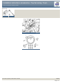
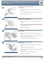
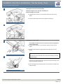
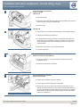
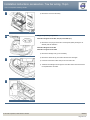
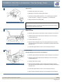
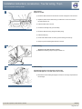
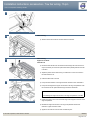
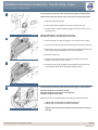
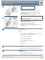
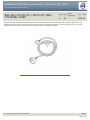
Installation instructions, accessories - Tow bar wiring, 13-pin
Volvo Car Corporation Göteborg, Sweden
S80 (-06) / V70 XC (01-) / XC70 (-07) / S60 /
V70 (00-08) / XC90
Section Group
8
Weight
(Kg/Pounds)
89
Year
Month
2002 06
S60 2001, S60 2002, S60 2003, S60 2004, S80 (-06) 1999, S80 (-06) 2000, S80 (-06) 2001, S80 (-06) 2002, S80 (-06) 2003, S80 (-06) 2004, V70
(00-08) 2000, V70 (00-08) 2001, V70 (00-08) 2002, V70 (00-08) 2003, V70 (00-08) 2004, V70 XC (01-) / XC70 (-07) 2001, V70 XC (01-) / XC70 (07) 2002, V70 XC (01-) / XC70 (-07) 2003, V70 XC (01-) / XC70 (-07) 2004, XC90 2003, XC90 2004
M3702161
© VolvoCar Corporation, 2002 Printed in Sweden
8698535
Page 1 of 17
Installation instructions, accessories - Tow bar wiring, 13-pin
Volvo Car Corporation Göteborg, Sweden
Required tools
A0000162
A0000161
R8802817
M3702108
© VolvoCar Corporation, 2002 Printed in Sweden
8698535
Page 2 of 17
Installation instructions, accessories - Tow bar wiring, 13-pin
Volvo Car Corporation Göteborg, Sweden
Any comments on this publication? Please contact your nearest dealer. Thank you!
Publication no: MA 8698535, Issue: 2002-06
Comments:..........................................................................................................
............................................................................................................................
............................................................................................................................
............................................................................................................................
............................................................................................................................
.............................................................................................................................
From:...................................................................................................................
Address:.............................................................................................................
Telephone no:................................................................................................... .
Telefax:...............................................................................................................
© VolvoCar Corporation, 2002 Printed in Sweden
8698535
Page 3 of 17
Installation instructions, accessories - Tow bar wiring, 13-pin
Volvo Car Corporation Göteborg, Sweden
INTRODUCTION
●
●
NOTE! Read through the entire text before carrying out
any work.
The front page gives the date of this edition and the edition it
replaces
Cars equipped with SRS/SIPS (Airbag)
Warning!
Extra care must be taken when working on cars equipped with SRS/SIPS
air bags. This is important to prevent:
1. Personal injury
The second page shows the tools needed for the installation and
the contents of the installation kit
2. Damage to or malfunction of the SRS/SIPS system.
●
The illustrations display the procedure in order of operation. The
order of operation is repeated in the text section
Work on the SRS/SIPS systems or related components must always be
carried out by an authorised Volvo workshop.
●
Cut out the text page in order to follow the illustrations and text at
the same time.
Is the car equipped with SRS (supplemental restraint system)?
●
Cars equipped with a driver's airbag have the letters "SRS" imprinted on
the centre panel of the steering wheel. Cars equipped with driver's and
passenger airbags are marked with "SRS" on both the steering wheel
centre panel and also on the dashboard close to the airbag.
If the car is equipped with SIPS (side impact protection system ) a "SIPS"
decal is marked on both the front seats.
Cars equipped with inflatable curtains have the marking "SRS" on one of
the panels along the posts on the inside of the car.
Cars equipped with SRS (supplemental restraint system) also have a
"SRS" decal on the front windscreen.
Do not damage the SRS wiring!
Do not trap, fray, pierce or damage the SRS wiring. SRS wiring has
orange casing and/or is plaited.
Steering and front suspension
The contact reel in the SRS system can easily be damaged when
working on the steering wheel, steering shaft or steering gear. Refer to
the SRS (supplemental restraint system) Service Manual or service
instructions in VIDA for information on carrying out such work. This is to
prevent damage.
SRS warning lamp
If the SRS warning lamp lights after repairs have been carried out, take
the car to an authorised Volvo workshop.
SRS collision sensor control module
S60 / V70 (00-) / S80 / XC90
The collision sensor control module is located on the transmission tunnel
© VolvoCar Corporation, 2002 Printed in Sweden
8698535
Page 4 of 17
Installation instructions, accessories - Tow bar wiring, 13-pin
Volvo Car Corporation Göteborg, Sweden
in the centre console, in front of the parking brake.
WARNING!
The air bag inflation areas must not be obstructed. Never place
any objects, such as upholstery or accessories, within these
areas. The panels must be able to deploy in the correct manner
at the right time otherwise there is a risk of personal injury in
the event of a collision.
WARNING!
The ignition must be in position "0" and the key removed from
the ignition if any connector in the SRS system is to be
disassembled. Then wait at least one minute. Then disconnect
the battery negative lead before disassembling any of the
connectors. When work is completed the ignition key must be
turned to position "II" before reconnecting the battery negative
lead.
Tow bar wiring, 13-pin
Note!
The relay and fuses are not included in the kit.
© VolvoCar Corporation, 2002 Printed in Sweden
8698535
Page 5 of 17
Installation instructions, accessories - Tow bar wiring, 13-pin
Volvo Car Corporation Göteborg, Sweden
Installing the connector for detachable tow bars
Applies to the S60
1
●
Install the trailer connector (1). Use the three screws (2) and the nuts (3).
Tighten
●
Route the cable along the underneath of the tow hitch member as illustrated
●
Secure the cable using two tie straps.
M3702248
Installing the connector for detachable tow bars
Applies to the V70 (00-) and V70XC (01-)
2
●
Install the trailer connector (1). Use the three screws (2) and the nuts (3).
Tighten
●
Ensure that the cable harness is as close to the centre mounting on the tow bar
member as possible. This is important to prevent the cable harness from being
caught in the cut-out bumper
●
Secure the cable using a tie strap.
M3702109
Installing the connector for detachable tow bars
Applies to the S80
3
●
Install the trailer connector (1). Use the three screws (2) and the nuts (3).
Tighten
●
Route the cable harness behind the screw (4) on top of the tow bar. Then route
the cable harness down past the bracket (5)
●
Clamp the cable harness at the bracket. Tighten the clamps (6).
D3701464
Installing the connector for fixed tow bars
Applies to the S60
4
M8902146
© VolvoCar Corporation, 2002 Printed in Sweden
●
Install the trailer connector (1). Use the three screws (2) and the nuts (3).
Tighten
●
Leave the bracket hanging down as illustrated
●
Secure the cable harness at the tow hitch member on each side of the tow hitch.
Use a tie strap (4)
●
Position the tie straps according to the listed dimensions
●
Do not tighten the clamps fully yet.
8698535
Page 6 of 17
Installation instructions, accessories - Tow bar wiring, 13-pin
Volvo Car Corporation Göteborg, Sweden
Installing the connector for fixed tow bars
5A
Illustration A applies to the V70 (00-) and V70XC (01-)
Illustration B applies to the S80
●
Install the trailer connector (1). Use the three screws (2) and the nuts (3).
Tighten
●
Clamp the cable harness at the tow bar. Tighten the clamp(s) (4).
M3702110
5B
M3702158
Installing the connector XC90
6A
●
●
On the XC90 the cable harness is routed in the same way regardless
of the tow hitch type
Install the trailer connector (1). Use the three screws (2) and the nuts (3).
Tighten
Route the cable harness to the right along the front edge of the tow hitch
member
Note!
R8903037
6B
●
If the cable harness is stretched too far it may be worn through by the lower
edge of the bumper.
Ensure that the cable harness forms a small loop around the lower edge of the
bumper as illustrated in illustration B
●
Secure the cable harness using a tie strap on each side of the brackets for the
tow hitch member.
R8903038
© VolvoCar Corporation, 2002 Printed in Sweden
8698535
Page 7 of 17
Installation instructions, accessories - Tow bar wiring, 13-pin
Volvo Car Corporation Göteborg, Sweden
Cargo compartment preparations
Applies to the S60
Illustration A
7A
M8901859
7B
●
Fold back the carpet
●
Remove the clips at the bottom edge of the right and left folding panels (press the
centre of the clips until there is an audible click)
●
Remove the clips.
Illustration B
●
Turn the handle (1) on the right and left-hand sides. Turn the handle through 90º.
●
Fold the panels inwards. Lift the panels out
●
Pull the tailgate sill trim panel (2) forwards on the right and left hand sides until
the two clips on each side release. Carefully pull the panel. Use some force as
the panel is tightly secured. Pull the panel straight up until the four clips on the
underside release
●
Remove the wiring (3) for the cargo compartment lighting
●
Lift out the sill trim panel.
M8503264
Cargo compartment preparations
Applies to the V70 (00-) and V70XC (01-)
8
●
Lift up the floor hatch (1). Lift up the storage hatch (2). Remove these two
hatches from the car
●
Remove the side panels (3) on both sides.
M8301410
Cargo compartment preparations
Applies to S60 and S80
9
D8502339
© VolvoCar Corporation, 2002 Printed in Sweden
●
Fold the cargo compartment carpet (1) to one side
●
Turn the clips (2). Fold in the side panels on both sides
●
Remove the two covers (3). Remove the screws (4) underneath the covers.
Grip the outer edges of the panel (5). Pull the panel inwards towards the centre
so that the clips release at the sides. Disconnect the connectors (6) for the side
lamps. Remove the panel by pulling it straight upwards so that the clips release
from the rear crossmember.
8698535
Page 8 of 17
Installation instructions, accessories - Tow bar wiring, 13-pin
Volvo Car Corporation Göteborg, Sweden
Cargo compartment preparations
Applies to the XC90
Illustration A
10A
●
R8902382
10B
Applies to cars with two rows of seats
Fold up the centre rear floor hatch (1)
●
If the floor hatch is equipped with a carrier bag holder, it is secured by a strap on
each of the shorter sides of the storage box. Release the straps and remove the
carrier bag holder
●
Remove the storage box
●
If the fog tail lamp and/or positive power supply / charge function is being
connected, remove the floor hatch completely by folding it almost all the way
down and pulling it out backwards from its mountings.
●
●
R8902766
Applies to cars with three rows of seats and integrated carrier bag
holder on the underside of the centre floor hatch
Fold the rear centre floor hatch up
Detach the two straps from the panel. Lift up the rear edge of the panel. Fold the
floor hatch back towards the panel and lift out the floor hatch and the panel.
●
Applies to cars with three rows of seats without integrated carrier bag
holders
Lift up the centre, rear floor hatch at the rear edge and lift it out.
●
For all CX90
Remove the two side floor hatches (2).
Illustration B
●
Remove the folding side panel on the left and right-hand sides of the cargo
compartment.
Cargo compartment preparations
11A
Illustration A
●
Remove the screw (1), the nuts (2) and then the bracket (3) (pull the bracket
forwards)
●
Lift off the protective cover (4).
Illustration B applies to the XC90
D3100060
© VolvoCar Corporation, 2002 Printed in Sweden
●
Remove the three screws in the battery holder. Lift the battery holder out
8698535
Page 9 of 17
Installation instructions, accessories - Tow bar wiring, 13-pin
Volvo Car Corporation Göteborg, Sweden
11B
●
Remove the cover from the battery.
R3100130
Cargo compartment preparations
12A
Illustration A applies to the S60, V70 (00-) and V70XC (01-)
●
Remove the cover plug from the hole in the bodywork (battery drainage is not
affected). See the illustration.
Illustration B applies to the S80
Illustration C applies to the XC90
●
Remove the drainage hose (1) from the battery
●
Remove the rubber seal (2). The rubber seal will not be used again
●
Pull off the small narrow rubber strap on the new rubber seal
●
Thread the old drainage hose through the new rubber seal. Ensure that the hose
is unimpeded and is not kinked.
M3100077
12B
D3100058
12C
R3100141
© VolvoCar Corporation, 2002 Printed in Sweden
8698535
Page 10 of 17
Installation instructions, accessories - Tow bar wiring, 13-pin
Volvo Car Corporation Göteborg, Sweden
Cable routing
13
M3702159
●
Install the new holder for the connector
●
Release the red catches by pressing them forward
●
Connect the blue (BL) cable to terminals 1, 5 or 12, depending on the desired
function. Terminals: 1 = Charging; 5 = Fog tail lamp; 12 = Reversing lamp
●
Return the catches to the locked position.
Note!
If the "Charging" function is to be used, the existing cable terminal must be cut off and
replaced with the cable terminal from the kit.
Cable routing
Applies to the S60
14
●
Route the cable harness from the tow bar connector through the hole in the floor
●
Adjust the position of the rubber seal (2) so that there is not too much slack in
the cable under the car
●
Install the rubber seal in the hole
●
Route the cable as illustrated. Clamp in the existing cable harness in the sill trim
panel. Ensure that the cable harness is not impeded by the battery holder and the
protective cover
●
Connect the cable harness connector (1) to the existing connector (3).
M3100112
Cable routing
15
Illustration B applies to the V70 (00-) and V70XC (01-)
M3100086
© VolvoCar Corporation, 2002 Printed in Sweden
●
Route the cable harness from the tow bar connector through the hole in the floor
●
Adjust the position of the rubber seal (2) so that there is not too much slack in
the cable under the car
●
Install the rubber seal in the hole
●
Route the cable as illustrated. Clamp the existing cable harness in the sill trim
panel. Ensure that the cable harness is not impeded by the battery holder and the
protective cover
●
Connect the cable harness connector (1) to the existing connector (3)
●
Secure the two connected connectors (4) in the existing hole in the bodywork.
8698535
Page 11 of 17
Installation instructions, accessories - Tow bar wiring, 13-pin
Volvo Car Corporation Göteborg, Sweden
Cable routing
Applies to the S80
16
●
Route the cable harness from the tow bar connector through the hole in the floor
●
Adjust the position of the rubber seal (1) so that there is not too much slack in
the cable under the car
●
Install the rubber seal in the hole
●
Connect the drainage hose (2) to the battery
●
Route the cable harness (3) along the existing wiring
●
Install the clamps (4)
●
Connect the cable harness connector (5) to the existing connector (6)
●
Clamp any excess cable together with the connector.
D3100059
Cable routing
17
●
Applies to cars with two rows of seats
Release the restraining strap for the jack and lift it out.
R8902823
Cable routing
18A
Illustration A applies to cars with two rows of seats
Illustration B applies to cars with three rows of seats
●
Remove the screws holding the support for the floor in the cargo compartment at
the rear edge.
R8903022
© VolvoCar Corporation, 2002 Printed in Sweden
8698535
Page 12 of 17
Installation instructions, accessories - Tow bar wiring, 13-pin
Volvo Car Corporation Göteborg, Sweden
18B
R8903087
Cable routing
19
●
Slacken off the two screws for the floor extension brackets.
R3100168
Cable routing
Applies to the XC90
Illustration A
20A
R3100169
20B
●
Route the cable harness from the tow bar socket through the hole in the floor. It
may be necessary to remove the spare wheel which partially obstructs the hole
in the floor
●
Adjust the position of the rubber seal (1) so that there is not too much slack in
the cable under the car
●
Install the rubber seal in the hole
●
Pull up the floor extension on the right-hand side. Position a shim underneath it
●
Pull up the rear edge of the support for the floor in the cargo compartment. Push
the connector into the space behind the right-hand rear wheel well.
Note!
Do not damage the support for the floor in the cargo compartment. It is brittle.
●
Position the cable in the cut-out at the rear edge of the support for the floor in the
cargo compartment
●
Reinstall the support for the floor in the cargo compartment and the floor
extension. Tighten the three screws
●
Applies to cars with two rows of seats: reinstall the jack.
R3903744
© VolvoCar Corporation, 2002 Printed in Sweden
8698535
Page 13 of 17
Installation instructions, accessories - Tow bar wiring, 13-pin
Volvo Car Corporation Göteborg, Sweden
Illustration B
●
Connect the routed cable harness to the existing pre-routed cable harness in the
space
●
Route the excess cable into the small space and secure to the existing cable
harness. Ensure that the connectors are secured so that they do not rattle
●
Reinstall the drain hose for the battery
●
If the fog tail lamp and/or positive power supply / charge function is being
connected for the XC90, continue with point 21. Otherwise go directly to point
25.
Connecting the fog tail lamp and/or positive power supply / charge function
21
●
Pull off the rubber strip at the rear edge of the door opening to the left-hand rear
door opposite the left C-post panel
●
Carefully pry off the left-hand C-post panel sides at the top using a plastic
weatherstrip tool Then pull until the three clips on the inside release. Do not
damage the headlining or the panel
●
Remove the panel by pulling upwards slightly and unhooking it from the side
panel.
R3903738
Connecting the fog tail lamp and/or positive power supply / charge function
22
R8504201
●
Remove the rear headlining covers and the screws underneath the covers
●
Carefully pry off the panel at the rear edge using a plastic weatherstrip tool
●
Pull the rear edge of the panel downwards until the four clips on the top have
released
●
If the car has lighting in the panel, disconnect the connector
●
Pull the panel backwards to release it.
Connecting the fog tail lamp and/or positive power supply / charge function
23
●
Carefully pull off the D-post panel. Start at the top edge then pull down until the
three clips on the inside release. Do not damage the panel
●
Disconnect the connector on the D-post panel (if the car has a loudspeaker in
the D-post there is a connector in the loudspeaker)
●
Remove the panel by pulling upwards slightly and unhooking it from the side
panel.
R8504123
© VolvoCar Corporation, 2002 Printed in Sweden
8698535
Page 14 of 17
Installation instructions, accessories - Tow bar wiring, 13-pin
Volvo Car Corporation Göteborg, Sweden
Connecting the fog tail lamp and/or positive power supply / charge function
24A
Illustration A shows the removal of the cover for the load securing eyelets
R8504313
●
Fold out the load securing eyelet
●
Insert a scriber with an angled tip into the hole in the top of the cover
●
Turn the scriber so that the angled tip engages in the reverse of the cover (1).
Pull off the cover.
Illustration B applies to cars with two rows of seats
Illustration C applies to cars with three rows of seats
24B
R8504315
●
Fold up the seats in the third row (applies to cars with three rows of seats)
●
Remove the screws (2) for the load securing eyelets in the left-hand side panel
●
Remove the covers (3) over the front mountings for the left-hand side panel. Pry
them off using a plastic weatherstrip tool or a small screwdriver
●
Remove the screws (4)
●
Remove the clip (5) at the bottom of the storage compartment in the panel
(applies to cars with three rows of seats)
●
Remove the panel by pulling it slightly at the top edge so that the clips on the
inside release. Remove the panel by pulling it straight upwards.
24C
R8504316
Connecting the fog tail lamp and/or positive power supply / charge function
25A
Illustration A applies to the S80 and the S60
Illustration B applies to the V70 (00-) and V70XC (01-)
Illustration C applies to the XC90
Install the correct fuse / relay depending on the model (year) and desired function
●
D3701643
© VolvoCar Corporation, 2002 Printed in Sweden
Applies when connecting the fog tail lamp function
Install the relay in the rear electronic module, terminal MI 7.
Applies when connecting the automatic shut-off function for the fog
tail lamp
8698535
Page 15 of 17
Installation instructions, accessories - Tow bar wiring, 13-pin
Volvo Car Corporation Göteborg, Sweden
25B
Note!
This function requires software unique to the car.
●
Program the software according to the service information in VIDA.
●
Applies when connecting the positive power supply / charging
function (15 I supply)
Install the relay in the rear electronic module, terminal MA 1.
M3702111
Note!
25C
The relay is already installed in MA1 on cars with all wheel drive and cars with
reverse warning as an accessory.
●
●
Applies to S80 model year 1999
Install a 15 A fuse in the rear electronic module, terminal 9.
Applies to the S80, S60, V70 (00-) and XC90
Install a 20A fuse in the rear electronic module (REM), terminal 15, and a 15A
fuse in terminal 9.
R3702888
26
Finishing work
Applies to the XC90
Reinstall:
27
●
the left-hand side panel using the screws and cover. Tighten the screws in the
load securing eyelets. Tighten to 24 Nm (18 lbf. ft.)
●
the covers for the load securing eyelets
●
The D-post panel with the connector
●
the rear roof lighting connector (if applicable)
●
the rear headlining
●
C-post panel.
Finishing work
●
28
Finishing work
Applies to S60 and S80
●
© VolvoCar Corporation, 2002 Printed in Sweden
Reinstall the protective cover and the bracket for the battery. (see point 11).
Reconnect the connectors for the side lamps.
8698535
Page 16 of 17
Installation instructions, accessories - Tow bar wiring, 13-pin
Volvo Car Corporation Göteborg, Sweden
Finishing work
29
●
Reinstall the panels (see points 7-10)
●
Re-position the cargo compartment carpet. Alternatively, reinstall the storage
compartment and the floor hatches.
Finishing work
30
Checking the 13-pin connector:
1
Left indicators
2
Fog tail lamp
3
Ground
4
Right indicators
5
Right parking lamps
6
Brake lamp
7
Left parking lamps
8
Reversing lamp
9
+30 supply
A3901793
10 Charging
11 Not used
12 Not used
13 Ground
© VolvoCar Corporation, 2002 Printed in Sweden
8698535
Page 17 of 17