1
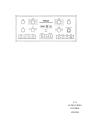
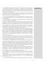
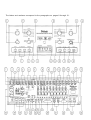
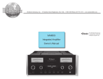
C39
AUDIO/VIDEO
CONTROL
CENTER
C39
AUDIO/VIDEO
CONTROL
CENTER
1.
2.
3.
4.
IMPORTANT
SAFETY
INSTRUCTIONS
THESE
INSTRUCTIONS
ARE TO PROTECT
YOU AND THE
MclNTOSH
INSTRUMENT.
BE SURE TO
FAMILIARIZE
YOURSELF
WITH THEM
Read all instructions - Read the safety and operating instructions before operating the instrument.
Retain Instructions - Retain the safety and operating instructions for future reference.
Heed warnings - Adhere to warnings and operating instructions.
Follow Instructions - Follow all operating and use instructions.
W A R N I N G : TO R E D U C E RISK O F FIRE OR ELECTRICAL S H O C K , D O NOT EXPOSE T H I S INS T R U M E N T TO RAIN OR MOISTURE.
5. Power Sources - Connect the power supply only to the type described in the operating instructions
or as marked on the unit.
6. Power-Cord Protection - Route power-supply cords so that they are not likely to be walked on or
pinched by items placed upon or against them, paying particular attention to cords at plugs,
convenience receptacles, and the point where they exit from the instrument.
7. Ventilation - Locate the instrument for proper ventilation. For example, the instrument should not
be placed on a bed, sofa, rug, or similar surface that may block ventilation openings; or, placed
in a built-in installation, such as a bookcase or cabinet, that may impede the flow of air through
the ventilation openings.
8. Heat - Locate the instrument away from heat sources such as radiators, heat registers, stoves, or
other appliance (including amplifiers) that produce heat.
9. Wall or Cabinet Mounting - Mount the instrument in a wall or cabinet only as described in the owner's
manual.
10. Water and Moisture - Do not use the instrument near water - for example, near a bathtub, washbowl,
kitchen sink, laundry tub, in a wet basement, or near a swimming pool, etc.
11. Cleaning - Clean the instrument by dusting with a dry cloth. Clean the panel with a cloth moistened
with a window cleaner.
12. Object and Liquid Entry - Do not permit objects to fall and liquids to spill into the instrument through
enclosure openings.
13. Nonuse Periods - Unplug the power cord from the AC power outlet when left unused for a long period
of time.
14. Damage Requiring Service - Service must be performed by qualified service personnel when:
A. The power supply cord or the plug has been damaged; or
B. Objects have fallen, or liquid has been spilled into the instrument; or
C. The instrument has been exposed to rain; or
D. The instrument does not appear to operate normally or exhibits a marked change in performance;
or
E. The instrument has been dropped, or the enclosure damaged.
15. Servicing - Do not attempt to service beyond that described in the operating instructions. All other
service should be referred to qualified service personnel.
16. Grounding or Polarization - Do not defeat the inherent design features of the polarized plug. Nonpolarized line cord adaptors will defeat the safety provided by the polarized AC plug.
17. CAUTION: TO PREVENT ELECTRICAL SHOCK DO NOT USE THIS (POLARIZED) PLUG
WITH AN EXTENSION CORD, RECEPTACLE OR OTHER OUTLET UNLESS THE BLADES CAN
BE FULLY INSERTED TO PREVENT BLADE EXPOSURE.
ATTENTION:
POUR PREVENIR LES CHOCS ELECTRIQUES PAS UTILISER CETTE
FICHE POLARISEE AVEC UN PROLONGATEUR, UNE PRISE DE COURANT OU UNE AUTRE
SORTIE DE COURANT, SAUF SI LES LAMES PEUVENT ETRE INSEREES A FOND SANS EN
LAISSER AUCUNE PARTIE A DECOUVERT.
The lightning flash with arrowhead, within an equilateral triangle, is intended to alert the
user to the presence of uninsulated "dangerous voltage" within the product's enclosure
that may be of sufficient magnitude to constitute a risk of electric shock to persons.
CAUTION: TO PREVENT THE RISK OF ELECTRIC SHOCK, DO NOT
REMOVE COVER (OR BACK). NO USER-SERVICEABLE PARTS INSIDE.
REFER SERVICING TO QUALIFIED PERSONNEL.
The exclamation point within an equilateral triangle is intended to alert the user to the
presence of important operating and maintenance (servicing) instructions in the literature
accompanying the appliance.
Copyright 1993 © by
Mcintosh Laboratory Inc.
WARNING: THIS UNIT IS CAPABLE OF PRODUCING HIGH SOUND
PRESSURE LEVELS. CONTINUED EXPOSURE TO HIGH SOUND
PRESSURE LEVELS CAN CAUSE PERMANENT HEARING IMPAIRMENT
OR LOSS. USER CAUTION IS ADVISED AND EAR PROTECTION IS
RECOMMENDED WHEN PLAYING AT HIGH VOLUMES.
2
Your decision to own this piece of Mcintosh Stereo Equipment ranks you at the very top
among discriminating music listeners. You now have "The Best". The Mcintosh dedication
to "Quality", is assurance that you will receive thousands of hours of musical enjoyment from
THANK
YOU
this unit.
Please take a short time to read the information in this manual. We want you to be as familiar
as possible with all the features and functions of your new piece of Mcintosh. This will ensure that you receive all the performance benefits this instrument can offer you, and that
it will become a highly valued part of your home music system.
The serial number, purchase date, and Mcintosh Laboratory Service Contract number are
important to you for possible insurance claim or future service. Record this information here.
Serial Number
Purchase Date
Service Contract Number
Upon application, Mcintosh Laboratory provides a Service Contract to the original purchaser.
Your Mcintosh Authorized Service Agency can expedite repairs when you provide them with
the Service Contract.
SERVICE CONTRACT
INTRODUCTION
HOW TO INSTALL THE C39
4
5, 6
6
HOME THEATER AUDIO CHANNEL CONFIGURATION WITH
DOLBY PRO LOGIC TM AND HOME THX® AUDIO
FRONT PANEL CONTROLS, SWITCHES AND PUSHBUTTONS
C39 HAND HELD REMOTE CONTROLLER
THE REAR PANEL AND HOW TO MAKE CONNECTIONS
HOW TO SET UP YOUR MclNTOSH HOME THEATER
7
8, 9, 10, 11, 12, 13
13, 14, 15
15, 16, 17, 18, 19, 20, 21
21, 22
HOME THEATER LAYOUT
23
HOME THEATER HOOKUP
24
MclNTOSH HOME THEATER SURROUND SOUND
VOLUME LEVEL CALIBRATION
SPECIFICATIONS
25, 26, 27, 28
29, 30
CUSTOM INSTALLATION DRAWING
31
FOLD-OUT DRAWINGS OF FRONT AND BACK PANELS OF C39
32
3
TABLE OF
CONTENTS
TAKE ADVANTAGE OF 3 YEARS OF CONTRACT SERVICE. . .
FILL IN THE APPLICATION NOW.
Your C39 Audio/Video Control Center will give you many years of satisfactory performance.
If you have any questions, please contact,
Mcintosh Laboratory Inc.
2 Chambers Street
Binghamton, New York 13903-2699
Phone: 607-723-3512
An application for A THREE YEAR SERVICE CONTRACT is included with this manual.
MclNTOSH
THREE YEAR
SERVICE
CONTRACT
The terms of the contract are:
1. If the instrument covered by this contract becomes defective, Mcintosh will provide all parts,
materials, and labor needed to return the measured performance of the instrument to the
original performance limits free of any charge. The service contract does not cover any
shipping costs to and from the authorized service agency or the factory.
2. Any Mcintosh authorized service agency will repair all Mcintosh instruments at normal
service rates. To receive the free service under the terms of the service contract, the service contract certificate must accompany the instrument when taken to the service agency.
3. Always have service done by a Mcintosh authorized service agency. If the instrument is
modified or damaged as a result of unauthorized repair the service contract will be cancelled. Damage by improper use or mishandling is not covered by the service contract.
4. The service contract is issued to you as the original purchaser. To protect you from
misrepresentation this contract cannot be transferred to a second owner.
5. Units in operation outside the United States and Canada are not covered by the Mcintosh
Factory Service Contract, irrespective of the place of purchase. Nor are units acquired
outside the USA and Canada, the purchasers of which should consult with their dealer
to ascertain what, if any, service contract or warranty may be available locally.
4
Mcintosh Laboratory has earned a world wide reputation for the technical superiority of
its contributions to high quality sound reproduction. The advanced level of Mcintosh product
innovations has integrity proven by time. The legendary reliability of Mcintosh products is a
matter of record since 1949. The "Classic Mcintosh" design is acknowledged as the most
outstanding in the audio industry.
Mcintosh products are designed to be maximum "User Friendly". Anyone can enjoy using
them. Ease of maintenance is another Mcintosh design philosophy that contributes to the
long useful operating life of all Mcintosh products.
The C39, Audio/Video Control Center is a full featured remote control center for a complete Mcintosh Home Theater System. It provides six audio channels with the added features
of video switching.
The C39 includes all the required Dolby Pro Logic™ decoding circuits to reproduce Dolby
Surround™ encoded movie soundtracks.
You also can enjoy the enhanced movie sound track reproduction possible from Home
THX® Audio processing circuits by having your Mcintosh dealer install the optional Mcintosh
THX-M Module in your C39. The Home THX©; Audio System is a licensing program of Lucasfilm
Ltd., which defines new technologies and quality standards for accuracy in home theaters.
The C39 includes a built-in noise generator and the controls necessary for accurate volume
level calibration of all six channels when setting up a home theater.
The C39 has the added feature of the Mcintosh designed " H A L L " signal processing circuits. The "HALL" feature allows you to enhance the realism of two channel program sources
such as a compact disc. The Left and Right signals are reproduced through the Left and Right
Front loudspeakers. The same signals are combined and fed to the center channel loudspeaker
as mono center fill. The combined left and right are also fed to a digital processor with variable
time delay for the surround loudspeakers. If a subwoofer is used in the system, it will also
operate in the " H A L L " mode.
The C39 includes a 25 pin connector on the rear panel to accommodate a single subminiature " D " computer type cable which fits a similar connector on a Mcintosh MC7106
six channel power amplifier. This cable carries all six audio signals and AC power control
to the MC7106 for a complete Mcintosh Home Theater System.
The C39 has built-in capability for remotely controlling two separate listening areas. The
LISTEN signals are defined as Area "A" which is usually the main area where all the equipment is located. The RECORD signals are available at a pair of outputs marked " B " , and can
be used for a remote area with its own dedicated power amplifier and pair of speakers. The
desired program can be selected in Area " B " with the HR39 Hand Held Remote Controller
transmitting to a wall mounted IR sensor, or from a WK-1 keypad.
Data ports are provided for twelve audio and video remote controlled accessories. This
feature allows you to control a compatible unit by transmitting with its hand held remote controller directly to a C39 sensor. Another data port connects to the optional Mcintosh HC-1
Home Controller to allow control of accessories or appliances.
The optional Model RCT-1, Remote Control Translator is also available to interconnect with
the C39. The RCT-1 is a learning device which will allow the C39 to remotely control other
brands of products.
The convenience of C39 remote control operation is enhanced by its capability to directly
interface with the Mcintosh CR10 Remote Control System. The CR10 can add an additional
four remote areas of control.
The C39 includes twelve pairs of high level audio inputs. Seven inputs are for all the tradi-
5
INTRODUCTION
INTRODUCTION
tional audio program sources. A pair of low level inputs is included for a moving magnet phono
cartridge. Six of the audio inputs are for the audio portion of an audio/video signal. Six matching standard and S Video inputs are also included. The C39 will simultaneously switch the
six video and corresponding audio signals.
The C39 uses digital Logic integrated circuits to drive Electromagnetic Switches for all input, output and operating functions. This is the most reliable and distortion free switching
available.
Separate Record and Listen circuits allow recording from one source while listening to
another with audio or audio/video signals. A continuously variable Active Loudness control
allows loudness compensation to be selected for any setting of the volume control. The
Loudness control circuit elements are removed from the circuit path when the control is in
the flat or fully counterclockwise position.
Bass and Treble tone controls provide 12dB of boost or cut. At the center "Flat Response"
or detent position of the tone controls, all tone control circuit elements are removed from the
signal path. Other features include a precision digital driven six channel volume control, front
panel digital volume level indicator and Balanced outputs for the Left and Right output signals.
Front panel Camcorder inputs and a headphone output are also provided. These connections are hidden behind a motor driven door which is opened and closed by a convenient
front panel Access pushbutton. The Mcintosh C39 "Classic Mcintosh" all glass front panel
has all control, switch and pushbutton nomenclature illuminated.
The Mcintosh Home THX Audio licensed C39 Audio/Video Control Center, MC7106 six channel power amplifier and a set of Mcintosh HT Series Home Theater loudspeakers will make
a perfect "Mcintosh Quality" Home Theater system. Your Mcintosh dealer can assist you
in setting up all the various components of your Mcintosh Home Theater to ensure you will
receive the best possible performance.
DOLBY SURROUND, PRO LOGIC and the Double-D Symbol are trademarks of Dolby Licensing Laboratory.
Home THX®Audio is a registered trademark of Lucasfilm Ltd.
The C39 can be placed upright on a table or shelf, standing on its own plastic feet. It can
HOW TO
INSTALL
THE C39
also be installed in an optional Mcintosh L74 equipment cabinet. Follow the mounting instructions enclosed with the L74 cabinet.
The C39 can be custom installed in a piece of furniture or cabinet of your choice. The
required panel cutout and unit dimensions are shown on Page 31 of this manual.
Always provide adequate ventilation for your C39, even though it develops very little heat.
Cool operation insures the longest possible operating life for any electronic instrument. Do
not install your C39 directly above a heat generating component such as a high powered
amplifier. In a system stack, the power amplifier should always be at the top. If all the components are installed in a single cabinet, a quiet running ventilation fan can be a definite asset
in maintaining all the system components at their coolest possible operating temperatures.
A custom cabinet installation should provide the following recommended minimum spacing dimensions for cool operation. Allow at least 1 1/2 inches (3.8cm) above the unit so airflow
is not obstructed. Allow 17 1/2 inches (44.5cm) depth behind the mounting panel, which includes clearance for connectors. Allow 1-1/8 inches (2.9cm) in front of the mounting panel
for knob clearance.
6
All movies produced by major film companies have Dolby Stereo soundtracks.
When they
reach you via home video sources, the Dolby Surround encoding remains intact. Dolby Pro
Logic relies on the same decoding technology as the professional cinema processors to
decode the movie sound tracks that are found on video. The decoding process results in four
separate sound tracks which are Left Front, Center, Right Front, and Surround. The Dolby
Pro Logic decoded surround signals are monaural, but are reproduced by a non-directional
loudspeaker on each side of the listening area to help diffuse the sound. The Dolby Surround
concept is the heart of the Home Theater audio and video experience.
Dolby Surround encoding is also used for MTS and satellite broadcasts as well as other
audio-only program sources such as compact discs. Use the C39 CINEMA 1 mode with its
Dolby Pro Logic processing to enjoy listening to these other program sources.
Home THX Audio circuits further process all the Dolby Pro Logic decoded signals including
the generation of separate spatially expanded left and right surround signals. Home THX Audio
also specifies that a subwoofer be used. A Home THX Audio system therefore requires six
discrete
audio
channels
and six
corresponding
loudspeakers.
The C39 provides six audio channels to take full advantage of the exciting sound reproduction capabilities of a Dolby Surround encoded movie sound track.
When the Mcintosh THX-M
module is installed in the C39 the audio enhancements possible by Home THX Audio signal
processing also will be available.
Descriptions of the functions of each channel of a Dolby Surround soundtrack as decoded
by Dolby Pro Logic and the addition of Home THX Audio processing will assist you in better
understanding the use of the various controls, switches and operating procedures of your C39.
DOLBY SURROUND LEFT FRONT and RIGHT FRONT
These two channels are stereo channels in the traditional sense. The left and right signals
provide ambience, depth and spaciousness for reproduction of music and sound from a Dolby
Pro Logic decoded movie soundtrack. The front channels also reproduce similar information
from a two channel stereo source such as a compact disc or audio tape.
DOLBY SURROUND CENTER FRONT
Dolby Surround movie soundtracks are encoded with a Center channel, which also includes
dialog information, to increase the realism of the home theater experience. The Dolby Pro
Logic decoded Center channel is reproduced through a loudspeaker placed in the front center
location, either above or below the viewing screen. A Center loudspeaker provides greater
intelligibility and localization of a movie dialog regardless of the seating position.
DOLBY SURROUND LEFT and RIGHT SURROUND
Dolby Surround soundtracks are encoded with a specially processed surround sound signal.
When decoded by Dolby Pro Logic processing circuits, the surround sounds can include all
types of acoustical information and sound effects that enhance your listening enjoyment. The
Dolby Pro Logic decoded surround sound channel is monaural, however, it is reproduced
through two separate loudspeakers placed on the left and right walls of the listening area.
The surround loudspeakers should radiate sound in a nondirectional manner, allowing the
listeners to hear only a diffused sound. Properly installed surround loudspeakers will provide
ambience, and should not distract from the direct sound reproduced by the front loudspeakers.
H O M E THX AUDIO SURROUND CHANNELS
Home THX circuits add additional processing to all the original Dolby Pro Logic decoded
signals. The monaural surround signal is further processed into two separate spatially expanded left and right surround signals.
7
HOME THEATER
AUDIO CHANNEL
CONFIGURATION
WITH DOLBY
PRO LOGIC™
AND HOME
THX AUDIO
HOME THEATER
AUDIO CHANNEL
CONFIGURATION
WITH DOLBY
PRO LOGIC™
AND HOME
THX AUDIO
There are specific Home THX Audio requirements for surround sound level calibration. This
information is included in the manual section "MclNTOSH HOME THEATER SURROUND
SOUND VOLUME LEVEL CALIBRATION".
SUBWOOFER
Home THX Audio specifications require a subwoofer to be used in a home theater system.
A subwoofer loudspeaker is designed to reproduce only the lowest audio frequencies, which
are essentially non-directional. The C39 meets this requirement by combining the Left, Right
and Center channel signals and feeding them through a filter that allows only the bass frequencies of 80Hz and lower to be fed to the subwoofer outputs. The non-directional sound
characteristics of a subwoofer allow it to be placed in a wide range of room locations.
A well designed subwoofer will reproduce the low frequency music and sound effects present in today's action movie sound tracks with dramatic impact. Using a discretely placed
subwoofer also allows the optional use of somewhat smaller and less obtrusive front
loudspeakers.
Detailed information on Home Theater loudspeaker setup is covered in the manual enclosed with your Mcintosh HT Series Home Theater loudspeakers.
FRONT PANEL
CONTROLS,
SWITCHES
AND
PUSHBUTTONS
The C39 can be remotely controlled. Most of the operating functions performed at the front
panel, also can be done by the C39 Hand Held Remote Controller. The following information
refers only to the front panel. Another section of this manual explains the operation of the
C39 Hand Held Remote Controller.
The back cover of this manual folds out to show drawings of the front and rear panels of
the C39. This will assist you in identifying and locating the front panel controls, switches,
pushbuttons and the rear panel connectors and switches. The letters and numbers on the
drawings refer to the information that follows.
A. BASS and TREBLE
Provides 12dB boost and cut, with neutral flat response at the center detent position. The
Bass and Treble controls affect the LEFT and RIGHT Balanced Outputs, the LEFT FRONT,
CENTER, RIGHT FRONT and SUBWOOFer Unbalanced Outputs. These are all Area "A" Outputs. The corresponding channels of the 6 CHANNEL OUTPUT connector are also affected.
The VCR1, VCR2, TAPE 1, TAPE 2 and Area " B " Outputs are not affected by the Bass and
Treble controls.
B. RECORD
Selects any of the 12 audio input program signals that will feed the TAPE 1, TAPE 2, VCR
1, VCR 2 and Area "B " Audio Outputs.
Area "B" must first be turned ON in Area "B", by a keypad or remote controller
transmitting to an Area "B" sensor, before the Area "B" outputs will operate.
The audio signals for SATellite, TV, Laser Video, VCR1, VCR2 and V-AUX will have their corresponding video signals switched simultaneously. The selected video RECORD signals will
appear at the MONitor B, VCR1 and VCR2 VIDEO Outputs. This allows the selected program
signals to be fed to an external TV monitor, as well as to one or two VCR units for recording
purposes.
8
All audio or video tape recording must be setup manually in Area "A". Prior to a
recording session, always press the REC (Record) LOCK pushbutton to disable all
remote sensors or keypads
to avoid accidental recording disruption.
C. MODE (Selects the operating configuration)
MONO: All left and right channel signals are combined for Mono operation and fed to the
LEFT FRONT, RIGHT FRONT, Balanced, Unbalanced and the corresponding 6 CHANNEL connector outputs. The combined Mono signals of 80Hz and lower are also fed to the SUBWOOFER Output.
The Unbalanced CENTER Output can be activated in MONO by setting the rear panel
CENTER FILL Switch (25), to the ON position. This allows a Center channel loudspeaker to
be used during MONO operation.
STEREO: Left channel signals are fed to the LEFT FRONT Unbalanced and the LEFT Balanced Outputs. Right channel signals are fed to the RIGHT FRONT Unbalanced and the RIGHT
Balanced Outputs. The Left and Right signals at 80Hz and lower are combined and fed to
the SUBWOOFer Output.
The Unbalanced CENTER Output, which contains the combined left and right channel
signals can be activated by setting the rear panel CENTER FILL Switch (25), to the ON position. This allows a Center channel loudspeaker to be used during STEREO operation.
HALL: ENHANCES TWO CHANNEL AUDIO SIGNALS. Left channel signals are fed to the
LEFT FRONT Unbalanced and LEFT Balanced Outputs. Right channel signals are fed to the
RIGHT FRONT Unbalanced and RIGHT Balanced Outputs. The Left and Right signals of 80Hz
and lower are combined and fed to the SUBWOOFer Output. The combined Left and Right
audio signals are also fed to a Digital Processor, time delayed, and then fed to the LEFT SURround and RIGHT SURround Outputs. The time delay can be adjusted by the front panel DELAY
(ms) Switch.
The Unbalanced CENTER Output can be activated in HALL mode by setting the rear panel
CENTER FILL Switch (25), to the ON position. This allows a Center channel loudspeaker to
be used in the HALL operating mode.
CINEMA 1, TO REPRODUCE DOLBY SURROUND, PRO LOGIC DECODED MOVIE
SOUNDTRACKS:
Audio signals from a Dolby Surround encoded movie soundtrack are fed to the C39 Dolby
Pro Logic processing and decoding circuits which produce the following outputs.
Left audio signals are fed to the LEFT FRONT Unbalanced and LEFT Balanced Outputs.
Right audio signals are fed to the RIGHT FRONT Unbalanced and RIGHT Balanced Outputs.
The Dolby Pro Logic processing circuits also decode the center channel signals which include dialog, and feed them to the Unbalanced CENTER Output. The Dolby Pro Logic processed monaural surround sound signals are fed to the LEFT Surround and RIGHT Surround
outputs.
The Left, Right and Center signals of 80Hz and lower are combined by the C39 and fed
to the SUBWOOFer Output.
The Dolby Pro Logic Indicator on the C39 front panel lights when the MODE Switch is in
CINEMA 1 position.
Dolby Surround
encoding
is also used for MTS and satellite broadcasts as well as
other audio-only program sources such as compact discs. Use the C39 CINEMA 1 mode
with its Dolby Pro Logic processing to enjoy listening to these other program sources.
9
FRONT PANEL
CONTROLS
SWITCHES
AND
PUSHBUTTONS
FRONT PANEL
CONTROLS,
SWITCHES
AND
PUSHBUTTONS
CINEMA 2, H O M E THX AUDIO: TO REPRODUCE DOLBY SURROUND, PRO LOGIC
DECODED MOVIE SOUNDTRACKS WITH H O M E THX AUDIO ENHANCEMENT.
The CINEMA 2 or Home THX Audio mode of operation is possible only when the
optional Mcintosh
THX-M Module has been installed in the C39.
The four Dolby Pro Logic processed output signals are fed to the Home THX Audio circuits
in the THX-M module for further processing and enhancement which produce the following
six outputs.
Left audio input signals are fed to the LEFT FRONT Unbalanced and LEFT Balanced Outputs. Right audio signals are fed to the RIGHT FRONT Unbalanced and RIGHT Balanced Outputs. The processing circuits also feed center channel signals which include dialog, to the
Unbalanced CENTER Output. The Dolby Pro Logic decoded monaural surround signals are
then further processed into separate spatially expanded left and right surround signals, which
are fed to the LEFT Surround and RIGHT Surround Unbalanced outputs.
The Left Front, Center and Right Front signals of 80Hz and lower are also combined by
the C39 and fed to the SUBWOOFer Output.
With the Mcintosh THX-M Module installed in the C39, the front panel Home THX Audio
Indicator lights when the MODE Switch is in CINEMA 2 position. The Dolby Pro Logic front
panel indicator stays lit in both CINEMA 1 and CINEMA 2 mode.
All signals fed to the six unbalanced outputs also are fed to corresponding pins
on the rear panel 6 CHANNEL
OUTPUT connector.
D. DISPLAY WINDOW
1. The Dolby Pro Logic™ indicator lights when the C39 is switched to CINEMA 1 or
CINEMA 2 Mode.
2. The Home THX Audio indicator lights when the C39 is in CINEMA 2 Mode, and the
optional THX-M Module is installed.
The optional Mcintosh THX-M Module must be installed in the C39 for the Home
THX Audio indicator to light.
3. The % (Percentage), VOLUME indicator always lights when the C39 is turned on and
operating. The selected volume is indicated as a percentage of maximum, with numbers
reading from 0 to 99. The indicator also shows the amount of volume level trim that is used
for each channel during the surround level calibration procedure.
E. LISTEN
Selects any of the 12 audio input program signals that will feed the six Unbalanced outputs, the two Balanced outputs and the SIX CHANNEL OUTPUT connector. These are Area
"A" signals. The audio signals for Satellite, TV, Laser Video, VCR1, VCR2 and V-AUX will have
their corresponding Video signals switched simultaneously. The selected LISTEN video signals
will appear at the MON A Video Outputs. You can select either audio only programs for listening, or audio/video programs for listening and viewing.
The VCR1, VCR2, TAPE 1 and TAPE 2 and Area " B " outputs are not affected by the LISTEN
switch.
F. VOLUME
Adjusts the volume level of all six Unbalanced outputs, the two Balanced outputs and the
6 CHANNEL OUTPUT Connector. These are Area "A" outputs.
10
The VCR1, VCR2, TAPE 1, TAPE 2 and Area " B " Outputs are not affected by the front panel
VOLUME Control.
G. LOUDNESS and BALANCE (Concentric Controls)
BALANCE control, (large outer knob): Adjusts the volume of the Left and Right channels
relative to each other. The BALANCE control affects only the LEFT FRONT, RIGHT FRONT
Unbalanced, LEFT and RIGHT Balanced, Area "A" Outputs and the six channel connector.
The BALANCE Control is effective in all five modes of operation.
L, (Left): Turn the control to the left to accent the left channels by reducing the volume
of the right channels.
R, (Right): Turn the control to the right to accent the right channels by reducing the volume
of the left channels.
The VCR1, VCR2, TAPE 1, TAPE 2 and Area " B " Outputs are not affected by the BALANCE
Control.
LOUDNESS control, (small inner knob): Provides frequency response contoured to compensate for the behavior of the human ear at softer listening levels. At the fully
counterclockwise detent position, the frequency response is perfectly flat and the loudness
circuit components are removed from the signal path. Turn the control clockwise to modify
the frequency response in the correct proportion required for softer listening levels. The compensated frequency response is not affected by changes in the volume control settings. First
adjust the VOLUME Control for the desired listening level, then adjust the LOUDNESS Control to the setting you personally prefer.
The LOUDNESS Control affects the LEFT FRONT, CENTER, RIGHT FRONT, SUBWOOFer
Unbalanced, LEFT and RIGHT Balanced outputs and the corresponding outputs on the 6
CHANNEL Connector. These are Area "A" Outputs. The LOUDNESS Control is effective in
all five modes of operation.
The VCR1, VCR2, TAPE 1, TAPE 2 and Area " B " Outputs are not affected by the LOUDNESS
Control.
NOTE: The flat frequency response setting of the LOUDNESS Control is at the FULLY
COUNTER CLOCKWISE position, not at the center or 12 o'clock position where the
BALANCE Control is
neutral.
H. SYS CAL, SYStem CALibrate, (SUR CAL)
Allows the volume level of all six channels to be accurately set using the built-in C39 noise
generator. Calibration includes individual channel volume level adjustment or trimming which
may be required due to room geometry or differences in amplifiers or speakers. The calibration can be done by cycling through the six channels automatically or manually, depending
on the setting of the C39 rear panel SURROUND CALIBRATE switch. The chosen level calibration settings are then retained in the Control Center memory.
Surround sound calibration is possible in the HALL, CINEMA 1 and CINEMA 2 Modes.
Normal listening levels and surround calibration volume levels can be set as you desire
for HALL or CINEMA 1 Modes. For CINEMA 2 or Home THX® Audio Mode, the requirements
are
more
specific.
THEATER SURROOUND SOUND
cedures for both CINEMA
Refer
to
the
VOLUME LEVEL
manual
section
"MclNTOSH
HOME
CALIBRATION" for calibration pro-
1 and CINEMA 2.
An LED lights above the SYS CAL, (SUR CAL), pushbutton during calibration operation.
11
FRONT PANEL
CONTROLS,
SWITCHES
AND
PUSHBUTTONS
FRONT PANEL
CONTROLS,
SWITCHES
AND
PUSHBUTTONS
I. SURR LEVEL, SURRound LEVEL, (SUR CAL), UP ( ) or DOWN ( )
UP ( ) and DOWN ( ) pushbuttons adjust the volume level match of all six channels as
described in the manual section "MclNTOSH HOME THEATER SURROUND SOUND VOLUME
LEVEL CALIBRATION".
J. SURR PROC (SURRound PROCessor)
Press the SURR PROC pushbutton if you wish to remove all signal processing functions
in HALL, CINEMA 1 or CINEMA 2 modes, and return to normal STEREO mode. Press again
to restore signal processing.
An LED above the SURR PROC pushbutton turns on to indicate when signal processing
is active.
K. SENSOR
The Infrared sensor that accepts control signals from the C39 Hand Held Remote Controller.
L. CAMCORDER (S VIDEO, L and R AUDIO, Behind Door)
A Camcorder with audio and either S or standard video outputs can be connected to the
C39 on the front panel for convenient audio/video playback. To access the Camcorder connections, press the ACCESS pushbutton to open the motor driven door. When the door opens,
the rear panel V-AUX VIDEO inputs are automatically switched to the front panel Camcorder
inputs. The rear panel V-AUX AUDIO inputs are automatically switched to the front panel Audio
jacks when audio cables are inserted into the Camcorder jacks. Press ACCESS again to close
the door.
M. PHONES (Behind Door)
Plug in a pair of low impedance dynamic headphones to this jack for two channel stereo
headphone listening. The headphone outputs are configured so you always hear the full two
channel stereo information which maintains the phantom center channel, even when the surround sound signals are feeding the six loudspeakers in CINEMA 1 or CINEMA 2 modes. Access the PHONES jack by pressing the ACCESS pushbutton to open the motor driven door.
N. DELAY
This switch allows you to change the time delay of the signals in the surround sound channels. The numbers indicate the time delay in milliseconds when the C39 is in CINEMA 1 (Dolby
Pro Logic), or CINEMA 2 (Home THX Audio) operating modes. The HALL mode of operation
has slightly longer delay times. Refer to the chart below for the exact delay times for each mode.
The CENTER, 20ms position, is the recommended initial setting for all operating modes using surround sound.
The longer delay times simulate the listening effect of a larger listening room or hall. The
shorter delay times simulate a smaller or more intimate listening area. You may wish to experiment with different delay settings based on your personal preferences.
CINEMA 1 and CINEMA 2 MODE DELAY TIMES
The delay times for each switch setting indicated on the front panel are rounded to 1ms.
FRONT PANEL INDICATION
12
ACTUAL TIME DELAY IN MILLISECONDS
12
12.2ms
16
16.4ms
20 (Recommended Setting)
20.5ms
24
24.6ms
28
28.7ms
HALL MODE DELAY TIMES
In the HALL operating mode, the time delays are slightly longer than the panel indications.
Set the delay according to your personal preference. The shorter delay times simulate a smaller
room, while the longer delays simulate a large room or concert hall.
FRONT PANEL INDICATION
ACTUAL TIME DELAY IN MILLISECONDS
12
FRONT PANEL
CONTROLS,
SWITCHES
AND
PUSHBUTTONS
16.4ms
16
32.8ms
20 (Recommended Setting)
49.2ms
24
65.1ms
28
81.9ms
O. ACCESS
Press the ACCESS pushbutton to open the motor driven door over the Camcorder and Headphone connectors. As soon as the door opens, the rear panel V-AUX VIDEO inputs are switched
to the front panel Camcorder Video inputs. The V-AUX AUDIO inputs are automatically switched
to the front panel Audio inputs when audio cables are inserted into the Camcorder jacks.
Press ACCESS again or turn the front panel VOLUME control to close the door.
P. REC LOCK (RECord LOCK)
Press this pushbutton to disable any remote AREA " B " sensors or keypads. This avoids
the possibility of someone accidentally sending a control signal from AREA " B " that would
disrupt a recording process set up in Area "A". A red LED above the REC LOCK pushbutton
lights to indicate AREA " B " and its sensors are turned off.
Q. MUTE
Press MUTE to silence all six audio output channels in Area "A". A Red LED above the
MUTE pushbutton will blink on and off to indicate that the signals are muted. Press MUTE
again or turn the front panel VOLUME control to restore normal audio operation. The front
panel MUTE does not affect the TAPE or Area " B " Outputs.
Mute Area " B " by using the hand held remote controller transmitting to a wall sensor or
a keypad in Area " B " . A red LED will blink on and off in either the wall sensor or a keypad
in Area " B " to indicate the area is muted.
R. POWER
Press POWER to turn on the C39 system. The front panel will illuminate and show the program signals and operating modes selected in Area "A". Only the Area A outputs and Area
"A" power amplifier will turn on. The Area "A" power amplifier AC power cord must be connected to, or controlled by, the C39 rear panel Area "A" AC outlet.
Area " B " Outputs and the dedicated Area " B " power amplifier can be turned on
only in Area " B " by a keypad or remote controller transmitting to an Area " B " sensor.
The Area " B " power amplifier AC power cord must be connected to, or controlled by, the
C39 rear panel Area " B " AC outlet.
The descriptions and functions of the C39 Remote Controller pushbuttons refer to the
numbers on the drawing.
1. Select any of the 12 Audio and Audio/Video LISTEN program signals in Area "A". Select
any of the same 12 Audio and Audio/Video program signals in Area " B " . The selected Area
" B " signals are also the RECORD program signals.
13
C39
HAND HELD
REMOTE
CONTROLLER
C39
HAND HELD
REMOTE
CONTROLLER
2. Select Tuner station presets or relay
operation on the HC-1 Home Controller. First
press the HOME pushbutton (4) and then the
desired pushbuttons 0 through 9 (2) within
five seconds to activate the relays on the
HC-1.
The number pushbuttons also function
with the RCT-1 Remote Control Translator,
when it is programmed to allow the C39 to
remotely control other brand products.
3. Select CD Player, CD Changer or tape
recorder functions.
Using a Mcintosh a SINGLE DISC CD
PLAYER, STOP, BACK TRACK (
TRACK (
), NEXT
) and PLAY functions can be
performed.
Using a Mcintosh CD CHANGER, STOP,
BACK TRACK (
), NEXT TRACK (
)
and PLAY functions can be performed while
a disc is playing.
When the CD changer is in the STOP position, BACK TRACK (
DISC and NEXT TRACK (
) selects the SINGLE
) selects which of the other six discs you wish to play. After
pressing STOP, the first time you press NEXT (
), disc number 1 is selected. Press again
as desired to select discs 2 through 6.
FOR EXAMPLE: To select disc number 6 from the single disc play mode, press STOP and
then NEXT (
) six times. To select disc number 2, press STOP and then press NEXT (
twice. To select the disc in the SINGLE disc slot, press STOP and then press BACK (
)
) once.
4. Press HOME to operate the HC-1 Home Controller functions. Within five seconds press
a pushbutton number from 0 to 9 to control the desired relays on the HC-1,
5. Press SYS OFF to turn the entire C39 system off from either Area "A" or Area " B " after
the SYS OFF is activated.
6. Press POWER to turn on the main system in Area "A". Press in Area " B " to turn on just
Area " B " Outputs and power amplifier. Each time Area " B " is turned on, the TUNER input
is automatically selected at a volume level 50dB below maximum. The Area "A" power amplifier
and dedicated Area " B " power amplifier AC power cords must be connected to or controlled
by their respective C39 rear panel Area "A" and Area " B " AC outlets.
7. Select Tuner functions of AM, FM or SEEK. When an RCT-1 Translator is being used to
control a TV set, the SEEK UP or DOWN pushbuttons can be used to change TV channels.
8. First press TUNER and then press REVIEW to start the automatic audition of each of the
preset stations stored in tuner memory of a compatible Mcintosh tuner. Press REVIEW again
to stop on the desired preset. Cancel the REVIEW process by pressing REVIEW a second
time, or pressing any other Tuner function pushbutton.
9. E (ENTER or EXTRA) is used for controlling functions of an accessory component when
an RCT-1 Remote Control Translator is being used.
14
10. Press MUTE to mute the audio signals separately in either Area "A" or " B " . Area "A"
muting is in dicated by a Red LED above the MUTE pushbutton that blinks on and off. To
unmute Area "A", press MUTE a second time, press an UP ( ) or DOWN ( ) VOLUME pushbutton or turn the front panel VOLUME control.
11. SP (Surround Processor pushbutton switches Area "A" surround signal processing func-
C39
HAND HELD
REMOTE
CONTROLLER
tions IN or OUT, in HALL, CINEMA 1 or CINEMA 2 modes. When signal processing is switched OUT, the C39 is in normal STEREO operating mode.
An LED above the front panel SURR PROC pushbutton turns on to indicate signal processing is active.
12. Press either the UP ( ) or DOWN ( ) SURROUND push button to calibrate individual channel level balance during surround sound calibration procedure on all six channels. You can
also raise or lower the surround sound levels during normal operation with these pushbuttons.
13. Press UP VOLUME ( ) to raise the listening volume and DOWN VOLUME ( ) to lower
the listening volume. All six channels are affected.
The VCR1, VCR2, TAPE1, and TAPE2 Outputs are not affected by the remote volume
pushbuttons.
14. Press ACC (ACCessory) OFF or ACC ON to control the AC Power of an accessory component that is being used in combination with an RCT-1 Remote Control Translator.
HOW TO INSTALL BATTERIES IN THE C39 HAND HELD REMOTE CONTROLLER
Slide open the battery compartment. Insert two type AA batteries into the compartment,
making sure to observe the battery polarities indicated in the battery compartment.
When the batteries are nearing exhaustion, the effective range of the remote controller
decreases, and MAY even fail to operate. In this case, replace both batteries with fresh ones.
NOTE:
1. Do not mix old and new batteries. Use ONLY batteries that are new.
2. Make sure both batteries are of the same type and identical.
3. To prevent damage caused by possible battery leakage, remove the batteries from the
remote controller if it is not going to be used for an extended period of time.
4. Never dismantle batteries or dispose of them in a fire, as they may explode. Dispose of
old batteries in an approved method for proper safety.
Use
high
quality cables
used
with your C39
from
your
Mcintosh
Control
to
interconnect
Center.
Audio/Video
This
Home
the
audio and
will ensure
Theater and
video
the
accessory equipment
best possible performance
Stereo
system.
Your
Mcintosh
dealer can advise you on the types and lengths of cables best suited for your particular
installation.
ALL SIGNALS FED TO THE SIX UNBALANCED OUTPUTS ALSO APPEAR AT THE C39
REAR PANEL 6 CHANNEL OUTPUT CONNECTOR AND ARE FED THROUGH A 25 CONDUCTOR SUBMINIATURE "D" MALE-TO-FEMALE COMPUTER
CHING
CONNECTOR
ON A
TYPE CABLE TO A MAT-
MCINTOSH MC7106 SIX CHANNEL
POWER AMPLIFIER.
15
THE
REAR PANEL
AND
HOW TO MAKE
CONNECTIONS
THE
REAR PANEL
AND
HOW TO MAKE
CONNECTIONS
THE CHANNEL ALLOCATION IS AS FOLLOWS:
CHANNEL 1
Center Front
CHANNEL 2
Left Surround
CHANNEL 3
Left Front
CHANNEL 4
Right Front
CHANNEL 5
Subwoofer
CHANNEL 6
Right Surround
1. SUR (SURround)
Connect a pair of cables from the SURround AUDIO OUTPUT jacks to the inputs of the
power amplifier channels which will feed left and right surround sound loudspeakers.
2. CENTER
Connect a cable from the CENTER AUDIO OUTPUT jack to the amplifier channel that will
feed a center front loudspeaker.
3. SUBWOOF (SUBWOOFer)
Connect a cable from the SUBWOOFer AUDIO OUTPUT jack to the amplifier channel
feeding a subwoofer loudspeaker. This output includes only audio frequencies of 80Hz and
lower.
4. FRONT
Connect a pair of cables from the FRONT AUDIO OUTPUT jacks to the left and right front
amplifiers. Use these outputs if you are operating the C39 as a conventional two channel
stereo control center.
The same signals that feed the FRONT AUDIO OUTPUT jacks also feed the BALANCED
OUTPUTS, (See No. 18.)
5. VCR1, VCR2
Connect cables from the C39, VCR1 and VCR2 AUDIO OUTPUT jacks to the high level
audio inputs of two VCR units. These connections allow you to record the audio portion of
ANY input selected by the RECORD switch.
6. TAPE 1, TAPE 2
Connect cables from the C39, VCR1 and VCR2 AUDIO OUTPUT jacks to the high level
inputs of two audio tape recorders. These connections allow you to record the audio portion
of ANY input selected by the RECORD switch.
7. RECORD PROCESSOR, FROM and TO
An external signal processor can be added to the C39 which will affect audio recording
signals only at the VCR1, VCR2, TAPE 1 and TAPE 2 audio outputs. The PROCESSOR FROM
jacks have built-in switching contacts that allow normal signals to pass through when no cables
are connected. When an external signal processor is properly connected, the program signals
will feed to the processor from the C39 PROCESSOR TO jacks, and return to the C39 at the
PROCESSOR FROM jacks.
Connect a pair of cables from the external processor Outputs to the C39 PROCESSOR
FROM jacks. Connect another pair of cables from the external processor Inputs to the C39
PROCESSOR TO jacks.
WHEN AN EXTERNAL SIGNAL
PROCESSOR JACKS,
16
PROCESSOR IS CONNECTED TO
THE C39 RECORD
THE PROCESSOR MUST BE TURNED ON AND OPERATING,
OR
IN BYPASS MODE, FOR THE PROGRAM SIGNALS TO BE FED TO THE VCR, TAPE OR
AREA
"B" AUDIO OUTPUTS.
8. VCR1, 2 and V-AUX (Auxiliary)
Connect cables from the Audio Outputs of VCR units or other similar Audio/Video accessories to these three AUDIO INPUTS.
9. LV (Laser Video)
Connect a pair of cables from a Laser Video Disc player Audio Outputs to the LV AUDIO
INPUTS.
10. TV
Connect a pair of cables from the Audio Outputs of a TV set, TV Monitor or TV Tuner to
the TV INPUTS.
11. SAT (SATellite)
Connect a pair of cables from the Audio Outputs of a Satellite TV Tuner or Receiver to the
SAT INPUTS.
12. TAPE1 and TAPE2
Connect a pair of cables from the Outputs of two audio tape recorders to the TAPE1 and
TAPE2 INPUTS.
13. TUNER
Connect a pair of cables from the outputs of an AM/FM Stereo Tuner to the TUNER INPUTS.
14. CD1, CD2
Connect a pair of cables from the output of two CD players to the CD1 and CD2 INPUTS.
For example, CD1 Inputs could be used for a single disc player, and CD2 Inputs for a CD
changer.
When the C39 is used with the CR 10 Remote Control System, only the CD2 input will function with the CR 10.
15 and 16. AUX (Auxiliary) and PH (PHono)
Both the PHono and Auxiliary inputs are selected by the same position on the front panel
LISTEN and RECORD selector switches. Either the PHono or Auxiliary inputs can be used,
but not both at the same time. When a pair of cables is connected to the Auxiliary input
jacks, the PHono section is automatically bypassed.
Auxiliary: Connect a pair of cables from the outputs of an accessory component to the
AUX INPUTS.
To use the PHono inputs, FIRST remove any cables connected to the AUX inputs.
PHono: Connect a pair of cables from a record player with a moving magnet phono cartridge to the PH INPUTS.
AUX: Connect a pair of cables from the high level outputs of an accessory component
to the AUX inputs.
17. G N D (Ground)
If the phono player being used has a separate ground lead, connect it to the GND terminal.
18. L and R BALANCED OUTPUTS
Connect cables with XLR type Balanced Connectors from the C39 L (Left) and R (Right)
BALANCED OUTPUT jacks to the balanced input jacks of the power amplifier. Signals at the
17
THE
REAR PANEL
AND
HOW TO MAKE
CONNECTIONS
THE
REAR PANEL
AND
HOW TO MAKE
CONNECTIONS
BALANCED jacks are present whenever the C39 Area "A" is on and operating, and are the
same signals as at the Unbalanced Left Front and Right Front Outputs.
Using balanced connectors and cables can reduce noise and interference by as much
as 40dB. This extra noise reduction can be a significant improvement, especially if the cables
are quite long.
If two separate mono power amplifiers are used with the C39 to reproduce the Left
and Right Front signals, balanced cables can eliminate the possibility of hum pickup.
If cable lengths between the C39 and the power amplifiers are one meter or less, you may
find high quality unbalanced cables to be satisfactory.
Balanced Jack Pin Configuration:
Pin 1. System Ground
Pin 2. + Output
Pin 3. - Output
19. ANT/CABLE, TV and MODULATOR
ANT/CABLE: Connect a coaxial cable from a TV Antenna or Cable Output to the ANT/CABLE
Coaxial connector.
TV: Connect a coaxial cable from the C39 TV coaxial output to the coaxial antenna input
of a TV receiver being used as a monitor. Whenever the C39 is turned OFF, the RF signals
feed from the ANT/CABLE connector directly to the TV connector for normal TV reception.
When the C39 is turned on, and any of the VIDEO signal sources are selected, the RF
signal from the ANT/CABLE is turned off and the TV will receive audio/video signals selected
by the C39. The C39 MODULATOR feeds only mono audio signals to the TV
CHANNEL 3 - 4: Set this switch to select which channel on the TV you would like to receive
the audio/video signals.
INPUT A-B: Switch to position "A" for audio/video signals selected by the front panel LISTEN
"A" selector switch, or to position " B " for audio/video signals selected by the RECORD " B "
switch. In order to receive audio/video signals selected by the RECORD " B " switch, Area " B "
must first be turned ON in Area " B " . When Area " B " is turned off, the RF signals from the
ANT/CABLE pass on t h r o u g h to the TV set when the INPUT A-B switch is in the " B " position.
TV AUDIO: Adjust the TV AUDIO volume control for the desired audio level from the TV.
20. AC OUTLETS (Total of Three)
The SWITCHED AC outlet turns on whenever the C39 is turned on in either Area "A" or
Area " B " , and can be used to power any audio or video accessory used in the system.
AREA "A" PWR AMP outlet supplies AC to the power amplifier connected for use in the
Main, or Area "A", whenever the C39 is turned on.
AREA " B " PWR AMP supplies AC to the power amplifier connected to the Area " B " Outputs.
The Area "B" Outputs and dedicated power amplifier can only be turned on by the
C39 Remote Controller or WK-1 keypad in Area "B".
To expand the number and current capability of any of the three AC outlets, a power control relay such as the Mcintosh R612 or PC-2 can be used.
TOTAL CURRENT CAPACITY OF ALL C39 REAR PANEL AC OUTLETS IS 1400 WATTS
21. POWER CONTROL
This connector supplies a 5 volt DC Logic 1 control signal to feed to a Power Control Input
on a Mcintosh MC7106 Power Amplifier or other compatible accessory to turn its AC power
on and off.
18
The interconnect cable from the C39 POWER CONTROL jack to the MC7106 POWER CONTROL IN jack uses single conductor shielded wire with 1/8" mini phone plugs. Connections
are to the sleeve and tip of the plug.
22. SURROUND CALIBRATE, (AUTO, MANual)
Set this switch to the AUTOMATIC position for the built-in noise generator to automatically
switch its signal to each of the six channels in sequence, for surround volume level calibration and trim procedure required for HALL, CINEMA 1 and CINEMA 2 operating modes.
Set the switch to the MANUAL position for manually switching the built-in noise generator
to each of the six channels.
Press the SYS CAL, (SUR CAL), pushbutton to start the calibration process in either Manual
or Auto channel cycling mode.
Refer
to
the
VOLUME LEVEL
tion
manual section
"MclNTOSH
HOME
THEATER
SURROUND
SOUND
CALIBRATION" for detailed information on the surround level calibra-
procedure.
23. AREA B OUTput, (L and R)
Connect a pair of cables from the AREA " B " , L (Left) and R (Right) OUTputs to the inputs
of the dedicated power amplifier that is connected to the loudspeakers in Area " B " .
Area "B" must first be turned ON in area "B", by a keypad or remote controller
transmitting to an Area "B" sensor, before the Area "B" outputs will operate. Each
time Area "B" is turned on, the TUNER input is automatically selected at a volume
level 50dB below maximum.
24. CENTER SPEAKER, (NONE, SMALL and LARGE THX)
The CENTER SPEAKER Switch is effective only in the CINEMA 1 and CINEMA 2 modes.
NONE: Set the CENTER SPEAKER SWITCH to the NONE position when no center speaker
is being used. All the Left, Right and Center signals are then sent to the Left and Right front
channel loudspeakers to maintain the Phantom Center Channel effect.
SMALL: Set the switch to the SMALL position when a small compact speaker is used for
Center channel reproduction. This switch setting includes a low pass filter that allows only
decoded center channel frequencies above 100Hz to be fed to the small center speaker. All
Center low frequencies below 100Hz are then fed to the respective Left and Right Front
loudspeakers.
LARGE (THX): Set the switch to the LARGE position when a full size, full range speaker is
used for the Center channel. The switch must be in this position for Home THX Audio (CINEMA
2) operating mode.
25. CENTER FILL, (ON, OFF)
Set the switch to ON to activate the Center channel output when using the MONO, STEREO
or HALL modes of operation. The center channel outputs in this configuration are the Left and
Right channel stereo signals combined. This switch has no effect when using CINEMA 1 or
cinema 2 modes of operation.
26. VIDEO OUTPUTS, (MONitor A, MONitor B, VCR1 and VCR2), S and Standard
MONitor A: Connect cables from either the S or Standard MONitor A Video output to the
Video input on a TV monitor for video signals selected by the LISTEN, Area "A" Switch. The
corresponding audio signals will be switched simultaneously.
MONitor B: Connect cables from either the S or Standard MONitor B Video Output to the
Video input on a TV monitor for video signals selected by the RECORD Area " B " Switch. The
19
THE
REAR PANEL
AND
HOW TO MAKE
CONNECTIONS
THE
REAR PANEL
AND
HOW TO MAKE
CONNECTIONS
corresponding audio signals will be switched simultaneously.
VCR1: Connect cables from either the S or Standard VCR1 Video Output to the video inputs of a VCR.
VCR2: Connect cables from either the S or Standard VCR2 Video Output to the video inputs of a second VCR.
Use either S or Standard Video connectors for all inputs and outputs. Do not mix
connector
types.
27. SUB WOOFer
This switch turns the subwoofer channel on or off in MONO, STEREO and HALL operating
model The subwoofer always operates in CINEMA 1 and CINEMA 2 modes, regardless of
this switch setting.
28. HIGH PASS FILTERS
Set the switch to ON to filter all low frequencies below 80Hz from the Left Front, Center
and Right Front speakers. This mode of operation is preferred when all three front speakers
are small and compact. A Subwoofer will then be necessary to handle all bass frequencies
of 80Hz and lower. Set the switch to OFF when full range front speakers are used. The HIGH
PASS FILTERS switch, functions in all operating modes.
29. 6 C H A N N E L OUTPUT
This connector accepts a 25 conductor s h i l d e d subminiature " D " male-to-female computer type cable that feeds all six program signals and the AC power control signal to the
matching 6 channel (THX) connector on the rear panel of a Mcintosh MC7106 Six channel
power amplifier. A single cable connection between a C39 and MC7106 makes an easy and
convenient installation for a Mcintosh Home Theater system.
30. DATA PORTS
The 14 DATA PORTS provide data signals to be fed to compatible audio and video accessories. This allows you to control the accessory components with their own remote controllers transmitting to a C39 sensor.
The HOME DATA port is provided for connecting to the HC-1 Home Controller. This allows
you to control accessories such as lights or viewing screen motors.
The SUM DATA port is used for connecting to the Mcintosh Model RCT-1 Remote Control
Translator. Any IR signal transmitted to a CR39 sensor results in data signals at this port.
The RCT-1 is a learning device and will allow the C39 to remotely control most major brands
of accessory components.
All cables connected from the DATA ports use shielded wire with
1/8"
mini phone
plugs. Connections are to the sleeve and tip of the plug.
Use either S or Standard Video connectors for all inputs and outputs. Do not mix
connector types.
31. EXTERNAL SENSORS (AREA "A" and AREA "B")
Connect a coaxial cable from the AREA "A" EXTERNAL coaxial connector to an R649 Wall
IR Sensor or WK-1 Keypad. This allows the C39 Remote Controller to send control signals
to the C39 for Area "A" functions without aiming it at the C39 front panel. An example would
be if the C39 were installed behind a cabinet door that would block the front panel sensor.
Connect a coaxial cable from the AREA " B " EXTERNAL SENSOR coaxial connector to
an R649 Wall IR sensor or a WK-1 Keypad installed in the remote Area " B " . This allows you
to turn on Area " B " and select all the available system operating modes and program selec-
20
tions in Area " B " . Area " B " must have its own dedicated power amplifier and speakers.
All coaxial connections use either RG59U or RG6 coaxial cable. Up to four Keypads
or Sensors can be connected in parallel on each coaxial cable.
32. TUNER CONTROL
Connect a Mcintosh Model W102 Tuner Control cable from the TUNER CONTROL connec-
THE
REAR PANEL
AND
HOW TO MAKE
CONNECTIONS
tor to a connector on a compatible Mcintosh tuner. This allows you to select and control tuner
operating functions with the C39 hand held remote controller transmitting to a C39 sensor.
33. VIDEO INPUTS (SAT, TV, LV, VCR1, VCR2, and V-AUX, (S or Standard)
Connect coaxial cables from the video outputs of six separate video accessories to the
approprite video inputs. These six video inputs can be selected by either the LISTEN, Area
"A" switch, or the RECORD, Area " B " switch. The corresponding audio signals are also
selected simultaneously.
34. CD1/CD2 CONTROL
Connect a Mcintosh Model W101 CD Control cable from the CD1 or CD2 CONTROL socket
to a matching connector socket on a Mcintosh CD player or changer. This allows you to control CD player functions with the C39 hand held remote controller transmitting to a C39 sensor. You could use CD1 for a single play CD player and CD2 for a CD changer.
35. TO MULTI-ROOM CONTROLLER
Connect a 25 conductor shielded subminiature " D " male-to-male computer type cable from
the C39 TO MULTI-ROOM CONNECTOR to the matching connector on a Mcintosh CR10
Remote Control System. With a CR10 connected, as many as four additional remote areas
can be controlled. CD2, TUNER, TAPE 1, TAPE 2 and PH/AUX can be used by the CR10. All
audio signals selected by the C39 LISTEN, Area "A" Selector Switch, are fed to the VIDEO
inputs on the CR10.
A Home Theater combines the newest high fidelity surround sound audio concepts with
the high quality video reproduction of the latest big screen TV sets and monitors. All the excitement of the special audio and video effects of today's action movies are now possible
in your own home using a laser video disc player or VCR as a source.
All movies produced by major film companies have Dolby Stereo sound tracks. When they
reach you via home video sources, the Dolby Surround encoding remains intact. Dolby Pro
Logic relies on the same decoding technology as the professional cinema processors to
decode the movie soundtracks that are found on video. The decoding process results in four
separate soundtracks which are Left Front, Center, Right Front, and Surround. The Dolby Pro
Logic decoded surround signals are monaural, but are reproduced by a non-directional
loudspeaker on each side of the listening area to help diffuse the sound. The Dolby Surround
concept is the heart of the Home Theater audio and video experience.
Lucasfilm Ltd. has developed a process for enhancing the reproduction of Dolby Surround
sound tracks by adding additional signal processing to all the decoded sound tracks. This
process is called Home THX Audio.
To experience the maximum pleasure from your Mcintosh Home Theater System, the electronics and loudspeakers should be set up as closely as possible to the recommended
21
HOW TO
SETUP YOUR
MCINTOSH
HOME THEATER
HOW TO
SET UP YOUR
MclNTOSH
HOME THEATER
configurations. You may find it convenient to take advantage of the technical knowledge and
experience of your Mcintosh dealer to assist you in the setup procedure.
Reproducing Dolby Surround movie soundtracks with Dolby Pro Logic decoding requires
a specific selection and location of loudspeakers. If you are using the optional THX-M module
in your C39 for Home THX Audio processing, the requirements are even more specific.
Mcintosh has introduced the HT Home Theater line of loudspeakers specifically designed
for home theater use. These loudspeakers include models for Left Front, Center and Right
Front, Surround Sound and a Subwoofer. The Mcintosh HT loudspeakers are licensed for Home
THX® Audio, and are ideal for reproducing Dolby Surround encoded movie soundtracks using Dolby Pro Logic decoding as well as Home THX® Audio processing enhancement. These
loudspeakers also reproduce normal stereo music sources such as a compact disc with
outstanding fidelity.
Mcintosh is also manufacturing the Model MC7106, six channel power amplifier, specifically
designed for Home Theater use. The MC7106 is also licensed for Home THX Audio and includes a convenient 25 conductor THX connector that accommodates a computer type cable
to receive all six audio channels and AC power control from a matching connector on a C39
Control Center.
Dolby Pro Logic decoding produces four specific channels of audio information from a Dolby
Surround encoded soundtrack. These channels include Left Front, Center, Right Front and
Surround sound.
The front left and right loudspeakers provide the fundamental two channel stereo music
and sound. The center channel is called the dialog channel since it also reproduces soundtrack dialog information. A center channel greatly increases the intelligibility of spoken dialog.
The three front loudspeakers should have wide horizontal sound dispersion to allow the
effective area for audience participation to be spread as wide as possible in the home theater
room. The vertical acoustic dispersion of the front speakers should be restricted to avoid
floor and ceiling reflections that could interfere with the indirect reflected surround sounds.
The Dolby Pro Logic decoded surround sound signal is mono, but requires two separate
loudspeakers. One is mounted on the left wall of the listening area and the other on the right
wall. They should be approximately at or slightly above ear height. For the correct ambience
effect, surround sound must be non directional and reflected from the room wall surfaces
rather than directly from the loudspeakers.
The addition of a subwoofer can greatly enhance the enjoyment of your home theater. A
subwoofer can reproduce the exciting low frequency music and sound effects of today's action movies with a dramatic impact. Since a subwoofer is inherently non directional, it can
be placed in a variety of room locations. A good subwoofer also allows the optional use of
smaller and less conspicuous loudspeakers in the front and center locations.
Home THX Audio specifies that a subwoofer be used. The C39 includes the required curcuits to feed the correct bass signals of 80Hz and lower to the output that feeds the subwoofer power amplifier.
22
Home THX Cinema Directivity
(as seen from the side)
HOME
THEATER
LAYOUT
The front speakers must be aimed directly at the
listening area. This is due to their vertical directivity,
which greatly enhances dialog intelligibility and image localization.
Home THX Cinema Directivity
(as seen from above)
The Surround speakers must be even with and above
the listener. This ensures that the audience hears only
ambient, reflected sound from the Surround channels,
and can never localize them independently.
These drawings, courtesy of Lucasfilm Ltd., show a typical Home Theater layout.
23
HOME
THEATER
HOOK-UP
VCR1
LV (LASER DISC)
VCR 2
TUNER
TELEVISION
C39
OR MX130
MC7106
MclNTOSH HT-1
LEFT FRONT
MclNTOSH HT-1
CENTER
MclNTOSH HT-1
RIGHT FRONT
MCINTOSH HT-2
SUB WOOFER
MclNTOSH HT-3
LEFT SURROUND
24
MclNTOSH HT-3
RIGHT SURROUND
TO CR10
The Mcintosh C39 has a convenient built-in Noise generator to allow trimming volume levels
for each of the six channels. This process is described as Surround Sound Calibration. These
selected volume levels are then retained in the C39 Control Center memory.
MANUAL CHANNEL CYCLING FOR CINEMA 1 DOLBY PRO LOGIC SURROUND SOUND
LEVEL CALIBRATION
1. Set the MODE Switch to CINEMA 1.
2. Set the C39 VOLUME control to a level between 3 0 % ± 10%.
3. Set the rear panel SURROUND CALIBRATE Switch to MANUAL.
Press the SYS CAL, (SUR CAL),surround level calibration pushbutton. This starts the builtin noise generator and feeds it first to the LEFT FRONT channel to begin the level calibration
process. Each further press of the SYS CAL, (SUR CAL) pushbutton feeds the noise generator
signal to the other five channels in the following order: CENTER, RIGHT FRONT, RIGHT SURROUND, LEFT SURROUND and finally the SUBWOOFER.
Adjust the levels of each of the six individual channels with the front panel UP ( ) or DOWN
( ) SURR LEVEL, (SUR CAL) pushbuttons until you achieve the level match you prefer in the
listening area. It is recommended that all channel volume levels be as close to the same
as possible.
Any changes made in channel calibration levels will be read as a TRIM number on the
front panel % VOLUME indicator. Trim numbers will indicate + (Plus) or - (Minus) from 0
to 19. You may repeat the calibration process as many times as desired until you are satisfied
with the results.
After the last channel, the Subwoofer, has been calibrated, press the SYS CAL, (SUR
CAL), pushbutton again to exit the calibration mode.
You can also exit or cancel the manual calibration mode at any time by adjusting
the front panel
VOLUME control or pushing one of the remote controller VOLUME
pushbuttons.
The dimensions and shape of the listening room can affect bass frequencies that are
reproduced by a subwoofer.
You may have to experiment with different locations for the sub-
woofer until you find one that works best in your room.
(For future reference, list the final calibration trim numbers in the space provided in this
manual. If the C39 AC power cord is disconnected from the AC power line, or AC power is
interrupted, the backup power supply will turn off and calibration memory will be lost.
The
calibration process must then be repeated.)
AUTOMATIC CHANNEL CYCLING FOR CINEMA 1 DOLBY PRO LOGIC
SURROUND SOUND LEVEL CALIBRATION
1. Set the MODE Switch to CINEMA 1.
2. Set the C39 VOLUME control to a level between 3 0 % ± 10%.
3. Set the rear panel SURROUND CALIBRATE Switch to AUTO.
4. Press the SYS CAL, (SUR CAL), Surround level calibration pushbutton to start the automatic
channel cycling calibration process. The built-in noise generator turns on and automatically
feeds a signal for two seconds, to all six channels in the following order: LEFT FRONT, CENTER,
RIGHT FRONT, RIGHT SURROUND, LEFT SURROUND and SUBWOOFER.
When either the UP ( ') or DOWN ( ) SURR LEVEL, (SUR CAL) pushbutton is pressed during Automatic calibration, the channel switching function will temporarily stop to allow the
level to be adjusted. One second after an UP ( ) or DOWN ( ) SURR LEVEL, (SUR CAL)
pushbutton has been pressed and then released, the automatic calibration switching will
25
MclNTOSH
HOME THEATER
SURROUND
SOUND
VOLUME LEVEL
CALIBRATION
MclNTOSH
HOME THEATER
SURROUND
SOUND
VOLUME LEVEL
CALIBRATION
continue to the next channel.
Adjust the levels of each of the six individual channels with the front panel UP ( ) or DOWN
( ) SURR LEVEL, (SUR CAL) pushbuttons until you achieve the level match you prefer in the
listening area. It is recommended that all channel volume levels be as close to the same
as possible.
A convenient method for surround volume level calibration in the Automatic mode,
is to use the UP ( ) and DOWN ( ) SURROUND pushbuttons on the C39 Hand Held
Remote Controller and operate it from a position located in the listening area at seated
ear height. First press the SYS CAL, (SUR CAL) pushbutton on the C39 front panel
to start the automatic channel cycling process.
Any changes made in channel calibration levels will be read as a TRIM number on the
front panel % VOLUME indicator. Trim numbers will indicate + (Plus) or - (Minus) from 0
to 19. You may repeat the calibration process as many times as desired until you are satisfied
with the results.
After all six channels have been calibrated, exit the automatic calibration mode by
momentarily pressing either an UP (
held Remote Controller,
) or DOWN (
) VOLUME pushbutton on the hand
or by moving the front panel VOLUME control.
If the front panel VOLUME control is adjusted, or the remote controller VOLUME
pushbuttons are pushed at any time during the calibration procedure,
function
the calibration
will be canceled.
The dimensions and shape of the listening room can affect bass frequencies that are
reproduced by a subwoofer. You may have to experiment with different locations for the subwoofer until you find one that works best in your room.
CINEMA 2 H O M E THX AUDIO SURROUND SOUND LEVEL CALIBRATION
INTRODUCTION
The design of Home THX Audio amplifiers, preamplifiers and decoders includes careful
control of the signal gains of each of the many circuits involved. Loudspeaker sensitivities,
room size and listening distance will all contribute to the overall playback levels that are correct for the Home THX Audio process.
The built-in noise generator in the C39 allows trimming volume levels to the desired Home
THX Audio requirements for each of the six channels. This process is described as Surround
Sound Calibration. These selected volume levels are then retained in the Control Center
memory.
After THX calibration is completed, your system, including a Home THX Audio licensed
Mcintosh MC7106 power amplifier and HT Series loudspeakers, will reproduce movie soundtracks from laser video discs at the same levels as heard by the movie producer who mixed
the original sound tracks. Video tape audio levels may vary from those of laser video discs.
You of course may change the overall volume levels to any settings you personally prefer.
However, it is nice to know by using a Home THX Audio Mcintosh Home Theater System,
you can precisely duplicate the original sound levels specified by the people who produced
the movie.
You can use other Mcintosh power amplifiers that do not have an indicated Home THX
Audio sensitivity setting, but you may have to make adjustments of the volume levels on the
power amplifiers to achieve the desired results.
26
Accurate THX Volume calibration requires the use of a calibrated sound level meter
positioned in the listening area at seated ear height.
The meter is necessary to set
the acoustic sound levels from each loudspeaker to 75dB as specified by the Home
THX Audio
standards.
MANUAL C H A N N E L CYCLING FOR CINEMA 2
HOME THX AUDIO SURROUND LEVEL CALIBRATION
1. Set the C39 LISTEN Selector switch to the LV (Laser Video Disc Player) position.
2. Set the MODE Switch to CINEMA 2.
3. Adjust the C39 Volume control until the front panel Volume Level Indicator reads
"44". This is the recommended Home THX Audio starting reference volume setting.
This volume setting produces the required audio output when connected to a Home THX
Audio licensed Mcintosh MC7106 power amplifier driving Mcintosh HT Series loudspeakers.
4. Set the rear panel SURROUND CALIBRATE switch to MANUAL.
5. Place the sound level meter in the primary listening area. Set the meter for flat response
or C weighting, slow mode if available, and to an appropriate range for reading a sound pressure
level of 75dB.
6. Press the SYS CAL, (SUR CAL) Surround calibration pushbutton. This activates the built-in
noise generator and feeds it first to the LEFT FRONT channel to start the level calibration
process. Each further press of the SYS CAL, (SUR CAL) pushbutton feeds the noise generator
signal to the other five channels in the following order: CENTER, RIGHT FRONT, RIGHT SURROUND, LEFT SURROUND and finally the SUBWOOFER.
Adjust the levels of each of the six individual channels with the front panel UP ( ) or DOWN
( ) SURR LEVEL, (SUR CAL) pushbuttons until the sound level meter reads as close as possible to 75dB in the listening area.
Any changes made in channel calibration levels will be read as a TRIM number on the
front panel % VOLUME indicator. Trim numbers will indicate + (Plus) or - (Minus) from 0
to 19. You may repeat the calibration process as many times as desired until you are satisfied
with the results.
(For future reference, list the final calibration trim numbers in the space provided in this
manual. If the C39 AC power cord is disconnected from the AC power line, or AC power is
interrupted,
the backup power supply will turn off and calibration memory will be lost.
The
calibration process must then be repeated.)
After the last channel, the Subwoofer, has been calibrated, press the SYS CAL, (SUR
CAL) pushbutton again to exit the calibration mode.
You can also edit or cancel the manual calibration mode at any time by adjusting
the front panel
VOLUME control or pushing one of the remote controller VOLUME
pushbuttons.
The dimensions and shape of the listening room can affect bass frequencies that are
reproduced by a subwoofer. You may have to experiment with different locations for the subwoofer until you find one that works best in your room.
If the front panel VOLUME control is adjusted, or the remote controller VOLUME
buttons are pushed at any time during the calibration procedure, the calibration function will be canceled.
27
MclNTOSH
HOME THEATER
SURROUND
SOUND
VOLUME LEVEL
CALIBRATION
MCINTOSH
HOME THEATER
SURROUND
SOUND
VOLUME LEVEL
CALIBRATION
SURROUND CALIBRATION LEVEL TRIM NUMBERS
LEFT FRONT:
CENTER:
RIGHT FRONT:
RIGHT SUR:
LEFT SUR:
SUBWOOFER:
LEFT FRONT:
CENTER:
RIGHT FRONT:
RIGHT SUR:
LEFT SUR:
SUBWOOFER:
AUTOMATIC CHANNEL CYCLING FOR CINEMA 2 HOME THX AUDIO SURROUND
LEVEL CALIBRATION
The Automatic mode of Home THX Audio surround level calibration is not recommended
since there may not be adequate time to get valid readings from the Sound Level Meter.
WHEN
HOME
A LASER
THX AUDIO
CINEMA
2 SURROUND
CALIBRATION
IS
COMPLETED,
VIDEODISC WILL PLAYBACK ITS MOVIE SOUNDTRACK IN YOUR MclNTOSH
HOME THEATER SYSTEM AT THE SAME
VOLUME LEVELS HEARD BY THE MOVIE
PRODUCER WHO CREATED THE ORIGINAL SOUND TRACK. THIS WILL ALSO BE THE
SAME LEVEL THAT YOU WILL HEAR IN A THX CALIBRATED MOVIE THEATER.
TAPE AUDIO LEVELS MAY VARY FROM THOSE OF A
LASER
VIDEO
VIDEODISC.
SURROUND LEVEL ADJUSTMENTS DURING LISTENING
During the actual listening and viewing process of a movie, you may wish to adjust the
LEFT and RIGHT SURROUND sounds to volume levels different from those set during the
calibration process. Do this by pressing the " U P " or " D O W N " SURROUND pushbuttons on
the C39 Hand Held Remote Controller until you are satisfied with the results. These changes
will remain as long as the C39 continues to operate.
When
during
the
C39 is
listening
are
turned off,
canceled
the surround sound volume
and
all
the
original
calibrated
level changes you made
levels
are
restored.
If you wish to permanently recalibrate to different surround trim levels, turn off the C39.
This will cancel the manual level changes and restore the volume levels set in memory during the most recent calibration process. Then turn the Control Center back on and repeat
the calibration process to put your new preferred surround sound levels in memory.
Do not attempt
turning the
to
recalibrate surround levels
C39 OFF and then ON,
to restore
after manual adjustment
without
first
the calibration memory to the original
settings.
If you do not have a sound level meter available, you can calibrate all six channel
levels
by
ear.
necessarily be
producer.
28
You
will
listening at
certainly
find
the same
the
exciting
results
volume
enjoyable;
level as
however,
you
will
not
intended by the movie
FREQUENCY RESPONSE
SPECIFICATIONS
MONO and STEREO MODES
LEFT, CENTER and RIGHT FRONT channels +0, - 0 . 5 d B from 20Hz to 20,000Hz
HALL MODE
LEFT, CENTER and RIGHT FRONT channels, +0, - 0 . 5 d B from 20Hz to 20,000Hz.
LEFT and RIGHT SURROUND channels, +0, - 3 d B from 100Hz to 7000Hz.
DOLBY PRO-LOGIC MODE
LEFT, CENTER and RIGHT FRONT channels, ±0.5dB from 30Hz to 16,000Hz.
LEFT and RIGHT SURROUND channels ±1dB from 100Hz to 6300Hz, - 3 d B at 7000Hz
DOLBY PRO-LOGIC and THX MODES COMBINED
LEFT, CENTER and RIGHT FRONT channels, ±0.5dB from 30Hz to 1000Hz and ±0.8dB
from 1000Hz to 16,000Hz.
LEFT and RIGHT SURROUND channels, ±1dB from 100Hz to 6300Hz and + 1 , - 5 d B to
8000Hz.
ALL MODES
SUBWOOFER channel low pass, 10Hz to a corner frequency of 80Hz with a 24dB per octave rolloff.
With the rear panel HIGH PASS switch in the ON position, the LEFT, CENTER and RIGHT
FRONT channels include high pass filters with a 12dB per octave rolloff and a corner frequency of 80Hz.
RATED OUTPUT
2.5V at LEFT FRONT, CENTER, RIGHT FRONT, LEFT SURROUND, RIGHT SURROUND
and SUBWOOFER unbalanced.
2.5V at LEFT and RIGHT FRONT Balanced.
OUTPUT IMPEDANCE
600 ohms at all outputs.
MAXIMUM VOLTAGE OUTPUT
6V RMS at all outputs.
TOTAL H A R M O N I C DISTORTION
MONO, STEREO and HALL MODES
LEFT, CENTER and RIGHT FRONT channels, 0.005% from 20Hz to 20,000Hz.
(HALL MODE, only) LEFT and RIGHT SURROUND channels, 0.01 % from 125Hz to 7000Hz.
DOLBY PRO-LOGIC and THX MODES
LEFT, CENTER and RIGHT FRONT channels, 0.01% from 80Hz to 16,000Hz
LEFT and RIGHT SURROUND channels, 0 . 1 % from 125Hz to 7000Hz.
SENSITIVITY
PHONO: 5.0mV for 2.5V output, (1.0mV IHF).
HIGH LEVEL: 500mV for 2.5V output, (100mV IHF).
DOLBY LEVEL: 200mV input.
29
SPECIFICATIONS
SIGNAL TO NOISE RATIO A-WEIGHTED
MONO, STEREO and HALL MODES
LEFT, CENTER and RIGHT FRONT channels,
PHONO: 90dB below 10mV input, (84dDB IHF).
HIGH LEVEL: 100dB below rated output (95dB IHF).
DOLBY PRO-LOGIC and THX MODES
All outputs greater than 70dB below reference level.
MAXIMUM INPUT SIGNAL
PHONO: 60mV.
HIGH LEVEL: 5V MONO and STEREO, 2.1V HALL, DOLBY PRO-LOGIC and THX.
INPUT IMPEDANCE
PHONO: 47K ohms and 65pF capacitance.
HIGH LEVEL: 22K ohms.
VOLTAGE GAIN
PHONO to TAPE: 40dB
PHONO to MAIN: 54dB
HIGH LEVEL to TAPE: 0dB
HIGH LEVEL to MAIN: 14dB
TONE CONTROLS
Bass and Treble variable 12dB boost to 12dB cut.
AC POWER OUTLETS
1 switched for accessories
1 switched for Area A power amplifier.
1 switched for Area B power amplifier.
POWER REQUIREMENTS
120 Volts, 50760Hz, 35 watts.
MECHANICAL INFORMATION
SIZE
Front Panel: 17 1/2 inches (44.5cm) Wide, 7 1/8 inches (18cm) High. Depth behind front
panel including clearance for connectors, 17 1/2 inches (44.5cm). Knob clearance required
in front of the mounting panel is 1-1/8 inches (2.9cm).
FINISH
The front panel is all glass with gold/teal n o m e n c l a t u r e illumination. The chassis is black.
WEIGHT
30 pounds (13.6Kg) net, 42 pounds (19Kg) in shipping carton
30
1/4"
6mm
CUSTOM
INSTALLATION
DRAWING
OUTLINE OF FRONT PANEL
EDGE OF CUTOUT
END CAPS
7-1/16"
179.8mm
PANEL
HEIGHT
7"
177.8mm
6-9/16"
166.7mm
7/32"
5.3mm
17-1/16"
433.4mm
3/16"
5.1mm
SUPPORT SHELF
BOTTOM OF CUTOUT AND TOP
OF SUPPORT SHELF MUST
COINCIDE
MOUNTING SURFACE
OUTLINE OF UNIT
(SIDE VIEW)
6x1/2
WOOD SCREW
AND WASHER
MOUNTING BRACKET
AT BOTH SIDES OF
REAR PANEL
6-32 x 3/8
SUPPORT SHELF
MACHINE SCREW
AND WASHER
31
The letters and numbers correspond to the paragraphs on pages 8 through 2 1 .
04013600