1
Agilent 82357A
USB/GPIB Interface Converter
User’s Guide
Contents
82357A USB/GPIB Interface Converter User’s Guide
Chapter 1 - Installing the 82357A ........................................................... 5
Steps to Install the 82357A ............................................................ 7
Step 1: Before You Install the 82357A........................................... 8
Check Your Shipment ............................................................ 8
Check System Requirements ................................................. 9
Step 2: Installing Agilent IO Libraries Suite ................................. 10
Checking for Installed Agilent IO Libraries ........................... 10
Installing Agilent IO Libraries Suite ...................................... 11
Step 3: Connecting the 82357A ................................................... 13
82357A Hardware Description ............................................. 13
Connecting the 82357A to Your PC ..................................... 14
Connecting the 82357A to a USB Hub ................................. 15
Observing Windows Plug and Play Manager Sequence
(Windows XP Only) .............................................................. 17
Step 4: Configuring the 82357A................................................... 21
Setting 82357A Default Configuration .................................. 21
Setting 82357A Custom Configuration ................................. 24
Step 5: Connecting GPIB Instruments ......................................... 27
Connecting a Single GPIB Instrument .................................. 27
Connecting Multiple GPIB Instruments ................................ 28
Step 6: Programming via the 82357A .......................................... 29
Establishing Instrument Communication .............................. 29
Programming GPIB Instruments .......................................... 30
Chapter 2 - Using the 82357A ............................................................... 33
Modes of Operation ..................................................................... 35
Initial 82357A Operating States ............................................ 35
Introduction to 82357A Operating Modes ............................. 36
Single 82357A Operation ..................................................... 37
Multiple 82357A Operation ................................................... 38
SRQ Operation ..................................................................... 38
Setting Configuration Parameters................................................ 39
Changing Configuration Parameters .................................... 39
Changing Modes of Operation ............................................. 40
Setting Timeout Floor Values ............................................... 40
Setting 82357A High-Performance Operation ...................... 41
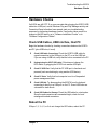
Chapter 3 - Troubleshooting the 82357A ............................................. 43
Troubleshooting Flowchart .......................................................... 45
Hardware Checks ........................................................................ 47
Contents 3
Check USB Cables, USB Interface, Host PC .......................47
Reboot the PC ......................................................................47
Check Device Manager .........................................................48
Software Installation Checks ........................................................49
Check Suspend/Resume Operation .....................................49
Verify Agilent IO Libraries Suite Installation ..........................49
Verify 82357A USB Driver Installation ..................................51
Software Configuration Checks ....................................................52
Checking IO Control Operation .............................................52
Check USB Scanner .............................................................53
Check for usbscan.sys (Windows 98 SE Only) .....................54
Service/Support Information .........................................................56
82357A Service Information ..................................................56
Contacting Agilent .................................................................56
Chapter 4 - 82357A User’s Guide Information .....................................57
Guide Contents.............................................................................59
Guide General Information ...........................................................60
Appendix A - 82357A Specifications ....................................................63
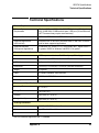
Technical Specifications ...............................................................65
Supplementary Information ..........................................................66
Index ........................................................................................................67
Contents 4
1
Installing the 82357A
Installing the 82357A
This Agilent 82357A USB/GPIB Interface Converter User’s Guide shows
how to install and configure the Agilent 82357A USB/GPIB Interface
Converter for PCs with Windows 98 (SE), Windows Me, Windows 2000,
or Windows XP Professional operating systems.
NOTE
The 82357A USB/GPIB Interface Converter is supported ONLY for PCs
with Windows 98 (Second Edition), Windows Me, Windows 2000, or
Windows XP Professional operating systems.
These operating systems are specifically not supported:
Windows 98 First (“Gold”) Edition
Windows 95
Windows NT 4.0 (OS does not support USB)
In case of difficulty in installing the 82357A, see Chapter 3 Troubleshooting the 82357A. See Chapter 4 - 82357A User Guide
Information for guide contents and general guide information.
This chapter shows suggested steps to install the 82357A, including:
6
Steps to Install the 82357A
Step 1: Before You Install the 82357A
Step 2: Installing the Agilent IO Libraries Suite
Step 3: Connecting the 82357A
Step 4: Configuring the 82357A
Step 5: Connecting GPIB Instruments
Step 6: Programming via the 82357A
Chapter 1
Installing the 82357A
Steps to Install the 82357A
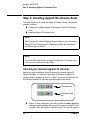
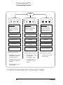
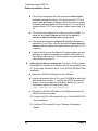
Steps to Install the 82357A
This figure shows a suggested sequence of steps to install and configure the
82357A and to communicate between your PC and GPIB instruments.
Step 1 - Before You Install the 82357A
Check Your Shipment
Check System Requirements
Step 2 - Installing Agilent IO Libraries Suite
Check for Installed Libraries
Install the Libraries
Step 3 - Connecting the 82357A
Connect to a USB Port
Observe Plug and Play Manager
Step 4 - Configuring the 82357A
Set default configuration OR
Set custom configuration
Step 5 - Connecting GPIB Instruments
Connect single GPIB instrument OR
Connect multiple GPIB instruments
Step 6 - Programming via the 82357A
Establish communication
Program GPIB instruments
Chapter 1
7
Installing the 82357A
Step 1: Before You Install the 82357A
Step 1: Before You Install the 82357A
Before you install the 82357A, you should:
Check Your Shipment
Check System Requirements
Check Your Shipment
Your 82357A USB/GPIB Interface Converter shipment should include the
items in the following figure. If any items are missing or damaged, keep the
shipping materials and contact Agilent Technologies. See “Contacting
Agilent” on page 56 for addresses and telephone numbers.
As you check the shipment items, verify that the 82357A Serial Number
on the bottom of the 82357A matches the Serial Number shown on the
Serial Number Label on the 82357A Kit Box and on the 82357A Certificate
of Calibration. If the Serial Numbers do not match, contact Agilent. If all
Serial Numbers match, you may want to record the Serial Number for future
reference.
Agilent Technologies 82357A USB/GPIB Interface Converter
Agilent Automation-Ready CD with Agilent IO Libraries Suite
82357A USB/GPIB Interface Converter Getting Started Poster
82357A USB/GPIB Interface Converter User's Guide
82357A Registration Card
Software License Agreement
Software License
Registration Card
82357A KIt Box
82357A Getting
Started Poster
US12345678
82357A USB/GPIB Interface
Converter
Serial Number Label
82357A User's
Guide
Agilent AutomationReady CD
8
Chapter 1
Installing the 82357A
Step 1: Before You Install the 82357A
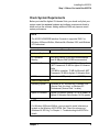
Check System Requirements
Before you install the Agilent IO Libraries Suite, you should verify that your
system meets the minimum hardware and software requirements listed to
install and use the software. Adding additional RAM may improve overall
system performance.
NOTE
The 82357A USB/GPIB Interface Converter is supported ONLY on
Windows 98 Second Edition, Windows Me, Windows 2000, and Windows
XP Professional.
Item
Minimum Requirements
Hardware Requirements
PC Operation/
Memory
200 MHz Pentium II (800 MHz recommended)
and 64 MBytes RAM (96 MB recommended).
Hard Drive Space
215 MB for installation: 160 MB for Microsoft
.NET Framework, 55 MB for Agilent IO Libraries
Suite
125 MB for operation: 70 MB for Microsoft .NET
Framework, 55 MB for Agilent IO Libraries Suite
USB Port
At least one USB port (to connect 82357A)
Software Requirements
Operating System
Windows 98 SE, Windows Me, Windows 2000
(Service Pack 4 or later), or Windows XP
Professional (Service Pack 1 or later).
Agilent IO Libraries
Agilent IO Libraries Version L.01.00 or greater, or
Agilent IO Libraries Suite Version 14.0 or greater.
NOTE
For Windows 98 Second Edition, you may need to install usbscan.sys,
located on the Windows 98 CD-ROM. See “Check for usbscan.sys
(Windows 98 SE Only)” in Chapter 3 - Troubleshooting the 82357A for
details.
Chapter 1
9
Installing the 82357A
Step 2: Installing Agilent IO Libraries Suite
Step 2: Installing Agilent IO Libraries Suite
This step shows how to install the Agilent IO Libraries Suite, using default
settings, including:
Checking for Installed Agilent IO Libraries or Agilent IO Libraries
Suite
Installing Agilent IO Libraries Suite
NOTE
See the Agilent IO Libraries Getting Started Guide on your AutomationReady CD for a full description of installation options and installation
troubleshooting information.
NOTE
You must have Administrator privileges to install the IO Libraries Suite
and to run the Connection Expert utility.
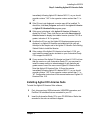
Checking for Installed Agilent IO Libraries
Before you begin installation, check for previously installed Agilent IO
Libraries software. If a version of the Agilent IO Libraries or Agilent IO
Libraries Suite is installed on your PC, a blue IO icon may be displayed on
the Windows taskbar (on the lower right-hand side of the screen).
IO Libraries icon
IO Libraries Suite
icon
If either IO icon is displayed, click the icon and click About Agilent IO
Libraries Control to display the version. The version must be L.01.00
or greater. Note that Agilent IO Libraries Suite 14.0 was the revision
10
Chapter 1
Installing the 82357A
Step 2: Installing Agilent IO Libraries Suite
immediately following Agilent IO Libraries M.01.01, so you should
consider revision “14.0” to be a greater version number than ”L” or
“M”.
If the IO icon is not displayed, a version may still be installed. To
check this, click Start | Programs and look for the Agilent IO Libraries
or Agilent IO Libraries Suite program group.
If this group is displayed, click Agilent IO Libraries | IO Control to
display the IO icon. Then, click the icon and click About Agilent IO
Libraries Control to display the installed version (must be L.01.00 or
greater, inclusive of 14.0 or greater).
If neither the IO icon nor the Agilent IO Libraries program group is
displayed, no Agilent IO Libraries are installed and you can use
the steps in this chapter and in the Agilent IO Libraries Suite Getting
Started Guide to install the libraries.
If the version of the Agilent IO Libraries is less than L.01.00, you
must install the newer version included on your Automation-Ready
CD to support the 82357A.
If your version of the Agilent IO Libraries is at least L.01.00, but less
than the version on your Automation-Ready CD, you may want to
install the newer version to take advantage of new features and
greater ease of use of the more recent Agilent IO Libraries Suite.
Note that Agilent IO Libraries Suite 14.0 was the revision
immediately following Agilent IO Libraries M.01.01, so you should
consider revision “14.0” to be a greater version number than “L” or
“M”. Configuration instructions in this manual make use of Agilent IO
Libraries Suite 14.0.
Installing Agilent IO Libraries Suite
To install the Agilent IO Libraries Suite software,
1
First, disconnect any USB instruments, USB/GPIB converters, and
FireWire-VXI interfaces that are connected to your PC.
2
Insert the Automation-Ready CD in your CD-ROM drive. Wait a few
seconds for the auto-run window to appear.
Chapter 1
11
Installing the 82357A
Step 2: Installing Agilent IO Libraries Suite
3
If the auto-run window does not appear automatically,
Click Start | Run...
Type <drive>:autorun\auto.exe, where <drive> is your
CD drive letter.
4
12
When the auto-run window appears, follow the directions in this
window to install the Agilent IO Libraries Suite. (See the Agilent IO
Libraries Getting Started Guide on your Automation-Ready CD for a
full description of installation options and installation troubleshooting
information.)
Chapter 1
Installing the 82357A
Step 3: Connecting the 82357A
Step 3: Connecting the 82357A
After the Agilent IO Libraries (Version L.01.00 or later) have been installed,
you can connect the 82357A to any USB port on your PC or you can connect
the 82357A via standard USB hubs. This step includes:
82357A Hardware Description
Connecting the 82357A to Your PC
Connecting the 82357A to a USB Hub
Observing Windows Plug and Play Manager (Windows XP)
NOTE
If the Agilent IO Libraries or Agilent IO Libraries Suite has not been
installed on your PC, STOP. Install the libraries (see Step 2: Installing the
Agilent IO Libraries Suite) and then return to this step.
NOTE
For Windows 98 Second Edition, you may need to install usbscan.sys,
located on the Windows 98 CD-ROM. See “Check for usbscan.sys
(Windows 98 SE Only)” in Chapter 3 - Troubleshooting the 82357A for
details.
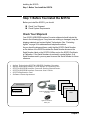
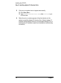
82357A Hardware Description
The Agilent 82357A USB/GPIB Interface Converter (82357A) provides a
direct interface connection from the USB port on your PC to GPIB
instruments. The 82357A includes an attached USB cable that is USB 1.1
compliant. This cable is shielded and the connector is specified for up to
1,500 insertions.
An 82357A can be directly connected to a single GPIB instrument or can
be connected to up to 14 GPIB instruments via GPIB cables. In addition,
several 82357As can be connected to your PC via standard USB hubs.
The following figure shows main 82357A hardware features.
Chapter 1
13
Installing the 82357A
Step 3: Connecting the 82357A
GPIB Connector.
Connect to up to 14
GPIB Instruments.
Green ACCESS LED
Green READY LED
Red FAIL LED
USB Cable. Connect
to USB Port.
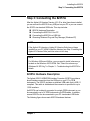
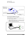
Connecting the 82357A to Your PC
This section shows steps to connect the 82357A to a USB port on your PC
or to connect to your PC via a USB Hub.
1
Connect to a USB Port. Make sure the PC is ON and plug the 82357A
USB cable into any available USB port on your PC. Do not connect
the 82357A to GPIB instruments at this time.
READY LED
Connect to USB Port
FAIL LED
82357A
USB Cable
ACCESS LED
14
Chapter 1
Installing the 82357A
Step 3: Connecting the 82357A
2
Observe the LEDs. Observe the LEDs on the 82357A for at least 10
seconds. See Chapter 2 - Using the 82357A for a description of the
normal LED sequence with an initial installation of an 82357A.
a Initially, only the red FAIL LED should be ON. After a few seconds,
all three LEDs should be ON. All three LEDs ON shows the
82357A has been successfully installed, but is not yet configured
for use with the Agilent IO Libraries Suite.
b If all three LEDs are not ON after 10 seconds and all Windows Plug
and Play Manager activity has ceased, STOP. See Chapter 3 Troubleshooting the 82357A for diagnostics information.
c
If all three LEDs are still ON after 10 seconds, go to “Observing
Windows Plug and Play Manager Sequence (Windows XP Only)”.
Connecting the 82357A to a USB Hub
This section shows steps to connect the 82357A to a USB port on your PC
via a standard USB hub.
NOTE
Any USB hub used with the 82357A MUST be self-powered (must not
be bus-powered or powered from the USB bus). Also, be sure to check
the applicable USB hub documentation for hub operating parameters,
such as power requirements and maximum length of USB cables.
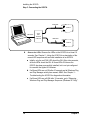
1
Plug the power adapter into the hub and into an electrical outlet.
Make sure the hub is operating in self-powered mode. For example,
the following figure shows a 4-port self-powered USB hub with two
82357A USB/GPIB Interface Converters connected.
2
Make sure your PC is ON. Connect the USB cable of the USB hub
to any available USB port on your PC.
3
Plug at least one 82357A USB/GPIB Interface Converter into the
port(s) on the USB hub. It is not necessary to connect GPIB
instruments to any 82357A at this time.
Chapter 1
15
Installing the 82357A
Step 3: Connecting the 82357A
USB Cable
82357A
USB Cable
4-Port
SelfPowered
USB Hub
USB Cable
82357A
4
Observe the LEDs. Observe the LEDs on the 82357A for at least 10
seconds. See Chapter 2 - Using the 82357A for a description of the
normal LED sequence with an initial installation of an 82357A.
a Initially, only the red FAIL LED should be ON. After a few seconds,
all three LEDs should be ON. All three LEDs ON shows the
82357A has been successfully installed, but is not yet configured
for use with the Agilent IO Libraries.
b If all three LEDs are not ON after 10 seconds and all Windows Plug
and Play Manager activity has ceased, STOP. See Chapter 3 Troubleshooting the 82357A for diagnostics information.
c
16
If all three LEDs are still ON after 10 seconds, go to “Observing
Windows Plug and Play Manager Sequence (Windows XP Only)”.
Chapter 1
Installing the 82357A
Step 3: Connecting the 82357A
Observing Windows Plug and Play Manager
Sequence (Windows XP Only)
When an 82357A is first plugged into a USB port, for Windows XP ONLY,
a Windows Plug and Play Manager installation sequence may be displayed.
NOTE
This section shows typical displays for a Windows XP Professional
operating system ONLY. Similar displays may appear for Windows
98 SE, Windows 2000, or Windows Me operating systems.
Introduction
The following sequence only appears when an 82357A is initially plugged
into a USB port. The sequence appears each time an 82357A with a new
serial number is installed or when an 82357A is installed in a new USB port.
For example, if an 82357A with Serial Number US12345678 is initially
plugged into USB port #1, the sequence may appear. If this 82357A is
configured using the sequence, the next time this 82357A is plugged into
USB port #1, the sequence will not appear.
However, if another 82357A is plugged into USB port #1 or if the 82357A
with Serial Number US12345678 is initially plugged into USB port #2, the
sequence may also appear.
NOTE
The displays in the following sequence assume you have installed the
Agilent IO Libraries Suite as shown in Step 2 - Installing Agilent IO
Libraries Suite. If you have not installed the libraries, STOP and do
Step 2 before continuing.
Chapter 1
17
Installing the 82357A
Step 3: Connecting the 82357A
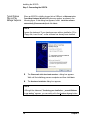
Typical Windows
Plug and Play
Manager Sequence
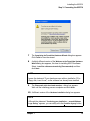
When an 82357A is initially plugged into a USB port, a Welcome to the
Found New Hardware Wizard dialog box may appear, as shown in the
following figure. If this dialog box appears, select Install the software
automatically (Recommended) and click Next>.
NOTE
Ignore the statement “If your hardware came with an installation CD or
floppy disk, insert it now”, as the software has already been installed.
5
The Please wait while the wizard searches... dialog box appears.
Wait until the initializing process completes and then click Next>.
6
The Hardware Installation dialog box appears.
NOTE
Although the statement “Continuing your installation ... passed Windows
Logo testing.” appears, you can safely click the Continue Anyway button.
18
Chapter 1
Installing the 82357A
Step 3: Connecting the 82357A
7
The Completing the Found New Hardware Wizard dialog box appears.
Click Finish to close the wizard.
8
A slightly different version of the Welcome to the Found New Hardware
Wizard dialog box appears, this time for installing 82357A software
Select Install the software automatically (Recommended) and then
click Next>.
NOTE
Ignore the statement “If your hardware came with an installation CD or
floppy disk, insert it now”, as the software has already been installed.
9
The Please wait while the wizard searches... dialog box appears.
Wait until the initializing process completes and click Next>.
10 A different version of the Hardware Installation dialog box appears.
NOTE
Although the statement “Continuing your installation ... passed Windows
Logo testing.” appears, you can safely click the Continue Anyway button.
Chapter 1
19
Installing the 82357A
Step 3: Connecting the 82357A
11 The Please wait while the wizard installs the software... dialog box
appears. After the installation is complete, click the Next> button to
display the Agilent 82357A USB/GPIB Interface Detected dialog box.
Go to “Step 4: Configuring the 82357A” to continue the installation.
20
Chapter 1
Installing the 82357A
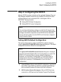
Step 4: Configuring the 82357A
Step 4: Configuring the 82357A
After the 82357A has been installed and the applicable Windows Plug and
Play Manager installation sequence has completed, the 82357A must be
configured before it can be used with SICL or with Agilent VISA or
VISA COM. This step includes:
Setting 82357A Default Configuration
Setting 82357A Custom Configuration
NOTE
You must have Administrator privileges to install the IO Libraries Suite
and to run the Connection Expert utility. If you do not have Administrator
privileges, the default configuration for the 82357A will not take effect,
and you will not be able to use the 82357A until it has been configured
using Connection Expert.
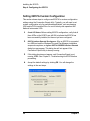
Setting 82357A Default Configuration
This section shows steps to configure an 82357A for default settings by
using the Agilent 82357A USB/GPIB Interface Detected dialog box. The default
configuration should be sufficient for most applications.
NOTE
The Agilent 82357A USB/GPIB Interface Detected dialog box is displayed
only if the Connection Expert utility is not running when you connect the
82357A. If Connection Expert is running, default configuration is
automatic; you need take no further action. (If Connection Expert is
running and you do not see your 82357A in the Connection Expert
window after connecting it, click Refresh All to force the default
configuration.)
1
Check LED Status. Before setting 82357A configuration, verify that all
three LEDs on the 82357A are still ON to indicate the 82357A has
been successfully installed, but has not yet been configured.
2
82357A Interface Detected Box Appears. After an 82357A has been
connected to a USB port and the Windows Plug and Play Manager
Chapter 1
21
Installing the 82357A
Step 4: Configuring the 82357A
installation sequence has completed, an Agilent 82357A USB/GPIB
Interface Detected dialog box should appear.
3
If the Agilent 82357A USB/GPIB Interface Detected dialog box does not
appear, and the Connection Expert utility is not running, STOP. See
Chapter 3 - Troubleshooting the 82357A before continuing.
NOTE
Connecting Multiple 82357As. An Agilent 82357A USB/GPIB
Detected dialog box should appear each time you plug an 82357A into
a USB port. For example, if you plug three 82357As into USB ports, three
dialog boxes should appear. Each dialog box will remain until you remove
it by clicking OK (or the x box). These dialog boxes will only appear if
Connection Expert is not running.
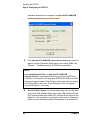
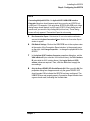
4
Record VISA/SICL Names. For future programming use, you will need
to know the VISA Interface Name (also called VISA interface ID) and
SICL Interface Name (also called SICL interface ID) as shown on the
dialog box. You may want to record these values now. In Connection
Expert, you can see these interface IDs displayed in the detail pane
22
Chapter 1
Installing the 82357A
Step 4: Configuring the 82357A
(right pane of the Connection Expert window) when you highlight the
USB/GPIB interface.
5
VISA Interface ID
_______________________________
SICL Interface ID
_______________________________
Accept Default Settings. Click OK (or click the x box) to configure the
82357A with the (default) settings for the VISA Interface Name and
the SICL Interface Name shown in the dialog box. If you do not want
to accept the default settings, see the next section “Setting 82357A
Custom Configuration.”
6
Only the READY LED Should Remain ON. After you click OK (or click
the x box), the dialog box disappears and only the green READY
LED should remain ON to indicate the 82357A has been configured.
7
Configure Multiple 82357A Interface Converters. If you have more than
one 82357A in your system, repeat 1 - 6 for each additional interface
converter.
NOTE
At any time after the Agilent IO Libraries Suite is installed, you can
reconfigure an 82357A by clicking the blue IO icon and clicking
Agilent Connection Expert.
Chapter 1
23
Installing the 82357A
Step 4: Configuring the 82357A
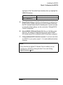
Setting 82357A Custom Configuration
This section shows steps to configure an 82357A for custom configuration
settings using the Connection Expert utility. Typically, you will need to set
custom configuration only for specialized applications, such as changing
VISA and/or SICL interface IDs or for use in side-by-side operation with
National Instruments VISA.
1
Check LED Status. Before setting 82357A configuration, verify that all
three LEDs on the 82357A are still ON to indicate the 82357A has
been successfully installed, but has not yet been configured.
2
82357A Interface Detected Box Appears. After an 82357A is connected
to a USB port and the Windows Plug and Play Manager installation
sequence completes, an Agilent 82357A USB/GPIB Interface Detected
dialog box may appear. This dialog box will not appear if the
Connection Expert utility is already running.
3
If this dialog box does not appear, and Connection Expert is not
running, STOP. See Chapter 3 -Troubleshooting the 82357A before
proceeding.
4
Accept the default settings by clicking OK. You will change the
settings in the next steps.
24
Chapter 1
Installing the 82357A
Step 4: Configuring the 82357A
NOTE
Connecting Multiple 82357As. An Agilent 82357A USB/GPIB Interface
Detected dialog box should appear each time you plug an 82357A into
a USB port. For example, if you plug three 82357As into USB ports, three
dialog boxes should appear, one for each 82357A. Each dialog box will
remain until you remove it by clicking OK (or the x box). These dialog
boxes will only appear if Connection Expert is not running.
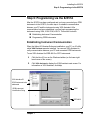
5
Run Connection Expert. Click the blue IO icon in the taskbar notification
area and click Agilent Connection Expert. Wait for the Connection Expert
window to appear.
6
Edit Default Settings. Click on the USB/GPIB icon in the explorer view
at the center of the Connection Expert window. In the property pane
on the right, click Change Properties... to change the properties for the
82357A.
7
In the Agilent 82357 Interface Converter properties dialog box, set the
VISA interface ID (also called the VISA Interface Name), the SICL interface
ID (also called the SICL Interface Name), the Logical Unit and GPIB
address values as required. Then, click the OK button to apply the
new settings.
8
Only the Green READY LED Should Remain ON. After you click OK, the
properties dialog box disappears and only the green READY LED
should remain ON to indicate the 82357A has been configured. The
USB/GPIB icon and property pane in Connection Expert should show
a green check mark, indicating the Verified state.
Chapter 1
25
Installing the 82357A
Step 4: Configuring the 82357A
9
Record VISA/SICL Names. For future programming use, you will need
to know the VISA interface ID and SICL interface ID as shown in the
properties pane. After you finish editing the 82357A configurations,
you may want to record these values. You can see these values at
any time by running Connection Expert and selecting the USB/GPIB
interface.
VISA Interface ID
_______________________________
SICL Interface ID
_______________________________
10 Configure Multiple 82357A Interface Converters. If you have more than
one 82357A in your system, repeat 6- 9 for each additional interface
converter.
NOTE
At any time after the Agilent IO Libraries Suite is installed, you can
configure an 82357A by clicking the blue IO icon and clicking Agilent
Connection Expert.
26
Chapter 1
Installing the 82357A
Step 5: Connecting GPIB Instruments
Step 5: Connecting GPIB Instruments
After the 82357A has been installed and configured, the next step is to
connect GPIB instruments to the 82357A. This step includes:
Connecting a Single GPIB instrument
Connecting Multiple GPIB Instruments
CAUTION
To avoid damage to the connectors, only finger-tighten the connectors.
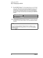
Connecting a Single GPIB Instrument
The following figure shows connection from a single GPIB instrument to
the GPIB port on an 82357A. When you have made the connection for
your system, go to “Step 6: Programming via the 82357A”. You may want
to record the primary GPIB address of the attached instrument for future
programming use.
82357A GPIB Connector
GPIB Port
USB Cable
To USB Port
on PC or on
USB Hub
82357A
Chapter 1
GPIB Instrument
GPIB Instrument
27
Installing the 82357A
Step 5: Connecting GPIB Instruments
Connecting Multiple GPIB Instruments
The following figure shows a typical way to connect three GPIB
instruments to an 82357A. When you have made the connections for
your system, go to “Step 6: Programming via the 82357A”.You may want
to record the primary GPIB address of each attached instrument for future
programming use
NOTE
Although the figure shows 82357A connection to GPIB Instrument 1,
the connection can be to any GPIB instrument in the system. Be sure
to first connect the GPIB cable to the GPIB instrument and then
“piggy-back” the 82357A GPIB connector to the GPIB cable.
82357A GPIB Connector
GPIB Cable Connector
USB Cable
82357A
GPIB
GPIBInstrument
Instrument1
To USB Port
on PC or on
USB Hub
GPIB Cables
GPIB
Instrument2 2
GPIB
Instrument
GPIB
Instrument3 3
GPIB
Instrument
28
Chapter 1
Installing the 82357A
Step 6: Programming via the 82357A
Step 6: Programming via the 82357A
After the 82357A has been configured and you have connected your GPIB
instruments to the 82357A, the next step is to establish communication
between your PC and the instruments using VISA Assistant. After
communication has been established, you can begin programming the
instruments using VISA, VISA COM, or SICL. This section includes:
Establishing Instrument Communication
Programming GPIB Instruments
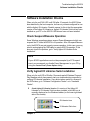
Establishing Instrument Communication
When the Agilent IO Libraries Suite was installed on your PC, an IO utility
called VISA Assistant was also installed. You can use VISA Assistant to
verify communication between your PC and connected GPIB instruments.
To use VISA Assistant for IEEE-488.2 or SCPI instruments:
1
Click the blue IO icon on the Windows taskbar (on the lower righthand corner of the screen).
2
Click VISA Assistant to display the VISA Assistant main screen. For
information on VISA Assistant, click Help.
VISA Interface ID
GPIB Instrument to be
addressed
GPIB Instrument
Identification String
*IDN?
IEEE 488.2
Chapter 1
29
Installing the 82357A
Step 6: Programming via the 82357A
3
Highlight the GPIB instrument to be addressed.
4
Select the Formatted I/O Tab.
5
Select the IEEE 488.2 button.
6
Click the *IDN? button.
7
The GPIB Instrument String should appear.
8
Repeat Steps 3 - 8 for the next GPIB instrument.
9
When communication has been established with each GPIB
instrument, you can begin to program the instruments using VISA,
VISA COM, or SICL. See the next section, “Programming GPIB
Instruments”, for an introduction.
Programming GPIB Instruments
This section provides an introduction to programming GPIB instruments via
the 82357A USB/GPIB Interface Converter using the Agilent VISA,
VISA COM, and SICL IO Libraries. You can program in various languages/
applications, including Visual Basic, Visual C++, Agilent VEE, and National
Instruments LabVIEW.
See the applicable User’s Guide, such as the Visual Basic User’s Guide,
for programming guidelines. You can also find additional programming
examples using various IO Libraries and instrument drivers in the instrument
User’s Guide. After the 82357A is successfully installed and configured, the
Interface Converter acts as a transparent interface for programming GPIB
instruments.
For information on programming using Agilent VISA, see the Agilent VISA
User’s Guide. For information on VISA COM and for function references for
VISA, VISA COM, and SICL, see the IO Libraries Suite Online Help.
30
Chapter 1
Installing the 82357A
Step 6: Programming via the 82357A
Accessing VISA and You can access .pdf copies of the Agilent VISA User’s Guide and the
SICL Manuals
Agilent SICL User’s Guide for Windows from the blue IO icon on the
Windows taskbar. Adobe Reader is required to view these manuals.
To access the Agilent VISA User’s Guide, click the IO icon and then click
Documentation | VISA Users Guide. To access the Agilent SICL User’s Guide
for Windows, click the IO icon and then click Documentation | SICL Users
Guide. To access VISA COM information, and function references for VISA,
VISA COM, and SICL, click the IO icon and then click Documentation | IO
Libraries Suite Help.
Introduction to IO
Interface
Configuration
An IO interface consists of a hardware interface and a software interface.
One purpose of the Connection Expert utility is to associate a unique
software interface ID with a hardware interface.
The Agilent IO Libraries Suite uses an Interface ID or Logical Unit Number to
identify an interface. This information is passed in the parameter string of
the viOpen function call in a VISA program or in the iopen function call in
a SICL program.
Connection Expert assigns an Interface ID and Logical Unit (LU) Number to
the interface hardware, as well as other necessary configuration values for
an interface when the interface is configured. Typically, the LU Number is
automatically assigned and you can ignore its setting. The LU Number is
used internally as a unique identifier. When the IO interface is configured,
you can use Agilent VISA, VISA COM, or SICL to program assigned
instruments.
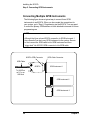
Example: IO
Interface
Configuration
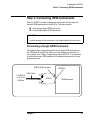
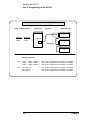
For example, the GPIB interface system in the following figure consists of
a Windows PC with an 82357A USB/GPIB Interface Converter connected
between a USB port and three GPIB instruments with GPIB primary
addresses of 3, 4, and 5, respectively. The instruments are connected via
GPIB cables.
For this system, the Connection Expert utility has been used to assign a
VISA name of “GPIB1” and a SICL name of “hpib7”. With these names
assigned to the interfaces, the VISA/SICL addressing is as shown in the
figure.
Since unique names have been assigned by Connection Expert, you can
use the VISA viOpen command to open the IO paths to the GPIB
instruments as shown in the figure. Or, you can use the SICL iopen
command to open the IO paths.
Chapter 1
31
Installing the 82357A
Step 6: Programming via the 82357A
Typical System Installation - 82357 USB/GPIB Interface
Interface VISA/SICL Names
Windows PC
USB Cable
GPIB Instruments
82357A
VISA Name
5
SICL Name
USB Port
"GPIB1"
"hpib7"
4
GPIB Cables
3
VISA/SICL Addressing
VISA:
viOpen (... "GPIB1::5::INSTR"...)
viOpen (... "GPIB1::4::INSTR"...)
viOpen (... "GPIB1::3::INSTR"...)
Open IO path to GPIB instrument at address 5 using 82357
Open IO path to GPIB instrument at address 4 using 82357
Open IO path to GPIB instrument at address 3 using 82357
SICL:
iopen ("hpib7,5")
iopen ("hpib7,4")
iopen ("hpib,3")
Open IO path to GPIB instrument at address 5 using 82357
Open IO path to GPIB instrument at address 4 using 82357
Open IO path to GPIB instrument at address 3 using 82357
32
Chapter 1
2
Using the 82357A
Using the 82357A
This chapter describes normal operating states for the 82357A and gives
guidelines to use the 82357A including:
Modes of Operation
Setting Configuration Parameters
34
Chapter 2
Using the 82357A
Modes of Operation
Modes of Operation
This section describes normal operational modes for the 82357A, including:
Initial 82357A Operating States
Introduction to 82357A Operating Modes
Single 82357A Operation
Multiple 82357A Operation
SRQ Operation
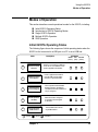
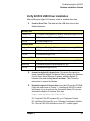
Initial 82357A Operating States
The following figure shows the sequence of initial operating states when the
82357A is first connected to a USB port on a PC or on a USB hub.
State
Description
82357A Connected,
No Power
2
82357A Connected,
Power Applied
3
82357A Installed
but not Configured
Host computer has downloaded
startup firmware to the 82357A.
The 82357A has been installed but
not yet configured.
4
Normal Operation,
Idle State
82357A has been configured
for operation with the Agilent
IO Libraries.
5
Normal Operation,
GPIB Transfers
The ACCESS LED is ON for
any GPIB transfers.
LED ON
Chapter 2
FAIL
ACCESS
(Green)
(Red)
(Green)
82357A is connected to a USB port
on the PC or on a USB hub, but no
power is applied to the 82357A.
1
LED OFF
LED States
READY
Power is applied to the 82357A
from the USB port, but startup
firmware not yet downloaded.
Intermittent
35
Using the 82357A
Modes of Operation
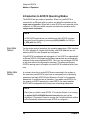
Introduction to 82357A Operating Modes
The 82357A has two modes of operation. When only one 82357A is
connected to a USB port within a system, we define the operation as the
single mode of operation. When two or more 82357As are connected at the
same time to USB ports within a system, we define the operation as the
multiple mode of operation.
NOTE
All SICL/VISA applications are notified when their 82357A has been
removed from the system by returning VI_ERR_NOINFC (for VISA) or
I_ERR_NCIC (for SICL).
Single Mode
Features
For the single mode of operation, the operating parameters (VISA Interface
ID, SICL Interface ID, Logical Unit Number, and GPIB Address) are set
when the 82357A is first installed and configured.
If this 82357A is unplugged and replugged or if the 82357A is replaced with
a different 82357A, the original configuration parameters are automatically
assigned to the newly attached 82357A. Thus, you can exchange 82357As
at any time without reconfiguring the interface. This allows exchanging
82357As among users, as long as only one 82357A is attached at any one
time.
Multiple Mode
Features
In contrast, when two or more 82357As are connected to the system at
the same time, each 82357A must have its own specific set of operating
parameters and each 82357A Serial Number is “bound” to its operating
parameters. In multiple mode of operation, if you add a new 82357A or if
you unplug an 82357A and plug in a new 82357A, the newly installed
82357A will be assigned a new (unique) set of operating parameters.
NOTE
Each time you attach a new 82357A, if Connection Expert is not running,
an Agilent 82357A USB/GPIB Interface Detected dialog box will be
displayed. If Connection Expert is running, the Connection Expert window
will automatically refresh as the new 82357A is configured.
36
Chapter 2
Using the 82357A
Modes of Operation
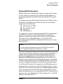
Single 82357A Operation
When an 82357A is first installed and configured, a default VISA Interface
ID, SICL Interface ID, Logical Unit (LU) number and GPIB Address are
automatically assigned to the Serial Number associated with this specific
82357A.
For example, assume an 82357A with Serial Number US12345678. When
this 82357A is first installed, typical values as shown are automatically
assigned to this Serial Number.
VISA Interface ID: GPIB0
SICL Interface ID: hpib7
Logical Unit: 7
GPIB Address: 21
For single mode of operation, when the existing 82357A is removed and a
new 82357A is installed, the new 82357A assumes all configuration
attributes of the previously configured 82357A (same VISA Interface ID,
SICL Interface ID, LU and GPIB Address). Thus, any SICL/VISA
applications using that VISA/SICL configuration will continue to run using
the new 82357A.
NOTE
You can change the parameter values of the 82357A as required.
See “Changing Configuration Parameters” for details.
The first time an 82357A is attached to a system (assuming the Agilent IO
Libraries Suite is installed), the software recognizes that an 82357A is
attached. If Connection Expert is not running, the software displays an
Agilent 82357A USB/GPIB Interface Detected dialog box that allows you to
accept the current settings. If Connection Expert is running, it automatically
refreshes, displaying the 82357A as a USB/GPIB interface in its tree view;
you can then change the properties of the interface in Connection Expert.
The VISA and SICL interface IDs, Logical Unit, and GPIB Address may be
viewed at any time in the property pane of the Connection Expert. (To view
this window, click the blue IO icon and then click Agilent Connection Expert.)
Then, if you disconnect this 82357A and plug in another 82357A (with a
different Serial Number) or if you re-plug the same 82357A, the new 82357A
will assume the same VISA Interface ID, SICL Interface ID, LU, and GPIB
Address as the original 82357A.
Chapter 2
37
Using the 82357A
Modes of Operation
Multiple 82357A Operation
When two or more 82357As are attached to a system at the same time,
we define the mode as the multiple mode of operation. In multiple mode of
operation, each 82357A is “bound” to its related IO Configuration for that
Serial Number. This is a different mode of operation than the single mode of
operation in that the configuration is not reused if you replace an 82357A
with another 82357A.
As with single mode of operation, the first time an 82357A is attached to a
system (assuming the Agilent IO Libraries Suite is installed), the software
recognizes that an 82357A is attached. If Connection Expert is not running,
the software displays an Agilent 82357A USB/GPIB Interface Detected dialog
box that allows you to accept the current settings. If Connection Expert is
running, it automatically refreshes, displaying the 82357A as a USB/GPIB
interface in its tree view; you can then change the properties of the interface
in Connection Expert.
The VISA and SICL interface IDs, Logical Unit, and GPIB Address may be
viewed at any time in the property pane of the Connection Expert. (To view
this window, click the blue IO icon and then click Agilent Connection Expert.)
Then, if you plug in another 82357A (with a different Serial Number), the
new 82357A will automatically be assigned a unique VISA Interface ID, SICL
Interface ID, LU, and GPIB Address.
NOTE
You can change the parameter values of the 82357A as required. See
“Changing Configuration Parameters” for details.
You can also convert from multiple mode of operation to single mode of
operation. See “Changing Modes of Operation” for details.
SRQ Operation
If your VISA/SICL application uses SRQ callbacks (viEventHandler() in VISA
or ionsrq() in SICL) and your callback does not service the SRQ in a timely
manner, your SRQ callback function may be called multiple times.
To avoid this possible situation, design your SRQ callback functions to
handle being called when an SRQ is no longer asserted on the GPIB bus.
38
Chapter 2
Using the 82357A
Setting Configuration Parameters
Setting Configuration Parameters
This section gives guidelines to change or set various configuration
parameters for the 82357A, including:
Changing Configuration Parameters
Changing Modes of Operation
Setting Timeout Floor Value
Setting High-Performance Operation
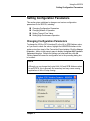
Changing Configuration Parameters
To change the VISA or SICL Interface ID or the LU or GPIB Address value,
or if you want to check the values, highlight the USB/GPIB interface in the
explorer view (tree view) of the Connection Expert window. Click the Change
Properties... button in the property pane to display the Agilent 82357 Interface
Converter dialog box. Choose the settings you want and then click OK.
Clicking Cancel will cause the configuration set in the preceding dialog box
to be used..
NOTE
Although you can change the Logical Unit (LU) and GPIB Address values
for an 82357A, this is generally not necessary and may cause running
applications to fail or to stop running.
Chapter 2
39
Using the 82357A
Setting Configuration Parameters
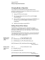
Changing Modes of Operation
If your system has multiple 82357As configured (multiple mode of
operation), the only way to change from multiple mode of operation back to
the single mode of operation is:
1
Unplug all 82357As from the system.
2
Run Connection Expert (click the blue IO icon and click Agilent
Connection Expert).
3
Delete all 82357A configurations by selecting each USB/GPIB icon in
the explorer view and clicking Delete (or delete all except one
configuration).
4
Reattach and reconfigure a single 82357A.
Setting Timeout Floor Values
The 82357A has a default timeout “floor” value that is an internal
requirement to ensure reliable USB communication. The 82357A will not
allow timeouts LESS than the floor value. (By default, VISA/SICL timeouts
are set to an infinite time.)
To programmatically determine the timeout floor, you can set the timeout to
a very small value, such as 1 msec, and then query for the actual timeout
floor value. VISA and SICL examples follow.
Example: Query
Timeout Floor
(VISA)
tval = 1;
// Try to set timeout to 1 msec
err = viSetAttribute(id, VI_ATTR_TMO_VALUE, tval_in);
...
err = viGetAttribute(id, VI_ATTR_TMO_VALUE, &tval_out);
...
printf("Set timeout to [%d], actual timeout that resulted [%d]\n",
tval_in, tval_out );
Example: Query
TimeOut Floor
(SICL)
tval = 1;
// Try to set timeout to 1 msec
err = itimeout(id, tval_in);
...
err = igettimeout(id, &tval_out);
...
printf("Set timeout to [%d], actual timeout that resulted [%d]\n",
tval_in, tval_out );
40
Chapter 2
Using the 82357A
Setting Configuration Parameters
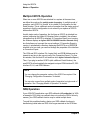
Setting 82357A High-Performance Operation
NOTE
Changing the T1 delay as described in this section is an advanced
feature and also requires attention to cable lengths and other system
features.
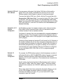
Introduction
The GPIB transfer rate for 82357A writes using large (>1000 bytes) buffer
size is affected by the Data Available (T1) delay time. (The transfer rates are
not noticeably affected when the buffer size is <1000 bytes). The default
delay time used by the 82357A is 800 nsec.
The maximum transfer rate for T1 = 350 nsec is about 900 KBytes/sec as
compared to about 650 KBytes/sec for the 82357A default value of 800
nsec. Changing the T1 delay affects ONLY the write performance of the
82357A.
Setting T1 Value
With VISA
To set the T1 value with VISA, use the VI_AGATTR_GPIB_T1_DELAY
attribute. The VI_AGATTR_GPIB_T1_DELAY value is the time of the T1 delay in
nanoseconds, and should be no less than VI_AG_GPIB_T1DELAY_MIN
or no greater than VI_AG_GPIB_T1DELAY_MAX. This value is defined in
Agilent's 'visa.h' header file. To use this value, you must '#define
AGVISA_ATTRIBUTES' before the '#include "visa.h" in your C or C++ source
file.
The 82357A supports T1 delays from 350 nsec to <max_value> in steps of
40 nsec. You can find out the actual value by calling viGetAttribute().
Attribute
VI_AGATTR_GPIB_
T1_DELAY
Setting T1 Value
With SICL
Access Priv. Data Type
RW Global
ViInt32
Range (nsec)
VI_AG_GPIB_T1DELAY_MIN to
VI_AG_GPIB_T1DELAY_MAX
Used By
GPIB INTFC
resources
To set the T1 value with SICL, use the igpibsett1delay() command and
modify the GPIB environment. For further information, you may want
to see the Hewlett-Packard document “Tutorial Description of the HewlettPackard Interface Bus”. See Section 2.12, Optimizing Performance.
Chapter 2
41
Using the 82357A
Setting Configuration Parameters
Notes:
42
Chapter 2
3
Troubleshooting the 82357A
Troubleshooting the 82357A
This chapter provides troubleshooting guidelines and service/support
information for the Agilent 82357A USB/GPIB Interface Converter.
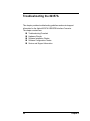
The chapter contents are:
44
Troubleshooting Flowchart
Hardware Checks
Software Installation Checks
Software Configuration Checks
Service and Support Information
Chapter 3
Troubleshooting the 82357A
Troubleshooting Flowchart
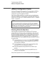
Troubleshooting Flowchart
The figure on the next page shows a suggested sequence of steps to
diagnose and troubleshoot 82357A problems, based on the LED states.
You can use the LED states to help diagnose and troubleshoot the 82357A
whenever the LED states do not match expected normal states. See
Chapter 2 - Using the 82357A for the normal LED sequence when the
82357A is initially connected to a USB port.
Observe the LED
States
To begin troubleshooting, determine the LED states after at least 10
seconds have elapsed since the 82357A was connected to a USB port and
all Windows Plug and Play Manager activity has ceased. Then:
If all LEDs are OFF, start with “Hardware Checks”
If the red FAIL LED is ON, start with “Software Installation Checks”
If all LEDs are ON, start with “Software Configuration Checks”
After taking the steps in the check sequence, use the boxes at the bottom
of the chart to determine the next step. For example, if doing a Hardware
Check results in only the red FAIL LED remaining ON, go to “Software
Installation Checks”, etc.
NOTE
You do not have to do all the steps or do the steps in the order shown.
If any action results in a change in LED states, go to the applicable check
sequence to continue troubleshooting.
Chapter 3
45
Troubleshooting the 82357A
Troubleshooting Flowchart
START
All LEDs OFF
READY
FAIL
Red FAIL LED ON
ACCESS
READY
FAIL
All LEDs ON
ACCESS
READY
FAIL
ACCESS
Typical Cause
Typical Cause
Typical Cause
No power on USB bus
or device turned off by
W indows Plug and Play
Manager.
Agilent IO Libraries not
installed or 82357A USB
drivers not installed.
Im proper Agilent IO
Libraries configuration
or m issing usbscan.sys
(W indows 98 SE only)
Hardw are Checks
Softw are Installation
Checks
Softw are Configuration
Checks
Check Cables, USB
Interface, Host PC
Check Suspend/Resum e
Operation
Check IO Control
O peration
Reboot PC
Verify Agilent IO Libraries
Installation
Check USB Scanner
Check Device Manager
Verify Driver Installation
Check for usbscan.sys
(W indows 98 SE O nly)
After Doing These Checks:
After Doing These Checks:
After Doing These Checks:
y
If the FAIL LED is the only
LED ON, go to Software
Installation Checks.
y
If all three LEDs are ON,
go to Software
Configuration Checks.
y
If all three LEDs are ON, go
to Software Configuration
Checks.
y
If the FAIL LED is the
only LED ON, contact
Agilent.*
y
If all three LEDs are OFF,
contact Agilent.*
y
If all three LEDs are ON,
contact Agilent.*
*For telephone and web assistance, see “Contacting Agilent” on page 56.
46
Chapter 3
Troubleshooting the 82357A
Hardware Checks
Hardware Checks
If all LEDs are still OFF 10 or more seconds after plugging the 82357A USB
cable into a USB port, and all Windows Plug and Play Manager activity and
Connection Expert refreshes have ceased, start your troubleshooting
sequence by performing hardware checks. If any action taken results in a
change in the LED status, go to “Software Installation Checks” or to
“Software Configuration Checks”.
Check USB Cables, USB Interface, Host PC
Begin the hardware checks by checking connections between the 82357A
and PC (plus USB hubs, if used).
1
Check USB Cable Connections. Check the 82357A USB cable for
a good connection to the USB port on the PC or on the USB hub.
If you are using a USB hub, verify that the hub is connected to the PC.
2
Unplug/replug the 82357 USB cable. If this does not change the
LED status, try plugging the 82357A into another USB port.
3
Check PC USB Port. Verify that the PC USB port is functional and
powered (such as checking by using another USB device).
4
Check PC State. Verify that host computer is not in a Suspended
power management state.
5
Check USB Hub. Try disconnecting the 82357A from the hub and
connecting it directly to a USB port on the PC. Some USB hubs are
vulnerable to static shock.
6
Check USB Cables for Damage. Check the USB cable for cuts/crushes.
Since the end connectors are somewhat fragile, check for bent/
misaligned/crushed connectors.
Reboot the PC
If Steps 1, 2, 3, 4, 5, or 6 do not change the LED status, reboot the PC.
Chapter 3
47
Troubleshooting the 82357A
Hardware Checks
Check Device Manager
You can use the Windows Device Manager to reinstall the 82357A, as
required. For example, with Windows 2000, go to Control Panel by selecting
Start | Settings | Control Panel.
Then, select System | Hardware | Device Manager. From Device Manager,
select 82357 and then Properties. Tab to Driver and click Reinstall Driver.
This will allow the Windows Plug and Play Manager to begin searching for a
driver for the 82357A. Since Device Manager may have disabled the 82357A
USB device, click Enable to restart the 82357A.
NOTE
If you are using a USB scanner, scanner conflicts are possible. See
“Check USB Scanner” in the Software Configuration Checks section.
48
Chapter 3
Troubleshooting the 82357A
Software Installation Checks
Software Installation Checks
When only the red FAIL LED is still ON after 10 seconds, the 82357A has
been detected by the host computer, but has not yet been configured for use
with the Agilent IO Libraries. Possible causes for this is that the appropriate
version of the Agilent IO Libraries or Agilent IO Libraries Suite has not been
installed on your PC or the 82357A USB drivers have not been installed.
Check Suspend/Resume Operation
Some Windows operating systems support Power Management which can
suspend the PC while the 82357A is in operation. After a Suspend/Resume
cycle, the 82357A may not properly resume operation. In this case, you may
need to unplug/replug the USB cable to restore 82357A operation. If this
does not correct the problem, go to “Verify Agilent IO Libraries Suite
Installation”.
NOTE
If your 82357A applications must not be preempted by a PC Suspend
event, we recommend you disable Power Management on your PC by
using the Control Panel | Power Options dialog.
Verify Agilent IO Libraries Suite Installation
When only the red LED is ON after 10 seconds and all Windows Plug and
Play Manager activity has ceased, start your troubleshooting sequence by
verifying IO Libraries installation. If any action taken results in a change in
the LED status, go to “Software Configuration Checks” or to “Hardware
Checks”.
1
Check Agilent IO Libraries Version. If a version of the Agilent IO
Libraries or IO Libraries Suite has been installed, a blue IO icon is
normally displayed on the Windows taskbar (on the lower right-hand
side of the screen).
IO Libraries Icon
IO Libraries Suite Icon
Chapter 3
49
Troubleshooting the 82357A
Software Installation Checks
a If the IO icon is displayed, click the icon and click About Agilent
IO Control to display the version. The version must be L.01.00 or
greater. Note that Agilent IO Libraries Suite 14.0 was the revision
immediately following Agilent IO Libraries M.01.01, so you should
consider revision “14.0” to be a greater version number than ”L” or
“M”.
b If the IO icon is not displayed, a version may still be installed. To
check this, click Start | Programs and look for the Agilent IO
Libraries or Agilent IO Libraries Suite program group.
c
If this group is displayed, click Agilent IO Libraries | IO Control to
display the IO icon. Then, click the icon and click About Agilent IO
Libraries Control to display the installed version (must be L.01.00
or greater).
d If neither the IO icon nor the Agilent IO Libraries program group is
displayed, no Agilent IO Libraries are installed. In this case, or if
the installed version is not L.01.00 or greater, you must install the
newer version (see Step 2).
2
Install Agilent IO Libraries (as Required). If Version L.01.00 or greater
of the Agilent IO Libraries or IO Libraries Suite is not installed on your
PC, use this step. Otherwise, skip to “Verify 82357A USB Driver Files
Installation”.
a Remove the 82357A USB cable from the USB port.
b Insert the Automation-Ready CD in your CD-ROM drive and follow
the instructions in Chapter 1 - Installing the 82357A to install the
libraries. If you do not have the Automation-Ready CD, you can
download the Agilent IO Libraries Suite from
http://www.agilent.com/find/iolib
c
Re-attach the 82357A USB cable to the USB port and check the
LEDs for at least 10 seconds.
If only the red FAIL LED remains ON, go to “Verify 82357A USB
Driver Installation”.
If all three LEDs remain ON, go to “Software Configuration
Checks”.
50
Chapter 3
Troubleshooting the 82357A
Software Installation Checks
Verify 82357A USB Driver Installation
After installing the Agilent IO Libraries, check for installed driver files.
1
Check for Driver Files. This table lists the USB driver files in their
default directories.
Windows 2000
Program Files
C:\Program Files\Agilent\IO Libraries Suite\drivers\ag357i32.dll
Driver Files
C:\Winnt\system32\drivers\agt82357.sys
.inf Files
C:\Winnt\inf\agt357.inf
Windows Me/XP
Program Files
C:\Program Files\Agilent\IO Libraries Suite\drivers\ag357i3l.dll
Driver Files
C:\Windows\system32\drivers\agt82357.sys
.inf Files
C:\Windows\inf\agt357.inf
Windows 98 SE
Program Files
C:\Program Files\Agilent\IO Libraries Suite\drivers\ag357i3l.dll
Driver Files
C:\Windows\system32\drivers\agt82357.sys
.inf Files
C:\Windows\inf\agt3579x.inf
2
Uninstall the Agilent IO Libraries Suite. If the driver files cannot be
found, uninstall the Agilent IO Libraries Suite by going to the Windows
Control Panel, Add or Remove Programs, selecting Agilent IO
Libraries Suite, and clicking Remove and Next>. Then, follow the
instructions to remove the libraries.
3
Reinstall the Agilent IO Libraries Suite. Insert the CD into the CD-ROM.
Follow the instructions in Chapter 1 - Installing the 82357A to install
the libraries. If you do not have the Automation-Ready CD, you can
download the Agilent IO Libraries Suite from
http://www.agilent.com/find/iolib
If only the FAIL LED remains ON, go to “Hardware Checks”.
If all three LEDs turn ON, go to “Software Configuration Checks”.
If the red FAIL LED still does not turn OFF, contact Agilent.
Chapter 3
51
Troubleshooting the 82357A
Software Configuration Checks
Software Configuration Checks
If all three LEDs remain ON for more than 10 seconds after the 82357A is
connected to a USB port, the 82357A has been installed but is not yet
configured for use with the Agilent IO Libraries.
When all three LEDs are ON after 10 seconds, start your troubleshooting
sequence by checking IO Control operation. If any action taken results in a
change in the LED status, go to “Software Installation Checks” or “Hardware
Checks”, as applicable.
NOTE
If you are using the 82357A with Windows 98 (SE), before beginning
these checks verify that your operating system is Windows 98 (SE), not
Windows 98, First (“Gold”) Edition. The 82357A will not operate correctly
for a Windows 98, First Edition operating system.
Checking IO Control Operation
When the Agilent IO Libraries Suite was installed, an IO Control was
created. When the IO Control is active, it is displayed as a blue IO icon on
the Windows taskbar. By default, the IO Control is always active after the
libraries are installed and the blue IO icon is displayed. However, if the IO
Control is deactivated, SICL/VISA applications that are running with the
82357A will malfunction. Some symptoms that may occur when IO Control is
not active include:
Connection Expert is not running, but an Agilent 82357A USB/GPIB
Interface Detected dialog box does not appear when an 82357A is
first connected to a USB port.
Connection Expert is running, but does not automatically refresh
when an 82357A is first connected to a USB port.
SICL/VISA applications using the 82357A are unable to open
sessions.
The Windows Task Manager shows that iproc82357.exe is not
running or is non-responsive.
If any of these symptoms occur, use the following troubleshooting sequence:
52
Chapter 3
Troubleshooting the 82357A
Software Configuration Checks
1
Unplug/Replug the 82357A. If unplugging and replugging the 82357A
causes the Agilent 82357A USB/GPIB Interface Detected dialog box to
appear or the Connection Expert window to refresh, the problem is
solved. If not, go to Step 2.
2
Shut Down and Restart IO Control. Take these steps to shut down and
then restart the IO Control. Taking these actions should result in all
attached and configured 82357As to be initialized and to display only
the green Ready LED
a If the blue IO icon is displayed, click the icon and then click Exit.
A dialog box explaining the consequences of removing the IO
Control appears. Click OK to shut down the IO Control.
b If the blue IO icon is not displayed, either the icon display has been
turned off or the IO Control (and associated iproc82357.exe and
iprocsvr.exe) are not active. In this case, select Start | Programs |
Agilent IO Libraries Suite and click IO Control to re-start the
IO Control and display the blue IO icon.
NOTE
Rebooting your PC should ALWAYS restart the IO Control and
iprocsvr.exe and iproc82357.exe.
Check USB Scanner
In general, USB scanners do not cause problems with the 82357A.
However, if you do have problems with 82357A operation and have a
scanner installed on your system that uses a USB port, unplug the scanner
and then plug the 82357A into the port.
If the 82357A will configure without your scanner attached to your system,
the scanner was locking out the 82357A from using the USB bus. In this
case, contact your scanner’s manufacturer to request software or firmware
updates for the scanner.
Chapter 3
53
Troubleshooting the 82357A
Software Configuration Checks
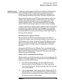
Check for usbscan.sys (Windows 98 SE Only)
The 82357A relies on a Microsoft driver called usbscan.sys that ships with
Windows 98/Me/2000/XP. However, for Windows 98 SE, this file and its
parent file, driver20.cab, may not be installed on your PC. Typically, the
usbscan.sys file is located under the system root directory at
\WINDOWS\SYSTEM32\DRIVERS\.
NOTE
usbscan.sys parent .cab file name is different for each Windows release.
The “driver20.cab” file name only applies to Windows 98 SE. The
usbscan.sys install problem is NOT expected on Windows Me/2000/XP
systems.
Windows 98 SE
Symptoms
If the usbscan.sys driver and the Microsoft .cab file (typically named
“driver20.cab” on Windows 98 systems) are not resident on your Windows
98 SE system, after you install the Agilent IO Libraries Suite and connect an
82357A to a USB port, a Windows Plug and Play Manager dialog box
appears that queries you for the location of usbscan.sys;driver20.cab.
If this dialog box appears:
If you have a Windows 98 SE CD: Insert the CD and browse to
x:\Win98. The install process will resume and the 82357A will begin
operation.
If you do not have a Windows 98 SE CD: Click Cancel on the dialog
box. Then, use one of the following methods to obtain the CD and
follow the step above.
- Locate the original Windows 98 SE Installation CD
- Contact your System Administrator for the CD
- Contact Microsoft for a replacement CD
54
Chapter 3
Troubleshooting the 82357A
Software Configuration Checks
Assigning usbscan If, when you initially plugged an 82357A into a USB port, a Windows Plug
Driver to the 82357A and Play Manager dialog box appeared that requested the location of
usbscan.sys and you were forced to click Cancel from this dialog box,
see the following information in this section. Otherwise, skip this section.
After an initial attachment of an 82357A to a system without usbscan.sys
installed, future unplugs/replugs of an 82357A will result in the system
(silently) assigning the wrong driver and not querying the user for the
usbscan.sys driver location. This action leaves the 82357A inoperative,
with all 3 LEDs ON (assuming the Agilent IO Libraries Suite is installed).
To properly associate the usbscan.sys driver with an 82357A, you can either
update the driver using the Windows Device Manager utility or uninstall/
reinstall the Agilent IO Libraries Suite (with the 82357A unattached) and
then attach the 82357A and provide the Windows 98 SE media location to
the Plug and Play Manager.
Uninstall/Reinstall the Agilent IO Libraries
With this method, the 82357A install software (found in the Agilent IO
Libraries Suite installer) cleans the Windows Registry of any memory of an
82357A being on the system, forcing the Plug and Play Manager to query
again for the location of usbscan.sys. This method has the side effect of
removing any Agilent IO Libraries Suite IO Configurations established
previously.
Disconnect all 82357As from the USB ports. Then, uninstall and reinstall
the Agilent IO Libraries Suite (version L.01.00 or greater, or 14.0 or greater).
Attach the 82357A and provide the Window 98 SE media location to the
Windows Plug and Play Manager.
Update the Driver using Windows Device Manager
With this method, you tell Windows that a new driver is to be assigned to the
82357A. This method requires you to locate where the Device Manager has
mistakenly located the 82357A device.
1
Start Windows Device Manager and select the 82357A device,
usually presented in Device Manager as an “Other” type device.
Then, select Properties for that device and then select the Driver tab
in the resulting dialog.
2
Click the Update driver... button and provide the Windows 98 SE CD
when prompted. This forces the Windows Plug and Play Manager to
reassess the drivers needed for that device, allowing you to provide
the usbscan.sys source media location.
Chapter 3
55
Troubleshooting the 82357A
Service/Support Information
Service/Support Information
This section provides service and support information for the 82357A and
lists numbers and a Web site you can use to contact Agilent about the
82357A.
82357A Service Information
There are no user-serviceable parts for the Agilent 82357A USB/GPIB
Interface Converter. If you suspect a hardware failure for the 82357A,
contact Agilent for instructions to return the unit. See the following section
“Contacting Agilent” for telephone numbers/web site address.
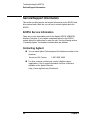
Contacting Agilent
You can reach Agilent Technologies at this telephone number for the
Americas:
Americas Call Center:
1-800-829-4444
For other countries, contact your country’s Agilent support
organization. A list of contact information for other countries is
available on the Agilent Web site:
http://www.agilent.com/find/assist
56
Chapter 3
4
82357A User’s Guide Information
82357A User’s Guide Information
This chapter provides general information for the 82357A User’s Guide,
including:
Guide Contents
Guide General Information
58
Chapter 4
82357A User’s Guide Information
Guide Contents
Guide Contents
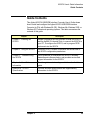
This Agilent 82357A USB/GPIB Interface Converter User’s Guide shows
how to install and configure the Agilent 82357A USB/GPIB Interface
Converter for PCs with Windows 98 (SE), Windows Me, Windows 2000, or
Windows XP Professional operating systems. This table summarizes the
contents of this guide.
Chapter
Description
Chapter 1 - Installing the
82357A
Shows a suggested six-step process to install the 82357A
and the Agilent IO Libraries Suite, to connect the 82357A to
your PC, to configure the 82357A, and to program GPIB
instruments via the 82357A
Chapter 2 - Using the 82357A
Describes 82357A modes of operation and shows how to
set 82357A configuration parameters.
Chapter 3 - Troubleshooting
the 82357A
Gives guidelines to troubleshoot the 82357A, including
hardware and software checks, and provides service and
support information for the 82357A.
Chapter 4 - User Guide
Information
Provides guide contents and general information for this
guide.
Appendix A - 82357A
Specifications
Provides technical specifications and supplementary
information for the 82357A.
Chapter 4
59
82357A User’s Guide Information
Guide General Information
Guide General Information
General Information for this guide follows, including:
Notice
U.S. Government Restricted Rights
Warranty Information
Trademark Information
Printing History
Copyright Information
Declaration of Conformity
Notice
The information contained in this document is subject to change without
notice.
Agilent Technologies shall not be liable for any errors contained in this
document. Agilent Technologies makes no warranties of any kind with
regard to this document, whether express or implied. Agilent Technologies
specifically disclaims the implied warranties of merchantability and fitness
for a particular purpose. Agilent Technologies shall not be liable for any
direct, indirect, special, incidental, or consequential damages, whether
based on contract, tort, or any other legal theory, in connection with the
furnishing of this document or the use of the information in this document.
U.S. Government Restricted Rights
The Software and Documentation have been developed entirely at private
expense. They are delivered and licensed as “commercial computer
software” as defined in DFARS 252.227- 7013 (Oct 1988), DFARS 252.2117015 (May 1991) or DFARS 252.227-7014 (Jun 1995), as a “commercial
item” as defined in FAR 2.101(a), or as “Restricted computer software” as
defined in FAR 52.227-19 (Jun 1987) (or any equivalent agency regulation
or contract clause), whichever is applicable. You have only those rights
provided for such Software and Documentation by the applicable FAR or
DFARS clause or the Agilent standard software agreement for the product
involved.
60
Chapter 4
82357A User’s Guide Information
Guide General Information
Warranty Information
A copy of the specific warranty terms applicable to your Agilent
Technologies product and replacement parts can be obtained from Agilent
Technologies, Inc.
Trademark Information
Windows ® 98, Windows ® Me, Windows NT 4.0, Windows ® 2000 and
Windows XP Professional are U.S. registered trademarks of Microsoft
Corporation. All other brand and product names are trademarks or
registered trademarks of their respective companies.
Printing History
Edition 1 - January 2002
Edition 2 - March 2003
Edition 3 - May 2004
Edition 4 - November 2004
Manual part number: 82357-90002
Copyright Information
Agilent Technologies 82357A USB/GPIB Interface Converter
User’s Guide
Copyright © 2002-2004 Agilent Technologies, Inc.
All rights reserved.
Declaration of Conformity
See the next page for the Declaration of Conformity for the 82357A
USB/GPIB Interface Converter.
Chapter 4
61
82357A User’s Guide Information
Guide General Information
DECLARATION OF CONFORMITY
According to ISO/IEC Guide 22 and CEN/CENELEC EN 45014
Manufacturer’s Name:
Manufacturer’s Address:
Agilent Technologies, Incorporated
815 – 14th St. SW
Loveland, CO 80537
USA
Declares under sole responsibility that the product as originally delivered
USB/GPIB Interface Converter
82357A
This declaration covers all options of the above product(s)
Product Name:
Model Number:
Product Options:
complies with the essential requirements of the following applicable European Directives, and
carries the CE marking accordingly:
EMC Directive (89/336/EEC, amended by 93/68/EEC)
Low Voltage Directive (73/23/EEC, amended by 93/68/EEC)
and conforms with the following product standards:
EMC
Standard
Limit
IEC 61326-1:1997+A1:1998 / EN 61326-1:1997+A1:1998
CISPR 11:1990 / EN 55011:1991
IEC 61000-4-2:1995+A1:1998 / EN 61000-4-2:1995
IEC 61000-4-3:1995 / EN 61000-4-3:1995
IEC 61000-4-4:1995 / EN 61000-4-4:1995
IEC 61000-4-6:1996 / EN 61000-4-6:1996
Group 1 Class A
4 kV CD, 8 kV AD
3 V/m, 80-1000 MHz
0.5 kV signal lines
3 V, 0.15-80 MHz 1 cycle, 100%
Canada: ICES-001:1998
Australia/New Zealand: AS/NZS 2064.1
The product was tested in a typical configuration with Agilent Technologies test systems.
IEC 61010-1:2001 / EN 61010-1:2001
Canada: CSA C22.2 No. 1010.1:1992
UL 61010B-1: 2003
Safety
Supplementary Information:
This DoC applies to above-listed products placed on the EU market after:
20 April 2004
Date
Ray Corson
Product Regulations Program Manager
For further information, please contact your local Agilent Technologies sales office, agent or distributor,
or Agilent Technologies Deutschland GmbH, Herrenberger Straße 130, D 71034 Böblingen, Germany.
62
Chapter 4
A
82357A Specifications
82357A Specifications
This appendix lists 82357A USB/GPIB Interface Converter Technical
Specifications and Supplementary Information.
64
Appendix A
82357A Specifications
Technical Specifications
Technical Specifications
General Requirements
Minimum System
Requirements
Windows 98 Second Edition /Me/2000/XP Professional, Pentium 200, 64 MB RAM, 55 MB free disk space, USB port (OS and Microsoft
.NET Framework may require more resources)
Supported Standards
USB 1.1*, IEEE-488.1 and IEEE-488.2 compatible, SICL and VISA 2.2
Supported Applications
(with IntuiLink)
Microsoft Excel 97 and 2000; Microsoft Word 97 and 2000. Check the
web for latest supported applications.
Supported Software
Development Applications
Visual Basic 6.0, Visual C++ 6.0, Visual Studio .NET, Agilent VEE 6.0
or greater, BASIC for Windows, LabVIEW 6.0 or greater
General Characteristics
Power
USB bus powered device, +5V, 500 mA (max), 200 mA (typ)
Connectors
Standard 24-pin IEEE-488, Standard USB A
USB Hubs
Self-powered hubs (Optional)
Dimensions
105 mm (L) x 64 mm (W) x 30 mm (H) (includes connectors)
Weight
215 grams
Cable
2.5 Meters, shielded, 1500 insertions
Indicators
READY, ACCESS, FAIL
Warranty
1 year
Environmental Specifications
Operating Environment
0oC to 55oC
Storage Environment
-40oC to +75oC
Humidity
up to 65% (0oC to 40oC)
Storage Humidity
up to 65% (0oC to 55oC)
Ordering Information
Interface
82357A USB/GPIB Interface Converter
Options
Opt 0B1 - Add Manual Set
Accessories
None
* USB 2.0 interfaces support the USB 1.1 standard.
Appendix A
65
82357A Specifications
Supplementary Information
Supplementary Information
This section provides supplementary information on the 82357A
performance, including supported GPIB modes.The 82357A is defined as a
controller as it can be (and is required to be) the system controller.
GPIB Modes of
Operation
Supported
The 82357A supports standard GPIB modes of operation, except for:
Parallel Poll (PPOLL)
Passing of Active Controller
Non-System Controller mode, which prevents using SICL
Commander sessions or VISA Servant sessions
IEEE-488.1 and
IEEE-488.2
Compliance
The 82357A is in full compliance with IEEE 488.1 and IEEE-488.2
specifications. The 82357A fully supports IEEE-488.1 subsets AH1,
C1, C2, C3, C4, C27, DC0, DT0, LE3, PP0, RL0, SH1, SR0, and TE7.
SRQ Response
Time
SRQ response time is slower than with the 82350 PCI GPIB interface as an
artifact of the USB implementation. In addition, sharing the USB bus with
other devices may impact GPIB performance.
Default T1 Delay
The default T1 delay for the 82357A is 800 nsec. See “Setting 82357A
High-Performance Operation” in Chapter 2 - Using the 82357A for details.
Maximum 82357A
System
Configuration
Up to four 82357As on a system have been successfully tested.
66
Appendix A
Index
I
A
Agilent IO Libraries Suite, verify
installation, 49
Agilent telephone number, 56
Agilent Web site, 56
C
changing configuration parameters, 39
changing modes of operation, 40
check IO Control operation, 52
check PC, 47
check USB cables, 47
check USB interface, 47
check USB scanner, 53
checking shipment, 8
compliance, IEEE, 66
configuration parameters, changing, 39
configuration parameters, setting, 39
connecting 82357A to PC, 14
connecting 82357A to USB hub, 15
Connection Expert, 21–25, 31, 36–40, 52
Administrator privileges required, 10
copyright information, 61
custom configuration, setting, 24
D
Declaration of Conformity, 61
default configuration, setting, 21
device manager, checking, 48
initial operating states, 35
installing the 82357A
before you install, 8
configuring the 82357A, 21
connecting GPIB instruments, 27
connecting the 82357A, 13
installing IO Libraries Suite, 10
programming via 82357A, 29
steps to install, 7
interface ID, 31
Interface Name, 31
IO Control operation, checking, 52
IO interface, 31
IO Libraries Suite, checking for installation,
10
iopen, 31
L
LED states, 35
Logical Unit Number, 31
M
maximum system configuration, 66
modes of operation, changing, 40
multiple 82357A operation, 38
multiple mode of operation, 36
P
PC
E
examples
IO Interface Configuration, 31
H
hardware checks, 47
hardware description, 13
high-performance operation, setting, 41
Index
power management, 49
suspend, 49
PC, checking, 47
PC, rebooting, 47
printing history, 61
programming GPIB instruments, 30
67
R
rebooting the PC, 47
restricted rights, 60
S
service and support, 56
service information, 56
setting configuration parameters, 39
setting custom configuration, 24
setting default configuration, 21
setting high-performance operation, 41
setting timeout floor values, 40
single 82357A operation, 37
single mode of operation, 36
software configuration checks, 52
software installation checks, 49
specifications, 65
SRQ operation, 38
SRQ performance, 66
supplementary information, 66
suspend/resume operation, 49
system requirements, checking, 9
usbscan driver, assigning to 82357A, 55
usbscan.sys, 9
usbscan.sys, checking, 54
using the 82357A, 34
V
viOpen, 31
VISA Assistant, 29
W
warranty, 60
Web site, Agilent, 56
Windows plug and play manager, 17
T
T1 delay, default, 66
telephone number, Agilent, 56
timeout floor values, setting, 40
trademark information, 61
troubleshooting
check device manager, 48
hardware checks, 47
software configuration checks, 52
software installation checks, 49
suspend/resume operation, 49
troubleshooting flowchart, 45
troubleshooting the 82357A, 44
U
USB cables, checking, 47
USB driver installation, verifying, 51
USB interface, checking, 47
USB scanner, checking, 53
68
Index
Agilent Technologies, Inc.
Printed in Malaysia
November 2004 E1104
*82357-90002*
User’s Guide
82357-90002