1
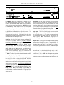
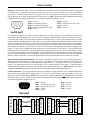
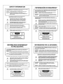
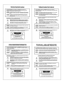
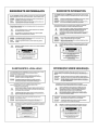
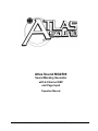
Atlas Sound MG2500
Sound Masking Generator
with 2-Channel DSP
and Page Input
Operation Manual
Atlas Sound, 1601 Jack McKay Blvd., Ennis, TX 75119 U.S.A. (800) 876-3333 http:// www.AtlasSound.com
blank
May 2002
MG2500
INTRODUCTION
TABLE OF CONTENTS
Front & Rear Panel Features
Setup
pg. 2
pgs. 3~11
Logic Inputs
pg. 12
RS-232 Control
pg. 13
Specifications & Block Diagram
pg. 14
Warranty
pg.15
Leveler FAQ’s
pg. 16
The Atlas Sound MG2500 Sound Masking Processor provides a digital pinknoise generator, a balanced line-level audio input, and a 2-channel DSP
processor, all in a single rack-space unit. Noise & audio levels, plus two
channels of EQ, gain management, & delay, are adjusted via computer
software. Sixteen presets can be recalled via contact-closures, RS-232, or
other remote control options. The MG2500 carries a five-year warranty.
MG2500 features include:
♦ pink-noise & audio input, with 2-channel DSP processor
♦ noise generator spectral purity (±0.1dB @ 0Hz~20kHz)
♦ precision pink-noise filtering (-3dB per octave low-pass)
♦ generator repeat time of noise (200 minutes)
♦ combined 1/3-octave & parametric equalization per channel
♦ selectable high & low frequency shelving filters per channel
♦ HPF & LPF with variable frequency & slope per channel
♦ leveling, compression, limiting, & soft-gating per channel
♦ output delay, with distance/delay calculation, per channel
♦ two independent matrixes for channel-to-channel mixing
♦ variable noise, input, & output levels with software metering
♦ sixteen non-volatile memory presets store/recall settings
♦ balanced input & outputs on plug-in barrier strip connectors
♦ software for Windows 95/98/NT/2000/XP & cable included
®
♦ no manual controls on front panel, to prevent tampering
♦ remote control via RS-232 & programmable logic inputs
♦ incorporates AES recommended grounding practices
♦
marked and UL / C-UL listed power source
♦ covered by Atlas Sound’s five-year warranty
1
FRONT & REAR PANEL FEATURES
MG2500
Sound Masking Processor
~
27V
50/60 Hz
serial port
12 watts
class 2 wiring
MG2500
on
Atlas Sound LP
1601 Jack
McKay Blvd
Ennis, TX 75119
Sound Masking Processor
link port
link
logic inputs
output 2
output 1
Made in U.S.A.
input
On Indicator: When power is applied to the MG2500, this red
LED will light indicating power to the unit is On. When power is
turned off, all current settings will be stored in non-volatile memory
and recalled when power is turned back on. NOTE: During setup
the MG2500 may instead be set to recall a special preset
whenever power is turned on (see Setup on pg. 10).
Link Switch: The Link Switch is used when connecting multiple
devices in a ‘Link Port to Serial Port’ configuration (see Link Port
above). From the factory, the Link Switch is released (out). When
connecting multiple devices, the Link Switch must be depressed
(in) on all devices except the final device in the system (the device
with no Link Port connection). NOTE: The Link switch must
remain OUT when only a single device is being used.
AC Power Cord: The power transformer provides 27 Volts AC to
the MG2500, and is detachable via a 5-pin DIN connector. The
MG2500 has two internal ‘self-resetting’ fuses (there are no user
serviceable parts inside the unit). If the internal fuses blow, they
will attempt to re-set after a short period. However, this may be an
indication that the MG2500 requires service.
Logic Inputs: This 25-pin Sub-D (female) connector provides
sixteen logic inputs for controlling the MG2500 via contact-closures
(see Logic Inputs on pg. 12). Logic Inputs are programmed using
the software and serial cable provided with the MG2500 (see
Setup on pg. 10). NOTE: From the factory, Logic Inputs 1~16
have no pre-programmed function.
Serial Port: This 9-pin Sub-D (male) connector provides an RS232 Serial Port for remote control via computer or third-party
controllers (see RS-232 Control on pg. 13). The Serial Port has
the following pin assignments (left-to-right & top-to-bottom): Pin 1)
not used; Pin 2) Receive Data (RxD) input; Pin 3) Transmit
Data (TxD) output; Pin 4) Data Terminal Ready (DTR) output;
Pin 5) Ground; Pin 6) not used; Pin 7) Request To Send (RTS)
output; Pin 8) not used; Pin 9) not used. The default baud rate
for the Serial Port is 38,400 (See RS-232 Control on pg. 13). Atlas
Sound MG2500 software and a serial cable are provided for
®
programming via Windows 95/98/NT/2000/XP (see Setup on pg.
3). NOTE: The Serial Port can also transmit commands received
via the Logic Inputs (see Setup on pg. 10).
Outputs 1 & 2: These plug-in barrier strips provide the balanced
analog line-level Outputs from processor Channels 1 & 2. For
balanced output, wire high to (+), low to (-), and ground to ( ). For
unbalanced output, wire high to (+) and ground to ( ), leaving (-)
unconnected. Signal level will be reduced by 6dB when outputs
are unbalanced.
Input: This plug-in barrier strip provides the balanced analog linelevel audio input. For balanced input, wire high to (+), low to (-),
and ground to ( ). For unbalanced input, wire high to (+) and
ground to both (-) & ( ). NOTE: The internal pink-noise generator
provides a second input. Input & noise may be assigned in any
combination to the two processing channels (see Setup on pg. 4).
Link Port: This 9-pin Sub-D (female) connector provides a Link
®
Port for RS-232 control of multiple ATLAS SOUND MG2500’s
(see RS-232 Control on pg. 13). The Link Port of one device
simply connects to the Serial Port of the next device (and so forth).
NOTE: All but the final MG2500 in a system should have the Link
Switch pressed in (see below). The Link Port has the following pin
assignments (right-to-left & top-to-bottom): Pin 1) not used; Pin
2) Transmit Data (TxD) output; Pin 3) Receive Data (RxD) input;
Pin 4) not used; Pin 5) Ground; Pin 6) not used; Pin 7) not
used; Pin 8) not used; Pin 9) not used. NOTE: The Link Port
will also transmit commands received via the Logic Inputs (see
Setup on pg. 10).
2
SETUP
®
MG2500 parameters are all adjustable using the Windows 95/98/NT/2000/XP software and serial cable provided with the unit. The
MG2500 program includes several control screens, which are described on the following pages. Once the software is started (and Comm
Port Configuration is set), the control screens are accessed via the drop-down menus at the top of the opening screen. The Main screen
appears whenever an MG2500 file is opened. Gain Matrix #1, Gain Manager, EQ, Gain Matrix #2, & Delay screens are then available from
the Main screen. Logic Definition & Configuration Options screens are also available from the Configure MG2500 menu. The File menu
provides functions such as save, open, download, etc. The Settings menu recalls the Comm Port Configuration screen. The Window
menu arranges the active product screens. The Help menu explains the available adjustments. To install MG2500 Software: Select ‘Run’
®
from the ‘Start’ menu, and enter A:\SETUP. System Requirements: Windows 95/98/NT/2000/XP with 5MB of available hard disk space
(serial port required for ‘on-line’ operation).
MAIN SCREEN
The Main Screen is used to adjust MG2500 input/output levels, to access the processing control screens, and to store/recall Presets 1~16.
Adjustments are made with the computer mouse (or keyboard). Input, Noise, Output 1, & Output 2 levels are adjusted by dragging the
corresponding ‘faders’ up or down. These are the analog signal input & output circuits. ‘Meters’ are provided on each channel to display
input/output levels at specific points along the digital signal processing paths, and at the analog outputs. NOTE: For best performance,
adjust levels so the meters show occasional peaks in the yellow area, but never to the top (red). Output 1 Mute & Output 2 Mute will toggle
the respective output signal on/off, as well as indicate the output muting status. Logic Inputs indicators will light whenever the respective
Logic Inputs are turned on via external remote control (see Logic Inputs on pg. 12). Preset buttons recall the corresponding presets from
non-volatile memory. Presets must first be created & stored by the user (no factory presets). The Store button opens a menu for storing
current settings in any of the Presets 1~16. Presets may be stored and recalled (in total or in part) via remote control (see Logic Input
Definitions screen on pg. 10). The title bar across the top of the Main screen will indicate the Device #, the custom Device Name, and the
model of product being controlled. MG2500 software can operate ‘off-line’ (with no product connected) by opening a ‘new’ file for the
desired product. The Device # for ‘off-line’ files is assigned sequentially as a negative number.
3
SETUP
GAIN MATRIX #1 SCREEN
The Gain Matrix #1 screen provides a channel-to-channel (2x2) mix matrix, which can be used to adjust the amount of Input & Noise signal
being routed to each of the processing channels (Output 1 & Output 2). From the factory, Input 1 is routed to Output 1 only, and Noise is
routed to Output 2 only, providing two independent signal paths. Levels are adjusted by dragging the corresponding ‘faders’ up or down.
‘Meters’ are provided on each channel to display input/output levels at Gain Matrix #1. NOTE: For best performance, adjust levels so the
meters show occasional peaks in the yellow area, but never to the top (red). Invert allows the phase of each corresponding signal path to
be reversed (180°).
The MG2500 has two basic applications which utilize Gain Matrix #1:
1) Input 1 can be routed to Output 1 and Noise can be routed to Output 2. Each channel of processing is dedicated to either Input 1 or
Noise signal. Switching between Input 1 & Noise signals (to either Output) is then accomplished via Gain Matrix #2 presets (see Gain
Matrix #2 screen on pg. 8). This is effective when only a single output (zone), or two outputs (zones) with independent delay, are required.
2) Gain Matrix #1 presets can be used to switch between Input 1 or Noise signal being routed to either Output. Each channel of
processing is dedicated to a specific Output (zone), via Gain Matrix #2. Separate EQ presets for Input 1 & Noise signals, as they appear at
each output (zone), can also be used. This is effective when two outputs (zones), each with dedicated processing, are required.
Of course, the MG2500 can simply be configured for processing Noise (or Input 1) signal only, at both Outputs.
4
SETUP
GAIN MANAGER SCREEN
The Gain Manager screen is used to adjust Leveler, Compressor, Limiter & Soft Gate settings for each of the processing channels (Output
1 & Output 2). Threshold adjusts the signal level at which the Leveler, Compressor, & Limiter functions are triggered. Therefore, these
controls determine the amount and type of gain processing to be applied to the signals. The Leveler controls the long-term average signal
level. If the average signal level increases, the Leveler will reduce gain to compensate. If the average signal level decreases, the Leveler
will increase gain to compensate. The Compressor controls short-term peaks in signal level by providing ‘soft-knee’ compression, which
automatically varies in ratio from 1.1:1 on signals just slightly above Threshold, to more than 10:1 at full compression. The Compressor
responds to average & peak levels, working with the Leveler to maintain a constant output level. The Limiter controls short-term peaks in
signal level by providing ‘hard’ limiting, which establishes an absolute ceiling level. The Limiter provides protection against clipping
distortion, and the chance of amplifier overload or speaker damage, due to sudden transients. From the factory, the default Threshold
settings will provide approximately 6dB of gain reduction on input signals of nominal level. Bypass defeats the individual Leveler,
Compressor, or Limiter functions for that Channel, without changing the actual settings. Soft Gate Bypass defeats a downward expander
circuit for that Channel, which reduces gain 2dB for each 1dB that signal falls below threshold (-30dBu). The Soft Gate gracefully
attenuates background/ambient noise during periods of silence. Bypass GM defeats all Leveler, Compressor, Limiter, & Soft Gate
functions for that Channel, without changing the actual settings. ‘Meters’ are provided on each channel to display input/output levels, as
well as the amount of gain reduction, at the Gain Manager section. NOTE: The Gain Manager provides gain reduction even on input
signals of nominal level. Therefore, all subsequent meters will indicate the resultant lower levels. CAUTION: The Gain Manager can
increase gain for lower level signals. Therefore, after all system settings have been adjusted, temporarily bypass the Gain Manager as a
test of system feedback stability. If acoustic feedback occurs, reduce the system amplifier levels or use the MG2500 parametric equalizer
to eliminate feedback nodes, before re-enabling the Gain Manager.
5
SETUP
PARAMETRIC EQ SCREEN
The Parametric EQ screen is used to adjust equalization for each of the processing channels (Output 1 & Output 2). Up to 28 bands of
equalization, plus high-pass & low-pass filters, are available per channel. NOTE: Parametric & Graphic equalization techniques may be
used simultaneously on the same channel, as long as the total number of bands per channel does not exceed 28. Frequency selects a
center frequency for the current band. Gain selects the amount of cut or boost applied at the center frequency for the current band.
Bandwidth selects the range of frequencies, above & below the center frequency, which will also be affected by the current band.
Frequency, Gain, & Bandwidth may also be adjusted by dragging the cursors shown inside the upper graph area. Dragging the solid dot
affects both Frequency & Gain. Dragging either of the open circles will affect Bandwidth. Add advances to a new parametric filter band (at
1kHz), leaving place-mark cursors for any previous bands. NOTE: Initially, there are no parametric filter bands available for adjustment,
until Add has been selected. Delete erases the current band, and returns to the previous band. Delete All erases all parametric bands.
Bands Used & Bands Available are shown above. The lower graph area shows the cumulative effect of all equalization. Right-clicking
provides a menu of copy/paste functions, which allows settings of the 28 bands, plus high-pass & low-pass filters, to be copied from one
channel to the other, or to another unit. ‘Meters’ are provided on each channel to display input/output levels at the EQ section. EQ Mode
selects the Parametric EQ Screen or the Graphic EQ Screen (see Graphic EQ Screen on next page). Low Shelf adds a low-frequency
shelving parametric band. High Shelf adds a high-frequency shelving parametric band. NOTE: Low Shelf & High Shelf bands are NOT
affected by the Delete or Delete All buttons. They may only be deleted by means of their individual check boxes. Bypass EQ defeats all
parametric & graphic equalization for that channel, without changing actual settings
6
SETUP
GRAPHIC EQ SCREEN
The Graphic EQ screen is used to adjust equalization for each of the processing channels (Output 1 & Output 2). Up to 28 bands of
equalization, plus high-pass & low-pass filters, are available per channel. NOTE: Parametric & Graphic equalization techniques may be
used simultaneously on the same channel, as long as the total number of bands per channel does not exceed 28. Default operation of the
Graphic EQ is 1/3-octave, 28-bands, and ISO standard center frequencies. Therefore, gain for each band can be simply adjusted by
dragging the square cursors up or down inside the upper graph area. Flat erases all graphic bands, setting all faders to the center line.
Right-clicking provides a menu of copy/paste functions, which allows settings of the 28 bands, plus high-pass & low-pass filters, to be
copied from one channel to the other, or to another unit. Bands Used & Bands Available are shown above. The lower graph area shows
the cumulative effect of all equalization. ‘Meters’ are provided on each channel to display input/output levels at the EQ section. EQ Mode
selects either Parametric or Graphic equalization (see Parametric EQ Screen on previous page). HPF Slope enables a High-Pass Filter by
selecting a desired slope. LPF Slope enables a Low-Pass Filter by selecting a desired slope. Once a High-Pass Filter or Low-Pass Filter
is enabled, a square cursor appears in the upper graph area to allow frequency adjustment for that filter. The effect of High-Pass & LowPass Filters is also shown in the lower graph area. NOTE: HPF & LPF are NOT affected by the Flat button. They may only be deleted by
means of their individual menu boxes. Bypass EQ defeats all parametric & graphic equalization filters for that channel, without changing
actual settings.
7
SETUP
GAIN MATRIX #2 SCREEN
The Gain Matrix #2 screen provides a channel-to-channel (2x2) mix matrix (identical to Gain Matrix #1), which can be used to adjust the
amount of signal being routed from each channel to the other. From the factory, Channel 1 is routed to Output 1 only, and Channel 2 is
routed to Channel 2 only, providing two independent signal paths. Levels are adjusted by dragging the corresponding ‘faders’ up or down.
‘Meters’ are provided on each channel to display input/output levels at Gain Matrix #1. NOTE: For best performance, adjust levels so the
meters show occasional peaks in the yellow area, but never to the top (red). Invert allows the phase of each corresponding signal path to
be reversed (180°).
The MG2500 has two basic applications which utilize Gain Matrix #2:
1) Each channel of processing is dedicated to either Input 1 or Noise signal, using Gain Matrix #1 (see Gain Matrix #1 screen on pg. 4).
Switching between Input 1 & Noise signals (to either Output) is then accomplished via Gain Matrix #2 presets. This is effective when only a
single output (zone), or two outputs (zones) with independent delay, are required.
2) Gain Matrix #1 presets can be used to switch between Input 1 or Noise signal being routed to either Output (see Gain Matrix #1 screen
on pg. 4). Each channel of processing is dedicated to a specific Output (zone), via Gain Matrix #2. Separate EQ presets for Input 1 &
Noise signals, as they appear at each output (zone), can also be used. This is effective when two outputs (zones), each with dedicated
processing, are required.
Of course, the MG2500 can simply be configured for processing Noise (or Input 1) signal only, at both Outputs.
8
SETUP
DIGITAL DELAY SCREEN
The Digital Delay screen is used to adjust delay time settings for each Output. Delay time is shown in the window, with adjacent buttons
providing the up/down adjustments. Coarse buttons change the delay time in 1 milli-second increments. Fine buttons change the delay
time in 21 micro-second increments. Delay time may also be entered directly into the window, but will be rounded to the nearest available
setting. Msec allows delay times to instead be entered & calculated in terms of distance measurements (inches, feet, centimeters, or
meters). Bypass temporarily sets delay time for the correspnding Output to minimum (1.333 msec).
9
SETUP
LOGIC INPUT DEFINITIONS SCREEN
The Logic Input Definitions screen is used to assign specific ‘actions’ to the sixteen Logic Inputs. Logic Inputs allow remote control of the
MG2500 via external circuits, such as switches, contact-closures, active driver circuits, and/or ‘open-collector’ logic outputs (see Logic
Inputs on pg. 12). From the factory, Logic Inputs 1~16 have no pre-programmed functions. However, using the Logic Input Definitions
screen, each Logic Input may be assigned various ‘actions’. Logic Inputs selects which Logic Input is to be defined. NOTE: Since Logic
Inputs are controlled by switches, contact-closures, etc., each Logic Input may be assigned certain actions to perform when the switch is
‘opened’, and different actions to perform when that same switch is ‘closed’. Binary Mode selects a special group of Logic Inputs which
can also be defined. This allows certain actions to be performed only when a specified condition of open/closed Logic Inputs exists within
the group. When a Binary Mode is selected, indicators for the chosen group of Logic Inputs will appear below. Binary Combination then
selects the specific combination of open/closed (on/off) Logic Inputs that needs to exist (for the assigned actions to be performed). When a
combination is selected, indicators will light (red) to designate which of the Logic Inputs within the group are closed (on) for that condition.
NOTE: When a Binary Mode is selected, the chosen group of Logic Inputs can no longer be defined individually. It is not necessary to
select a Binary Mode when simply defining individual Logic Inputs. Power-Up Actions allows specific actions to be assigned for the
MG2500 to perform each time power is turned on. Echo Character selects the RS-232 ASCII character which will be transmitted via the
MG2500 Serial Port whenever the selected Logic Input is switched. NOTE: From the factory, no echo characters are assigned to the
Logic Inputs. Echo Characters are used primarily for customizing remote control commands amongst various RS-232 controlled products
within a system (see RS-232 Control on pg. 13). Store System Preset allows store actions for Temp Presets A~D to be assigned to the
selected Logic Input. Temp Presets A~D allow current settings of the MG2500 to be temporarily stored in memory. Temp Presets are
useful when re-establishing settings which existed prior to a change. For example: recalling settings for noise masking, after paging has
occurred. Recall System Preset allows recall actions for Presets 1~16, and Temp Presets A~D, to be assigned to the selected Logic Input.
NOTE: System Preset actions affect settings from all stages of the MG2500 (Inputs, Gain Matrix #1, Gain Manager, EQ, Gain Matrix #2,
Delay, & Outputs). However, the settings that Presets 1~16, and Temp Presets A~D, store for specific stages of the MG2500 may be
recalled independently. Input/Noise Gain, Gain Matrix #1, Output 1/2 Gain Manager, Output 1/2 EQ, Gain Matrix #2, Output 1/2 Delay, and
Output 1/2 Gain allow recall actions for their respective portions of Presets 1~16, and Temp Presets A~D, to be assigned to the selected
Logic Input. For example: two independent processing channels, each with independent preset selection. Output 1/2 Gain also allow
various output volume & muting actions to be assigned to the selected Logic Input. Clear allows all actions assigned to the selected Logic
Input (or all Logic Inputs) to be cleared. Help provides additional instruction. Close will close the Logic Input Definition screen.
10
SETUP
CONFIGURATION OPTIONS SCREEN
The Configuration Options screen is used to select options which customize the operation of the MG2500. At the top of the Configuration
Options screen, the Serial Number and Firmware Version of the MG2500 will be displayed. MG2500 software can operate ‘off-line’ (with
no product connected) by opening a ‘new’ file. The Serial Number and Firmware Version are not displayed for ‘new’ (‘off-line’) files.
Device Name allows a custom name to be given to the particular MG2500, by entering up to 30 characters of text. The Device Name will
be stored in the MG2500 memory, and will be displayed on the title bar of the Main screen whenever that MG2500 is accessed with the
software. Device Number allows a device number (0~63) to be assigned to the currently active MG2500. This allows multiple MG2500 (or
®
other ATLAS SOUND programmable products) to be individually controlled when linked together. Unique device numbers must be
assigned to each device before the devices are linked together. Temperature selects the desired air temperature to be used in calculating
Velocity of Sound (seen below). Temperature, and the resultant Velocity of Sound, are global parameters which affect distance/delay
calculations for the Delay section. Set Password allows the MG2500 to be assigned a password (up to seven characters), which will then
be required before any future software communication with that unit is allowed. NOTE: When multiple programmable products are
connected in a system configuration (via Serial & Link Ports), it is strongly recommended that only one unit in the system be assigned a
password. A single unit having a password will prevent software communication with all units in the system. Communication with other
units will still be possible, but only by first dis-connecting them from the unit which has been assigned a password. Help provides
additional instruction. Close will close the Configuration Options screen.
11
LOGIC INPUTS
Sixteen Logic Inputs are available on a rear panel 25-pin Sub-D (female) connector. Logic Inputs allow remote control of the MG2500 via
external circuits, such as switches, contact-closures, active driver circuits, and/or ‘open-collector’ logic outputs. From the factory, Logic
Inputs 1~16 have no pre-programmed function. However, each Logic Input may be assigned different ‘actions’ using the MG2500 software
and serial cable provided with the unit (see Setup on pg. 10). Since Logic Inputs are controlled by switches, contact-closures, etc., each
Logic Input may be assigned two functions (one for switch ‘closed’ and one for switch ‘open’).
Logic Inputs have the following pin assignments (right-to-left & top-to-bottom): Pins 1~16) Logic Inputs 1~16; Pins 17~25) Ground.
13
1
25
14
logic inputs
logic inputs
pin numbers
logic #1~16
pin #1~16
ground
pin #17~25
When nothing is connected to a Logic Input, an internal pull-up resistor keeps it at a ‘high’ idle state (+5.0 VDC). The Logic Input is
activated when its input goes ‘low’ (less than +0.8 VDC), and is de-activated when its input goes ‘high’ (greater than +2.4 VDC). A Logic
Input is controlled in one of three ways: 1) Use an NPN style ‘open-collector’ logic output from an external device (such as another
product or third-party controller) to short the Logic Input to ground. 2) Use a switch, relay, or other contact-closure (such as from a thirdparty controller) to short the Logic Input to ground. 3) Use an active TTL output driver circuit (such as from a third-party controller) to
actively drive the Logic Input to a ‘high’ or ‘low’ state.
Multiple contact-closures or ‘open-collector’ logic outputs may be wired in parallel to a single Logic Input (see diagram below). Logic
Outputs and contact-closures should be rated for at least 5 Volts / 1mA operation. Low-current / dry-contact closures are recommended
for reliability. Active output driver circuits should not exceed a signal range of 0~5 Volts DC, and should have a minimum pulse width of
100 milli-seconds. Logic Input impedances are approximately 10k ohms.
multiple switches to single Logic Input
13
25
1
14
12
RS-232 CONTROL
Serial Port: The 9-pin Sub-D (male) connector on the MG2500 rear panel provides the RS-232 compatible serial interface signals used
for computer control. The MG2500 Serial Port transmits serial data on pin 3 (TxD), receives serial data on pin 2 (RxD), and provides a
ground on Pin 5. The Data Terminal Ready (DTR) & Request To Send (RTS) output signals are connected to the +12 Volt power supply
(through a resistor) and are always asserted when the MG2500 power is on. NOTE: The Serial Port may also transmit commands which
are received via the Logic Inputs, depending upon the echo character assignments (see Setup on pg. 10).
1
2
6
3
7
4
8
pin #1
pin #2
pin #3
pin #4
pin #5
5
9
=
=
=
=
=
not used
Receive Data (RxD) input
Transmit Data (TxD) output
Data Terminal Ready (DTR) output
ground
pin #6
pin #7
pin #8
pin #9
=
=
=
=
not used
Request To Send (RTS) output
not used
not used
serial port
The MG2500 only requires receive data (pin 2), transmit data (pin 3), and signal ground (pin 5) to be connected for successful data
communications (see cable diagram below). However, the PC may require that signals be present on the data set ready, clear to send, or
carrier detect inputs, as well as the receive data, transmit data, and signal ground pins. Success or failure depends entirely on the actual
computer hardware and software being used. When trying to solve an interfacing problem, the most important thing to remember is that an
output of one device should connect to one or more inputs of the other device, and that two outputs should never be connected together.
Also, keep in mind that the RS-232 specification calls for the cable length to be no greater than 50 feet (although it is not unusual to be
able to operate over distances of 150 to 250 feet), and the connectors must be of the appropriate gender (male or female) to mate
properly. For best results, a shielded cable should be used, with the shield connected to chassis ground. Since the MG2500 serial
interface ground is also tied (indirectly) to the analog signal ground, undesirable ground loops may occur when the MG2500 is connected
to a PC (if the system grounding is not carefully designed). For best performance, the PC ground and the chassis ground of the MG2500
should be at the same potential, and the PC should get AC power from the same source as the MG2500 (and any other audio equipment
which is connected to the MG2500). Since most lap-top computers are isolated from earth ground, this should rarely pose a problem.
Serial Port Data Communications Parameters: The MG2500 communicates through the Serial Port at the factory selected rate of
38400 bits per second, with 8 data bits, 1 stop bit, and no parity. The MG2500 utilizes a subset of the standard 7-bit ASCII character set.
The eighth data bit of each character (the most significant bit) should always be 0. The computer should not echo the characters it
receives. The computer should not be set for either hardware (DTR) or software (XON/XOFF) flow control. The baud rate may be
changed to either 2400, 9600, or 19200 bits per second by means of the software (see Setup on pg. 3). NOTE: Baud rate may need to be
changed when the MG2500 is being used in RS-232 systems with other products having a lower maximum baud rate.
Link Port Connections: The 9-pin Sub-D (female) connector on the MG2500 rear panel provides the RS-232 compatible serial interface
signals used for linking multiple products within a system. The Link Port of one device simply connects to the Serial Port of the next
device, and so forth (see diagram below). NOTE: All but the final device in a system should have its ‘Link’ switch pressed in (see Front &
Rear Panel Features on pg. 2). The Link Port may also transmit commands which are received via the Logic Inputs, depending upon the
echo character assignments (see Setup on pg. 10).
5
4
9
3
8
2
7
pin #1
pin #2
pin #3
pin #4
pin #5
1
6
=
=
=
=
=
not used
Transmit Data (TxD) output
Receive Data (RxD) input
not used
ground
pin #6
pin #7
pin #8
pin #9
=
=
=
=
not used
not used
not used
not used
link port
PC
CD
RxD
TxD
DTR
gnd
DSR
RTS
CTS
RI
serial port
1
2
3
4
5
6
7
8
9
male
1
2
3
4
5
6
7
8
9
female
Serial Cable
(shield)
serial port
1
2
3
4
5
6
7
8
9
female
1
2
3
4
5
6
7
8
9
male
MG2500
MG2500
n/a
TxD
RxD
n/a
gnd
n/a
n/a
n/a
n/a
n/a
RxD
TxD
DTR
gnd
n/a
RTS
n/a
n/a
13
link port
1
2
3
4
5
6
7
8
9
female
1
2
3
4
5
6
7
8
9
male
Link Cable
(shield)
serial port
1
2
3
4
5
6
7
8
9
female
1
2
3
4
5
6
7
8
9
male
unit 2
n/a
RxD
TxD
DTR
gnd
n/a
RTS
n/a
n/a
SPECIFICATIONS & BLOCK DIAGRAM
Frequency Response (20Hz~20kHz @ +4dBu):
+0/-0.5dB
Sampling Rate:
THD+Noise (20Hz~20kHz @ +4dBu):
< 0.002%
A/D & D/A Converters:
> 100dB
Power Consumption:
Dynamic Range (20Hz~20kHz):
Maximum Gain:
20dB
Input Impedance (balanced):
Output Impedance (balanced):
Maximum Output (balanced):
< 15 watts
height (1 rack space)
1.75” (44mm)
+24dBu
width
19” (483mm)
200 ohms
depth
7” (178mm)
+24dBu
Weight:
4.5 lbs. (2.04kg)
MG2500 Block Diagram
Input 1
gain
gain
Output 1
D/A
A/D
matrix
internal
pink-noise
generator
128x oversampled 24-bit sigma delta
Dimensions:
20k ohms
Maximum Input (balanced):
48kHz
gain
matrix
gain
manager
equalizer
delay
gain
manager
equalizer
delay
Output 2
A/D
D/A
gain
Digital Signal Processing Blocks
receive
send
RS-232
serial
port
logic inputs
link port
14
WARRANTY
ATLAS SOUND IS PLEASED TO EXTEND THE FOLLOWING 5-YEAR LIMITED
WARRANTY TO THE ORIGINAL PURCHASER OF THE PROFESSIONAL
SOUND EQUIPMENT DESCRIBED IN THIS MANUAL.
Limited Warranty:
All products manufactured by Atlas Sound are
warranted to the original dealer/installer,
industrial or commercial purchaser to be free
from defects in material and workmanship and to
be in compliance with our published
specifications, if any. “This warranty shall extend
from the date of purchase for a period of five
years on the Atlas Sound MG2500.
Electrolytic capacitors, and the normal wear
and tear of appearance items such as paint,
knobs, handles, fuses and lamps are not
covered under this warranty.
EXCEPT TO THE EXTENT THAT APPLICABLE
LAW PREVENTS THE LIMITATION OF
CONSEQUENTIAL DAMAGES FOR
PERSONAL INJURY, ATLAS SOUND SHALL
NOT BE LIABLE IN TORT OR CONTRACT
FOR ANY DIRECT, CONSEQUENTIAL OR
INCIDENTAL LOSS OR DAMAGE ARISING
OUT OF THE INSTALLATION, USE OR INABILITY TO USE THE PRODUCTS. THE
ABOVE WARRANTY IS IN LIEU OF ALL
OTHER WARRANTIES INCLUDING BUT NOT
LIMITED TO WARRANTIES OF MERCHANTABILITY AND FITNESS FOR A
PARTICULAR PURPOSE.
Returns:
No merchandise will be accepted for return
without prior authorization. Unauthorized returns will be refused and placed in the hands
of the carrier at the expense of the shipper.
To request a return authorization number
please call the Atlas Sound warranty
department at 800-876-3333.
This warranty will be VOIDED if the serial
number has been removed or defaced; or if
the product has been subjected to accidental
damage, abuse, rental usage, alterations, or
attempted repair by any person not
authorized by ATLAS SOUND to make
repairs; or if the product has been installed
contrary
to
ATLAS
SOUND
recommendations.
Atlas Sound will solely at its discretion, re-place
at no charge or repair free of charge defective
parts or products when the product has been
applied and used in accordance with our
published operation and installation instructions.
We will not be responsible for defects caused by
improper storage, misuse (including failure to
provide reasonable and necessary
maintenance), accident, abnormal atmospheres,
water immersion, lightning discharge, or
malfunctions when products have been modified
or operated in excess of rated power, altered,
serviced or installed in other than a workmanlike
manner. The original sales invoice should be
retained as evidence of purchase under the
terms of this warranty. All warranty returns must
comply with our re-turns policy set forth below.
When products returned to Atlas Sound do not
qualify for repair or replacement under our
warranty, repairs may be performed at prevailing
costs for material and labor unless there is
included with the returned product(s) a written
request for an estimate of repair costs before
any non-warranty work is performed. In the event
of replacement or upon completion of repairs,
return shipment will be made with the
transportation charges collect.
15
Q: What is this ’Leveler’ inside the MG2500?
The Leveler function, in the Gain Manager section of an MG2500, is an automatic gain control (AGC). This means that the
Leveler automatically adjusts volume levels up or down to compensate for signals that are softer or louder than normal.
Q: What can this ’Leveler’ do for me and my customer?
The two most common applications for the Leveler are to control music sources which have been recorded at different levels,
and to control different levels of speech caused by the person(s) speaking and/or their varying distances from the microphones.
Example: A background music system utilizing a CD player as the primary source. Since CDs can be recorded at different
levels, the volume from one CD to another can vary significantly. In the background music system it is desirable for the music
to maintain a consistent level. A Limiter or Compressor could be employed, but they would only squash the dynamics, and
diminish the quality of the music signal. A Leveler, on the other hand, actually controls the overall level of the signal, without
adversely affecting the dynamics of the signal itself. Therefore, a Leveler can be used to provide a constant volume from the
system, regardless of varying CD levels. This is also true for systems with a variety of music sources (i.e...cassette, tuner,
etc.).
Q: How should I adjust this ’Leveler’ to do what I want?
1) Using a typical input signal, adjust the source output and the MG2500 input for proper levels.
(The MG2500 software input meter should indicate occasional peaks into the yellow, but never to the red.)
2) Select the Gain Manager section of the MG2500 software.
3) Bypass all Gain Manager functions except the Leveler.
(This allows the Gain Reduction meter to be used for setup of the Leveler specifically.)
4) Adjust the Leveler ’threshold’ so the Gain Reduction meter indicates the desired amount of gain reduction.
(The amount of gain reduction employed on ’normal’ level signals equals the gain available for raising ’softer’ level signals.)
(Example: Play a normal level CD. Adjust for 6dB of gain reduction. CDs with lower levels can be raised as much as 6dB.)
(Likewise, ’louder’ signals will be lowered. The Leveler will attempt to bring softer or louder signals to the threshold level.)
NOTE: The Gain Manager provides gain reduction even on input signals of nominal level. Therefore, all subsequent software
meters will indicate the resultant lower level. This lower level can then be compensated for by increasing the input level on the
next device in the system (i.e...power amplifier).
CAUTION: The Gain Manager can increase gain for lower level signals. Therefore, once all of the system settings have been
adjusted, temporarily bypass the Gain Manager as a test of system feedback stability. If acoustic feedback occurs, reduce the
system amplifier level or use the MG2500 parametric equalizer to eliminate feedback nodes, before re-enabling the Gain
Manager.
16