1
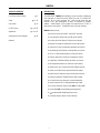
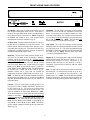
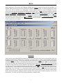
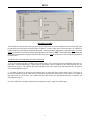
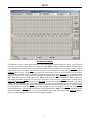
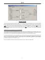
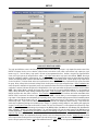
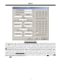
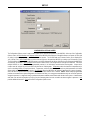
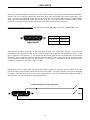
NMP200 Noise Masking Processor Operation Manual ® Biamp Systems, 10074 S.W. Arctic Drive, Beaverton, Oregon 97005 U.S.A. (503) 641-7287 http://www.biamp.com blank print update Aug 8/01 Q: What is this ’Leveler’ inside the NMP200? The Leveler function, in the Gain Manager section of an NMP200, is an automatic gain control (AGC). This means that the Leveler automatically adjusts volume levels up or down to compensate for signals that are softer or louder than normal. Q: What can this ’Leveler’ do for me and my customer? The two most common applications for the Leveler are to control music sources which have been recorded at different levels, and to control different levels of speech caused by the person(s) speaking and/or their varying distances from the microphones. Example #1: A background music system utilizing a CD player as the primary source. Since CDs can be recorded at different levels, the volume from one CD to another can vary significantly. In the background music system it is desirable for the music to maintain a consistent level. A Limiter or Compressor could be employed, but they would only squash the dynamics, and diminish the quality of the music signal. A Leveler, on the other hand, actually controls the overall level of the signal, without adversely affecting the dynamics of the signal itself. Therefore, a Leveler can be used to provide a constant volume from the system, regardless of varying CD levels. This is also true for systems with a variety of music sources (i.e...cassette, tuner, etc.). Example #2: A courtroom with multiple microphones for the participants. Since an attorney might get aggressive (loud) and, alternately, a witness may become timid (soft), the volume from one participant to another can vary significantly. In the courtroom system it is desirable for all participants to be heard clearly. A Limiter or Compressor could be employed, but they would squash the dynamics, and only on signals that were louder than normal. A Leveler, on the other hand, actually increases level when signals are softer than normal and decreases level when signals are louder than normal. Therefore, a Leveler can be used to provide a constant volume from the system, regardless of varying speech levels or proximity to the microphones. Q: How should I adjust this ’Leveler’ to do what I want? 1) Using a typical input signal, adjust the source output and the NMP200 input for proper levels. (The NMP200 software input meter should indicate occasional peaks into the yellow, but never to the red.) 2) Select the Gain Manager section of the NMP200 software. 3) Bypass all Gain Manager functions except the Leveler. (This allows the Gain Reduction meter to be used for setup of the Leveler specifically.) 4) Adjust the Leveler ’threshold’ so the Gain Reduction meter indicates the desired amount of gain reduction. (The amount of gain reduction employed on ’normal’ level signals equals the gain available for raising ’softer’ level signals.) (Example: Play a normal level CD. Adjust for 6dB of gain reduction. CDs with lower levels can be raised as much as 6dB.) (Likewise, ’louder’ signals will be lowered. The Leveler will attempt to bring softer or louder signals to the threshold level.) NOTE: The Gain Manager provides gain reduction even on input signals of nominal level. Therefore, all subsequent software meters will indicate the resultant lower level. This lower level can then be compensated for by increasing the input level on the next device in the system (i.e...power amplifier). CAUTION: The Gain Manager can increase gain for lower level signals. Therefore, once all of the system settings have been adjusted, temporarily bypass the Gain Manager as a test of system feedback stability. If acoustic feedback occurs, reduce the system amplifier level or use the NMP200 parametric equalizer to eliminate feedback nodes, before re-enabling the Gain Manager. blank NMP200 INTRODUCTION TABLE OF CONTENTS Front & Rear Panel Features Setup Logic Inputs pg. 2 pgs. 3~12 pg. 13 RS-232 Control pgs. 14 & 15 Applications pgs. 16 & 17 ® The ADVANTAGE NMP200 Noise Masking Processor provides a digital pinknoise generator, a balanced line-level audio input, and a 2-channel DSP processor, all in a single rack-space unit. Noise & audio levels, plus two channels of EQ, gain management, & delay, are adjusted via computer software. Sixteen presets can be recalled via contact-closures, RS-232, or other remote control options. The NMP200 carries a five-year warranty. NMP200 features include: ♦ pink-noise & audio input, with 2-channel DSP processor Specifications & Block Diagram Warranty pg. 18 ♦ noise generator spectral purity (±0.1dB @ 0Hz~20kHz) ♦ precision pink-noise filtering (-3dB per octave low-pass) ♦ extended ‘non-apparent’ repeat time of noise (200 minutes) ♦ combined 1/3-octave & parametric equalization per channel ♦ selectable high & low frequency shelving filters per channel ♦ HPF & LPF with variable frequency & slope per channel ♦ leveling, compression, limiting, & soft-gating per channel ♦ output delay, with distance/delay calculation, per channel ♦ two independent matrixes for channel-to-channel mixing ♦ variable noise, input, & output levels with software metering ♦ sixteen non-volatile memory presets store/recall settings ♦ balanced input & outputs on plug-in barrier strip connectors ♦ software for Windows 95/98/NT/2000 & cable included ® ♦ no manual controls on front panel, to prevent tampering ♦ remote control via RS-232 & programmable logic inputs ♦ accessory units allow control via pots (RCU) or buttons (RT) ♦ incorporates AES recommended grounding practices ♦ marked and UL / C-UL listed power source ♦ covered by Biamp Systems’ five-year warranty 1 FRONT & REAR PANEL FEATURES ADVANTAGE NMP200 Noise Masking Processor on BIAMP SYSTEMS ~ 27V 50/60 Hz Portland, Oregon serial port 12 watts class 2 wiring link port an affiliate of Rauland-Borg Corp. NMP200 link logic inputs output 2 output 1 MADE IN U.S.A. input On Indicator: When power is applied to the NMP200, this red LED will light indicating power to the unit is On. When power is turned off, all current settings will be stored in non-volatile memory and recalled when power is turned back on. NOTE: During setup the NMP200 may instead be set to recall a special preset whenever power is turned on (see Setup on pg. 10). Link Switch: The Link Switch is used when connecting multiple devices in a ‘Link Port to Serial Port’ configuration (see Link Port above). From the factory, the Link Switch is released (out). When connecting multiple devices, the Link Switch must be depressed (in) on all devices except the final device in the system (the device with no Link Port connection). NOTE: The Link switch must remain OUT when only a single device is being used. AC Power Cord: The power transformer provides 27 Volts AC to the NMP200, and is detachable via a 5-pin DIN connector. The NMP200 has two internal ‘self-resetting’ fuses (there are no user serviceable parts inside the unit). If the internal fuses blow, they will attempt to re-set after a short period. However, this may be an indication that the NMP200 requires service. Logic Inputs: This 25-pin Sub-D (female) connector provides sixteen logic inputs for controlling the NMP200 via contact-closures (see Logic Inputs on pg. 13). Logic Inputs are programmed using the BiampWin software and serial cable provided with the NMP200 (see Setup on pg. 10). NOTE: From the factory, Logic Inputs 1~16 have no pre-programmed function. Serial Port: This 9-pin Sub-D (male) connector provides an RS232 Serial Port for remote control via computer or third-party controllers (see RS-232 Control on pg. 14). The Serial Port has the following pin assignments (left-to-right & top-to-bottom): Pin 1) not used; Pin 2) Receive Data (RxD) input; Pin 3) Transmit Data (TxD) output; Pin 4) Data Terminal Ready (DTR) output; Pin 5) Ground; Pin 6) not used; Pin 7) Request To Send (RTS) output; Pin 8) not used; Pin 9) not used. The default baud rate for the Serial Port is 38,400 (See RS-232 Control on pg. 16). BiampWin software and a serial cable are provided for ® programming via Windows 95/98/NT/2000 (see Setup on pg. 3). NOTE: The Serial Port can also transmit commands received via the Logic Inputs (see Setup on pg. 10). Accessory units (RCU & RT) allow programmable RS-232 control via pots, switches, or push-button panels. Outputs 1 & 2: These plug-in barrier strips provide the balanced analog line-level Outputs from processor Channels 1 & 2. For balanced output, wire high to (+), low to (-), and ground to ( ). For unbalanced output, wire high to (+) and ground to ( ), leaving (-) unconnected. Signal level will be reduced by 6dB when outputs are unbalanced. ý ý Input: This plug-in barrier strip provides the balanced analog linelevel audio input. For balanced input, wire high to (+), low to (-), and ground to ( ). For unbalanced input, wire high to (+) and ground to both (-) & ( ). NOTE: The internal pink-noise generator provides a second input. Input & noise may be assigned in any combination to the two processing channels (see Setup on pg. 4). ý ý Link Port: This 9-pin Sub-D (female) connector provides a Link ® Port for RS-232 control of multiple ADVANTAGE products (see RS-232 Control on pg. 15). The Link Port of one device simply connects to the Serial Port of the next device (and so forth). Link cables are available as an option (Biamp #909-0057-00). NOTE: All but the final device in a system should have the Link Switch pressed in (see below). The Link Port has the following pin assignments (right-to-left & top-to-bottom): Pin 1) not used; Pin 2) Transmit Data (TxD) output; Pin 3) Receive Data (RxD) input; Pin 4) not used; Pin 5) Ground; Pin 6) not used; Pin 7) not used; Pin 8) not used; Pin 9) not used. NOTE: The Link Port will also transmit commands received via the Logic Inputs (see Setup on pg. 10). 2 SETUP ® NMP200 parameters are all adjustable using the Windows 95/98/NT/2000 ’BiampWin’ software and serial cable provided with the unit. ® BiampWin software provides programs for various ADVANTAGE products, including the NMP200. The NMP200 program includes several control screens, which are described on the following pages. Once the software is started (and Comm Port Configuration is set), the control screens are accessed via the drop-down menus at the top of the opening screen. The Main screen appears whenever an NMP200 file is opened. Gain Matrix #1, Gain Manager, EQ, Gain Matrix #2, & Delay screens are then available from the Main screen. Logic Definition, Button Definition, & Configuration Options screens are also available from the Configure NMP200 menu. The File menu provides functions such as save, open, download, etc. The Settings menu recalls the Comm Port Configuration screen. The Window menu arranges the active product screens. The Help menu explains the available adjustments. To install BiampWin Software: Select ® ‘Run’ from the ‘Start’ menu, and enter A:\SETUP. System Requirements: Windows 95/98/NT/2000 with 5MB of available hard disk space (serial port required for ‘on-line’ operation). MAIN SCREEN The Main Screen is used to adjust NMP200 input/output levels, to access the processing control screens, and to store/recall Presets 1~16. Adjustments are made with the computer mouse (or keyboard). Input, Noise, Output 1, & Output 2 levels are adjusted by dragging the corresponding ‘faders’ up or down. These are the analog signal input & output circuits. ‘Meters’ are provided on each channel to display input/output levels at specific points along the digital signal processing paths, and at the analog outputs. NOTE: For best performance, adjust levels so the meters show occasional peaks in the yellow area, but never to the top (red). Output 1 Mute & Output 2 Mute will toggle the respective output signal on/off, as well as indicate the output muting status. Logic Inputs indicators will light whenever the respective Logic Inputs are turned on via external remote control (see Logic Inputs on pg. 13). Preset buttons recall the corresponding presets from non-volatile memory. Presets must first be created & stored by the user (no factory presets). The Store button opens a menu for storing current settings in any of the Presets 1~16. Presets may be stored and recalled (in total or in part) via remote control (see Logic Input Definitions screen on pg. 10). The title bar across the top of the Main screen will indicate the Device #, the custom Device Name, and the model of product being controlled. BiampWin Software can operate ‘off-line’ (with no product connected) by opening a ‘new’ file for the desired product. The Device # for ‘off-line’ files is assigned sequentially as a negative number. 3 SETUP GAIN MATRIX #1 SCREEN The Gain Matrix #1 screen provides a channel-to-channel (2x2) mix matrix, which can be used to adjust the amount of Input & Noise signal being routed to each of the processing channels (Output 1 & Output 2). From the factory, Input 1 is routed to Output 1 only, and Noise is routed to Output 2 only, providing two independent signal paths. Levels are adjusted by dragging the corresponding ‘faders’ up or down. ‘Meters’ are provided on each channel to display input/output levels at Gain Matrix #1. NOTE: For best performance, adjust levels so the meters show occasional peaks in the yellow area, but never to the top (red). Invert allows the phase of each corresponding signal path to be reversed (180°). The NMP200 has two basic applications which utilize Gain Matrix #1: 1) Input 1 can be routed to Output 1 and Noise can be routed to Output 2. Each channel of processing is dedicated to either Input 1 or Noise signal. Switching between Input 1 & Noise signals (to either Output) is then accomplished via Gain Matrix #2 presets (see Gain Matrix #2 screen on pg. 8). This is effective when only a single output (zone), or two outputs (zones) with independent delay, are required. See Courtroom application on pg. 16. 2) Gain Matrix #1 presets can be used to switch between Input 1 or Noise signal being routed to either Output. Each channel of processing is dedicated to a specific Output (zone), via Gain Matrix #2. Separate EQ presets for Input 1 & Noise signals, as they appear at each output (zone), can also be used. This is effective when two outputs (zones), each with dedicated processing, are required. See Office application on pg. 17. Of course, the NMP200 can simply be configured for processing Noise (or Input 1) signal only, at both Outputs. 4 SETUP GAIN MANAGER SCREEN The Gain Manager screen is used to adjust Leveler, Compressor, Limiter & Soft Gate settings for each of the processing channels (Output 1 & Output 2). Threshold adjusts the signal level at which the Leveler, Compressor, & Limiter functions are triggered. Therefore, these controls determine the amount and type of gain processing to be applied to the signals. The Leveler controls the long-term average signal level. If the average signal level increases, the Leveler will reduce gain to compensate. If the average signal level decreases, the Leveler will increase gain to compensate. The Compressor controls short-term peaks in signal level by providing ‘soft-knee’ compression, which automatically varies in ratio from 1.1:1 on signals just slightly above Threshold, to more than 10:1 at full compression. The Compressor responds to average & peak levels, working with the Leveler to maintain a constant output level. The Limiter controls short-term peaks in signal level by providing ‘hard’ limiting, which establishes an absolute ceiling level. The Limiter provides protection against clipping distortion, and the chance of amplifier overload or speaker damage, due to sudden transients. From the factory, the default Threshold settings will provide approximately 6dB of gain reduction on input signals of nominal level. Bypass defeats the individual Leveler, Compressor, or Limiter functions for that Channel, without changing the actual settings. Soft Gate Bypass defeats a downward expander circuit for that Channel, which reduces gain 2dB for each 1dB that signal falls below threshold (-30dBu). The Soft Gate gracefully attenuates background/ambient noise during periods of silence. Bypass GM defeats all Leveler, Compressor, Limiter, & Soft Gate functions for that Channel, without changing the actual settings. ‘Meters’ are provided on each channel to display input/output levels, as well as the amount of gain reduction, at the Gain Manager section. NOTE: The Gain Manager provides gain reduction even on input signals of nominal level. Therefore, all subsequent meters will indicate the resultant lower levels. CAUTION: The Gain Manager can increase gain for lower level signals. Therefore, after all system settings have been adjusted, temporarily bypass the Gain Manager as a test of system feedback stability. If acoustic feedback occurs, reduce the system amplifier levels or use the NMP200 parametric equalizer to eliminate feedback nodes, before re-enabling the Gain Manager. 5 SETUP PARAMETRIC EQ SCREEN The Parametric EQ screen is used to adjust equalization for each of the processing channels (Output 1 & Output 2). Up to 28 bands of equalization, plus high-pass & low-pass filters, are available per channel. NOTE: Parametric & Graphic equalization techniques may be used simultaneously on the same channel, as long as the total number of bands per channel does not exceed 28. Frequency selects a center frequency for the current band. Gain selects the amount of cut or boost applied at the center frequency for the current band. Bandwidth selects the range of frequencies, above & below the center frequency, which will also be affected by the current band. Frequency, Gain, & Bandwidth may also be adjusted by dragging the cursors shown inside the upper graph area. Dragging the solid dot affects both Frequency & Gain. Dragging either of the open circles will affect Bandwidth. Add advances to a new parametric filter band (at 1kHz), leaving place-mark cursors for any previous bands. NOTE: Initially, there are no parametric filter bands available for adjustment, until Add has been selected. Delete erases the current band, and returns to the previous band. Delete All erases all parametric bands. Bands Used & Bands Available are shown above. The lower graph area shows the cumulative effect of all equalization. Right-clicking provides a menu of copy/paste functions, which allows settings of the 28 bands, plus high-pass & low-pass filters, to be copied from one channel to the other, or to another unit. ‘Meters’ are provided on each channel to display input/output levels at the EQ section. EQ Mode selects the Parametric EQ Screen or the Graphic EQ Screen (see Graphic EQ Screen on next page). Low Shelf adds a low-frequency shelving parametric band. High Shelf adds a high-frequency shelving parametric band. NOTE: Low Shelf & High Shelf bands are NOT affected by the Delete or Delete All buttons. They may only be deleted by means of their individual check boxes. Bypass EQ defeats all parametric & graphic equalization for that channel, without changing actual settings 6 SETUP GRAPHIC EQ SCREEN The Graphic EQ screen is used to adjust equalization for each of the processing channels (Output 1 & Output 2). Up to 28 bands of equalization, plus high-pass & low-pass filters, are available per channel. NOTE: Parametric & Graphic equalization techniques may be used simultaneously on the same channel, as long as the total number of bands per channel does not exceed 28. Default operation of the Graphic EQ is 1/3-octave, 28-bands, and ISO standard center frequencies. Therefore, gain for each band can be simply adjusted by dragging the square cursors up or down inside the upper graph area. Flat erases all graphic bands, setting all faders to the center line. Right-clicking provides a menu of copy/paste functions, which allows settings of the 28 bands, plus high-pass & low-pass filters, to be copied from one channel to the other, or to another unit. Bands Used & Bands Available are shown above. The lower graph area shows the cumulative effect of all equalization. ‘Meters’ are provided on each channel to display input/output levels at the EQ section. EQ Mode selects either Parametric or Graphic equalization (see Parametric EQ Screen on previous page). HPF Slope enables a High-Pass Filter by selecting a desired slope. LPF Slope enables a Low-Pass Filter by selecting a desired slope. Once a High-Pass Filter or Low-Pass Filter is enabled, a square cursor appears in the upper graph area to allow frequency adjustment for that filter. The effect of High-Pass & LowPass Filters is also shown in the lower graph area. NOTE: HPF & LPF are NOT affected by the Flat button. They may only be deleted by means of their individual menu boxes. Bypass EQ defeats all parametric & graphic equalization filters for that channel, without changing actual settings. 7 SETUP GAIN MATRIX #2 SCREEN The Gain Matrix #2 screen provides a channel-to-channel (2x2) mix matrix (identical to Gain Matrix #1), which can be used to adjust the amount of signal being routed from each channel to the other. From the factory, Channel 1 is routed to Output 1 only, and Channel 2 is routed to Channel 2 only, providing two independent signal paths. Levels are adjusted by dragging the corresponding ‘faders’ up or down. ‘Meters’ are provided on each channel to display input/output levels at Gain Matrix #1. NOTE: For best performance, adjust levels so the meters show occasional peaks in the yellow area, but never to the top (red). Invert allows the phase of each corresponding signal path to be reversed (180°). The NMP200 has two basic applications which utilize Gain Matrix #2: 1) Each channel of processing is dedicated to either Input 1 or Noise signal, using Gain Matrix #1 (see Gain Matrix #1 screen on pg. 4). Switching between Input 1 & Noise signals (to either Output) is then accomplished via Gain Matrix #2 presets. This is effective when only a single output (zone), or two outputs (zones) with independent delay, are required. See Courtroom application on pg. 16. 2) Gain Matrix #1 presets can be used to switch between Input 1 or Noise signal being routed to either Output (see Gain Matrix #1 screen on pg. 4). Each channel of processing is dedicated to a specific Output (zone), via Gain Matrix #2. Separate EQ presets for Input 1 & Noise signals, as they appear at each output (zone), can also be used. This is effective when two outputs (zones), each with dedicated processing, are required. See Office application on pg. 17. Of course, the NMP200 can simply be configured for processing Noise (or Input 1) signal only, at both Outputs. 8 SETUP DIGITAL DELAY SCREEN The Digital Delay screen is used to adjust delay time settings for each Output. Delay time is shown in the window, with adjacent buttons providing the up/down adjustments. Coarse buttons change the delay time in 1 milli-second increments. Fine buttons change the delay time in 21 micro-second increments. Delay time may also be entered directly into the window, but will be rounded to the nearest available setting. Msec allows delay times to instead be entered & calculated in terms of distance measurements (inches, feet, centimeters, or meters). NOTE: Distances should be measured in terms of the difference between direct and delayed sound sources, with respect to the listener (i.e...direct source to listener = 200 feet; delayed source to listener = 20 feet; distance = 180 feet). Also, when sounds from the direct source & delayed source reach the listener at roughly the same volume level, additional delay (approximately 10~30 milliseconds) may be added to the calculated delay time. This added delay will produce what is known as the ‘Haas Effect’, which gives the listener the impression that all sound is emanating from the direct source. This added delay should be fine-tuned by ear to achieve the desired results. Bypass temporarily sets delay time for the correspnding Output to minimum (1.333 msec). 9 SETUP LOGIC INPUT DEFINITIONS SCREEN The Logic Input Definitions screen is used to assign specific ‘actions’ to the sixteen Logic Inputs. Logic Inputs allow remote control of the NMP200 via external circuits, such as switches, contact-closures, active driver circuits, and/or ‘open-collector’ logic outputs (see Logic Inputs on pg. 13). From the factory, Logic Inputs 1~16 have no pre-programmed functions. However, using the Logic Input Definitions screen, each Logic Input may be assigned various ‘actions’. Logic Inputs selects which Logic Input is to be defined. NOTE: Since Logic Inputs are controlled by switches, contact-closures, etc., each Logic Input may be assigned certain actions to perform when the switch is ‘opened’, and different actions to perform when that same switch is ‘closed’. Binary Mode selects a special group of Logic Inputs which can also be defined. This allows certain actions to be performed only when a specified condition of open/closed Logic Inputs exists within the group. When a Binary Mode is selected, indicators for the chosen group of Logic Inputs will appear below. Binary Combination then selects the specific combination of open/closed (on/off) Logic Inputs that needs to exist (for the assigned actions to be performed). When a combination is selected, indicators will light (red) to designate which of the Logic Inputs within the group are closed (on) for that condition. NOTE: When a Binary Mode is selected, the chosen group of Logic Inputs can no longer be defined individually. It is not necessary to select a Binary Mode when simply defining individual Logic Inputs. Power-Up Actions allows specific actions to be assigned for the NMP200 to perform each time power is turned on. Echo Character selects the RS-232 ASCII character which will be transmitted via the NMP200 Serial Port whenever the selected Logic Input is switched. NOTE: From the factory, no echo characters are assigned to the Logic Inputs. Echo Characters are used primarily for customizing remote control commands amongst various RS-232 controlled products within a system (see RS-232 Control on pg. 14). Store System Preset allows store actions for Temp Presets A~D to be assigned to the selected Logic Input. Temp Presets A~D allow current settings of the NMP200 to be temporarily stored in memory. Temp Presets are useful when re-establishing settings which existed prior to a change. For example: recalling settings for noise masking, after paging has occurred. Recall System Preset allows recall actions for Presets 1~16, and Temp Presets A~D, to be assigned to the selected Logic Input. NOTE: System Preset actions affect settings from all stages of the NMP200 (Inputs, Gain Matrix #1, Gain Manager, EQ, Gain Matrix #2, Delay, & Outputs). However, the settings that Presets 1~16, and Temp Presets A~D, store for specific stages of the NMP200 may be recalled independently. Input/Noise Gain, Gain Matrix #1, Output 1/2 Gain Manager, Output 1/2 EQ, Gain Matrix #2, Output 1/2 Delay, and Output 1/2 Gain allow recall actions for their respective portions of Presets 1~16, and Temp Presets A~D, to be assigned to the selected Logic Input. For example: two independent processing channels, each with independent preset selection. Output 1/2 Gain also allow various output volume & muting actions to be assigned to the selected Logic Input. Clear allows all actions assigned to the selected Logic Input (or all Logic Inputs) to be cleared. Help provides additional instruction. Close will close the Logic Input Definition screen. 10 SETUP BUTTON DEFINITION SCREEN The Button Definitions screen is used to assign specific ‘actions’ to remote control buttons. Although the NMP200 does not accept wallmount (WMC) or infrared (IR-T) push-button remote controls directly, an accessory unit (RT) is available, which can translate these control ® buttons into RS-232 commands. The NMP200 can also receive ‘echo’ characters (via RS-232) from other ADVANTAGE products which are utilizing these types of push-button remote controls. From the factory, Remote Control Buttons have equivalent ASCII characters permanently assigned to them (see RS-232 Control on pg. 14). Therefore, a Remote Control Button can be assigned specific ‘actions’, which the NMP200 will then perform whenever the equivalent ASCII character for that button is received. From the factory, Remote Control Buttons have no pre-programmed functions. However, using the Button Definitions screen, each Remote Control Button may be assigned various ‘actions’. Remote Control Buttons selects which button is to be defined. Actions can then be assigned to the selected Remote Control Button in the same way they are assigned to Logic Inputs (see Logic Input Definition Screen on previous page). Clear allows all actions assigned to the selected Remote Control Button (or all Remote Control Buttons) to be cleared. Help provides additional instruction. Close will close the Button Definition screen. 11 SETUP CONFIGURATION OPTIONS SCREEN The Configuration Options screen is used to select options which customize the operation of the NMP200. At the top of the Configuration Options screen, the Serial Number and Firmware Version of the NMP200 will be displayed. BiampWin software can operate ‘off-line’ (with no product connected) by opening a ‘new’ file for the desired product. The Serial Number and Firmware Version are not displayed for ‘new’ (‘off-line’) files. Device Name allows a custom name to be given to the particular NMP200, by entering up to 30 characters of text. The Device Name will be stored in the NMP200 memory, and will be displayed on the title bar of the Main screen whenever that NMP200 is accessed with the software. Device Number allows a device number (0~63) to be assigned to the currently active NMP200. This allows ® multiple NMP200 (or other ADVANTAGE programmable products) to be individually controlled when linked together. Unique device numbers must be assigned to each device before the devices are linked together. Temperature selects the desired air temperature to be used in calculating Velocity of Sound (seen below). Temperature, and the resultant Velocity of Sound, are global parameters which affect distance/delay calculations for the Delay section. Set Password allows the NMP200 to be assigned a password (up to seven characters), which will then be required before any future software communication with that unit is allowed. NOTE: When multiple programmable products are connected in a system configuration (via Serial & Link Ports), it is strongly recommended that only one unit in the system be assigned a password. A single unit having a password will prevent software communication with all units in the system. Communication with other units will still be possible, but only by first dis-connecting them from the unit which has been assigned a password. Help provides additional instruction. Close will close the Configuration Options screen. 12 LOGIC INPUTS Sixteen Logic Inputs are available on a rear panel 25-pin Sub-D (female) connector. Logic Inputs allow remote control of the NMP200 via external circuits, such as switches, contact-closures, active driver circuits, and/or ‘open-collector’ logic outputs. From the factory, Logic Inputs 1~16 have no pre-programmed function. However, each Logic Input may be assigned different ‘actions’ using the BiampWin software and serial cable provided with the NMP200 (see Setup on pg. 10). Since Logic Inputs are controlled by switches, contactclosures, etc., each Logic Input may be assigned two functions (one for switch ‘closed’ and one for switch ‘open’). Logic Inputs have the following pin assignments (right-to-left & top-to-bottom): Pins 1~16) Logic Inputs 1~16; Pins 17~25) Ground. 13 1 25 14 logic inputs logic inputs pin numbers logic #1~16 pin #1~16 ground pin #17~25 When nothing is connected to a Logic Input, an internal pull-up resistor keeps it at a ‘high’ idle state (+5.0 VDC). The Logic Input is activated when its input goes ‘low’ (less than +0.8 VDC), and is de-activated when its input goes ‘high’ (greater than +2.4 VDC). A Logic Input is controlled in one of three ways: 1) Use an NPN style ‘open-collector’ logic output from an external device (such as another ® ADVANTAGE product or third-party controller) to short the Logic Input to ground. 2) Use a switch, relay, or other contact-closure (such as from a third-party controller) to short the Logic Input to ground. 3) Use an active TTL output driver circuit (such as from a third-party controller) to actively drive the Logic Input to a ‘high’ or ‘low’ state. Multiple contact-closures or ‘open-collector’ logic outputs may be wired in parallel to a single Logic Input (see diagram below). Logic Outputs and contact-closures should be rated for at least 5 Volts / 1mA operation. Low-current / dry-contact closures are recommended for reliability. Active output driver circuits should not exceed a signal range of 0~5 Volts DC, and should have a minimum pulse width of 100 milli-seconds. Logic Input impedances are approximately 10k ohms. multiple switches to single Logic Input 13 25 1 14 13 RS-232 CONTROL The NMP200 has an RS-232 Serial Port, which allows it to be controlled by a computer (see Front & Rear Panel Features on pg. 2). In addition to the BiampWin software, the NMP200 offers two other methods of computer control. Control Button Emulation: This method allows the computer to imitate the operation of an infrared transmitter or wall-mount control panel. Although the NMP200 does not accept infrared or wall-mount remote controls itself, it can still receive ASCII characters (via RS232) which emulate the buttons on these types of remote controls. From the factory, remote control buttons have equivalent ASCII characters permanently assigned to them (see table below). Therefore, actions can be assigned to remote control buttons in the same way they are assigned to Logic Inputs. Then, using this method, the computer can output ASCII characters which are equivalent to the commands generated by those standard remote control buttons. Control Button Emulation allows the computer to utilize up to forty button definitions (unlike standard remote controls, which have only twenty-eight buttons). When using up to four devices in a system, Control Button Emulation also allows the computer to designate which device or devices should react to each control button command. Advanced Computer Control: This method provides advanced commands, which allow the computer to retrieve or edit various NMP200 settings. The computer may also emulate control buttons. Using this method, the computer may designate up to sixty-four devices, and may also provide ‘real-time’ display of various settings. This manual only describes the Control Button Emulation method of computer control. For complete details about using the NMP200 with ® a computer, including Advanced Computer Control, contact Biamp Systems for manual "Computer Control of ADVANTAGE NMP200 ". Each control button on an infrared transmitter or wall-mount control panel corresponds to one character in the standard ASCII character set. The character equivalents are summarized in the following table. This table includes all forty possible buttons, their button numbers, their ASCII code equivalents, and their factory default button definitions (no operation assigned). button 01 button 02 button 03 button 04 button 05 button 06 button 07 button 08 button 09 button 10 button 11 button 12 button 13 button 14 B C D E F G H I J K L M N O no operation assigned no operation assigned no operation assigned no operation assigned no operation assigned no operation assigned no operation assigned no operation assigned no operation assigned no operation assigned no operation assigned no operation assigned no operation assigned no operation assigned button 15 P no operation assigned button 16 Q no operation assigned button 17 R no operation assigned button 18 S no operation assigned button 19 T no operation assigned button 20 U no operation assigned button 21 V no operation assigned button 22 W no operation assigned button 23 X no operation assigned button 24 Y no operation assigned button 25 Z no operation assigned button 26 [ no operation assigned button 27 \ no operation assigned button 28 ] no operation assigned button 29 button 30 button 31 button 32 button 33 button 34 button 35 button 36 button 37 button 38 button 39 button 40 ^ _ ’ b c d e f g h i j no operation assigned no operation assigned no operation assigned no operation assigned no operation assigned no operation assigned no operation assigned no operation assigned no operation assigned no operation assigned no operation assigned no operation assigned The computer can initiate any functions or actions that a standard control can, by simply transmitting the equivalent control button ASCII character. When interfacing the NMP200 to a computer, the computer must be aware that the NMP200 will ‘echo’ all characters it receives (both from computer and Logic Inputs) via the Serial Port Transmit Data (TXD) output signal. However, from the factory, the NMP200 Logic inputs are programmed with no ‘echo character’ assigned to them. 14 RS-232 CONTROL Serial Port: The 9-pin Sub-D (male) connector on the NMP200 rear panel provides the RS-232 compatible serial interface signals used for computer control. The NMP200 Serial Port transmits serial data on pin 3 (TxD), receives serial data on pin 2 (RxD), and provides a ground on Pin 5. The Data Terminal Ready (DTR) & Request To Send (RTS) output signals are connected to the +12 Volt power supply (through a resistor) and are always asserted when the MSP22 power is on. NOTE: The Serial Port may also transmit commands which are received via the Logic Inputs, depending upon the echo character assignments (see Setup on pg. 10). 1 2 6 3 7 4 8 pin #1 pin #2 pin #3 pin #4 pin #5 5 9 = = = = = not used Receive Data (RxD) input Transmit Data (TxD) output Data Terminal Ready (DTR) output ground pin #6 pin #7 pin #8 pin #9 = = = = not used Request To Send (RTS) output not used not used serial port The NMP200 only requires receive data (pin 2), transmit data (pin 3), and signal ground (pin 5) to be connected for successful data communications (see cable diagram below). However, the PC may require that signals be present on the data set ready, clear to send, or carrier detect inputs, as well as the receive data, transmit data, and signal ground pins. Success or failure depends entirely on the actual computer hardware and software being used. When trying to solve an interfacing problem, the most important thing to remember is that an output of one device should connect to one or more inputs of the other device, and that two outputs should never be connected together. Also, keep in mind that the RS-232 specification calls for the cable length to be no greater than 50 feet (although it is not unusual to be able to operate over distances of 150 to 250 feet), and the connectors must be of the appropriate gender (male or female) to mate properly. For best results, a shielded cable should be used, with the shield connected to chassis ground. Since the NMP200 serial interface ground is also tied (indirectly) to the analog signal ground, undesirable ground loops may occur when the NMP200 is connected to a PC (if the system grounding is not carefully designed). For best performance, the PC ground and the chassis ground of the NMP200 should be at the same potential, and the PC should get AC power from the same source as the NMP200 (and any other audio equipment which is connected to the NMP200). Since most lap-top computers are isolated from earth ground, this should rarely pose a problem. Serial Port Data Communications Parameters: The NMP200 communicates through the Serial Port at the factory selected rate of 38400 bits per second, with 8 data bits, 1 stop bit, and no parity. The NMP200 utilizes a subset of the standard 7-bit ASCII character set. The eighth data bit of each character (the most significant bit) should always be 0. The computer should not echo the characters it receives. The computer should not be set for either hardware (DTR) or software (XON/XOFF) flow control. The baud rate may be changed to either 2400, 9600, or 19200 bits per second by means of the software (see Setup on pg. 3). NOTE: Baud rate may need to be changed when the NMP200 is being used in RS-232 systems with other products having a lower maximum baud rate. Link Port Connections: The 9-pin Sub-D (female) connector on the NMP200 rear panel provides the RS-232 compatible serial interface ® signals used for linking multiple ADVANTAGE products within a system. The Link Port of one device simply connects to the Serial Port of the next device, and so forth (see diagram below). Link cables are available as an option (Biamp #909-0057-00). NOTE: All but the final device in a system should have its ‘Link’ switch pressed in (see Front & Rear Panel Features on pg. 2). The Link Port may also transmit commands which are received via the Logic Inputs, depending upon the echo character assignments (see Setup on pg. 10). 5 4 9 3 8 2 7 pin #1 pin #2 pin #3 pin #4 pin #5 1 6 = = = = = not used Transmit Data (TxD) output Receive Data (RxD) input not used ground pin #6 pin #7 pin #8 pin #9 = = = = not used not used not used not used link port PC CD RxD TxD DTR gnd DSR RTS CTS RI serial port 1 2 3 4 5 6 7 8 9 male 1 2 3 4 5 6 7 8 9 female Serial Cable (shield) serial port 1 2 3 4 5 6 7 8 9 female 1 2 3 4 5 6 7 8 9 male NMP200 NMP200 n/a TxD RxD n/a gnd n/a n/a n/a n/a n/a RxD TxD DTR gnd n/a RTS n/a n/a 15 link port 1 2 3 4 5 6 7 8 9 female 1 2 3 4 5 6 7 8 9 male Link Cable (shield) serial port 1 2 3 4 5 6 7 8 9 female 1 2 3 4 5 6 7 8 9 male unit 2 n/a RxD TxD DTR gnd n/a RTS n/a n/a APPLICATIONS Courtroom System Noise-Masking, Recording, & Conferencing DMD judge's sidebar/ masking switch BIAMP SYSTEMS out - + Portland, Oregon an affiliate of Rauland-Borg Corp. in - + out - + patch DC out MADE IN U.S.A. in - + out - + in/out patch 4 DC in in - + out - + in/out patch 3 in - + in/out patch 2 in/out 1 12V PS e ns fe de . ec s pro r ba e sid ge jud 4-track court recorder outputs patch input 8 patch ON 7 patch input ON input 6 patch input ON 5 ON 4 patch patch input ON input ON 3 input ON 2 pad ungated phantom duck ch8 patch pre patch input pad ungated phantom duck ch8 patch pre ON pad ungated phantom duck ch8 patch pre expansion patch ON pad ungated phantom duck ch8 patch pre logic outputs main patch stack in pad ungated phantom duck ch8 patch pre 15 watts class 2 wiring ±12VDC aux pad ungated phantom duck ch8 patch pre main an affiliate of Rauland-Borg Corp. pad ungated phantom duck ch8 patch pre Portland, Oregon DC out pad ungated phantom aux off patch pre BIAMP SYSTEMS ~ 27V 50/60 Hz slave -12db hp filter last mic aux post autoONE an affiliate of Rauland-Borg Corp. setup MADE IN U.S.A. control 0dB -20dB line codec level level trim 2-wire interface main out aux out aux in codec in VOICECRAFTER trim +10 codec out y phone Portland, Oregon ss 12 watts class 2 wiring BIAMP SYSTEMS tne ~ 27V 50/60 Hz jur wi evidence playback VOICECRAFTER 1 +10 mic 2 mic 1 conferencing feeds DMD BIAMP SYSTEMS out - + Portland, Oregon an affiliate of Rauland-Borg Corp. in - + out - + patch MADE IN U.S.A. DC out in - + out - + in/out patch 4 DC in in - + out - + in/out patch 3 2 in - + in/out patch in/out 1 NMP200 BIAMP SYSTEMS ~ 27V 50/60 Hz Portland, Oregon serial port 12 watts class 2 wiring delayed audience area speakers link port NMP200 link output 2 logic inputs output 1 an affiliate of Rauland-Borg Corp. MADE IN U.S.A. input CPA130 level 2 + input 2 --- gnd + input 1 --- gnd bench area speakers level 1 ADVANTAGE CPA 130 output 2 115V: 3A SB 230V: 1.5A SB DT-2A USE ONLY WITH 250V FUSE 110V --- output 1 + + --- stereo mono bridge MADE IN U.S.A. DT-2A 115/230 VAC 50/60 Hz 300 Watts max 16 APPLICATIONS Office System Noise-Masking & Zone Paging page routing panels emergency alarm signal telephone all-call vox-relay vox-relay zone 1 zone 2 all-call zone 1 zone 2 all-call paging mic 2 paging mic 1 page source selection VRAM input input input input input d. out input d. out input d. out input d. out aux 1 d. out aux 2 d. out aux d. out main d. out out serial port logic outputs in ~ 27V 50/60 Hz 27 watts class 2 wiring link port link logic inputs outputs expansion auxiliary inputs channel 8 channel 7 channel 6 channel 5 channel 4 channel 3 channel 2 channel 1 page/masking preset selection NMP200 BIAMP SYSTEMS ~ 27V 50/60 Hz Portland, Oregon serial port 12 watts class 2 wiring link port NMP200 link output 2 logic inputs output 1 an affiliate of Rauland-Borg Corp. MADE IN U.S.A. input CPA650 zone 2 speakers level 2 + 325W/4Ω output 2 input 1 --- gnd 325W/4Ω output 1 F F UUS S --- CAUTION: To reduce the risk of fire, replace only with same type 8A SB fuse. + + --class 2 wiring acceptable 120 VAC E SE UUS FF AC Fuse E17934 50/60 Hz 1500 Watts max speaker fuse 1 ground normal FF U US S 4 Ω operation: use 5A NB 8 Ω operation: use 3A NB EE speaker fuse 2 EE zone 1 speakers level 1 U. L LISTED 989M COMMERCIAL AUDIO EQUIP. 17 lift stereo ADVANTAGE CPA 650 E USS E FU F EE + E SE UUS FF DT-1A FFU US S 4 Ω operation: use 5A NB 8 Ω operation: use 3A NB input 2 --- gnd mono bridge MADE IN U.S.A. DT-1A SPECIFICATIONS & BLOCK DIAGRAM Frequency Response (20Hz~20kHz @ +4dBu): +0/-0.5dB Sampling Rate: THD+Noise (20Hz~20kHz @ +4dBu): < 0.002% A/D & D/A Converters: > 100dB Power Consumption: Dynamic Range (20Hz~20kHz): Maximum Gain: 20dB Input Impedance (balanced): Output Impedance (balanced): Maximum Output (balanced): < 15 watts height (1 rack space) 1.75” (44mm) +24dBu width 19” (483mm) 200 ohms depth 7” (178mm) +24dBu Weight: 4.5 lbs. (2.04kg) NMP200 Block Diagram Input 1 gain gain Output 1 D/A A/D matrix internal pink-noise generator 128x oversampled 24-bit sigma delta Dimensions: 20k ohms Maximum Input (balanced): 48kHz gain matrix gain manager equalizer delay gain manager equalizer delay Output 2 A/D D/A gain Digital Signal Processing Blocks receive send RS-232 serial port logic inputs link port 18 WARRANTY BIAMP SYSTEMS IS PLEASED TO EXTEND THE FOLLOWING 5-YEAR LIMITED WARRANTY TO THE ORIGINAL PURCHASER OF THE PROFESSIONAL SOUND EQUIPMENT DESCRIBED IN THIS MANUAL. BIAMP Systems expressly warrants this product to be free from defects in material and workmanship for a period of 5 YEARS from the date of purchase as a new product from an authorized BIAMP Systems dealer under the following conditions. 1. In the event the warranted BIAMP Systems product requires service during the warranty period, BIAMP Systems will repair or replace, at its option, defective materials, provided you have identified yourself as the original purchaser of the product to any authorized BIAMP Systems Service Center. Transportation and insurance charges to and from an authorized Service Center or the BIAMP Systems factory for warranted products or components thereof to obtain repairs shall be the responsibility of the purchaser. 2. This warranty will be VOIDED if the serial number has been removed or defaced; or if the product has been subjected to accidental damage, abuse, rental usage, alterations, or attempted repair by any person not authorized by BIAMP Systems to make repairs; or if the product has been installed contrary to BIAMP Systems’s recommendations. 3. Electro-mechanical fans, electrolytic capacitors, and the normal wear and tear of appearance items such as paint, knobs, handles, and covers are not covered under this warranty. 4. BIAMP SYSTEMS SHALL NOT IN ANY EVENT BE LIABLE FOR SPECIAL, INCIDENTAL, OR CONSEQUENTIAL DAMAGES, INCLUDING LOST PROFITS, LOSS OF USE, PROPERTY DAMAGE, INJURY TO GOODWILL, OR OTHER ECONOMIC LOSS OF ANY SORT. EXCEPT AS EXPRESSLY PROVIDED HEREIN, BIAMP SYSTEMS DISCLAIMS ALL OTHER LIABILITY TO PURCHASER OR ANY OTHER PERSONS ARISING OUT OF USE OR PERFORMANCE OF THE PRODUCT, INCLUDING LIABILITY FOR NEGLIGENCE OR STRICT LIABILITY IN TORT. 5. THIS WARRANTY IS IN LIEU OF ALL OTHER WARRANTIES EXPRESSED OR IMPLIED. BIAMP SYSTEMS EXPRESSLY DISCLAIMS ALL IMPLIED WARRANTIES OF MERCHANTABILITY AND FITNESS FOR A PARTICULAR PURPOSE. THE REMEDIES SET FORTH HEREIN SHALL BE THE PURCHASER’S SOLE AND EXCLUSIVE REMEDIES WITH RESPECT TO ANY DEFECTIVE PRODUCT. THE AGENTS, EMPLOYEES, DISTRIBUTORS, AND DEALERS OF BIAMP SYSTEMS ARE NOT AUTHORIZED TO MODIFY THIS WARRANTY OR TO MAKE ADDITIONAL WARRANTIES BINDING ON BIAMP SYSTEMS. ACCORDINGLY, ADDITIONAL STATEMENTS SUCH AS DEALER ADVERTISEMENTS OR REPRESENTATIONS DO NOT CONSTITUTE WARRANTIES BY BIAMP SYSTEMS. 6. No action for breach of this warranty may be commenced more than one year after the expiration of this warranty. Thank you for purchasing BIAMP SYSTEMS... AMERICAN SOUND CRAFTSMANSHIP Biamp Systems 10074 S.W. Arctic Drive Beaverton, Oregon 97005 (503) 641-7287 http://www.biamp.com 585.0173.00 Declaration of Conformity Biamp Systems, Inc., as the manufacturer, hereby declares that the following described product, in our delivered version, complies with the provisions of the DIRECTIVES except as noted herein. In case of alteration of the product, not agreed upon or directed by us, this declaration is no longer valid. Product Model: ADVANTAGE NMP200 Product Description: Noise Masking Processor Applicable EC Directives: EMC Directive (89/336/EEC), LVD Directive (73/23/EEC) Applicable Harmonized Standards: EN55103-1 emissions EN55103-2 immunity EN60065 safety Special Considerations for Product Environment or Compliance: Shielded cabling must be used for system connections. The apparatus is deemed incapable of producing harmonic emissions or flicker levels sufficient enough to interfere with other apparatus as noted in EN61000-3-2 and EN61000-3-3. This apparatus operates from a removeable external power source at voltages below the levels encompassed by the LVD. The external power source complies with the applicable requirements of EN60065. The apparatus itself is outside of the scope of the LVD and presents no hazardous voltages, as defined in the LVD. For compliance, the apparatus shall be powered only from the separate CE marked Biamp Systems power source. RF interference conducted through interconnect cabling may cause varying degrees of random signal degradation. The effect of increased noise or distortion due to this interference is typically masked by the desired signal. In no instance is operation inhibited. The Technical Report/File is maintained at: Biamp Systems, Inc. 10074 S.W. Arctic Drive Beaverton, OR USA 97005 phone: (503) 641-7287 fax: (503) 626-0281 e-mail: [email protected] Authorized Representative: Steven Hedgepeth Authorized Representative Signature: Issued: June, 2000