1
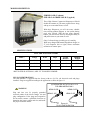
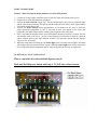
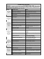
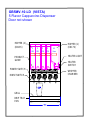
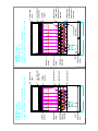
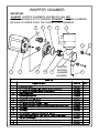
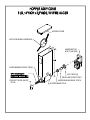
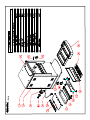
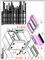
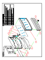
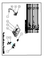
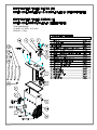
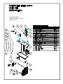
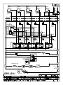
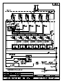
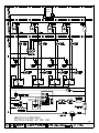
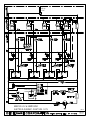
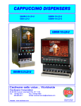
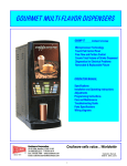
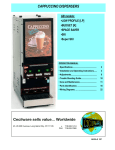
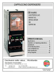
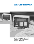
GB5MV-10-LD
GB6MP-10-LD-U
GB8MP-10-LD-U
Operation Manual
NL48P July 2005
CONTENTS
Important Owner Information_____________________________________1
Introduction____________________________________________________1
Important Safety Instructions___________________________________2
Model Description_______________________________________________3
Specifications__________________________________________________3
Plug Configurations_____________________________________________3
Installation____________________________________________________4
Start-up Procedure______________________________________________5
Troubleshooting Guide___________________________________________6
Recommended Cleaning and Sanitizing_____________________________7
Dual Probe Liquid Level Controller______________________________8
Components Tests________________________________________________9
Hopper Assembly________________________________________________10
Whipper Chambers_______________________________________________11
Body Frame_____________________________________________________12
Electrical Chassis_____________________________________________21
Upper Door_____________________________________________________22
Lower Door_____________________________________________________23
Hot Water Tanks________________________________________________24
Electrical diagram_____________________________________________26
IMPORTANT OWNER INFORMATION
Record the model number, serial number (identification plate is located behind front door), voltage and
purchase date of your Cecilware Cappuccino Dispenser in the spaces below. Please have the information
available when calling Cecilware for assistance.
Model #:
Serial #:
Voltage:
Date of Purchase:
Business
Hours:
8:30 a.m. to 5:00 p.m.
Eastern Standard Time
Telephone:
800-935-2211; 718-932-1414
Fax:
718-932-7860
Additional information can be found by visiting our web site at www.cecilware.com
INTRODUCTION
The Cecilware 5, 6, & 8 head instant Cappuccino Dispenser is designed to meet the exact needs of the
Convenience Store atmosphere.
Cecilware has led the way in the highly profitable and growing market of Cappuccino with its GB series
of Automatic Cappuccino Dispensers. Having set the standard for reliability, Cecilware also leads the
way in variety with over 50 different models to choose from.
With the introduction of Cecilware GB5MV-10-LD, GB6MP-10-LD-U & GB8MP-10-LD-U designed
exclusively to fit the increasing demand for Cappuccino sales, the hot beverage area has become to be
known as “Destination Cappuccino.”
This manual provides the installation, safety and operating instructions for the “Destination
Cappuccino” Dispensers. We recommend all installation, operating and safety instructions appearing in
this manual be read prior to installation or operation of your Cecilware Cappuccino Dispenser. Safety
and the words WARNING or
instructions that appear in this manual after a warning symbol
CAUTION printed in bold face are very important.
WARNING means that there is the possibility of
serious injury or death to yourself or others.
CAUTION means there is the possibility of minor or
moderate injury. CAUTION without the symbol signifies the possibility of equipment or property
damage only.
Cecilware products are made with extensive research and field-testing.
inspected and tested prior to shipment.
Every unit is thoroughly
IMPORTANT SAFETY INSTRUCTIONS
IMPORTANT! Read the following important safety instructions to avoid personal injury or
death, and to avoid damage to the equipment or property.
WARNINGS
The GB8MP-10-LD-U (only) is equipped with two (2) power switches and two (2) 120 volt grounded
power cords. To avoid any injury, turn both power switches OFF. Or, unplug both power cords and allow
unit to cool completely before performing any maintenance or cleaning.
The GB5MV-10-LD and GB6MP-10-LD-U are equipped with one (1) power switch and one (1) 120
volt grounded power cord.
Plug units into properly grounded electrical outlets of the correct voltage, size, and plug configuration.
The GB8MP-10-LD-U (only) requires two (2) separate dedicated outlets.
If the plug and receptacle do not match, contact a qualified electrician to determine the proper voltage and
size and install the proper electrical outlets.
These units have no “user” serviceable parts. To avoid damage to the unit or injury to personnel, use
only Authorized Cecilware Service Agents and Genuine Cecilware Parts when service is required.
Genuine Cecilware Replacement Parts are specified to operate safely in the environment in which they
are used. Some aftermarket or generic replacement parts do not have the characteristics that will allow
them to operate safely in Cecilware equipment. It is essential to use Cecilware Replacement Parts when
repairing Cecilware equipment. Failure to use Cecilware Replacement Parts may subject operators of the
equipment to hazardous electrical voltage, resulting in electrical shock or burn.
CAUTIONS
Place the unit at the proper counter height in an area that is convenient for use. The location should be
level to prevent the unit or its contents from accidentally falling, and strong enough to support the weight
of the unit and its contents.
To avoid any injury or damage to the unit do not move or relocate the unit for cleaning.
Abrasive cleaners could scratch the finish of your unit. Use only mild, non abrasive cleaners.
MODEL DESCRIPTION
GB8MP-10-LD-U (shown)
GB5-LD-U & GB6MP-10-LD-U (typical)
These High Volume Cappuccino Dispensers will hold
double the amount of your most popular flavor along
with up to seven other flavors as well.
With these Dispensers you will not waste valuable
time refilling product Hoppers or lose profits during
peak sales periods. With the hot water dispense
button, you can increase sales by offering the ability to
add packet items to your menu as well.
Only Cecilware brings you this type of versatility.
With its top hinged and bottom hinged door design, its
27 inch footprint (left to right) allows maximum
utilization of counter space.
SPECIFICATIONS
ELECTRICAL RATING CHART
Model *
1 x 15 A
Circuit
Breaker
1 x 15 A
Shipping
Weight
130 lbs
1 x 1800 W
1 x 15 A
1 x 15 A
160 lbs
2 x 1800 W
2 x 15 A
2 x 15 A
180 lbs
Voltage
Watts
Amps
GB5MV-10-LD
1 x 120 V
1 x 1800 W
GB6MP-10-LD-U
1 x 120 V
GB8MP-10-LD-U
2 x 120 V
*HOT WATER IS OPTIONAL, ADD “W” TO MODEL NUMBER
PLUG CONFIGURATIONS
The GB8 MODEL is supplied from the factory with two (2) 120 volt electrical cords and plugs
installed. Plugs are supplied according to the application as shown in figure # 1.
(2) DEDICATED OUTLETS 120 V 15 A
FOR GB8 MODELS ONLY
WARNING
Plug unit into two (2) properly grounded
electrical outlets of the correct voltage, size and
plug configuration. If the plugs and receptacles
do not match, contact a qualified electrician to
determine the proper voltage and size and install
the proper electrical outlets.
NEMA 5-15R
NEMA 5-15P
NEMA 5-15R
NEMA 5-15P
Figure # 1
PLUG CONFIGURATION
UNPACKING INSTRUCTIONS
Carefully unpack the Cappuccino Dispenser Unit and inspect immediately for shipping
damage. Your Cappuccino Dispenser Unit was shipped in a carton designed to give it
maximum protection in normal handling. It was thoroughly inspected before leaving the
factory. In case of damage, contact the shipper.
DESCRIPTION AND LOCATION OF COMPONENTS
Note: Refer to Illustrations for description and location of COMPONENTS and CONTROLS.
1. HOPPERS. To remove the hoppers simply swing the top compartment door open and lift out. To
reposition the canisters in the compartment, slide the canister base back until the ¼" pin at the
bottom of the base falls into the positioning hole of the compartment base.
2.
RINSE SWITCHES.
See diagrams inside this manual for the location of rinse switches for each individual model.
In the RINSE position they disengage the hopper motors and allow only water to be
dispensed. They are used for flushing out the Whipper Chambers and to adjust the water dispense
valves for proper flow rates.
3. HEATER SWITCHES.
See diagrams inside this manual for the location of heater switches for each individual model.
Their primary function is to shut off the heating elements during the initial priming, start up
operation of the machine, or whenever the tank is being drained for service.
4. POWER SWITCHES.
See diagrams inside this manual for the location of power switches for each individual model.
They control all power to the unit including the heater elements.
Note: The Power and Heater Switches are independent of each other. Both switches must
be OFF in order for the unit to be completely shut down.
Note: The Power Switches and Heater Switches must be ON in order for the elements to
operate.
INSTALLATION INSTRUCTIONS
WATER INLET CONNECTION:
This equipment is to be installed to comply with the applicable Federal, State, or Local plumbing
codes having jurisdiction. In addition:
WATER CONNECTION:
GB8MP-10-LD-U: There are two (2) Water Connections. (2) ¼ inch Flare Water Inlet Fittings are
located on the left and right side in the back of unit.
GB5MV-10-LD, & GB6MP-10-LD-U: There is one (1) Water Connection, (1) ¼ inch Flare Water
Inlet Fitting located on the back of unit.
An approved back flow prevention device, such as a Double Check Valve should be installed between the unit
and the water supply.
HIGHLY RECOMMENDED:
A WATER SHUT-OFF VALVE and A WATER FILTER, preferably a combination Charcoal/Phosphate Filter, to
remove odors and inhibit lime and scale build up in the machine.
Note: In areas with extremely hard water, a water softener must be installed in order to prevent
malfunctioning of the equipment and in order not to void the warranty.
START-UP PROCEDURE
Caution: Make sure that the Heater Switches, are in the OFF position.
1. Connect the ¼ inch copper waterlines to the ¼ inch flare water inlet fittings of the valves.
2. Plug the power cords into dedicated receptacles.
3. Activate the Power Switch (Toggle Up). The door display panel, the red power indicator lights
and the green dispense buttons will light up and the tanks will start filling. Allow approximately
4-5 minutes for the tanks to fill.
4. Activate the Heater Switch. Allow approximately 10-30 minutes for the water to reach the
proper dispensing temperature of 190° F. The heat up time will depend on the water inlet
temperature, the input voltage and the wattage of the elements in the water tanks.
5. Place a cup under the dispense nozzle, press and hold the dispense switch for 6 seconds. The unit
will dispense water at the rate of 1 oz. per second. Repeat it several times to check for consistent
output. Repeat same for the other dispense switches. This procedure checks that the dispense
valves are not “air-locked.”
6. While the water tanks are heating up, the heater light comes on. Remove the hoppers, load them
with product and reposition them back in place. When the heater light turns off, the water tanks
have reached their proper temperature and are ready to dispense the first cup of Cappuccino.
TO DIPENSE A CUP OF CAPPUCCINO:
Place a cup under the selected drink dispense nozzle.
Push and hold dispense button until cup is 2/3 full, then release button.
TROUBLESHOOTING GUIDE
WARNING: To reduce the risk of electrical shock, DISCONNECT POWER CORDS before repairing
or replacing any internal components of the unit. Before any attempt to replace a component be sure to
check all electrical connections for proper connection.
PROBLEM
1
Light display
not lit.
PROBABLE CAUSE
A Dispensing unit unplugged.
REMEDY
Reconnect dispensing unit.
B No power from Terminal Block.
Check the Terminal Block for loose wire.
C Defective Bulb.
D Defective Ballast.
Replace Bulb.
Replace Ballast.
E Loose Bulb in socket.
Make sure bulb is seated properly in socket.
A Water supply OFF.
2
No water when B Clogged inlet screen (Water Inlet Valve).
Rinse Switch is
C Inoperative Water Inlet Valve.
ON.
D Loose electrical connection.
A No product in Canister.
3
No product
B Auger not working.
when Dispense
C Damaged, loose, or missing Agitator Gear.
Button is
D Inoperative Auger Motor or Relay.
pressed
E Canister outlet clogged.
F Faulty Coupling.
A Leaking Water Inlet Valve.
4
Water does not
shut off.
Water keeps B Inoperative Dispense Switch.
dispensing.
C Inoperative Rinse Switch.
D Clogged/stuck Water Dispense Valve.
5
No water is
going into tank
at all.
6
Water will not
stop flowing into
water tank.
7
Water is not
heating up in
water tank.
A Water Inlet Valve malfunction.
Turn water ON.
Disconnect water line and clean inlet screen.
Check connection, if needed replace Valve.
Check all electrical connections.
Add product.
Engage Hopper/Nut to Motor Gear.
Replace Agitator Gear.
Check connections of Motor, Relay and/or Switch, if
needed replace components.
Clean Hopper.
Replace damaged Coupling components.
Clean/check Water Inlet Valve fittings. Replace Water
Inlet Valve
if needed.
Check Switch connections. Replace Dispense Switch if
needed.
Check Rinse Switch connections.
Replace Rinse Switch if inoperative.
Clean or unclog Water Dispense Valve.
Replace Dispense Valve if inoperative.
Check Solenoid. Replace if necessary.
B Dual Probe malfunction.
Check Probe. Replace if necessary.
C Dual Probe Liquid Level Controller malfunction. Check Controller. Replace if necessary.
A Dual Probe malfunction.
B Solenoid (Water Inlet Valve) malfunction.
Check Probe. Replace if necessary.
Check Solenoid. Replace if necessary.
C Dual Probe Liquid Level Controller malfunction. Check Controller. Replace if necessary.
A Heater Switch is OFF.
B Thermostat is OFF.
C Loose connection on Thermostat.
Turn Heater Switch ON.
Turn Thermostat ON.
D Hi-Limit Temperature Switch is defective
Make sure all wires and terminals on Thermostat are
tight.
Replace the Hi-limit switch.
E Heater is burned out or defective.
Replace the Heater.
Model L690A (Rev. B) Dual Probe Liquid Level Controller
Overview - The L690A is a Dual Probe Liquid Level Controller designed to maintain a specific level
of water in the tank. This device utilizes two level probes for increased reliability. Independent
maximum fill timers are incorporated in the controller for overflow protection.
Operation - When a fill problem occurs, the Dual Probe Liquid Level Controller turns OFF power to
the fill valves and remains OFF until the power input is reset (i.e. turn power switch off then back
on).
Low Level Probe - When the Low Level Probe detects the absence of water for two seconds, the
Controller immediately opens the Fill Valve. When the Low Level Probe detects the presence of
water the Controller immediately closes the Fill Valve.
High Level Probe - When the High Level Probe detects the absence of water the Controller
immediately turns ON and the Low Level Probe is allowed to control the Fill Valve. When the High
Level Probe detects the presence of water for 1.5 seconds the Controller turns OFF power, which
closes the Fill Valve.
Maximum Fill Timers – On the first fill, the unit will only allow 15 minutes of continuous filling if
neither of the Level Probes has detected the presence of water since power has been applied (i.e. first
fill). Once the presence of water has been detected the unit will only allow 10 minutes of continuous
filling to prevent flooding. If the duration of continuous filling exceeds the allotted time then a Fatal
Error is generated, which closes the inlet valve.
Status LED – Located on the Controller, this indicator is turned ON for one second after power is
applied to indicate a functioning unit. The indicator will blink when the High Level Probe detects
water to signify a warning. During a Fatal Error the indicator will be ON continuously.
1. ROTATE PRODUCT GUIDES UP, REMOVE HOPPERS AND
REFILL WITH PRODUCT.
2. REPLACE HOPPERS, ROTATE PRODUCT GUIDES DOWN.
3. EMPTY DRIP TRAY.
4. SANITIZE* ALL EXTERIOR SURFACES.
1. RINSE WHIPPER CHAMBERS
- POSITION PAN UNDER DISPENSE TUBES.
- MOVE RINSE SWITCH TO "RINSE".
- PUSH AND HOLD EACH DISPENSE BUTTON 3 TO 5 SEC.
- MOVE RINSE SWITCH TO "SERVE".
2. EMPTY DRIP TRAY WASH, RINSE, AND SANITIZE*
1. PRODUCT HOPPER CLEANING
- ROTATE PRODUCT GUIDES UP, REMOVE HOPPERS FROM MACHINE.
- EMPTY POWDER INTO PANS.
- PULL OFF PRODUCT GUIDES.
- REMOVE AGITATOR WHEELS.
- UNSCREW AND REMOVE FRONT AND BACK AUGER LOCKS.
- REMOVE AUGER.
- WASH, RINSE, SANITIZE*, AND AIR DRY ALL SMALL PARTS.
-WASH & SCRUB HOPPERS AND AGITATOR WHEEL RECESSES WITH BRISTLE BRUSH
- REASSEMBLE ALL HOPPERS.
- POUR POWDER INTO HOPPERS.
- INSTALL ALL HOPPERS INTO UNIT.
2. WHIPPER CHAMBER CLEANING
- REMOVE DISPENSE CAPS BY TURNING AND LIFTING.
- REMOVE MIXING BOWLS BY LIFTING AND PULLING.
- REMOVE PRODUCT TUBES BY PULLING DOWN.
- TWIST OFF WHIPPING CHAMBERS CLOCKWISE.
- PULL OFF WHIPPER BLADES.
- TWIST OFF WHIPPER CHAMBER MOUNTS CLOCKWISE.
- REMOVE O-RINGS.
- REMOVE TRAY BY PULLING LEVERS DOWN.
- REMOVE BOTH POWDER TRAYS BY PULLING LEVERS OUT.
- WASH, RINSE, AND SANITIZE SMALL PARTS AND
INTERIOR MACHINE SURFACES.
- REASSEMBLE ALL SMALL PARTS.
* SANITIZING:
All sanitizing agents in the food zone must comply with 21 CFR 178.1010.
All food dispensing units should be sanitized periodically. All parts to be sanitized must be cleaned first.
To prepare a sanitizing solution:
ADD 2 TSP. OF LIQUID CLOROX BLEACH (5.25% CONCENTRATION) TO 1 GALLON OF WATER AT ROOM TEMPERATURE (70°- 90°F).
Note: Always start with a unopened bottle of Clorox Bleach since the solution from an opened bottle has a short life span.
-Soak all parts for a minimum of 3 min. in the sanitizing solution.
-Let all sanitized parts drain and dry naturally. DO NOT WIPE THEM DRY.
-Before using the sanitized unit (or parts) with food stuffs, rinse all parts thoroughly with water.
GB5MV-10-LD (VISTA)
5 Flavor Cappuccino Dispenser
Door not shown
HOPPER (4)
(CD185)
PRODUCT
GUIDE
POWER SWITCH
RINSE SWITCH
GRILL
DRIP TRAY
PAN
5
Lbs
5
Lbs
5
Lbs
5
Lbs
10
Lbs
HOPPER (1)
(CD179)
HEATER LIGHT
HEATER
SWITCH
WHIPPER
CHAMBER
DRIP TRAY
PAN
GRILL
SLANTED
WHIPPER
CHAMBER
PRODUCT
GUIDE
HOPPER
(CD185)
5
Lbs
5
Lbs
5
Lbs
21.5"
5
Lbs
5
Lbs
10
Lbs
RINSE SWITCH
HEATER LIGHT
POWER SWITCH
DRIP TRAY
PAN (2)
GRILL
WHIPPER
CHAMBER
PRODUCT
GUIDE
HOPPER
(CD185)
5
Lbs
5
Lbs
5
Lbs
5
Lbs
5
Lbs
5
Lbs
HOT WATER
(OPTIONAL)
27.0"
5
Lbs
10
Lbs
HEATER LIGHT
POWER SWITCH
RINSE SWITCH
RIGHT SIDE
HEATER LIGHT
POWER SWITCH
RINSE SWITCH
LEFT SIDE
HOPPER
(CD180)
GAS SPRING (2)
DOOR LIFTS
GAS SPRING (2)
DOOR LIFTS
HOPPER
(CD180)
UPPER DOOR
OPEN
GB8M-10-LD-U
GB8MP-10-LD-U
8 Flavor Cappuccino Dispenser
Upper Door open, Lower Door not shown.
UPPER DOOR
OPEN
GB6M-10-LD-U
GB6MP-10-LD-U
6 Flavor Cappuccino Dispenser
Upper Door open, Lower Door not shown.
WHIPPER CHAMBER
IMPORTANT:
SLANTED WHIPPER CHAMBERS (SEE BELOW) ARE NOT
INTERCHANGEABLE WITH STANDARD STRAIGHT WHIPPER CHAMBERS.
BE SURE TO ORDER USING THE CORRECT PART NUMBERS.
6
8
9
12
3
11
5
S L A
N
T
E
D
7
1
4
13
2
SLANTED
WHIPPER
CHAMBER
MARKING
ITEM
1
2
2
4
7
7
11
12
IMPELLER (1 FLAT) USE W/ CD75A)
IMPELLER (2 FLATS) USE W/ CD75A OR CD350
10
2
1
1
1
1
2
1
1
1
1
1
1
2
1
1
1
HOPPER COVER
AGITATOR WHEEL W/SPRINGS
AUGER MOTOR
#CD175 (90 RPM)
AUGER BUSHING FRONT CD306
NUT CD278 [2]
BEVELLED SOCKET CD271
PRODUCT GUIDE, SHORT
CD70A
AUGER BUSHING-BACK CD279
HOPPER BASE CD140
HOPPER COVER
AGITATOR WHEEL W/SPRINGS
AUGER MOTOR
#CD175 (90 RPM)
AUGER BUSHING FRONT CD306
NUT CD278 [2]
BEVELLED SOCKET CD271
PRODUCT GUIDE, SHORT
CD70A
AUGER BUSHING-BACK CD279
HOPPER BASE CD140
BODY ASS'Y
GB5MV-10-LD (Vista)
ITEM
DESCRIPTION
P/N
QTY
DOOR ASS'Y
GB5MV-10-LD (Vista)
ITEM
DESCRIPTION
P/N
QTY
2
1
3
4
DOOR ASS'Y
GB6MP-10-LD-U (Panorama)
GB8MP-10-LD-U (Panorama)
5
6
11
10
9
8
7
8
9
10
11
ITEM
NO.
1
2
3
4
5
6
GB6MP
P/N
SK61A
SK65A
SK60A
SK50A
M903A
M904A
NN13A
L455A
MA05A
M981A
B216A
CE82A
QTY
1
1
1
1
1
1
1
6
1
2
2
2
GB8MP
P/N
QTY
SK43A
1
SK45A
1
SK42A
1
SK44A
1
M915A
1
M916A
1
NN52A
1
L455A
8
MA26A
1
M981A
3
B216A
3
CE80A
3
7
DESCRIPTION OF COMPONENTS FOR MACHINES
WITH MOLDED FRONT GB6MP AND GB8MP
INSIDE DOOR PANEL, UPPER DOOR
INSIDE DOOR PANEL, LOWER DOOR
DOOR HOUSING, UPPER
DOOR HOUSING, LOWER
MOLDED UPPER DOOR PANEL
MOLDED LOWER DOOR PA NEL
SWITCH PANEL LABEL F/ MOLDED LOWER DOOR
DISPENSE SWITCH [GREEN]
CLEAR WINDOW PANEL 0.04" THICK
TY-WRAP
LAMP HOLDER FOR UNIFIED BULB
BULB UNIFIED 120V [CE80A 240V]
ITEM
DESCRIPTION
P/N
QTY
TANK DIMENSIONS:
12" WIDE, 4.8" DEEP, 16.5" HIGH.
APPROX. 3.7 GAL.
ITEM DESCRIPTION
P/N
QTY
TANK DIMENSIONS:
15" WIDE, 6" DEEP, 18" HIGH.
APPROX. 6 GAL.
ITEM DESCRIPTION
P/N
QTY
BLK
BREW
SWITCH
BREW
SWITCH
YEL
WHT
BREW
SWITCH
BRN
WHT
BREW
SWITCH
VIO
WHT
BREW
SWITCH
RED
DISPLAY
LIGHT
ORG
WHT
WHT
BLK
DOOR UNIT
GND
MAIN UNIT
DISPENSE
VALVE
DISPENSE
VALVE
DISPENSE
VALVE
RINSE SWITCH
A1
A2
43 NO
44NO
31 NC
32NC
21NC
22 NC
13 NO
14NO
BLK
DISPENSE
VALVE
GND
DISPENSE
VALVE
AUGER
AUGER
AUGER
AUGER
CONTACTOR
AUGER
WHIPPER
WHIPPER
BLK
BLK
RELAY
RELAY
WHIPPER
BLK
WHIPPER
BLK
RELAY
WHIPPER
BLK
RELAY
RELAY
BLU
L1
WATER INLET
VALVE
LIQUID LEVEL CONTROL
FAN
L1
WATER LEVEL
PROBES
WATER
TANK HEATER 1.7KW
L1
N
HI-LIMIT
5-15R
W
15A-1.7KW
HEATER SWITCH
POWER
SWITCH
5-15P
W
G
G
GB5-LD-U
THERMOSTAT
L1
GND
GB6M-10-LD-U
DISPLAY
LIGHTS
LIQUID LEVEL CONTROL
WATER LEVEL
PROBES
WATER
GB8M-10-LD-U & GB8M10WLD
ELECTRICAL DIAGRAM - LEFT SIDE - 120V
REV A
NE195
SHEET 1 OF 2
DISPLAY
LIGHT
LIQUID LEVEL CONTROL
WATER LEVEL
PROBES
WATER
GB8M-10-LD-U & GB8M10WLD
ELECTRICAL DIAGRAM - RIGHT SIDE - 120V
REV A
NE195
SHEET 2 OF 2