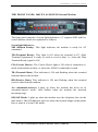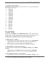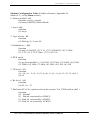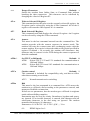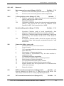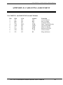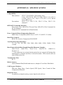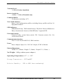
1
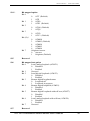
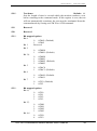
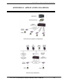
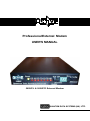
Professional External Modem USER'S MANUAL 560UF/L & 560UF/D External Modem QUANTUM DATA SYSTEMS (HK) LTD. ACTIVE Professional External Modem USER`S MANUAL For Models: 560UF/L & 560UF/D The contents of this manual are subject to change without prior notice. Quantum Data Systems (H.K.) Ltd. shall not be held liable for technical or editorial omissions or errors made herein; nor for incidental or consequential damages resulting from the furnishing, performance or use of this material. Trademarks n Hayes - Hayes Microcomputer Products, Inc. n MNP - Microcom Inc. n IBM - International Business Machines Inc. n Telix - EXIS Inc. n BTLZ - British Telecommunications. n Mirror III - Softklone Inc. n Procomm - Datastorm Technologies, Inc. n Homefax 2 - HongKong Telecom. n Active, QFax & QCom - Quantum Data Systems (H.K.) Ltd. n Other product names mentioned herein are registered trademarks of their own companies. Edition 2.0 September, 2003 1999 Quantum Data Systems (H.K.) Ltd. Quantum Data Systems (H.K.) Ltd. Unit 9, 7th Floor, Block B, Hoi Luen Industrial Centre, 55 Hoi Yuen Road, Kwun Tong, Hong Kong Tel : (852) 2304-1199 Fax : (852) 2341-3292 Web site : http://www.quantum.com.hk E-mail : [email protected] WARNING - AUSTRALIAN USERS This FAX/Modem has been tested with Bitcom, Bitware for windows and fully complies with AUSTEL Technical Standards if the following conditions are followed : 1 THE NUNMBER OF RE-DIAL MUST NOT BE SET TO GREATER THAN 3 2. THE MODEM MUST NOT BE CONFIGURED TO THE BELL MODE OF OPERATION Software packages other than the above, or any other configurations defined by the user, were not tested and may result in the modem being operated in a non-compliant manner. CONSEQUENTLY, THERE WOULD BE NO PERMIT IN FORCE FOR THIS EQUIPMENT, AND THE TELECOMMUNICATIONS ACT 1991 PRESCRIBES A PENALTY OF $12,000 FOR CONNECTION OF NON-PERMITTED EQUIPMENT. For external modem, users must only use an ACTIVE AC Adaptor, Model No. : 4824-1485-3AC. (Approval No. : N12430) WARNING - SWEDISH USERS After the country code or the digit 0 from a PBX, users must use a W to indicate dial tone detection. It is not allowed to use pause (comma) instead of dial tone detection (W). TABLE OF CONTENTS CHAPTER 1. INTRODUCTION 1 CHAPTER 2. INSTALLATION 2 CHAPTER 3. LEASED LINE OPERATION APPENDIX A. AT COMMANDS 11 APPENDIX B. RESULT CODES 24 APPENDIX C. S REGISTERS 26 APPENDIX D. CABLE PINS ASSIGNMENT 36 APPENDIX E. SPECIFICATIONS 37 APPENDIX F. APPLICATION EXAMPLES 39 APPENDIX G. LED CONFIGURATION CHART FOR LEASED LINE 40 9 CHAPTER 1. INTRODUCTION CHAPTER 1. INTRODUCTION OVERVIEW Congratulations on your purchase of ACTIVE Professional External Modem. The modem equips with V.42/MNP2-4 error control, V.42bis/MNP5 data compression as well as 14400bps facsimile functions. It incorporates the latest in advanced communications technology providing maximum functionality and 100% data transfer accuracy at the highest data transfer speed. Active External modem is compatible with many terminal servers and multiport serial adapters available world wide, such as Cisco 2500 series, Computone, Chase Research, Perle Specialix, Nortel Bay Networks, Lantronix, 3 Com, Moxa, Digi Board, Systech, Gts, Huawei , etc. This guide describes the following models : n 560UF/D :External dial up modem n 560UF/L: External leased-line modem ACTIVE Professional External Modem User’s Manual 1 CHAPTER 2. INSTALLATION CHAPTER 2. INSTALLATION Carefully unpack the product package that you have received and check the contents as following: n The modem equipment n Telephone cable n 5V DC power adapter & power cable n Modem cable: 9 pins male to 9/25 pins female n Digital User’s Manual (Download from www.quantum.com.hk) The Rear View: 560UF/L & 560UF/D External Modem Line Jack Only use the middle 2 pins (Pin 2 & Pin 3) to connect to the “Line” jack of the modem. SERIAL PORT For pin assignment, please refer to Appendix D Install your external modem 1. Power off the computer or terminal and the modem. 2. Modem cable: Connect the 9-pins male modem cable to the “Serial Port” of the modem. Tighten the screws. Connect the other end of the modem cable ( 9-pins & 25-pins female) to the serial port of your Computer or terminal. Tighten the screws. 3. Telephone Line cable: Connect one end the phone cable to the “Line” jack of the modem and the other end to the telephone line or leasedline jack.. 4. Power Adapter: Connect the 5VDC power adapter jack to the “5V DC” port of the modem. The other end of the power cable to the 110/220 power socket. 5. Power on the computer or terminal and the modem. Configure the modem by issuing the appropriate AT commands or using the front panel switches. 6. The modem is ready for operation. ACTIVE Professional External Modem User’s Manual 2 CHAPTER 2. INSTALLATION THE FRONT PANEL: 560UF/L & 560UF/D External Modem The front panel consists of seven light indicators, a 7 segment LED and five switch buttons which are explained as follows: Seven light indicators: MR (Modem Ready): This light indicates the modem is ready for AT command. TR (Terminal Ready): This light is ON when the terminal or PC (Data Terminal Equipment) is ready to send or receive data, i.e. when the Data Terminal Ready signal is ON. CD (Carrier Detect): The Carrier Detect light is ON when a connection is made with another modem, or when the AT&C0 command is issued. TD (Transmit Data): This indicator is ON and flashing when the terminal transmits data to the modem. RD (Receive Data): This indicator is ON and flashing when the terminal receives data from the modem. AA (Automatic-answer): Lights up when the modem has been set to automatic-answer mode. Also flashes when the modem has detected incoming rings. OH (Off Hook): Lights up when the modem uses the telephone line (in the data mode). The OH indicator goes out when the modem hangs up the phone line or when it is in the Talk mode. ACTIVE Professional External Modem User’s Manual 3 CHAPTER 2. INSTALLATION A 7-segment LED (optional) Monitor the line speed. The speed may fall down or step up depending on the telephone line quality. 9 - 33600 bps 8 - 31200 bps 7 - 28800 bps 6 - 26400 bps 5 - 24000 bps 4 - 21600 bps 3 - 19200 bps 2 - 16800 bps 1 - 14400 bps 0 - 12000 bps A - 9600 bps C - 7200 bps E - 4800 bps F - 2400 bps H - 1200 bps L - 600 bps P - 300 bps F. - fax mode Five switch buttons: 1. Normal / Config. Select between Normal and Configuration mode. ‘POP’ position is the Normal mode, ‘PUSH’ position is the Config. mode. In Config. mode, the modem can be configured through the front panel switches. After configuration, the modem must be set back to Normal mode. 2. Menu (menu 0 – menu C) a. If the modem is in Config. mode, this switch acts as a menu pointer. Toggle this switch causes the modem to increase the pointer by 1. (please refer to the section ‘modem configuration table’). b. If the modem is in Normal mode, this switch has no function. 3. T/D(Talk/Data) or Function (Function) Operation of this switch depends on the Normal / Config. and the Menu switches. If the modem is in Config. mode, this switch acts as a Function pointer. (please refer to the section ‘modem configuration table). 4. O/A (Originate/Answer) or En (Enable) The operation of this switch depends on the Normal / Config. switch. ACTIVE Professional External Modem User’s Manual 4 CHAPTER 2. INSTALLATION a. If the modem is in Normal mode, it acts as a O/A switch. Toggle this switch causes the modem to change from Originate mode to Answer mode and the LED segment displays ‘A.’ for answer mode, or ’O.‘ for Originate mode. b. If the modem is in Config. mode, it acts as an Enable switch. Toggle this switch causes the modem to execute the selected features and LED segment shows 'U'. The features (except menu 7) were saved to NVM profile 0 automatically (please refer to the section ‘modem configuration'). 5. Reset switch – Press to reset the modem during unexpected software hung-up. Use T/D Switch to dial 1. Store a 36-digit dial string in the specified entry (n =1-3) for later dialing (AT&Zn=<T or P><tel. no> , n=1-3, i.e AT&Z1=T123456 for tone dial, AT&Z1=P123456 for pulse dial). 2. Set Normal / Config. Switch to PUSH position for configuration mode. 3. Toggle the Menu Switch to the desired Menu 7. 4. Toggle the FunctionSwitch to the desired Function (n=1-3). 5. Press the En Switch to execute the selected features. The character ‘U’ is shown on the LED segment. 6. Set Normal / Config. Switch to POP position. 7. Press the T/D Switch to dial the specific entry (Dial number previously stored in directory location n using AT&Zn). ACTIVE Professional External Modem User’s Manual 5 CHAPTER 2. INSTALLATION Modem Configuration Table (Further reference: Appendix G) Menu (0-C, set by Menu switch) 0 Factory default - &F function (set by switch) (0)Auto,(1)MNP,(2)Direct Mode. 1 Asyn - &Q function (0) Asyn 2 Type of line - &L function (0) Dial up, (1) 2 wire LL 3 Modulation - +MS function (0) auto (1) bell103, (2) V.21, (3) V.22/bell212, (4) V.22bis (5) V.23, (6) V.32/V.32bis, (7) V.34/V.34+ 4 DTE speed function (0) get from profile 0, (1) 115200, (2) 57600, (3) 38400, (4) 19200, (5) 14400, (6) 9600, (7) 4800, (8) 2400, (9) 1200, (A) 300 5 TX level - S91 function (0) –10, (1) – 2, (2) – 4, (3)-6, (4) –8, (5) – 9, (6)-11, (7)-12, (8)-13, (9)-14 6 Rx level - %R function (0)-43, (1) –33 7 Dial stored Tel. No. (please refer to the section ‘Use T/D Switch to dial’ .) function (0) Normal (1) Dial tel. no(stored by AT&Z1) (2) Dial tel. no(stored by AT&Z2) (3) Dial tel. no (stored by AT&Z3) ACTIVE Professional External Modem User’s Manual 6 CHAPTER 2. INSTALLATION 8 Smart/Dumb mode - &A function (0) smart, (1) dumb 9 Compression control - %C function (0) Enables both MNP5 and V.42bis data compression (1) Disables data compression (2) Enables MNP5 data compression (3) Enables V.42bis data compression A DTE/DCE Flow control - &K function (0) Enables RTS/CTS flow control (1) Disable flow control (2) Enables XON/XOFF flow control (3) Enables transparent XON/XOFF flow control (4) Enables both RTS/CTS and XON/OFF flow control (default for fax mode) C Save to NVM memory - &W function (0) profile 0, (1) profile 1 Modem Configuration through front panel (also refer to modem configuration table) To configure your modem through modem front panel switches, please follow the procedures below: 1. 2. 3. 4. 5. 6. After the installation as described in section ‘Install your modem’, Set Normal / Config. Switch to PUSH position for configuration mode. Toggle the Menu Switch to the desired Menu (0 to C). The state is shown on the LED segment. Toggle the Function Switch to the desired Function. The state is shown on the LED segment. Press the Enable Switch to update the selected features. The character ‘U’ is shown on the LED segment. (The updated features were saved to NVM memory profile 0 automatically except menu 7). To finish configuration by setting the Normal / Config. Switch to POP position. ACTIVE Professional External Modem User’s Manual 7 CHAPTER 2. INSTALLATION Example to set up DTE speed 57600 bps and modulation V.22 bis, 1. 2. 3. 4. 5. Set Normal / Config. Switch to PUSH position for Config. mode. Set desired DTE speed 57600 bps Method: Toggle the Menu Switch to Menu 4 (DTE speed menu), the digit ‘4’ is shown on the LED segment. Then toggle the Function Switch to Function 2 (speed 57600 bps is selected), the digit ‘2’ is shown on the LED segment. Then press the Enable Switch to update the DTE speed, The character ‘U’ is shown on the LED segment and all parameters will be saved to profile 0 automatically. Set modulation V.22 bis Method: Toggle the Menu Switch to Menu 3 (modulation menu), the digit ‘3’ is shown on the LED segment. Then toggle the Function Switch to Function 4 (V.22 bis is selected), the digit ‘4’ is shown on the LED segment. Then press the Enable Switch to update the modulation setting, the character ‘U’ is shown on the LED segment and all parameters will be saved to profile 0 automatically. If more settings are required (i.e tx level, flow control, etc), repeat the above steps. The above features were saved to profile 0 automatically). To finish configuration by setting the Normal / Config. Switch to POP position. ACTIVE Professional External Modem User’s Manual 8 CHAPTER 3. LEASED LINE OPERATION CHAPTER 3. LEASED LINE OPERATION This chapter tells you how to establish a leased line connection in asynchronous and synchronous modes. What is Leased Line Operation? In leased line operation, two modems are directly wired together by a dedicated telephone line. The register S7 does not pose a time limit on making a data connection. One modem must be set to originate mode and the other must be set to answer mode. ACTIVE modem is designed to be used with a 2-wire / 4-wire(optional) leased line The RS-232C DTR signal must be ON to maintain the leased line data connection. If the modem detects a DTR drop during data connection, the carrier will be dropped. Once the DTR signal is restored to ON, the modem will re-start to establish data connection. The user can use the AT&D0 command to cancel the effect of DTR status on this operation. In this case, the modem will perform this operation disregard of the DTR status. Asynchronous Power-on Leased Line (POLL) Operation When the modem is set to POLL mode, the carrier is transmitted immediately upon powered up. The modem will wait for the remote carrier eternally until data connection is established. If the modem detects a loss of carrier during data connection, it will send the carrier for a re-connection automatically. The following is an example to establish a Power-on 2-wire leased line (POLL) operation, Please follow the instructions below: 1. Make proper wiring connection. 2. Prepare two modems. One modem set to Answer mode, another one set to Originate mode. Method: Set Normal / Config. Switch to POP position for Normal mode. Toggle the O/A switch to Answer mode or Originate mode. The LED segment displays ‘A.’ for Answer mode, or ‘O.’ for Originate mode. 3. Set desired DTE speed, protocol, transmission mode, flow control, etc. Method: Set Normal / Config. Switch to PUSH position for Config mode. DTE speed: For example, if 57600 bps DTE speed is required, toggle the Menu Switch to Menu 4 (DTE speed menu), the digit ‘4’ is shown on the LED segment. Then toggle the Function Switch to Function 2 (speed 57600 bps is selected), the digit ‘2’ is shown on the LED segment. ACTIVE Professional External Modem User’s Manual 9 CHAPTER 3. LEASED LINE OPERATION 4. 5. Then press the Enable Switch to update the DTE speed, The character ‘U’ is shown on the LED segment. If more setting are required (i.e transmission mode, flow control, etc), repeat the above procedures. Enable the POLL after all parameters are set. Method: Set Normal / Config. Switch to PUSH position for Config mode. Toggle the Menu Switch to Menu 2 (type of line menu), the digit ‘2’ is shown on the LED segment. Then toggle the Function Switch to Function 1 (2 wire LL is selected), the digit ‘1’ is shown on the LED segment. Then press the Enable Switch to enable POLL, the character ‘U’ is shown on the LED segment and all parameters will be saved to profile 0 automatically. To finish configuration by setting the Normal / Config. Switch to POP position. You will hear the sound of modem handshaking procedure. The sound will be on until the data connection is made. Procedure to exit the Power-On Leased Line(POLL) 1. 2. 3. 4. 5. Set Normal / Config. Switch to PUSH position for configuration mode. Toggle the T/D switch to break the handshake. Toggle the Menu Switch to Menu 2 (type of line menu), the digit ‘2’ is shown on the LED segment. Toggle the Function Switch to Function 0 (dial up line is selected), the digit ‘0’ is shown on the LED segment. Press the Enable Switch to disable POLL, the character ‘U’ is shown on the LED segment and all parameters will be saved to profile 0 automatically. AT COMMAND for Leased Line Configuration AT%On * Select answer/originate mode %O0 Selects answer mode %O1 Selects originate mode AT&Ln * Transmission line type AT&L0 Dial-up line AT&L1 2-wire Leased line (Option) AT%Rn * Select Receive sensitivity level AT%R0 Select –43dBm receive sensitivity level AT%R1 Select –33dBm receive sensitivity level ACTIVE Professional External Modem User’s Manual Default : 1 Default : 0 Default : 0 10 APPENDIX A. AT COMMANDS APPENDIX A. AT COMMANDS The PC or terminal communicates with the modem through the use of the AT commands. Your communication software will act as an interface between you and your modem. You read this chapter to customise your configuration. To issue these industry-standard "AT" commands, first load a communication software package and then enter Terminal or Interactive Mode (Refer to your communication software manual). All command lines must begin with the ASCII letters "AT" and end with "<Enter>" except for the A/ command and escape characters (default +++), which will be discussed later. The letters "AT" are sometimes referred to as an attention code. This command indicates to the modem that one or more commands are to follow. The "AT" and all following alphabetic characters may be in upper or lower case. AT must be entered in the same case such as "AT" or "at". "At" or "aT" are not permitted. A series of commands can be grouped in a single line. The commands can be entered in a string with or without spaces for readability. Spaces within or between commands are ignored. The maximum number of characters in any command line is 39 (including “AT”). During the entry of a command, the backspace key can be used to correct errors with the exception of “AT”. If a syntax error is found anywhere in a command line, the remainder of the line will be ignored and the ERROR result code will be returned. Most commands entered with parameters out of range will not be accepted and the ERROR result code will be returned. This chapter lists all the commands used to configure the modem. It includes standard Hayes AT commands, Hayes V-series commands and extended commands to control ACTIVE modem. DESCRIPTION OF AT COMMANDS The symbol * means command setting may be stored in one of the two user profiles with the AT&Wn command. A/ Re-execute command Re-executes the most recent AT command string. The principle application of connect due to a busy line, no answer, or a wrong number. This command must appear alone in a command line and must be terminated by the “/” character. (A <Enter> should not be entered to end the command.) ACTIVE Professional External Modem User’s Manual 11 APPENDIX A. AT COMMANDS +++ Escape Characters Default : + Switch the modem from Online State to Command State without breaking the data connection. This character can be redefined by changing the value in S Register S2. AT=x Write to Selected S Register This command writes the value x to the currently selected S register. An S register can be selected by using the ATSn command. All of the Sregister will return the OK response if x is a number. AT? Read Selected S Register This command reads and displays the selected S register. An S register can be selected by using the ATSn command. ATA Answer This must be the last command entered into the command line. The modem proceeds with the connect sequence in answer mode. The modem will enter the connect state after exchanging carrier with the remote modem. If no carrier is detected within a wait period specified in register S7(default = 50 seconds), the modem will disconnect. Any character may be entered via the DTE during the connect sequence to abort the command. ATBn * Set ITU-T or Bell mode Default : 0 ATB0 Selects ITU-T V.22 and V.21 standards for communication at 1200 and 300bps ATB1 Selects Bell 212A and 103 standards for communication at 1200 and 300bps ATCn Carrier control Default : 1 This command is included for compatibility only, and has no effect other than returning a result code. ATC1 ATDn Normal transmit carrier switching Dial This must be the last command in a command line. ATD causes the modem to go off-hook, dial according to the parameters entered, and attempt to establish a connection. If there are no parameters, then the modem goes off-hook in originate mode without dialling a number. Punctuation may be used for clarity. Parentheses, hyphens and spaces are ignored. If an invalid character is entered, that character and all subsequent characters in the dial string are ignored. The modem truncates dial strings to 36 characters. Parameters: 0-9 A B C D * # L P T R ! @ W , ; ^ S=n 0-9 DTMF digits 0 to 9 ACTIVE Professional External Modem User’s Manual 12 APPENDIX A. AT COMMANDS A-D DTMF digits A ,B,C and D. These digits may be prohibited in some countries * The "star" digit (tone dialling only) # The "gate" digit (tone dialling only) J Perform MNP 10 link negotiation at the highest supported speed for this call (Optional) K Enable power level adjustment during MNP 10 link negotiation for this call (Optional) L Dials the last dial string that was dialled P Use pulse dialling T Use DTMF dialling R Reverse mode. Allow the modem to call an originate-only modem by forcing the call into "answer mode". Must be entered as the last character of the command string (optional). ! Cause the modem to go on-hook for a time defined by the value in S29 and then off-hook. @ Cause the modem to listen for 5 seconds of silence W Wait up to the period of time specified in register S7 for dial tone before dialling , Pause for the value specified by register S8 during dial ; Return to Command State after dialling ^ Turn on calling tone () Ignored, may be used to format the dial string Ignored, may be used to format the dial string <space> Ignored, may be used to format the dial string S=n Dial number previously stored in directory location n using AT&Zn command ATE * Command echo ATE0 Inhibits the echoing of commands ATE1 Enables the echoing of commands ATHn Switch-hook control Default : 0 ATH0 Cause the modem to go on-hook ATH1 If modem is on-hook, modem goes off-hook, returns an OK response, and waits for further commands ATIn Identification I0 Reports product code I1 Reports pre-computed checksum from ROM I2 Computes checksum and compares it with value stored in ROM. Reports result as OK or ERROR. I3 Reports firmware revision I4 Reports OEM defined identifier string I5 Reports Country Code parameter I6 Reports firmware revision I7 Reports modem data pump model ACTIVE Professional External Modem User’s Manual Default : 1 13 APPENDIX A. AT COMMANDS ATLn * Speaker volume ATL0 Selects low speaker volume ATL1 Selects low speaker volume ATL2 Selects medium speaker volume ATL3 Selects high speaker volume ATMn * Speaker control Default : 1 ATM0 Speaker is always off ATM1 Speaker is on during handshaking in call establishment but is turned off while the modem is receiving a carrier signal from a remote modem ATM2 Speaker is always on ATM3 Speaker goes off while the modem is receiving a carrier signal from a remote modem and while the modem is dialling. However, speaker is on during answering ATNn * Modulation handshake Default : 1 ATN0 Requires the speed of the connection be that specified by the value held in S37; if S37=0, the speed of the connection must match that at which the last AT command was issued. If the selected speed can be achieved using more than one communication standard (e.g., Bell 212A or ITU-T V.22 at 1200bps), the modem also refers the selection made with the ATB command ATN1 Permits handshaking to occur at any speed supported by both modems. Enables automode detection. The ATB command is ignored in this mode and the modem attempts only ITU-T mode connections. ATOn Return to the on-line state Default : 0 ATO0 Causes the modem to return to the data mode ATO1 Causes the modem to return to the data mode and to initiate a retrain ATP * Set pulse dial as default ATQn * Result code display Default : 0 ATQ0 Allows the modem to send result codes to the DTE ATQ1 Prohibits the modem from sending result codes to the DTE ATSn Establish S register n as the default register ATSn? Reading S registers Reads the contents of the S register. All the S registers may be read. ATSn=x Writing to S registers Writes the value of x to the specified S register n ACTIVE Professional External Modem User’s Manual Default : 2 14 APPENDIX A. AT COMMANDS ATT * Set tone dial as default ATVn * Result code form (message control) Default : 1 ATV0 Allows short form (numeric) result codes to be sent ATV1 Allows long form (verbose) result codes to be sent ATWn * Negotiation progress reporting Default : 0 ATW0 Error-correction call progress not reported ATW1 Error-correction call progress reported ATW2 Error-correction call progress not reported. CONNECT XXXX message reports DCE speed. ATXn * Extended result codes Default : 4 ATX0 Modem ignores dial tone and busy signal. Sends CONNECT message when a connection is established by blind dialling ATX1 Modem ignores dial tone and busy signal. Sends CONNECT XXXX message reflecting bit rate when a connection is established by blind dialling ATX2 Modem ignores busy signal but waits for dial tone before dialling. If dial tone is not detected within 5 seconds, the NO DIAL TONE message is sent. Sends CONNECT XXXX message reflecting bit rate when a connection is established. ATX3 Modem ignores dial tone. Sends BUSY message if a busy signal is detected. Sends CONNECT XXXX message reflecting bit rate when a connection is established by blind dialling. ATX4 If dial tone is not detected within 5 seconds, sends NO DIAL TONE message. If busy signal is detected, sends BUSY message. Sends CONNECT XXXX message reflecting bit rate when a connection is established. ATYn * Control long space disconnect ATY0 Disables long space disconnect ATY1 Enables long space disconnect Default : 0 ATZn Reset Restore the active configuration with the user profile ATZ0 Soft reset and restore stored profile 0 ATZ1 Soft reset and restore stored profile 1 Default : 0 AT&An * Handshake Abort Option Default : 1 AT&A0 Disables the user abort during handshaking. Once the dialling string is entered or answer is initiated, the handshaking cannot be aborted. Only dropping DTR signal (except &D0 option) and pressing T/D switch can abort the operation. AT&A1 Enables the user abort during handshaking. Anytime during ACTIVE Professional External Modem User’s Manual 15 APPENDIX A. AT COMMANDS a handshaking sequence, the call and answer can be aborted by receiving any character from DTE. AT&Cn * RS232-C DCD option Default : 1 AT&C0 DCD is ON regardless of the state of the data carrier from the remote modem AT&C1 DCD follows the state of the data carrier from the remote modem AT&Dn * RS232-C DTR option Default : 2 Determines actions taken by the modem in relation to the DTR signal of the serial port. The action for the event that follows DTR drop indicated in the following table: &D0 &D1 &D2 &D3 &Q0 NONE 2 3 4 &Q1 1 2 3 4 &Q2 3 3 3 3 &Q3 3 3 3 3 &Q4 1 2 3 4 &Q5 NONE 2 3 4 &Q6 NONE 2 3 4 1 2 3 4 Modem disconnects and sends OK result code Modem goes into command mode if ni data mode and sends the OK result code Modem disconnects, sends the OK result code, and disables auto answer while DTR is off Modem performs a warm start (i.e., same as ATZ command) AT&Fn Restore factory configuration Default : 0 &F0 Recalls fa ctory default as V.42bis auto-reliable mode &F1 Recalls factory default as MNP 5 auto-reliable mode &F2 Recalls factory default as DIRECT mode AT&Gn * Set guard tone AT&G0 No guard tone AT&G1 550 Hz guard tone AT&G2 1800 Hz guard tone AT&Jn * Telephone jack selection Default : 0 This command is only included for compatibility and performs no function. AT&J0 Performs no function AT&J1 Performs no function AT&Kn * DTE/modem flow control AT&K0 Disables flow control AT&K3 Enables RTS/CTS flow control ACTIVE Professional External Modem User’s Manual Default : 0 Default : 3 16 APPENDIX A. AT COMMANDS AT&K4 AT&K5 AT&K6 Enables XON/XOFF flow control Enables transparent XON/XOFF flow control Enables both RTS/CTS and XON/XOFF flow control (Default for fax mode) AT&Ln * Transmission line type AT&L0 Dial-up line AT&L1 2-wire Leased line (Option) AT&L2 4-wire Leased line(Option) AT&Mn * Communication mode Same as AT&Q0-3 AT&Pn * Dial pulse ratio AT&P0 39%/61% make/break ratio @ 10pps AT&P1 33%/67% make/break ratio @ 10pps AT&P2 39%/61% make/break ratio @ 20pps AT&P3 33%/67% make/break ratio @ 20pps AT&Qn * Communication mode Default : 5 AT&Q0 Selects direct asynchronous operation AT&Q1 Selects synchronous mode 1 operation AT&Q2 Selects synchronous mode 2 operation AT&Q3 Selects synchronous mode 3 operation AT&Q4 Selects autosync operation AT&Q5 Selects error correction mode AT&Q6 Selects asynchronous operation in normal mode AT&Rn * RS232-C RTS/CTS option Default : 0 AT&R0 CTS tracks RTS, CTS is turned ON in response to an OFFto-ON transition of RTS from the local DTE after a delay period specified by register S26 in increments of 10 milliseconds. AT&R1 The modem ignores RTS, CTS is held ON unless AT&K3 has been selected AT&Sn * RS232-C DSR option Default : 0 AT&S0 DSR is always ON AT&S1 DSR operates in accordance with the EIA-232-C specification AT&Tn * Test and diagnostic Default : 4 A test can be run only when in an asynchronous operation in non-error correction mode (normal or direct mode). To terminate a test in progress, the escape sequence must be entered first, except for parameters 7 and 8. If S18 is non-zero, a test will terminate automatically after the time specified by S18 and display the OK message. ACTIVE Professional External Modem User’s Manual Default : 0 Default : 0 17 APPENDIX A. AT COMMANDS AT&T0 AT&T1 AT&T3 AT&T4 AT&T5 AT&T6 AT&T7 AT&T8 Ends test in progress Initiates local analog loopback Initiates remote digital loopback locally. If no connection exists, ERROR is returned. Allows the modem to respond to a request from a remote modem for a remote digital loopback test Prohibits the modem from granting a request from a remote modem for a remote digital loopback test Initiates remote digital loopback. If no connection exists, ERROR is returned. Initiates remote digital loopback with self test. If no connection exists, ERROR is returned. Initiates local analog loopback with self test AT&V View current configuration and user profiles / last connection statistics AT&V0 Displays the active configuration and user profiles AT&V1 Displays the last connection statistics AT&Wn Store user profile AT&W0 Save as user profile 0 AT&W1 Save as user profile 1 AT&Xn * Clock source selection Default : 0 Select the source of the transmit clock for the synchronous operation. In asynchronous mode, the transmit and receive clock are turned OFF. AT&X0 AT&X1 AT&X2 Default : 0 Selects internal timing. The modem generates the transmit clock signal and applies it to TXCLK output (Pin 15 of RS232-C) at the serial interface Selects external timing. The local DTE sources the transmit clock signal on the XTCLK input (Pin 24 of RS232-C) of the serial interface. The modem applies this clock to TXCLK output (Pin 15 of RS232-C) at the serial interface. Selects slave receive timing. The modem derives the transmit clock signal from the incoming carrier and applies it to the TXCLK output (Pin 15 of RS232-C) at the serial interface. AT&Yn * Designate default user profile Default : 0 Selects which user profile will be used after a hard reset. AT&Y0 Selects user profile 0 AT&Y1 Selects user profile 1 AT&Zn=x Store phone number (n = 0 - 3) Default : 0 Stores a 36-digit dial string (x) in the specified entry (n) for later dialling (see ATDS=n command). ACTIVE Professional External Modem User’s Manual 18 APPENDIX A. AT COMMANDS AT\An Maximum MNP block size AT\A0 Sets maximum block size to 64 characters AT\A1 Sets maximum block size to 128 characters AT\A2 Sets maximum block size to 192 characters AT\A3 Sets maximum block size to 256 characters Default : 2 AT\Bn Transmit break (n=1-9) Default : 3 When this command is entered during a non-MNP connection, the modem sends a break signal to the remote modem. The length of the break is 100 times the n parameter value in milliseconds. If this command is entered in MNP mode, the modem sends a link attention PDU to the remote modem. AT\Gn Modem to modem flow control AT\G0 Disables flow control (XON/XOFF) AT\G1 Enables flow control (XON/XOFF) AT\Jn Enable DTE auto Rate Adjustment Default : 0 \J0 Disables adjustment of DTE speed to match line speed \J1 Enables adjustment of DTE speed to match line speed AT\Kn Break control Default : 5 When a break is received from the DTE during data transfer, the modem responds as follows: AT\K0,2,4 Modem enters the online Command State without sending a break to the remote modem AT\K1 Modem clears the terminal and modem buffers and sends a break to the remote modem AT\K3 Modem does not clear the buffers but sends a break to the remote modem AT\K5 Modem sends a break to the remote modem in sequence with any transmitted data Default : 0 When the modem is in the online Command State during a data connection, the modem takes the following actions: AT\K0,1 Modem clears the terminal buffers and sends a break to the remote modem AT\K2,3 Modem does not clear buffers but sends a break to the remote modem AT\K4,5 Modem sends a break in sequence with any transmitted data When a break is received from the DTE during a non-error correction mode, the modem takes the following action: AT\K0,1 Modem clears the terminal buffers and sends a break to the local DTE ACTIVE Professional External Modem User’s Manual 19 APPENDIX A. AT COMMANDS AT\K2,3 AT\K4,5 Modem does not clear buffers but sends a break to the local DTE Modem sends a break in sequence with any received data AT\Ln MNP block transfer control Default : 0 AT\L0 Uses stream mode for MNP link connections AT\L1 Uses block mode for MNP link connections AT\Nn Operation mode control Default : 3 \N0 Selects normal speed buffered mode (no error correction) \N1 Selects direct mode (equivalent to &M0, &Q0) \N2 Selects reliable mode. Failure to make reliable connection results in the modem hanging-up \N3 Selects auto-reliable mode \N4 Selects LAPM error correction mode. Failure to make an LAPM error correction connection results in the modem hanging-up \N5 Selects MNP error correction mode. Failure to make an MNP error correction connection results in the modem hanging-up AT\Vn Connect Message AT\V0 Disable single line connect message. AT\V1 Enable single line connect message AT%Cn * Compression control Default : 3 %C0 Disables data compression %C1 Enables MNP5 data compression %C2 Enables V.42bis data compression %C3 Enables both MNP5 and V.42bis data compression AT%En Enable/disable auto-retrain Default : 2 Controls whether the modem will automatically monitor the line quality and request a retrain (%E1) or fall back when line quality is insufficient or fall forward when line quality is sufficient (%E2) %E0 %E1 %E2 %E3 AT%L Default : 0 Disables line quality monitor and auto-retrain Enables line quality monitor and auto-retrain Enables line quality monitor and fallback/fall forward Enables line quality monitor and auto-retrain, but hang-up immediately when EQM reaches hang-up threshold (fast hang-up) Report received signal level Returns a value identifying the received signal level. The value is implemented as follows: 001 = Received level of -1dBm ACTIVE Professional External Modem User’s Manual 20 APPENDIX A. AT COMMANDS 002 = . . 43 Received level of -2dBm . . Received level of -43dBm AT%On * Selects answer/originate mode %O0 Selects answer mode %O1 Selects originate mdoe AT%Rn * Selects receive sensitivity (336RL ,336RL4 models) Default : 0 %R0 -43dBm %R1 -33dBm (For 336RD cards, use on board jumper JP2 to select receive sensitivity JP2 1-2 shorted : -33dBm 2-3 shorted : -43dBm ) AT%Q Report line signal quality Returns the high-order byte of the calculated Eye Quality Monitor(EQM) value. The high-order byte can range from 0 to 127. However, when the value is 70DC ±10 (depending on the line speed) or greater, the modem will automatically retrain if enabled by the AT%E1 command. The value for a normal connection ranges from about 0 to 15 and approaches 60 for a progressively poorer connection. AT#CIDn Caller ID AT#CID=0 AT#CID=1 AT#CID=2 AT#CID? AT#CID=? Default : 1 Default : 0 Disables Caller ID Enables Caller ID with formatted presentation to the DTE Enables Caller ID with unformatted presentation to the DTE Retrieves the current Caller ID mode from the modem Returns the mode capabilities of the modem in a list with each element separated by commas AT-SDR=n Enable/Disable Distinctive Ring Default : 0 AT-SDR=0 Disable Distinctive Ring. Any valid ring detected is reported as RING AT-SDR=1 Enable Distinctive Ring Type 1. AT-SDR=2 Enable Distinctive Ring Type 2. AT-SDR=3 Enable Distinctive Ring Type 1 and 2. AT-SDR=4 Enable Distinctive Ring Type 3. AT-SDR=5 Enable Distinctive Ring Type 1 and 3. AT-SDR=6 Enable Distinctive Ring Type 2 and 3. AT-SDR=7 Enable Distinctive Ring Type 1,2,3. ACTIVE Professional External Modem User’s Manual 21 APPENDIX A. AT COMMANDS Distinctive ring type Ring Cadence Detect Criteria 1 2.0 sec ON, 4.0 sec OFF. 2 0.8 sec ON, 0.4 sec OFF, 0.8 sec ON, 4.0 sec OFF. 3 0.4 sec ON, 0.2 sec OFF, 0.4 sec ON, 0.2 sec OFF, 0.8 sec ON, 4.0 sec OFF. AT+MS * Select Line Modulation The command format is : (336 models) AT+MS=<mod>,<automode>,<min_rate>,<max_rate> Default value is +MS=11,1,300,33600 (336 models only) The command format is : (560 models) AT+MS=<mod>,<automode>,<min_rate>,<max_rate>,<x_law>,<rb_si gnal>, <Maxup_rate> Default value is +MS=12,1,300,56000,0,0,33600(560 models only) AT+MS? send a string of information to the DTE consisting of selected options. AT+MS=? send a string of information to the DTE consisting of supported options. <automode> Option Selected 0 Automode disabled 1 Automode enabled (Default) ACTIVE Professional External Modem User’s Manual 22 APPENDIX A. AT COMMANDS <mod > Modulation Selected Possible Rates (bps) <min_rate>, <max_rate> 0 V.21 300 1 V.22 1200 2 V.22 bis 2400 or 1200 3 V.23 1200 9 V.32 9600 or 4800 10 V.32 bis 11 V.34 14400, 12000, 9600, 7200 or 4800 33600, 31200, 28800, 26400, 24000, 21600, 19200, 16800, 14400, 12000, 9600, 7200, 4800 or 2400 12 V.90 56000, 54667, 53333, 52000, 50667, 49333, 48000, 46667, 45333, 42667, 41333, 40000, 38667, 37333, 36000, 34667, 33333, 32000, 30667, 29333, 28000 (560 models only) 56 K56flex 56000, 54000, 52000, 50000, 48000, 46000, 44000, 42000, 40000, 38000, 36000, 34000, 32000 (560 model only) 64 Bell 103 300 69 Bell 212 1200 <x_law> is an optional number which specifies the codec type. The options are: 0 = u-Law 1 = A-Law Note that ATZ will reset the <x_law> selection to 0 (u-Law) <rb_signaling> is an optional number which enables or disable robbed bit signaling generation in a server modem or enables or disables robbed bit signaling detection in a client modem. The option are: 0 = Robbed bit signaling generation (server modem) or detection (client modem) disable. 1 = Robbed bit signaling generation (server modem) or detection (client modem) enabled. Note that ATZ will reset the <rb_signaling> selection to 0. Maxup_rate : The max value for this field is 33600. ACTIVE Professional External Modem User’s Manual 23 APPENDIX B. CABLE PINS ASSIGNMENT APPENDIX B. RESULT CODES ACTIVE modem responds to commands from the DTE and to activity on the line by signalling to the DTE in the form of result codes. The result codes can be sent by the modem in either short from (terse) or long form (verbose). Short form Long form Short form Long form 0 2 4 6 8 10 12 14 16 18 20 23 33 40 45 47 49 51 53 55 57 59 62 64 67 70 78 80 84 150 152 154 156 158 160 162 166 168 170 172 174 176 178 181 183 OK RING ERROR NO DIAL TONE NO ANSWER CONNECT 2400 CONNECT 9600 CONNECT 12000 CONNECT 19200 CONNECT 57600 CONNECT 230400 CONNECT 1200TX/75RX FAX CARRIER 300 CARRIER 75/1200 CARRIER 2400 CARRIER 7200 CARRIER 12000 CARRIER 16800 CARRIER 21600 CARRIER 26400 CONNECT 16800 CONNECT 24000 CONNECT 28800 COMPRESSION V.42BIS PROTOCOL:NONE CARRIER 31200 PROTOCOL:ALT CONNECT 33600 CARRIER 32000 CARRIER 36000 CARRIER 40000 CARRIER 44000 CARRIER 48000 CARRIER 52000 CARRIER 56000 CONNECT 34000 CONNECT 38000 CONNECT 42000 CONNECT 46000 CONNECT 50000 CONNECT 54000 CONNECT 230400 CONNECT 29333 CONNECT 33333 1 3 5 7 9 11 13 15 17 19 22 24 35 44 46 48 50 52 54 56 58 61 63 66 69 77 79 81 91 151 153 155 157 159 161 165 167 169 171 173 175 177 180 182 184 CONNECT NO CARRIER CONNECT 1200 BUSY CONNECT 600 CONNECT 4800 CONNECT 7200 CONNECT 14400 CONNECT 38400 CONNECT 115200 CONNECT 75TX/1200RX DELAYED DATA CARRIER 1200/75 CARRIER 1200 CARRIER 4800 CARRIER 9600 CARRIER 14400 CARRIER 19200 CARRIER 24000 CARRIER 28800 CONNECT 21600 CONNECT 26400 COMPRESSION CLASS 5 COMPRESSION NONE PROTOCOL:LAPM CARRIER 33600 ALT-CELLULAR CONNECT 31200 CARRIER 34000 CARRIER 38000 CARRIER 42000 CARRIER 46000 CARRIER 50000 CARRIER 54000 CONNECT 32000 CONNECT 36000 CONNECT 40000 CONNECT 44000 CONNECT 48000 CONNECT 52000 CONNECT 56000 CONNECT 28000 CONNECT 30667 CONNECT 34667 ACTIVE Professional External Modem User’s Manual 24 APPENDIX B. CABLE PINS ASSIGNMENT 185 187 189 191 193 +F4 CONNECT 37333 CONNECT 41333 CONNECT 45333 CONNECT 49333 CONNECT 53333 +FCERROR 186 188 190 192 194 ACTIVE Professional External Modem User’s Manual CONNECT 38667 CONNECT 42667 CONNECT 46667 CONNECT 50667 CONNECT 54667 25 APPENDIX C. S REGISTERS APPENDIX C. S REGISTERS Your ACTIVE modem has a number of S registers that affect various operation characteristics, let you obtain information about your modem, and let you test and configure your modem. Most of the registers have default values, which you can display or change to fit your particular requirement. The symbol * means register value may be stored in one of the two user profiles with the AT&Wn command. Register parameter ranges from 0 255 unless specified. S0 * Number of rings till auto-answer Default : 2 Establishes the number of rings required before the modem answers incoming calls. Setting this register to 0 disables auto-answer mode. S1 Ring counter Default : 0 Number of rings which the modem detects before it answers a call. If no rings occur over an 8 second interval, this register is cleared. S2 * Escape character Default : 43 S2 holds the decimal value of the ASCII character used as the escape character. The default value corresponds to an ASCII '+'. A value over 127 disables the escape process, i.e., no escape character will be recognized. S3 Carriage return character (Range :0-127) Default : 13 Sets the command line and result code terminator character. Pertains to asynchronous operation only. S4 Line feed character (Range:0-127) Default : 10 Sets the character recognized as a line feed. Pertains to asynchronous operation only. The line feed control character is output after the carriage return control character if verbose result codes are used. S5 Backspace character (Range:0-32) Default : 8 Sets the character recognized as a backspace. Pertains to asynchronous operation only. The modem will not recognize the backspace character if it is set to a value that is greater than 32. This character can be used to edit a command line. When the echo command is enabled, the modem echoes back to the local DTE the backspace character, an ASCII space character and a second backspace character; this means a total of three characters are transmitted each time the modem processes the backspace character. ACTIVE Professional External Modem User’s Manual 26 APPENDIX C. S REGISTERS S6 * Wait time for blind dialling (Range :2-255) Default : 2 Sets the length of time in seconds to pause after the modem goes offhook and before the modem dials the first digit of the telephone number. The modem always pauses for a minimum of 2 seconds even if the S6 register is set to a value less than 2 seconds. The "wait for dial tone" call progress feature (W in the dial string) will override the value in register S6. If option ATX2 or ATX4 is in effect, this register is ignored. S7 * Wait for carrier after dial (Range :1-255) Default : 50 Defines two delay times in seconds: 1. During call establishment, this register establishes the time that the local modem waits for carrier from the remote modem before hanging up. 2. Sets the length of time that the modem waits when the "wait for dial tone" call progress feature (W in the dial string) is in effect. S8 * Pause time for dial delay Default : 2 Sets the length of time in seconds to pause when the modem encounters the "pause during dial" call progress feature, i.e., the comma. S9 * Carrier detect response time (Range :1-255) Default : 6 Determines the duration in tenth of a second which a carrier signal must be present before the modem recognizes it as a carrier. As this time is increased, there is less chance to detect a false carrier due to noise from the telephone line. S10 * Lost carrier to hang up delay (Range:1-255) Default : 14 Sets the length of time in tenth of a second which the modem waits before hanging up after a loss of carrier. This allows for a temporary carrier lost without causing the local modem to disconnect. When register S10 is set to 255, the modem functions as if a carrier is always present. The actual interval the modem waits before disconnecting is the value in register S10 minus the value in register S9. Therefore, the S10 value must be greater than the S9 value or else the modem disconnects before it recognizes the carrier. S11 * DTMF tone duration (Range :50-255) Default : 95 Sets the duration in millisecond of tones in DTMF (Dual Tone Multi Frequency) dialling. This value has no effect on pulse dialling. S12 * Escape code guard time Default : 50 Sets the time delay in fiftieth of a second required immediately before and after entering the escape code. The time interval between the sending of the first and second, or the second and third escape code characters must be less than the value of the guard time. S13 Reserved ACTIVE Professional External Modem User’s Manual 27 APPENDIX C. S REGISTERS S14 * Bit mapped option Bit 0 0 ATT (Default) 1 ATP Bit 1 0 ATE0 1 ATE1 (Default) Bit 2 0 ATQ0 (Default) 1 ATQ1 Bit 3 0 ATV0 1 ATV1 (Default) Bit 4,5,6 0 AT&K0 3 AT&K3 (Default) 4 AT&K4 5 AT&K5 6 AT&K6 Bit 7 Originate/answer 0 Answer 1 Originate (Default) S15 Reserved S16 Bit mapped test option Bit 0 Local analog loopback (AT&T1) 0 Disabled 1 Enabled Bit 1 Not used Bit 2 Local dig ital loopback (AT&T3) 0 Disabled 1 Enabled Bit 3 Remote digital loopback status 0 Loopback off 1 Loopback in progress Bit 4 Remote digital loopback (AT&T6) 0 Disabled 1 Enabled Bit 5 Remote digital loopback with self test (AT&T7) 0 Disabled 1 Enabled Bit 6 Local analog loopback with self test (AT&T8) 0 Disabled 1 Enabled Bit 7 Not used S17 Reserved ACTIVE Professional External Modem User’s Manual 28 APPENDIX C. S REGISTERS S18 * Test timer Default : 0 Sets the length of time in second which the modem conducts a test before returning to the command mode. If this register is zero, the test will not automatically terminate; the test must be terminated from the command mode by issuing an AT&T0 or ATH command. S19 Reserved S20 Reserved S21 * Bit mapped options Bit 0 0 AT&J0 (Default) 1 AT&J1 Bit 1 Reserved Bit 2 0 AT&R0 1 AT&R1 (Default) Bit 3,4 0 AT&D0 1 AT&D1 2 AT&D2 (Default) 3 AT&D3 Bit 5 0 AT&C0 1 AT&C1 (Default) Bit 6 0 AT&S0 (Default) 1 AT&S1 Bit 7 0 ATY0 (Default) 1 ATY1 S22 * Bit mapped options Bit 0,1 0 ATL0 1 ATL1 2 ATL2 3 ATL3 Bit 2,3 0 ATM0 1 ATM1 2 ATM2 3 ATM3 Bit 4-6 0 ATX0 4 ATX1 ACTIVE Professional External Modem User’s Manual 29 APPENDIX C. S REGISTERS Bit 7 5 ATX2 6 ATX3 7 ATX4 Reserved S23 * Bit mapped options Bit 0 0 AT&T5 1 AT&T4 Bit 1-3 Local DTE rate 0 0-300bps 1 600bps 2 1200bps 3 2400bps 4 4800bps 5 9600bps 6 19200bps 7 38400bps Bit 4,5 Parity option 0 even 1 not used 2 odd 3 none Bit 6,7 0 AT&G0 1 AT&G1 2 AT&G2 S24 Reserved S25 Delay to DTR Default : 5 Register S25 serves two purposes. When the modem is operating in synchronous mode 1, the value assigned to S25 specifies the length of time which the modem waits after a connection has been made before examining DTR. This allows the modem to ignore an ON-to-OFF transition of DTR giving the user sufficient time to disconnect the modem from the asynchronous terminal and attach it to a synchronous terminal, without forcing the modem back to the asynchronous command mode. During this time, the value for S25 is read in seconds (e.g., the factory-set value of 5 equals 5 seconds). In all other modes, and after call establishment in synchronous modes 1 and 4, the value is read in 1/100 second. In any mode, a change in DTR (ON or OFF) that persists for a period shorter than the value held in S25 is ignored by the modem while it is in data mode. S26 RTS to CTS delay interval Default : 1 Pertains to synchronous operation only. When CTS tracks RTS (AT&R0) and the modem detects an ON-to-OFF transition on RTS, this ACTIVE Professional External Modem User’s Manual 30 APPENDIX C. S REGISTERS S27 * register sets the time delay in hundredth of a second before the modem turns CTS ON. Bit mapped option Bit 0,1,3 0 AT&Q0 or AT&M0 1 AT&Q1 or AT&M1 2 AT&Q2 or AT&M2 3 AT&Q3 or AT&M3 4 AT&Q4 5 AT&Q5 6 AT&Q6 Bit 2 0 AT&L0 1 AT&L1 Bit 4,5 0 AT&X0 1 AT&X1 2 AT&X2 Bit 6 0 ATB0 1 ATB1 Bit 7 Reserved S28 * Bit mapped option Bit 0-2 Reserved Bit 3,4 0 AT&P0 1 AT&P1 2 AT&P2 3 AT&P3 Bit 5 Reserved Bit 6,7 0 AT*H0 1 AT*H1 2 AT*H2 S29 Flash Dial Modifier Time Default : 25 Sets the length of time, in units of 10 ms, that the modem will go onhook when it encounters the flash (!) dial modifier in the dial string. The time can be limited as it is a country dependent parameter. S30 Disconnect Inactivity timer Default : 0 Determines the length of time, in tenth of a second intervals, that the modem will wait before disconnecting when no data is sent or received. In MNP or V.42 mode, any data transmitted or received will reset the timer. In other modes, any data transmitted will reset the timer. The inactivity timer is incorporative in synchronous mode. ACTIVE Professional External Modem User’s Manual 31 APPENDIX C. S REGISTERS S31 * Bit mapped option Bit 0 Reserved Bit 1 0 ATN0 1 ATN1 Bit 2,3 0 ATW0 1 ATW1 2 ATW2 Bit 4-7 Reserved S32 XON Character Default : 17(11h) S33 XOFF Character Default : 19(13h) S34 - 35 Reserve d S36 * Negotiate failure fallback Default : 7 Bit 0-2 0 Modem disconnects 1 Modem stays on-line and a direct mode connection is established 2 Reserved 3 Modem stays on-line and a normal mode connection is established 4 A MNP connection is attempted and if it fails, the modem disconnects 5 A MNP connection is attempted and if it fails, a direct mode connection is established 6 Reserved 7 A MNP connection is attempted and if it fails, a normal mode connection is established Bit 3-7 Reserved S37 * Desired line connection speed Default : 0 This register specifies the desired line connection speed. Use of the +MS command is recommended instead of the Nn and S37=x commands. Nn and S37=x commands are supported for compatibility with existing communication software. 0 Attempts automode connection. If N0 is active, connection is attempted at the most recently sensed DTE speed. If N1 is active, connection is attempted at the highest possible speed. 1-3 Attempts to connect at 300bps 4 Reserved 5 Attempts to connect at 1200bps 6 Attempts to connect at 2400bps 7 Attempts to connect at V.23 8 Attempts to connect at 4800bps ACTIVE Professional External Modem User’s Manual 32 APPENDIX C. S REGISTERS 9 10 11 12 Attempts to connect at 9600bps Attempts to connect at 12000bps Attempts to connect at 14400bps Attempts to connect at 7200bps S38 Delay before forced disconnect Default : 20 This register specifies the time delay in second between the modem's receipt of the ATH command to disconnect and the disconnect operation. S39 * Reserved S40 * Bit mapped options (MNP) Bit 0 0 AT-K0 1 AT-K1 Bit 1 0 AT-Q0 1 AT-Q1 Bit 2 Reserved Bit 3-5 0 AT\K0 1 AT\K1 2 AT\K2 3 AT\K3 4 AT\K4 5 AT\K5 Bit 6,7 0 AT\A0 1 AT\A1 2 AT\A2 3 AT\A3 S41 * Bit mapped options Bit 0,1 0 AT%C0 1 AT%C1 2 AT%C2 3 AT%C3 (Default) Bit 2,6 0 AT%E0 1 AT%E1 2 AT%E2 Bit 3 0 AT\G0 1 AT\G1 Bit 4 Reserved Bit 5,7 Reserved ACTIVE Professional External Modem User’s Manual 33 APPENDIX C. S REGISTERS S42 - S45 Reserved S46 * Data compression control (Range :136,138) Default : 138 136 Executes error correction protocol with no comp ression 138 Executes error correction protocol with compression S48 * V.42 negotiation action (Range:0,7,128) Default : 7 0 Disables negotiation; bypass the detection and negotiation phrases; and proceeds with LAP-M 7 Negotiation enabled 128 Negotiation disabled; bypass the detection and negotiation phrases; and proceed at once with the fallback action specified in S36. Can be used to force MNP. S82 Break handling option (Range :3,7,128) 3 7 128 Default : 128 Expedited; Modem sends a break immediately; data integrity is maintained both ahead of and after the break Destructive; Modem sends a break immediately; data being processed by each modem at the time of the break is destroyed In sequence; Modem sends a break in sequence with any transmitted data; data integrity maintained ahead of and after break S86 Connection failure cause code 0 Normal disconnect, no error occurred 4 Loss of carrier 5 V.42 negotiation failed to detect an error-correction modem at the other end 6 No response to feature negotiation 7 This modem is asynchronous only; the other modem is synchronous only 8 No framing technique negotiation 9 The modems could not find a common protocol 10 Bad response to feature negotiation 11 No sync information from remote modem 12 Normal disconnect initiated by the remote modem 13 Remote modem does not respond after 10 re-transmissions of the same message 14 Protocol violation S91 PSTN transmit attenuation level (Range:0-15) Default : 10 Sets the transmit level from 0 to -15 dBm for the PSTN mode. The value may be limited as it is a country dependent parameter. S92 FAX transmit attenuation level (Range:0-15) ACTIVE Professional External Modem User’s Manual Default : 10 34 APPENDIX C. S REGISTERS Sets the transmit level from 0 to -15 dBm for the FAX mode. The value may be limited as it is a country dependent parameter. S95 * Extended result codes Bit 0 CONNECT result code includes DCE speed instead of DTE speed Bit 1 Append /ARQ to verbose CONNECT XXXX result code if protocol is not NONE Bit 2 Enables CARRIER XXXX result code Bit 3 Enables PROTOCOL XXXX result code Bit 4 Reserved Bit 5 Enables COMPRESSION result code Bit 6 Reserved Bit 7 Reserved S99 Leased line transmit level (Range:0-15) Default : 10 Sets the transmit level from 0 to -15 dBm for the leased line mode. The value may be limited as it is a country dependent parameter. ACTIVE Professional External Modem User’s Manual 35 APPENDIX D. CABLE PINS ASSIGNMENT APPENDIX D. CABLE PINS ASSIGNMENT For 560UF/L and 560UF/D External Modem Pin 1 2 3 4 5 6 7 8 9 EIA CF BB BA CD AB CC CA CB CE V.24 109 104 103 108.2 102 107 105 106 125 Abbrev. CD RD TD DTR GND DSR RTS CTS RI- Function Carrier Detect Receive Data Transmit Data Data Terminal Ready System Ground Data Set Ready Request to Send Clear to Send Ring Indicator ACTIVE Professional External Modem User’s Manual 36 APPENDIX E. SPECIFICATIONS APPENDIX E. SPECIFICATIONS Compatibility: Data modem: Fax modem: ITU-T V.90, K56flex (560 models only), V.34+, ITU-T V.34 , ITU-T V.32bis, ITU-T V.32, ITU-T V.22bis, ITU-T V.23, ITU-T V.22, ITU-T V.21, BELL 212A, BELL 103 ITU-T V.17, ITU-T V.29, ITU-T V.27ter, ITU-T V.21 channel 2 DTE-DCE Command Interface: Fax service Class 1(EIA/TIA 578) and Class 2(EIA/TIA 598) Command Set for Fax Modem Enhanced AT Command Set for Data Modem Error Control & Data Compression Protocol: MNP Class 10 (Optional), MNP Class 2-5, ITU-T V.42/ITU-T V.42bis Data Flow Control: RTS/CTS, Local or Transparent XON/XOFF Asynchronous Operation (bps): 75, 110, 150, 300, 600, 1200, 2400, 4800, 9600, 19200, 38400, 57600, 115200 Data Format (Parity/Data Length/Stop bits/Character Length) : None/7/2/10, Odd/7/1/10, Even/7/1/10, None/8/1/10, Odd/8/1/11, Even/8/1/11 * 11-bit characters are sensed, but the parity bits are stripped off during data transmission in Normal and Error Correction modes. Direct mode does not strip off the parity bits. Transmission Line: RJ-11 Dial & Answer: Auto or Manual Dial, Redial and Answer, Adaptive Tone/Pulse Dial Mode Call Progress Monitor: Dial tone, Ring, Busy, Carrier Speed, DTE Speed, Error Control & Data Compression Protocols Diagnostic Test: Loopback test (digital, analog, remote digital) with self-test ACTIVE Professional External Modem User’s Manual 37 APPENDIX E. SPECIFICATIONS Transmit Level: -10 dBm (Country dependent) Receive Sensitivity: -43dBm / -33dBm (336 models only) Command Buffer: 39 characters (including “AT”) Non-volatile Memory: Stores 2 user configuration profiles (excluding factory profile) and four 36digit phone numbers LED indicators: MR(Modem Ready), TR(Terminal Ready), CD(Carrier Detect), RD(Receive Data), AA(Automatic Answer), OH(Off Hook), 7-segment LED Front panel switch: Normal /Config ., switch, Menu switch, T/D / Function switch, O/A / En switch, Reset switch Communication interface: ITU-T V.24/V.28 (EIA RS232-C) DB-9 interface Power : Power Adapter: Input, 110 / 230 VAC. Output, 5V DC at 500 mA Physical Dimensions: Width: 10" (258mm) Height: 2" (30mm ) Depth:5.3" (135mm) ) Net Weight: 0.8Kg (without power adapter) Operating Temperature: 0℃ to 50℃ Storage Temperature: -25℃ to 60℃ Relative Humidity: 10% to 90% (non-condensing) ACTIVE Professional External Modem User’s Manual 38 APPENDIX F APPLICATION EXAMPLES APPENDIX F. APPLICATION EXAMPLES ACTIVE Professional External Modem User’s Manual 39 40 <-------------------------------------------------------------------------------------------------------------------------------------- M e n u AT 0=default 1 2 3 0 Factory default &F > Auto > 1 Asyn &Q/ > Asyn > Asyn only > 2 Type of line &L > Dial up > 2 wire LL > 3 Modulation +MS > Auto > bell103 > V.21 4 DTE speed baud > Profile 0 > 115200 > 5 TX level ( dBm ) S91 > -10 > -2 > 6 RX level ( dBm) %R > -43 > -33 7 Dial store d Tel.No.&Zn > Normal state 8 mode:smart/dumb &A > Smart > Dumb 9 compression contro %C > enable > Disable > A flow control DTE/D &K > RTS/CTS > Disable > Xon/Xoff C save to NVM &W > > Profile 1 > Dial & Z1 ------------------------------------ ---------------------------------------------------------------------------- -----> 4 5 6 7 8 9 A Direct > > V.22/bell212 > V.22bis > V.23 > V.32/V.32bis > V.34/V.34+ 57600 > 38400 > 19200 > 14400 > -4 > -6 > > > > Dial & Z3 > Dial & Z2 MNP5 > > -8 -9 9600 > -11 > V.42bis T xon/xoff > Fax l l l l l l l 4800 > 2400 > -12 > OH AA RD TD CD TR MR -13 > 1200 > 300 -14 Off-Hook Auto-Answer Receive Data Transmit Data Carrier Detect Terminal Ready Modem Ready 5 R eset Reset switch: Reset modem when software hung-up. Toggle switch O/A 4 Enable Update and Save the selected menu and function to NVM Memory, profile 0 (Toggle Originate or Answer mode, when button 1 is at Normal state). Toggle switch T/D 3 Function 1 digit LED display Toggle switch Up/Down switch S elect function 0 to A (T oggle Talk or Data function, when button 1 is at Normal state). L LED 1 digit display: Indicate Menu and function features. 2 Menu Select Menu 0 to C. Norma 1 Config l Down = ready to configure Menu & Function Up = normal mode APPENDIX G. LED CONFIGURATION CHART FOR LEASED LINE Toggle switch Profile 0 > MNP Functions 40