1
©2005 VIDERE DESIGN
STOC USER’S MANUAL
Stereo-on-a-Chip [STOC]
Stereo Head
User Manual 1.2
August, 2006
©2006 Videre Design
1
©2005 VIDERE DESIGN
STOC USER’S MANUAL
Table of Contents
1
Introduction .........................................................................................4
1.1
Characteristics of stereo system.....................................................4
1.2
Characteristics of imagers..............................................................4
1.3
General ..........................................................................................5
1.4
Stereo analysis ...............................................................................6
1.5
Global Shutter................................................................................7
2
Quick Start ...........................................................................................8
3
Hardware Overview ..........................................................................10
3.1
Hardware Schematic....................................................................10
3.2
Frame Formats and Rates ............................................................10
3.3
Disparity images ..........................................................................12
3.4
50 Hz Operation ..........................................................................13
3.5
Multiple Devices..........................................................................13
4
IEEE 1394 Interface ..........................................................................16
5.1
IEEE 1394 Cable .........................................................................16
5.2
IEEE 1394 Host Interface............................................................16
5.3
Supplying Power .........................................................................16
6
Lenses .................................................................................................18
6.1
Cleaning the Imagers ...................................................................18
6.2
Imager Size ..................................................................................18
6.3
F Number.....................................................................................18
6.4
Focal Length ................................................................................18
6.5
Field of View ...............................................................................18
6.6
Range Resolution.........................................................................19
6.7
Changing Miniature Lenses.........................................................19
6.8
Replacing and Adjusting CS-Mount Locking Lenses ................20
User Controls .................................................................................... 21
7.1
Submode ..................................................................................... 21
7.2
Color ........................................................................................... 21
7.3
Gamma Correction...................................................................... 22
7.4
Video Digitization Parameters .................................................... 22
7.5
Subsampling................................................................................ 23
7.6
Frame Rates ................................................................................ 23
7.7
Firmware Parameters .................................................................. 23
8
Redoing Calibration ......................................................................... 25
9
Interface Software API..................................................................... 26
10
Physical Dimensions and Mounting Diagram ............................ 27
11
11.1
11.2
11.3
11.4
Installing the 1394 Host Card and Capture Software....................14
4.1
1394 Hardware and Drivers.........................................................14
4.1.1
MS Windows Hardware Installation ...................................14
4.1.2
Linux Hardware and Driver Installation..............................14
4.2
STOC Software............................................................................14
5
7
12
2
Technical Specifications ............................................................... 28
Specifications.............................................................................. 28
Imager Response - Color ............................................................ 29
Imager Response – Monochrome ............................................... 29
Filter Transmittance .................................................................... 30
Technical Support......................................................................... 31
©2005 VIDERE DESIGN
STOC USER’S MANUAL
Figures and Tables
Figure 1-1 Stages in STOC processing........................................................ 6
Figure 1-2 Sequence taken by the MT9V022.............................................. 7
Figure 2-1 SVS main program window....................................................... 8
Figure 3-1. Physical layout of the STOC/-C stereo head. ......................... 10
Figure 3-2 Schematic of the STOC/-C electronics .................................... 11
Figure 3-3 An image and disparity image from the STOC device ............ 12
Figure 4-1 Host PC low-level software structure. ..................................... 14
Figure 5-1 External power supply connections ......................................... 17
Figure 6-1 Range resolution in mm as a function of distance ................... 19
Figure 7-1 Video Parameters dialog.......................................................... 21
Figure 7-2 Frame size and sampling controls............................................ 22
Figure 7-3 Firmware parameters dialog. ................................................... 24
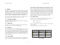
Table 1 Frame formats and sizes for the STOC/-C. .................................. 11
Table 2 Submodes for the STOC YUV format. ........................................ 12
Table 3 Bus bandwidth requirements at different frame rates................... 13
Table 4 Horizontal and vertical field of view for different lenses.............. 18
Table 5 Submodes invoked by settings in smallv...................................... 21
Table 6 Frame rates for the STOC............................................................. 23
3
©2005 VIDERE DESIGN
STOC USER’S MANUAL
1.1
1 Introduction
Characteristics of stereo system
• On-device stereo processing
Xilinx Spartan 3 – 1000 processor, 88 MHz
512 KB SRAM
The STOC is a new type of device. It functions as a complete vision
processor, combining stereo cameras and an embedded processor to
produce 3D stereo information. The processor was developed at SRI
International’s Artificial Intelligence Lab, for use in real-time vision and
robotics projects. Because the embedded processor has been designed for
just this task, it is more capable than the fastest PC, achieving over 40 Gops
(40 billion operations per second). And it does this at a fraction of the
power – just 0.8 watts for the processor, and 2.4 watts for the whole device.
The result is an output stream of 3D information, at a resolution of
640x480, at 30 frames per second.
• Stereo Processing
640x480, 64 disparities @ 30 Hz
Subpixel interpolation of disparity to 1/16 pixel
15x15 correlation window
9x9 Laplacian of Gaussian preprocessing kernel
Post-processing uniqueness check
9 cm baseline
• Fully calibrated for lens distortion at the factory
Recalibration in the field for change of lenses
The stereo cameras are 640x480 (VGA), progressive scan CMOS imagers
mounted in a rigid body. They have a global shutter – all pixels are
exposed at exactly the same time. This makes the STOC suitable for
environments with fast movement, such as on an outdoor vehicle. The
imagers have excellent dynamic range, sensitivity, anti-blooming, and noise
characteristics. They are fully controllable: the user can set exposure, gain,
decimation, etc.
• Firmware upgrades via IEEE1394 connection
• Power: 0.84 W for stereo processing, 2.4 W total
1.2
Characteristics of imagers
• Micron MT9V022 CMOS imagers
Global shutter
Simultaneous exposure and readout – true 30 fps
640x480 maximum image size
1/3” format
High sensitivity, low noise
Low pixel cross-talk
The STOC uses standard miniature lenses, or standard CS-mount lenses, for
user-changeable optics. Wide-angle to telephoto options are available,
depending on the application. The device comes fully calibrated, ready to
produce 3D information out of the box. A simple, in-field calibration
procedure is available if the lenses are changed.
The STOC has an IEEE 1394 (FireWire) interface for output and power. It
connects to any 6-pin FW port, and delivers real-time 3D information using
the DCAM 1.30 standard.
• Fully synchronized stereo – left and right pixels are
interleaved in the video stream
SRI’s Small Vision System (SVS) software has an interface to the STOC,
and is included with each stereo head. The SVS software includes software
drivers for the STOC for MS Windows 98SE/ME/2000/XP, and for Linux
2.4.and 2.6 kernels.
• Monochrome or Bayer Color
• High frame rates – 30 Hz for 640x480
• Extensive control of video parameters
Automatic or manual control of exposure and gain
4
©2005 VIDERE DESIGN
STOC USER’S MANUAL
Automatic control of black level
Manual control of color balance
• 50 Hz mode – reduces indoor light interference in
countries with 50 Hz electrical line frequency
1.3
General
• Stereo calibration information stored on the device
• IEEE 1394 interface to standard PC hardware
Carries power and commands to device, data to PC
DCAM 1.30 compatible
• Miniature 12mm diameter or CS-mount lenses,
interchangeable |Standard focal lengths 2.1,3.6, and 6.5
mm]
• Anodized aluminum alloy chassis, high rigidity
5
©2005 VIDERE DESIGN
STOC USER’S MANUAL
1.4
rectifiedimages). There is no need to perform any calibration steps – the
STOC is ready to start producing range results out of the box. However,
you may want to change the lenses at some point, and the device can easily
be recalibrated in the field, just like other Videre stereo devices.
Stereo analysis
The STOC board runs an optimized version of the SRI Small Vision
System (SVS) stereo algorithms. This version produces the same results as
SVS running on a standard PC, but is implemented inside the stereo device
on a small reconfigurable processor, called a Field Programmable Gate
Array (FPGA). The use of the FPGA frees up the host PC from the
expensive stereo calculations, and makes it available for all of the user’s
application code.
More information about the stereo processing algorithm can be found in the
technical pages for SVS, at www.ai.sri.com/~konolige/svs.
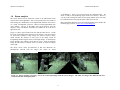
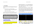
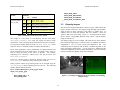
Figure 1-1 shows typical results from SVS and the STOC device. On the
left is one of the input images from the stereo cameras. The stereo images
are processed to produce a range image, also called a disparity image,
which encodes the distance to each pixel in the image, based on
triangulating matched regions in the left and right images. In the disparity
image, brighter areas indicate pixels that are closer. From the disparity
image, the 3D structure of objects can be re-created, as in the two images
on the right.
The STOC device comes pre-calibrated, so that lens distortions are
automatically removed from the images (the results are called
Figure 1-1 Stages in STOC processing. Left is one of the input images from the stereo imagers. The other two images show different 3D views
reconstructed from the disparity data.
6
©2005 VIDERE DESIGN
STOC USER’S MANUAL
1.5
Global Shutter
The STOC has a global shutter. Almost all other CMOS imagers have a
rolling shutter. With rolling shutter, each row of pixels is exposed just
before it is read out. So each row is exposed at a different time from other
rows. This leads to motion blur – a skewing of moving objects from top to
bottom.
Global shutter, on the other hand, exposes every pixel at the same time.
The charge on exposed pixels is then transferred to a set of storage bins,
and read out to give an image. Because the pixels are exposed at the same
time, there is no motion blur. With its high sensitivity, the STOC allows
for very short exposure times, even under moderate lighting conditions. So
it is appropriate for high-motion applications, such as outdoor robotics,
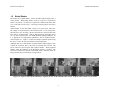
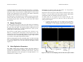
motion capture, etc. Figure 1-2 shows an example of motion capture using
the device. Notice the stop-action motion of the model plane.
Although there are a small number of global-shutter CMOS imagers, most
of them are sequential, that is, the pixels are exposed, then read out. The
pixels cannot be exposed again until readout finishes. With sequential
readout, either the framerate or the maximum exposure is limited. The
STOC has simultaneous exposure and readout, that is, while the pixels are
being exposed, the previous image is being read out.
Figure 1-2 Sequence taken by the MT9V022. Exposure 0.7 ms, 30 Hz, 640x480 video stream. Sequence shows about every 4th frame.
7
©2005 VIDERE DESIGN
STOC USER’S MANUAL
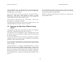
Start the SVS main program, smallv(.exe), on the host computer. You
should see a screen as in Figure 2-1. The message window should indicate
that the “DCS Digital Stereo Interface” is present. If not, go back to
software installation (Section 4.2), and follow the instructions for
configuring the correct capture library.
2 Quick Start
The STOC/-C normally comes assembled with the lenses mounted. If you
need to change the lenses, or if you are supplying your own, please see
Section 0.
Pull down the Input chooser, and select the Video option. If everything
has been set up correctly, the SVS interface will recognize and configure
the stereo head, and a success message will appear in the info text window.
The “Proc Capable” button will light up to indicate the presence of the
STOC processor, and the stereo parameter controls will be grayed out, since
the STOC has fixed parameters. If not, the Input chooser will go back to
None, and an error message will appear in the info window. Please see
Section 4 for troubleshooting.
To set up and test the STOC/-C, you will need the following:
1.
Host computer with an IEEE 1394 PCI (desktop) or PCMCIA
(laptop) card, OHCI compliant; or a built-in IEEE 1394 port.
2.
IEEE 1394 6-pin to 6-pin cable.
3.
Small Vision System installed on the host computer.
To view stereo video, press the Continuous button. By default, the
STOC device is put into its “Stereo Processing” mode, in which it sends the
Install the IEEE 1394 host card, if necessary, according to the directions in
Section 4.1. Install the Small Vision System software (see Section 4.2).
Plug one end of the IEEE 1394 6-pin video cable into the 1394 jack on the
back of the STOC/-C, and the other into an IEEE 1394 port on the host PC.
Note: The STOC draws power from the IEEE 1394 bus. PCI cards, or
built-in ports for desktop machines, normally supply this power. For
PCMCIA cards (PC Cards), and laptops with a built-in port, no power
is available. In this case, external power must be supplied – see Section
5.3.
The PC operating system will normally recognize the STOC, and install the
correct system drivers. Please see the Videre support web pages
(www.videredesign.com/support.htm) for specific information about
installation for your OS. At this point, you should check to see that the
STOC has been recognized by the system.
It takes the STOC device about 20 seconds to configure itself, as it sets up
internal calibration tables based on lens parameters. During this time, the
LED on the device will blink slowly. When it stops blinking, it should stay
lit, indicating the device is recognized by the PC. If it is not lit, then there is
a problem with the IEEE 1394 drivers on the PC.
Figure 2-1 SVS main program window.
8
©2005 VIDERE DESIGN
STOC USER’S MANUAL
left image plus the disparity (range) image. In the left window there will
be the left image from the camera; in the right image, the disparity image
produced by stereo processing. If the message “Image timed out” appears,
then there is a problem with the IEEE 1394 drivers; please see Section 4. If
the images are too light or too dark, you can change the exposure and gain
settings (Section 7.4). Images can be saved using the File menu.
The STOC device is a self-contained ranging device. It produces range
information directly on the device, without any computation on the PC.
The smallv program displays this information, as well as the original,
rectified left image.
You can view a 3D version of the disparity image by converting it into a 3D
point cloud. Choose the “3D Display” button, and an OpenGL window will
appear, with the range information converted into a point cloud. You can
navigate the viewpoint of the window by moving the mouse while holding
down the left button.
The STOC has flexible output modes. The default mode is to output the
left rectified image and the disparity range information. There are four
modes:
1.
2.
3.
4.
Left rectified image + disparity (default)
Original raw images
Rectified images
Test image
A more complete description of the video capture options is in Section 7.
The SVS interface API and sample programs are described in the SVS
User’s Manual. It is helpful to review Section 7 in conjunction with the
SVS documentation. The SVS Calibration Addendum should be consulted
if the calibration is redone – see Section 8.
9
©2005 VIDERE DESIGN
STOC USER’S MANUAL
video modes (frame size, decimation) will cause the frame rate to change,
and this will be reflected in the LED flash rate.
3 Hardware Overview
There are no user-settable switches on the STOC/-C.
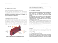
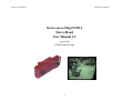
Figure 3-1 shows the hardware configuration of the STOC/-C.
3.1
The imager module has a milled aluminum alloy frame that rigidly holds
two VGA imagers, separated by a fixed distance of 9 cm. Lens mounts are
an integral part of the frame, and miniature 12 mm diameter lenses are
screwed into these holders. There is an IR cutoff filter, with a knee at
approximately 680 nm, permanently mounted inside the lens holder. See
Section 6 for appropriate lens characteristics.
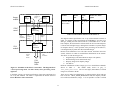
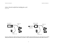
Figure 3-2 shows the design of the internal hardware of the STOC/-C. In
the stereo imager module, two CMOS imagers, each of size 640x480 pixels,
digitize incoming light into a digital stream. The imagers operate in
progressive mode only, that is, each line is output in succession from the
full frame.
The maximum video rate is 12 megapixels per second from each imager,
which produces 640x480 at 30 Hz. The imagers are synchronized to a
common clock, so that the corresponding pixels from each imager are
output at precisely the same time.
The interface module is mounted on the back of the stereo head. One IEEE
1394 port is placed at the back of the module; it is inset so that the IEEE
1394 plug does not stick out from the device.
A status LED indicates video imager activity. When the device is powered
and connected to an IEEE 1394 card on the host computer, it will flash
slowly during the initialization of the STOC board, for about 40 seconds.
At the end of this time, it will stay on if the device has been recognized by
the host PC. The LED will begin flashing again as soon as images are
being acquired by the host computer, at ½ the frame rate. Changing the
The two digital streams are fed into the STOC board. There, they are first
rectified to eliminate lens distortion and mechanical misalignment. Then,
the rectified images are processed to extract disparity (range) information at
each pixel. The disparity image and the left rectified image are interlaced,
pixel by pixel, and sent to the interface board.
On the interface board, the interlaced video stream is transferred to the
IEEE 1394 interface module, which communicates to the host PC over an
IEEE 1394 digital cable. The module also accepts commands from the host
PC over the cable, and uses these commands to control imaging modes such
as exposure.
IEEE 1394
port on back
Right
miniature
lens
Hardware Schematic
LED
indicator
The IEEE 1394 interface module can communicate at the maximum IEEE
1394 data rate, 400 MBps. Of this, the maximum data rate for video
transfer is 32 MB/s.
Left
miniature
lens
3.2
Frame Formats and Rates
The IEEE 1394 interface electronics on the STOC supports a maximum rate
of 32 megapixels per second. At this rate, there is no need for large buffer
memories to hold video data on the stereo device. The STOC/-C conforms
Figure 3-1. Physical layout of the STOC/-C stereo head.
10
©2005 VIDERE DESIGN
STOC USER’S MANUAL
Imager
module
Left
Imager
STOC
board
8-bit pixels
12 MHz per
imager
Format
Frame
size
Frame
rate
(default)
Frame rate, 50 Hz
option
Format 0, Mode 3
YUV 16 bits
640x480
7.5, 15, 30
Hz
6.25, 12.5 25 Hz
Right
Imager
Stereo
Processing
1394
imaging
commands
Table 1 Frame formats and sizes for the STOC/-C.
Disparity
image
Left
rectified
image
The Digital Camera Specification was set up with monocular cameras in
mind. To conform to this specification, the STH-MDS/-C uses the YUV
data type, sending one 8-bit video stream on Y, and another on UV. On the
host computer, the SVS interface software takes the YUV stream and parses
it into the left and right images, making them available as separate images
in computer memory. It also performs color processing, for the STOC-C,
converting the Bayer pattern into full-color RGB images.
1394
Interface
Electronics
1394
module
Digital
Video
Stream
Because of the limitation of two 8-bit video streams, the STOC device has
various submodes in which it sends different information on the streams.
The choice of video stream types are:
1394
commands
1.
2.
3.
4.
1394
Digital
Cable
Original image (8-bit monochrome or Bayer color pattern)
Rectified image (8-bit monochrome only)
Disparity image (8-bit disparity image)
Test Pattern
Figure 3-2 Schematic of the STOC/-C electronics. The diagram shows
a stereo processing mode. In other modes, stereo processing can be
bypassed.
Different combinations of these images give rise to the different submodes
The default mode, shown in gray, is
shown in Table 2.
PROC_MODE_RECTIFIED. The left and right (monochrome) rectified
images are sent back to the PC.
to the IIDC version 1.30 camera specification. Frame rates and frame sizes
are set by this standard. The STOC/-C implements the formats shown in
Error! Reference source not found..
There are two modes in which disparity is computed on the STOC and sent
back to the PC. PROC_MODE_DISPARITY sends the disparity and the
left rectified (monochrome) image. It is not possible to send a rectified
11
©2005 VIDERE DESIGN
STOC USER’S MANUAL
Format
PROC_MODE_TEST,
PROC_MODE_RECTIFIED,
PROC_MODE_DISPARITY,
PROC_MODE_DISPARITY_RAW
};
Submode
Format 0, Mode 3
YUV 16 bits
Y
UV
NAME
LO
RO
PROC_MODE_OFF,
PROC_MODE_NONE
LR
RR
PROC_MODE_RECTIFIED
3.3
LR
D
PROC_MODE_DISPARITY
LO
D
PROC_MODE_DISPARITY_RAW
TP
TP
PROC_MODE_TEST
The STOC processing board produces a disparity image, which encodes the
range to objects in the scene. The disparity image has high value (brighter)
when an object is closer, and lower value when it is further away. In
addition, there are filters that eliminate bad stereo matches – these will
appear as dark areas in the image. Figure 3-3 An image from the STOC
device, and the corresponding disparity image. shows a typical disparity
image from the device.
Table 2 Submodes for the STOC YUV format.
color image in 8 bits; hence, to send disparity and the color image,
PROC_MODE_DISPARITY_RAW sends the original left Bayer image
(unrectified). Color processing and rectification then takes place on the PC.
Disparity images
The disparity image is 10 bits in depth. The search area for stereo matches
between left and right images is 64 pixels (6 bits). In addition, the match is
interpolated to 1/16 of a pixel, giving and additional 4 bits. The
relationship between disparity and 3D XYZ coordinates depends on the
lenses and imager characteristics – see the SVS Users’ Manual and the
Calibration Addendum for more technical information. There are functions
in SVS to translate the disparity image into XYZ points.
To send just the original images to the PC, use PROC_MODE_OFF. In this
mode, the STOC/-C functions just like an ordinary STH-DCSG/-C.
In the smallv application, various combinations of requested features will
put the STOC into one of the modes above. In general, smallv will try to
keep as much processing on the STOC as possible. For example,
requesting Stereo and Warp, without color, will put the STOC into
PROC_MODE_DISPARITY.
If the Proc Capable button is turned off, then the STOC will revert to
PROC_MODE_OFF, and all processing will take place on the PC.
Under program control, the processing mode can be changed using the
svsVideoImages object controlling the stereo device. The following
member function will set the mode.
bool SetProcMode(proc_mode_type mode);
enum proc_mode_type
{
PROC_MODE_OFF = 0,
PROC_MODE_NONE,
Figure 3-3 An image from the STOC device, and the corresponding
disparity image.
12
©2005 VIDERE DESIGN
STOC USER’S MANUAL
In sending video information over the IEEE 1394 bus, the STOC device
uses 16 bits/pixel: 8 bits/pixel for the left image, and 8 bits/pixel for the
disparity image (default mode). Thus, the disparity image must be
compressed. For the first implementation of the STOC, the lower two bits
are truncated. Future implementations will use companding (lower values
are preserved, higher values are compressed) and 24 bit/pixel IEEE 1394
modes.
3.4
capture images at the same time.
Each IEEE 1394 PC Card or PCI Card defines a separate IEEE 1394 bus.
The two or three ports on the card all belong to the same bus, as does any
IEEE 1394 hub connected to these ports. Separate PC Cards and PCI Cards
cannot be connected to each other.
The number of devices that can simultaneously send video is determined by
the maximum bandwidth of the bus for isochronous transfers: 32 MB/s.
This rate cannot be exceeded by the combined video streams on the bus.
50 Hz Operation
Table 3 shows the bandwidth requirements for the STOC in various modes
and for various frame rates. Using this table, it is possible to determine the
maximum number devices that can stream video simultaneously. For
example, at 15 Hz and 640x480 resolution, a maximum of 3 STOC devices
can send video information at the same time.
Indoor lighting, especially from fluorescent fixtures, can oscillate at the
frequency of the electrical supply. If the image frame rate does not divide
evenly into this frequency, there can be moving horizontal bands of
alternating light and dark moving in the output.
For countries with 60 Hz power such as the United State, the frame rates in
the third column of Error! Reference source not found. are ideal. In
many other countries, the electrical line frequency is 50 Hz. For these
countries, there is a mode to change the frame rates of the STOC to submultiples of 50 Hz. These frame rates are shown in the last column of
Error! Reference source not found..
The bus bandwidth consumed by a device is more than would be expected
from just counting the number of bytes in each frame, because there are
blank cycles on the bus, when no data is being transmitted, even though the
bandwidth is reserved. Thus, it makes no difference whether the rate is 30
Hz or 25 Hz, the bus bandwidth consumed is the same.
The frame rate mode of the STOC device can be changed by using the
Firmware Parameter dialog – see Section 7.7.
3.5
Multiple Devices
Multiple STOC devices can be attached to the same IEEE 1394 bus. When
streaming video at the same frame rate, they are synchronized, so that they
Frame
size
Bus MB per
frame stereo
30 / 25
Hz
15 / 12.5
Hz
7.5 / 6.25
Hz
3.75 /
3.125 Hz
640x480
0.683 MB
20.5 MB
10.2 MB
5.12 MB
N/A
320x240
0.171
5.12 MB
2.56 MB
1.28 MB
N/A
Table 3 Bus bandwidth requirements at different frame rates.
13
©2005 VIDERE DESIGN
STOC USER’S MANUAL
through installation steps for the low-level drivers. You may need your MS
Windows OS CD to install some files.
4 Installing the 1394 Host Card and Capture
Software
The STOC must be powered from the IEEE 1394 bus. Desktop PCs supply
power to the bus; laptops do not. See Section 5 for information about
cabling and power for the IEEE 1394 bus.
The STOC/-C connects to a host computer via a digital 1394 interface. The
host PC must have a 1394 port, and software to interface to the video
stream from the camera. This interface software presents the video stream
from the 1394 hardware as a set of stereo frames to the user program (see
Figure 4-1). The STOC/-C comes with interface software for either MS
Windows 98SE/ME/2000/XP or Linux.
4.1
4.1.2 Linux Hardware and Driver Installation
Linux kernels 2.4 or 2.6 kernels are required for operation. Please see the
Videre Design website (www.videredesign.com/support.htm) for current
information. GCC 3.x is recommended as the compiler; there is a separate
SVS distribution for GCC 2.95.x, but it is not as reliable.
1394 Hardware and Drivers
4.2
Before installing the software interface, the PC must be equipped with a
1394 port. If there is one already present, a built-in port, then you can skip
this section. Otherwise you have to install a PCI or PCMCIA card. The
card must be OHCI compliant, which all current cards are.
The STOC/-C comes with the SVS stereo software, and several sample
applications, including the GUI application described in this manual.
For the most up-to-date information about installation, please see the Videre
Design website (www.videredesign.com/support.htm).
4.1.1 MS Windows Hardware Installation
To install the software under MS Windows, execute the file svsXXX.exe.
If you have installed a previous version of SVS, the installation wizard will
ask you if you want to un-install the old version. It is best to uninstall the
old version, then start the installation file again and install the new one.
For the most up-to-date information about installation, please see the Videre
Design website (www.videredesign.com/support.htm).
MS Windows 98SE, ME, 2000, or XP is required.
The installation process will add the relevant interface and application
software.
For a PCI card, insert the card into a free PCI slot with the computer power
off, and start the computer. With a PCMCIA card, insert it into the
PCMCIA slot. In either case, the New Hardware wizard will walk you
1394
video
stream
1394
PC
Hardware
Low-level
1394
driver
STH-MD1
interface
software
STOC Software
To install the software under Linux, untar the file svsXXX.tgz in a new
directory, which will become the top-level directory of the software. You
should also set the environment variable SVSDIR to this directory, and add
bin/ to your LD_LIBRARY_PATH variable.
To
user
program
libsvscap.so and svsgrab.lib/dll are the capture libraries for
Linux and MS Windows, respectively. By default, these libraries are set up
during installation to the correct ones for the STOC. Should there be any
problem, you can re-copy STOC libraries into the library files.
Figure 4-1 Host PC low-level software structure.
14
©2005 VIDERE DESIGN
STOC USER’S MANUAL
In MSW Windows, execute the file bin\setup_dcs.bat. This will
copy svsdcs.dll/lib as the interface libraries.
only way to run the SVS calibration procedures is through the
smallvcal(.exe) application.
Under Linux, copy the following file in the bin/ directory:
smallv(.exe) is a GUI-based application that allows the user to
exercise the capture and stereo functions of the STOC/-C. It is described in
earlier sections of this document.
dcscap.so -> libsvscap.so
(Linux)
You can check that the correct interface library is installed, by looking at
the information text when the capture application is started. It should say
“DCS digital stereo interface”. If not, the wrong interface library is
installed in svsgrab.dll or libsvscap.so.
smallvmat(.exe) is similar to smallv, with the addition of a MatLab
interface for sending images and stereo information to MatLab. You must
have installed the R13 release of MatLab to run this program. There is also
a version of SVS that can be invoked directly from MatLab – again, see the
SVS User’s Manual.
The directory structure for the software is:
smallvcal(.exe) is the same as smallv, with the addition of a
calibration package for calibrating a stereo rig. Use this application to
perform calibration on your stereo system.
bin/
smallv(.exe)
smallvcal(.exe)
smallvmat(.exe)
stcap(.exe) is a simple application that connects to the stereo head and
displays images. It can serve as a template for user programs that integrate
stereo capture from the STOC/-C.
svsgrab.dll/lib
libsvscap.so
interface libraries
stereo calculation libraries
src/
flwin.cpp
image_io.cpp
svsclass.h
svs.h
flwin.h
samples/
smallv.cpp
fldispx.cpp
*.dsw, *.dsp, makefile
stdisp(.exe) is a simple application that connects to the stereo head,
grabs images and performs stereo analysis, and displays the results. It can
serve as a template for user programs that integrate stereo capture and
computation from the STOC/-C.
There are several applications – see the SVS User’s Manual for more
information. The source code for all applications is included in the
distribution. The stereo calculation libraries are also included, so that user
applications can link to them. The calibration libraries are not included; the
15
©2005 VIDERE DESIGN
STOC USER’S MANUAL
capability of supplying power, and come with an adapter for supplying
power to the 1394 cable through a wall transformer.
5 IEEE 1394 Interface
Any 1394 card is suitable, as long as it conforms to OHCI (open host
controller interface) specifications. All current cards do, but some older
cards may not.
Digital image information is transferred from the STOC/-C to the host PC
via a 1394 cable. The cable sends a video stream from the imagers to the
PC, and sends commands from the PC to the stereo head to control
exposure, subsampling, etc. The cable also supplies power to the stereo
head.
5.1
5.3
Power to the STOC is supplied through the IEEE 1394 cable. The IEEE
1394 system must supply this power, about 2.4 Watt.
IEEE 1394 Cable
There are two typical PC systems: desktops and laptops.
The STOC/-C must be connected to the host PC via a 6-pin male-male
IEEE 1394 cable. The maximum length for such a cable is 4.5 m (about 15
feet). The cable supplies both signals and power to the stereo head. The
port on the STOC is recessed, so that the IEEE 1394 cable plug will not
stick out from the camera.
• Desktop PCs have either a built-in IEEE 1394 port, or a PCI card with
IEEE 1394 ports. In both cases, the desktop should supplysufficient
power to run the STOC.
• Laptop PCs have either a built-in IEEE 1394 port, or a plug-in PC Card
(sometimes called a PCMCIA card) with several IEEE 1394 ports. In
both cases, the laptop does not supply power to the IEEE 1394 bus,
and a source of external power must be used – see below.
The distance between the stereo head and the PC can be extended by using
a 1394 repeater.
Several 1394-enabled devices can be connected together, as long as the
connection topology doesn’t have any loops. The STOC/-C can be
connected at any point in such a topology. At a maximum, it will need
about 60% of the bandwidth of a 400 MBps connection.
5.2
Supplying Power
External power to the IEEE 1394 bus must have the following
characteristics:
7 to 16 VDC, > 3 W
The IEEE 1394 spec allows up to 40 VDC on the bus, but in practice many
devices such as PC Cards will fail if a voltage higher than 16 VDC or so is
used. We recommend using a 12 VDC source.
IEEE 1394 Host Interface
The host computer must have an available 1394 port. Some portables and
desktops come with built-in ports. If these are 6-pin ports, they can be
connected directly to the STOC/-C. Sony laptops also support an
alternative 4-pin 1394 cabling, which has the signal pins but no power.
There are adapters that convert from 4-pin to 6-pin styles; these adapters
use an external power supply transformer.
Power can be supplied to the bus through an IEEE 1394 hub or PC Card
with an external port. Most hubs have such a port; most PC Cards do not.
The PC Card supplied by Videre has a power port.
The format of the power plug can vary with the hub or PC Card, so please
check the specifications for the device. Generally, the positive terminal of
the plug is on the inside, and the negative is the outside cylinder.
If the host PC doesn’t have a built-in 1394 port, one can be added by
installing a 1394 PCI card or PCMCIA card for laptops. 1394 PCI cards
have 6-pin ports, and supply power. PCMCIA cards do not have the
16
©2005 VIDERE DESIGN
STOC USER’S MANUAL
Figure 5-1 shows the two configurations for supplying power. A wall
transformer converts line voltage to 12 VDC, and is plugged into a hub or
the PC Card.
PC Card with
power port
IEEE 1394 hub
with power port
IEEE 1394
Cable
IEEE 1394
Cable
IEEE 1394
Cable to PC
Power –
12 VDC, >3W
Power –
12 VDC, >3W
Figure 5-1 External power supply connections. On the left is power supplied to a PC Card with a power port. On the right, power is supplied
through a hub with a power port. Power should be 7 to 16 VDC, at > 1.5 W. Check the PC Card or hub for the type of power connector.
17
©2005 VIDERE DESIGN
STOC USER’S MANUAL
The STOC/-C uses either 12mm diameter miniature lenses, or CS-mount
locking lenses. Miniature lenses are screwed into integral lens-holders
milled into the aluminum chassis. The lenses are focused at the factory, and
firmly glued into place. There are no adjustments to be performed on the
lenses. It is possible to change both types of lenses, although changing the
miniature lenses is not recommended; see Section 6.7 and 6.8 below.
The focal length is a primary determinant of the performance of a stereo
system. It affects two important aspects of the stereo system: how wide a
field of view the system can see, and how good the range resolution of the
stereo is. Unfortunately there’s a tradeoff here. A wide-angle lens (short
focal length) gives a great field of view, but causes a drop in range
resolution. A telephoto lens (long focal length) can only see a small field of
view, but gives better range resolution. So the choice of lens focal length
usually involves a compromise. In typical situations, one usually chooses
the focal length based on the narrowest field of view acceptable for an
application, and then takes whatever range resolution comes with it.
Lenses are characterized optically by imager size, F number, and focal
length. Following subsections discuss the choice of these values.
6.5
6.1
The field of view is completely determined by the focal length.
formulas for the FOV in horizontal and vertical directions are:
6 Lenses
Cleaning the Imagers
VFOV = 2 arctan(1.44 / f )
Imager Size
where f is in millimeters. For example, a 2.8 mm lens yields a horizontal
FOV of 87 degrees.
The imager size is the largest size of imager that can be covered by the lens.
The STOC imager is 1/3” size (about 6mm in diameter).
6.3
Table 4 shows the FOV for some standard focal lengths.
F Number
The F number is a measure of the light-gathering ability of a lens. The
lower the F number, the better it is at pulling in light, and the better the
STOC will see in low-illumination settings. For indoor work, an F number
of 1.8 is acceptable, and 1.4 is even better. For outdoors, higher F numbers
are fine. Miniature lenses do not have any iris control; instead, they rely on
electronic exposure and gain control to automatically compensate for
different light conditions.
6.4
The
HFOV = 2 arctan(1.92 / f )
It should not be necessary to clean the imagers, since they are sealed off by
an IR filter inside the lens mount.
6.2
Field of View
Focal Length
Lens focal length
Horizontal FOV
Vertical FOV
2.1 mm
85 deg
69 deg
3.6
56
44
5.7
37
27
8.0
27
20
Table 4 Horizontal and vertical field of view for different
lens focal lengths.
The focal length is the distance from the lens virtual viewpoint to the
imager. It defines how large an angle the imager views through the lens.
18
©2005 VIDERE DESIGN
STOC USER’S MANUAL
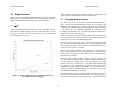
6.6
Table 4 plots this relationship for several focal lengths. At any distance, the
range resolution is inversely proportional to the focal length.
Range Resolution
Range resolution is the minimum distance the stereo system can distinguish.
Since stereo is a triangulation operation, the range resolution gets worse
with increasing distance from the stereo head. The relationship is:
6.7
Changing Miniature Lenses
The STOC comes with 12 mm diameter miniature lenses glued firmly in
place. We do not recommend changing the lenses, but it is possible to do.
If the lenses are changed or in any way moved, then the device will lose its
calibration, and a calibration must be performed and the results downloaded
to the device (see the Calibration Addendum for information about
performing the calibration step). Section 8 has information about how to
download a calibration file to the STOC.
r2
Δr =
Δd ,
bf
where b is the baseline between the imagers, f is the focal length of the lens,
and Δd is the smallest disparity the stereo system can detect. For the
STOC/-C, b is 90 mm, and Δd is 0.375 um (pixel size of 6.0 um, divided
by the interpolation factor of 16).
While the lenses have been glued into their holders, the hold of the glue can
be broken, and the lenses removed. Doing so may damage the lenses, and
for this reason we do not recommend changing them.
To remove the lenses, use a pliers with a soft tissue around the top of the
lens, to prevent scratching from the plier jaws. Grab the lens head firmly
with the pliers, and rotate counter-clockwise. The lens should rotate in its
socket, but it takes some force to do this.
Once the lens has been removed, use pressurized air to clean out the lens
holder. Then install the new lens, which should have a 12 mm diameter
barrel, with a screw pitch of 0.5 mm. Install the lens as described below,
and check for a good focus.
The screw mates with the lens holder opening. To insert a lens, place its
back end on the lens holder opening as straight as possible, and slowly turn
it counter-clockwise (looking down at the lens), applying some slight
pressure, until you feel a small “click”. This indicates that the threads are
in a position to engage. Without removing pressure, rotate clockwise until
the threads of the lens engage the lens holder. If you encounter a lot of
resistance, you may be cross-threading the lens. Forcing it on at this point
will damage the lens holder or lens threads.
Once the threads are engaged, continue screwing it on until some portion of
the thread on the lens barrel is in the lens holder. Then, plug in the device,
and start video streaming (in Original Image mode). Screw the lens down
Figure 6-1 Range resolution in mm as a function of distance, for
several different lens focal lengths.
19
©2005 VIDERE DESIGN
STOC USER’S MANUAL
while watching the video. You should be able to get a good, sharp image.
Screwing down too much past the point of good focus can damage the
internal IR filter, so be careful here.
Once the threads are engaged, continue screwing it on until it seats firmly.
You can snug it down, but do not tighten it excessively, since this can
damage the lens and the lens holder threads.
Once you have found a good focus, unscrew the lens until its barrel is
almost out.
Then apply a small amount of Lok-Tite or similar
threadlocking compound. These compounds come in several strengths; use
a light-strength one if you intend to remove the lens.
Normal care should be used in taking care of the lenses, as with lenses for
any good-quality camera.
Screw the lens in again until you get a sharp image.
threadlocker set, usually about 10 minutes.
Then, let the
Once both lenses are installed, you will need to re-calibrate the device, and
upload the calibration to the STOC. Please see Section 8
6.8
Replacing and Adjusting CS-Mount Locking
Lenses
Any adjustment or replacement of CS-mount lenses on the STOC should be
followed by re-calibration of the STOC device (Section 8).
CS-mount lenses come with thumbscrew locks for holding the focus and
iris settings. They are set at the factory, usually with the iris wide open and
the focus set to infinity.
If you need to adjust the focus or iris, then it is a good idea to re-calibrate
Adjusting the focus or iris usually results in changing the internal camera
parameters, and the calibration will suffer.
It is easy to replace CS-mount lenses. To remove the lens, unscrew the lens
counter-clockwise. There will be some initial resistance, and then it should
unscrew smoothly.
CS-mount lenses have a 1” diameter, 28 threads-per-inch screw on their
back end. The screw mates with the lens holder opening. To insert a lens,
place its back end on the lens holder opening as straight as possible, and
gently turn it clockwise (looking down at the lens) until it engages the
threads of the lens holder. If you encounter a lot of resistance, you may be
cross-threading the lens. Forcing it on will damage the lens holder or lens
threads.
20
©2005 VIDERE DESIGN
STOC USER’S MANUAL
inputs. The default submode, left rectified image and disparity image, is set
by using Function->Stereo and turning Warp on. By default, this is done
when the STOC is first opened. Setting Function->None turns off stereo
processing, and outputs the right rectified image in place of the disparity
image. Turning off Warp will output both original images. Table 5
summarizes these settings. Note that it is not possible to invoke the Test
Submode from smallv.
7 User Controls
The CMOS imagers are fully controllable via the 1394 interface. User
programs may input color images (STOC-C only), set video digitization
parameters (exposure, gain, red and blue balance), and subsampling modes.
All of these parameters can be set with the SRI Small Vision System. They
are also accessible to user programs through the capture API (Section 8).
7.2
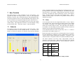
User controls for frame size and sampling modes are on the main capture
window dialog. Video digitization controls are accessed through a dialog
invoked with the Video… menu item. Figure 7-1 shows the dialog.
7.1
Color
Color information from the stereo digital head (STOC-C only) is input as
raw colorized pixels, and converted by the interface library into an RGB
color channel. The primary color channel corresponds to the left image,
which is the reference image for stereo. The right image color channel is
not available. The color images will be de-warped to take into account lens
distortion, and are aligned with the disparity image.
Submode
The submode specifies what video streams are output by the STOC. There
is an API call in SVS to set the submode directly – see the SVS Users’
Manual. In smallv, the submode is set indirectly, by the Function and Warp
Color information from the camera is input only if the Color button is
pressed on the main window (Figure 2-1).
Because the typical color camera uses a colorizing filter on top of its pixels,
the color information is sampled at a lower resolution than a similar noncolorized camera samples monochrome information. In general, a color
camera has about ¼ the spatial resolution of a similar monochrome camera.
The relative amounts of the three colors, red/green/blue, affects the
appearance of the color image. Many color CCD imagers have attached
processors that automatically balance the offsets among these colors, to
Figure 7-1 Video Parameters dialog.
Functio
n
War
p
Submode
None
Off
LO, RO
None
On
LR, RR
Stereo
On
LR, DP
Stereo
Off
Not
available
Table 5 Submodes invoked by settings in smallv.
21
©2005 VIDERE DESIGN
STOC USER’S MANUAL
produce an image that is overall neutral (called white balance). The STOCC provides manual color balance by allowing variable gain on the red and
blue pixels, relative to the green pixels. Manual balance is useful in many
machine vision applications, because automatic white balance continuously
changes the relative amount of color in the image.
Both imagers are treated in exactly the same manner. It is not possible to
set a different exposure or gain on each imager.
Digitization control can operate in either manual or automatic mode. Refer
to Figure 7-1 for the controls in the video capture program. Both manual
and automatic modes are available for the STOC(-C) devices.
The manual gain on red and blue pixels is adjusted using the Red and Blue
controls on the Video Parameters dialog. For a particular lighting source,
try adjusting the gains until a white area in the scene looks white, without
any color bias.
In manual mode, the user program sets the exposure and gain. The
exposure and gain are based on a 0 to 100 scale. Here are some tips for
setting exposure and gain.
•
7.3
Gamma Correction
To display properly for human viewing, most video images are formatted to
have a nonlinear relationship between the intensity of light at a pixel and
the value of the video signal. The nonlinear function compensates for loss
of definition in low light areas. Typically the function is xγ, where γ is 0.45,
and the signal is called “gamma corrected.”
In general, keep the gain as low as possible, since it introduces
additional noise into the system. Use it only if the exposure is set
to maximum, or if the exposure must be kept low to minimize
The STOC has on-chip gamma correction that can be turned on or off.
When on, it compresses the 10-bit output of each pixel into 8 bits. The
compression occurs mostly in the higher light levels. With on-chip gamma
correction, the STOC can handle larger dynamic ranges of light, such as
occur outdoors with bright sunlight and deep shadow.
Without on-chip gamma correction, the display looks very dark in low-light
areas. You can add gamma correction to the displayed image by choosing
an appropriate gamma value in the slider under the right display window
(Figure 7-2).
7.4
Video Digitization Parameters
The CMOS imagers have electronic exposure and gain controls to
compensate for varying lighting conditions. The exposure can vary from a
maximum of a full frame time to a minimum of one line time. Gain is an
additional amplification of the video signal, for low-light situations. It is
settable from 0 to 12 dB (1x to 4x).
Frame size
Sampling mode
Gamma
correction
Figure 7-2 Frame size and sampling controls in the main capture window.
22
©2005 VIDERE DESIGN
STOC USER’S MANUAL
• 50 Hz operation
motion blur. Indoors, the gain is usually set higher because of the
lower light levels.
•
This parameter can be changed by using the Firmware Parameter dialog,
which is only available from the smallvcal menubar. Choosing this
menu brings up the dialog, which is shown in Figure 7-3.
Adjust the manual iris of the lens to as small an opening as
possible for your application, without having to use gain. This
will increase the depth of field and give better optical performance.
Indoors, the iris usually is fully open. Outdoors, in bright
conditions, the iris can be partially closed.
The dialog lists many of the internal parameters of the device, which are
fixed in the firmware. The one changeable parameter is for 50 Hz or 60 Hz
operation (Section 3.3).
There are automatic modes for both exposure and gain. In auto mode, gain
and exposure are controlled by the imager, which samples the incoming
image and sends changes the exposure and gain parameters. The auto
algorithm will try to reduce gain as much as possible, while still
maintaining overall light levels in the image.
The Firmware Parameter dialog is only available after the STOC has been
opened by pulling down the Video item of the Input chooser. To use 50
Hz operation, check the box, and then press the Save button. This choice
is downloaded and stored in the device, and will cause 50 Hz operation
every time the STOC is accessed. To change back to 60 Hz, uncheck the
box and again save it to the device.
Auto mode for gain and exposure can be set separately. For the STOC, if
there is relatively slow motion, it is recommended to use a manual mode for
gain, and auto mode for exposure. Indoors, set the gain to a higher value;
outdoors, set it to a low value. With exposure in auto mode, the light on the
image will be adjusted by changing the exposure.
It is also possible to clear any calibration parameters that are saved on the
STOC firmware. If the calibration parameters are present, the Clear
Calibration button will be activated. Pressing this button will clear the
parameters. See the SVS Users’ Manual for information on saving and
loading calibration parameters on the device.
For high-speed motion, it is better to set the exposure to a fixed, low value,
and then use auto-gain to keep reasonable light levels on the imager.
7.5
Subsampling
The STOC device does not perform subsampling operations. All images
are transmitted at a resolution of 640x480.
7.6
Frame Rates
Frame rates from the STOC/-C depend on the frame size. Table 6 shows the
frame rates available for each of the frame sizes. Note that a 50 Hz option
is available – see Section 3.3
7.7
Resolution
Frame
Bin on
imager
Bin on
PC
Frames per Second
640 x 480
Full
no
no
7.5, 15, 30
Firmware Parameters
There is one firmware parameter that affects the overall behavior of the
STOC.
Table 6 Frame rates for the STOC.
23
©2005 VIDERE DESIGN
STOC USER’S MANUAL
Figure 7-3 Firmware parameters dialog.
24
©2005 VIDERE DESIGN
STOC USER’S MANUAL
Firmware dialog. A file chooser dialog will appear, allowing you
to select the FPGA configuration file. The chooser should be at
the bin/ directory; if it is not, navigate to this directory. Then
choose one of the following files:
8 Redoing Calibration
Whenever the lenses are changed, or the focus or iris is adjusted, it is
recommended to perform a re-calibration of the STOC device. This
requires the following steps:
1.
Do not use any other Firewire devices during re-configuration,
including Firewire external disk drives.
2.
Erase the current calibration. The current calibration is stored on
the device. It can be erased using the bin/smallvcal
program. Plug in the device, start the program, and open the
device (choose Video from the Input pulldown). Once the
device is opened, the Firmware menu item will become available.
Click on this item to open the firmware dialog. Click on the
Clear Cal button.
3.
For the target, a square size of 100 mm or larger is
recommended for a good calibration.
c.
After calibrating, save the calibration to a file for backup.
Then send it to the main program, using the Send button.
4.
At this point, you should have a valid calibration, and it should be
loaded into the main smallvcal window, either by using the
Send button from the calibration dialog, or by loading it from a
file using the File->Load Parameters menu item. In the
Firmware dialog, choose Upload Cal to save the calibration to
the device.
5.
Once the calibration is uploaded to the device, the FPGA can be
re-configured.
Choose the Config STOC button in the
[monochrome system]
b.
do_sys_color.dat
[color system]
The Debug window will show the progress of the configuration.
First the FPGA program will be downloaded and verified, then the
rectification information for the left and right images. At the end,
there will be a message indicating successful configuration.
Make sure to use un-rectified images as input. The
Warp button should be off.
b.
do_sys.dat
Configuration will now take place, and will require about 15
minutes. During this time, do not use the Firewire system for
other tasks. It is ok to run other programs, as long as they do not
access the Firewire bus. If anything interrupts the configuration,
you can start over from step 4.
Exit the smallvcal program. Now perform a calibration, using
the guidelines in the Calibration Addendum. Some things to note:
a.
a.
6.
Quit the smallvcal program, unplug the STOC device, and
plug it back in. It should go through its normal startup procedure,
with the light blinking for about 20 seconds.
7.
Start smallv and verify the operation of the device.
If there are any problems with re-configuration, or if the device does not
work properly after re-configuration, please contact Videre Design.
25
©2005 VIDERE DESIGN
STOC USER’S MANUAL
9 Interface Software API
Please see the Small Vision System manual for information about the
software API for capturing and saving images.
26
©2005 VIDERE DESIGN
STOC USER’S MANUAL
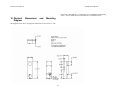
larger hole is threaded for a ¼-20 machine screw (standard tripod mounting
screw). The two smaller holes are threaded for 6-32 machine screws.
10 Physical
Diagram
Dimensions
and
Mounting
The diagram below shows the physical dimensions for the STOC/-C. The
27
©2005 VIDERE DESIGN
STOC USER’S MANUAL
Exposure
1 line time to full frame
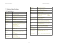
11 Technical Specifications
Gain
0 – 12 dB (1x – 4x)
11.1 Specifications
Sensitivity
4.8 V/lux-sec (monochrome)
STOC processor
S/N
> 60 dB, no gain
Power
Imagers and FW interface: 1.45 W
STOC board:
0.84 W
Total:
2.29 W
Synchronization
Internal: pixel-locked
External: 60 us
Lens
3.6 mm miniature lenses standard
Other lenses optional (2.1 to 16 mm)
Size
1.725” high x 5.2” long x 1.55” deep
(excluding lenses)
Weight
190 g (6.7 oz), without lenses
71 g (2.5 oz) for 4.0 mm lenses
Stereo Baseline
9 cm
SVS software
Linux kernel 2.4, 2.6
MSW 98SE, ME, 2000 and XP
Environmental
0-40o C, < 90% humidity (noncondensing)
Processor
performance
Number of
disparities
Correlation window
size
Laplacian of
Gaussian kernel
Xilinx Spartan 3 - 1000
35 Gops at 84 MHz
64 pixels; 1/16 pixel interpolation
15x15 pixels
9x9 pixels
Post-filtering
Texture and uniqueness check
Imagers
1/3” format CMOS (Micron MT9V022)
640x480 active area
Global shutter
Progressive scan
Color or monochrome
Digital Camera
Specification
Version 1.30
Format
640x480
8 bit monochrome or Bayer color
pattern
10 bit disparity
Frame Rates
7.5, 15, 30 Hz
6.5, 12.5, 25 Hz
Max 30 Hz at 640x480
28
©2005 VIDERE DESIGN
STOC USER’S MANUAL
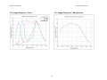
11.2 Imager Response - Color
11.3 Imager Response – Monochrome
29
©2005 VIDERE DESIGN
STOC USER’S MANUAL
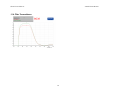
11.4 Filter Transmittance
30
©2005 VIDERE DESIGN
STOC USER’S MANUAL
12 Technical Support
For technical support, please contact Videre Design by email or FAX.
Videre Design
865 College Avenue
Menlo Park, CA 94025
Fax: (650)323-3646
Email: [email protected]
Technical information about stereo algorithms and stereo calibration can be
found at www.ai.sri.com/~konolige/svs.
31