1
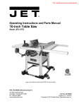
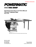
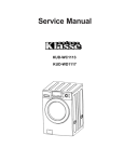
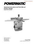
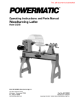
1.
Shift extension wing so it is slightly above saw
table surface.
2.
Begin by tightening the three screws (17mm
wrench) under the extension wing that secure
it to saw table. Tighten these just enough to
hold wing in place but loose enough to change
wing height by tapping on it.
For instructions on mounting the accessory wood
extension table, consult Accu-Fence manual,
document no. M-2195075Z.
Lay straight edge (Figure 6) across saw table
and extension wing, extending it out past edge
of wing as shown.
Refer to Figure 8.
3.
4.
5.
7.9 Wood Extension Table
7.10 Motor cover
At the motor side, slide hinge pins through motor
cover cylinders and into hinge barrels on saw.
Close motor cover until it catches on latch post on
saw.
Move straight edge to several places along
wing, as you continue to nudge wing level with
saw table. As each area of wing becomes
flush with table, tighten the screw under that
area. Continue until all three screws are fully
tightened. NOTE: Make sure front edge of
wing remains flush with front edge of saw
table.
Note: The catch mechanism may require slight
adjustment to ensure proper alignment.
Repeat above steps for opposite extension
wing.
7.7 Rails and Fence
With extension wings properly aligned, the rails
and Accu-Fence® assembly can now be mounted
to saw. Consult manual no. M-2195075Z, that
accompanies the fence.
NOTE: The switch bracket must be mounted to
front rail before installing guide tube. Follow
instructions in section 7.8, then install guide tube.
7.8 Switch bracket
Refer to Figure 7.
Figure 8
After front rail has been installed, mount switch
bracket with three flat head screws (HP-7).
Mount guide tube to front rail, referring to
instructions in your Accu-Fence manual.
7.11 Table insert
Refer to Figure 9.
Push insert down into table opening. Verify that
insert lies flush with table surface by resting a
straight edge across it at various points. If insert is
not flush along its length, turn any of six set screws
to raise or lower that area of the insert.
Figure 7
12