1
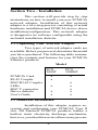
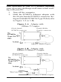
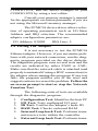
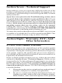
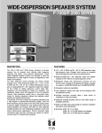
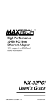
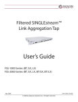
High Performance
Ethernet PCMCIA
Adapters
PCN2000 Series
User's Guide
Part #MAN004 Rev. 1.1
REPAIR INFORMATION FORM
Please take a moment to note the following information. Include this form in the unlikely event that
you need to return the product for warranty service.
Refer to Section Eight for complete Warranty
information and procedures on returning your
product.
Product: _________________________
Serial Number: ____________________
Purchase Date: ____________________
Purchased From: __________________
Your Name: ______________________
Address: _________________________
City, State, Zip: ___________________
Day-time Phone #: _________________
Company Name: ___________________
Complete the following information ONLY
after you have been assisted by a Technical
Support Representative:
RMA Number: ____________________
Problem Description: _______________
_________________________________
_________________________________
_________________________________
_________________________________
_________________________________
___________________________________
_______________________________________
_________________________________________
Contents
Section One
Section Two
Section Three
Section Four
Section Five
Section Six
Section Seven
Section Eight
Introduction ............................ 1
Installation .............................. 2
Network Driver Installation .. 7
Troubleshooting ...................... 7
Cable Information .................. 9
Specifications ........................ 10
Technical Support ................ 11
Warranty, FCC And Other
Information ........................... 11
Section One - Introduction
Maxtech's PCN2000 Series PCMCIA network adapters are high performance, credit-card
sized Ethernet network adapters. The adapter plugs
into a PCMCIA Type II (or higher) slot providing
a 16-bit bus interface and a 16 KB network data
packet buffer. The adapter also features low-powerconsumption design and is software configurable.
The adapter complies with the Personal Computer
Memory Card Industry Association (PCMCIA)
Release 2.1 Type II standard and also with the
IEEE 802.3 standards for Ethernet.
Minimum hardware requirements are an
IBM AT (or better) fully compatible PC with 512K
RAM running DOS 3.3 or higher, equipped with
a PCMCIA Release 2.1 Type II slot.
1
Section Two - Installation
This section will provide step by step
instructions on how to install your new PCMCIA
network adapter. Installation of this network
adapter is a two-step process consisting of actual
hardware installation and PCMCIA device driver
installation/configuration. This network adapter
is designed to be software configurable using the
included installation diskette.
2.1 Unpacking Your Network Adapter
Two types of network adapter cards are
available. Before you proceed, determine the model
you have purchased. The following table summarizes the contents and features for your PCMCIA
Ethernet products:
Model
PCN
2000T
PCN
2000BT
x
x
x
PCMCIA Card
RJ-45 Coupler
BNC/RJ-45 Coupler
LEDs
BNC T-connector
Driver diskette
User's Guide
x
x
x
x
x
x
x
x
2.2 Hardware Installation
Installation of this adapter requires accessing and configuring your PCMCIA Type II
slot. All Maxtech PCMCIA products feature a
built-in static electricity discharge mechanism,
however, you should exercise all necessary precau-
2
tions described in your PC's manual regarding
static electricity discharge at all times when working with your PC.
1.
2.
Turn off the computer
Hold the PCMCIA Ethernet adapter with
the 68-pin female PCMCIA connector facing an available PCMCIA Type II slot (refer
to Figure 1-A or 1-B).
Figure 1-A Adapter with
10Base-T Coupler
68-pin female
PCMCIA connector
Female Media
Coupler connector
To
PCMCIA
Type 2.0
Slot
To Hub
10Base-T Media Coupler
Figure 1-B Adapter with
10Base-2/10Base-T Coupler
68-pin female
PCMCIA connector
Female Media
Coupler connector
To
PCMCIA
Type 2.0
Slot
To Hub
or
Thin Coax Cable
10Base-2/10Base-T Media Coupler
3
3.
4.
5.
Insert the Ethernet adapter into the PCMCIA
Type II slot. The keyed guide slots on the
PCMCIA Ethernet adapter will not allow
incorrect insertion. Insert the Ethernet
adapter gently but firmly into the slot until
it stops.
Insert the 10Base-T (or 10Base-2/10BaseT) Media Coupler into the adapter. One end
of this coupler has a special spring-action
connector which fits into the PCMCIA
Ethernet adapter. To insert or remove the
spring-action connector, squeeze the locking arms on either side of the connector.
This connector is keyed and will not allow
incorrect insertion (refer to Figure 1-A or 1B).
Attach the network cable to your Media
Coupler. Use either UTP cable for 10BaseT networks or thin coaxial cable for 10Base2 networks. Refer to Section Five for detailed cable information.
2.3 PCMCIA Device Driver Installation
Before any network driver or software is
loaded, you must first install a PCMCIA device
driver for the PCMCIA Ethernet adapter. Your
computer should already provide support for
PCMCIA products via special programs on the
utility diskette shipped with the COMPUTER
(known as Socket Service/Card Service). Execute
the Socket/Card Service programs according to
specific instructions supplied by the computer’s
manual. If your computer DOES NOT provide
support for PCMCIA products, contact your computer vendor for information on availability of
Socket/Card Services. You will now install the
PCMCIA Ethernet device driver from the supplied
4
driver diskette. Consult the README file on the
driver diskette for specific instructions on how to
install the driver.
Note: If you are unable to obtain Socket
Service and Card Service from your computer
manufacturer, you may still be able to use the
PCMCIA Ethernet adapter with the included
PCMCIA device driver. Consult the README
file to determine if your computer is supported in
this configuration and for instructions on how to
proceed.
The PCMCIA Ethernet adapter uses the
memory region D400-D7FF to read Ethernet ID
and other information from on-board flash ROM.
Please be certain that this memory region is excluded from usage by other programs, including
memory managers. Memory management is a
component of Microsoft DOS and Windows and is
used extensively. If you are running a Microsoft
memory manager, make sure that the x=D400D7FF
parameter
appears
in
the
Device=EMM386.EXE entry in your
CONFIG.SYS.
Example:
DEVICE=EMM386.EXE NOEMS X=D400-D7FF
Since Socket Service and Card Service
generally require 4-8 KB of contiguous space in
the Upper Memory Blocks, we recommend using
the following entry:
Example:
DEVICE=EMM386.EXE NOEMS X=D000-DFFF
If
you
do
DEVICE=EMM386.EXE
5
not
have
a
entry in your
CONFIG.SYS, add the above example to your
CONFIG.SYS by using a text editor.
Consult your memory manager's manual
for the appropriate exclusion parameter if you are
not using the Microsoft memory manager.
The PCMCIA device driver allows selection of operating parameters such as I/O Base
Address and IRQ selection. The recommended
adapter configuration parameters are:
I/O Address: 0300H
IRQ Line: 5
2.4 Testing The Adapter
It is not necessary to test the PCMCIA
Ethernet adapter. However, if you encounter problems with your network connection, run the diagnostic program provided on the driver diskette.
The diagnostic program runs several tests and the
results are indicated by either PASS or FAIL.
Make sure that the network cable is attached (and
properly terminated if using a BNC connection) to
the adapter when running this program. If any test
fails, the program notifies you of the error and
suggests actions to correct the problem. Follow the
on-screen prompt to start or stop the Network
Function Test.
The following suite of tests are available
through the diagnostic program:
1.
2.
3.
4.
5.
6.
Configuration Test: Identifies the host PC
I/O Test: Tests configured I/O port
ID Test: Verifies the adapter’s node ID
RAM Test: Checks on-board RAM
Internal Loop back Test: Performs transmit/receive tests within the controller
External Loop back Test: Performs trans-
6
7.
8.
mit/receive tests on the network link
Interrupt Test: Checks Interrupt Line
Network Function: Performs network
packet transmit/receive tests
Section Three - Network Driver
Installation
The supplied network drivers allow the
Ethernet adapter to work with various network
operating systems (i.e., Novell Netware, Microsoft
LAN Manager, etc.). Drivers for most popular
network operating systems are included in the
driver diskette in separate subdirectories. Each
directory also includes a README.TXT file describing the driver. Refer to the RELEASE.TXT
file on the driver diskette for more information on
the available drivers.
Note: Consult the README file in the
ROOT directory of the driver diskette for additional information on installation of these network drivers for your particular network operating system.
Section Four - Troubleshooting
This section describes some of the common problems you may encounter while using
your network adapter. When troubleshooting, you
should make sure that the network you are connected to is functioning. If you suspect that the
adapter is malfunctioning, replace it with another
adapter which is known to function properly. Also
try the adapter in another computer. This can
indicate whether the adapter or computer causes
the problem. If you can not resolve your difficulty
7
after reading the following information, contact
your dealer or vendor for assistance.
Most adapter failure after installation is
caused by: A) Incorrectly installed PCMCIA driver,
B)Not excluding memory address D400-D7FF
when using a memory manager, C)I/O base address and IRQ Line conflict, or D)Cable problems.
4.1 Incorrectly Installed PCMCIA Driver
The included PCMCIA driver runs as a
Card Service Client and should only be loaded
after the Socket and Card Services are loaded. Be
certain that the CONFIG.SYS file contains DEVICE= entries in this order.
4.2 Not Excluding Memory Address D400D7FF
The PCMCIA Ethernet adapter uses the
memory region D400-D7FF to read Ethernet ID
and other information from on-board flash ROM.
This memory region must be excluded from
usage by other programs, including memory
managers. If you are running Microsoft's memory
manager, make sure that the x=D400-D7FF or
x=D000-DFFF parameter appears in the
Device=EMM386.EXE entry in your
CONFIG.SYS. Refer to Section 2.3 for detailed
information.
4.3 I/O Base Address and IRQ Conflict
Make sure that the I/O address and IRQ
used by the adapter is not already in use by
another device in your PC. If your PC has built-in
serial ports then you will not be able to use IRQ 4
(COM1) or IRQ 3 (COM2). Other adapters in your
8
system may already use addresses 0300H or 0320H
(example: sound/audio card). Vary the settings on
your network adapter by running the PCMCIA
device driver with different I/O port addresses and
IRQs to eliminate the conflict. Running the diagnostic program will also help to detect configuration conflicts.
4.4 Cable Problems
A) Observe the green Link Status LED if
you are using a 10Base-T network. Turn on the
computer. Connect the network cable and observe
the green LINK LED. If the LED is ON, then the
system is connected. Otherwise check for a proper
RJ-45 connection.
B) Make sure the coaxial cable is properly terminated if you are using a 10Base-2
network. Each end of a coaxial segment must be
properly terminated with a 50-ohm terminator.
You may use a simple ohm meter to determine if
the cable is functioning properly. Disconnect all
nodes on the network and measure the resistance
of the terminators. If the terminators do not measure 50 ohms +/- 1%, replace the terminator.
Measure the coaxial cable with a 50-ohm terminator attached to one end. The total resistance of the
cable plus the terminator should be no more than
a few ohms more than the terminator alone.
Section Five - Cable Information
The Maxtech PCN2000 Series PCMCIA
Ethernet adapters support both popular cable
schemes used in Ethernet networks:
PCN2000T
Supports 10Base-T network.
9
PCN2000BT
Supports both 10Base-2 and
10Base-T networks.
10Base-T networks use unshielded
twisted-pair cable and 8-pin RJ-45 modular connectors. Use only 22-26 AWG 2-pair 100 ohm/ft.
UTP with two to three twists per foot. The cable
must use solid copper conductors and UL codes
CM, CMR, and CMP are required. The computer
on the network is connected via a star topology (i.e.
each node is connected to a HUB, not to each
other). Maximum cable length is 300' (100 m).
10Base-2 networks use a single conductor coaxial cable and BNC connectors. Use only
RG-58A/U or RG-58C/U coaxial cables. Each
network node is connected to the coaxial cable via
a T-connector (included). The minimum distance
between T-connectors is 1.6' (0.5m). The T-connector must be plugged directly into the network
adapter (no cable is allowed between the T-connector and the adapter). No more than 30 connections are allowed per segment and the maximum
segment length is 607' (185 m). The cable must be
terminated at each end by 50-ohm terminators.
Section Six - Specifications
Network Standard:
Interface:
Bus Width:
RAM Buffer:
I/O address:
IRQ line:
Media Coupler:
Power:
Temperature:
Dimensions:
Certification:
IEEE 802.3
PCMCIA Release 2.1 TYPE II
16-bit
16KB
240, 260, 300, 320, 340, 360
3, 4, 5, 10, 11, 12, 15
10Base-T or 10Base-2 & 10Base-T
0.16A @ 5V (10BaseT)
0.28A @ 5V (10Base2)
0 to 55 degrees C (Operating); -20 to 80
degrees C (Non-operating)
85mm x 54mm x 5mm
FCC Part 15 Class A
10
Section Seven - Technical Support
In the unlikely event you experience difficulty in the use of the
product, or if it does not operate as described, we suggest you: (1)
consult the Troubleshooting section of this guide and (2) consult
with your dealer.
If you have not referred to the Troubleshooting section, there
is a good chance the solution to your problem is there. If you
still can not solve the problem, call the Service Center at (201)
579-2954 between 9:00 a.m. and 5:30 p.m. (EST Monday through
Friday). If the nature of your question is related to the network
operating system that you are using, refer to its manual.
Calling the Service Center without complete and accurate
information concerning the NATURE OF THE PROBLEM
will be both time-consuming and frustrating for you.
You may also reach us through our electronic BBS. Any revisions
or updates of available drivers will be posted on the BBS. This
service is available 24 hours a day at: (201) 579-2380
Section Eight - Warranty, FCC, And
Other Information
8.1 Five Year Limited Warranty
Maxtech warrants to the original buyer of this product against
defects in material and workmanship for five years from the date
of purchase. During the warranty period, Maxtech will repair (or
at its option, replace) the product that proves to be defective,
provided the product has not been abused, misused, modified, or
repaired by an unauthorized center.
In the event the product requires service, follow the procedure
outlined in Section Seven - Technical Support. When you are
instructed by the Technical Support Representative to return the
product for repair, you will be given an RMA (Return Merchandise Authorization) number. You must have an RMA Number to
return the product for service. Use the following procedure to
return the product:
1.
2.
Return the product in its original package and packing (if
possible), and put it in a sturdy corrugated box.
Be sure to complete the Repair Information Form, including your name, address, day-time telephone number,
RMA number, and a brief description of the problem
11
(also enclose a check for out-of-warranty repair). Enclose your check or Postal Money Order for $7.50 to
cover the cost of return shipping/handling. Please do not
send cash or stamps. RMA received without the $7.50 fee
will not be processed.
4.
After wrapping the package securely for shipping, print
your name, return address and the RMA # clearly on the
outside of your package.
5.
Ship the unit prepaid via UPS or the U.S. Postal Service
to the address supplied by the technician when you call.
We recommend that the unit be insured.
This warranty is valid for products sold in North America only.
Contact your local authorized distributor or dealer for the warranty offered in other areas.
All warranty services must be performed by Authorized Service
Centers. There are no user serviceable parts inside the unit. Do not
remove any components or attempt to service the unit by any
unauthorized service center. This warranty is voided if the product
has been abused, misused, modified, or repaired by an unauthorized service center.
8.2 FCC Compliance
This device complies with Part 15 of the FCC Rules. Operation is
subject to the following two conditions: (1) this device may not
cause harmful interference, and (2) this device must accept any
interference received, including interference that may cause undesirable operation.
8.3 Disclaimer, Copyright, And Other Notices
The information contained in this manual has been validated at the
time of this manual's production. The manufacturer reserves the
right to make any changes and improvements in the product
described in this manual at any time and without notice. Consequently the manufacturer assumes no liability for damages incurred directly or indirectly from errors, omissions or discrepancies between the product and the manual.
All registered trademarks are the property of their respective
owners. Copyright © 1994 Maxtech. All rights reserved. No
reproduction of this document in any form is allowed without
written permission from Maxtech.
First Edition
GZ/DR - Version 1.1
12