1
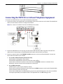
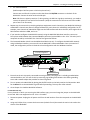
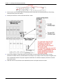
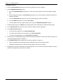
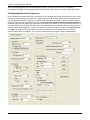
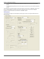
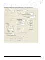
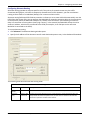
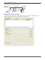
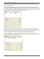
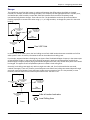
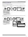
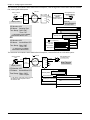
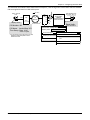
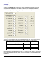
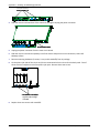
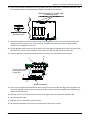
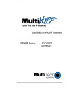
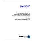
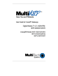
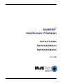
 Appendix C – Installing an MVP428
Upgrade Card
This appendix describes how to install an additional circuit board into the MVP410, changing it from a 4‐channel VOIP to an 8‐channel VOIP. Procedure Overview (A) Attach four standoffs to main circuit card. (B) Mate the 60‐pin connectors (male connector on main circuit card; female on upgrade card). (C) Attach upgrade card to main circuit card (4 screws). *
*
(A)
Replace main card screws
with standoffs here
(2 places).
Add standoffs here (2 places).
*
(C)
Attach upgrade card
(screws into standoffs
-- 4 places).
(B)
Mate 60-pin
connectors.
Installing the Card 1.
Power down and unplug the MVP410 unit. 2.
Using a Phillips driver, remove the blank cover plate at the rear of the MVP410 chassis. Save the screws. screws on blank cover plate (2)
3.
Using a Phillips driver, remove the three screws that secure the main circuit board and back panel assembly to the chassis. Important: Follow standard ESD precautions to protect the circuit board from static electricity damage. MultiVOIP® Voice/Fax over IP Gateways 145