1
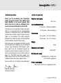
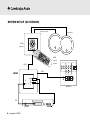
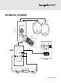
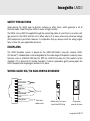
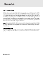
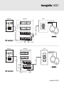
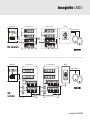
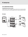
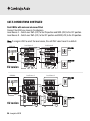
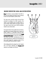
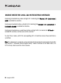
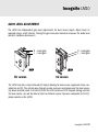
LM10
Local Input Module
Installation Guide
CONTENTS
Introduction......................................................3
Specifications...................................................3
System Set-up ..................................................4
Mounting the LM10..........................................6
Fitting the LM10...............................................6
Safety precautions...........................................7
Faceplates........................................................7
Wiring guide......................................................7
Cat-5 connections............................................8
Single local audio source set-up............................9
Dual LM10s fitted in a single zone.......................11
Single LM10 with main and sub-zone fitted..12-13
Dual LM10s with main and sub-zones fitted.......14
Source rotate for local 1 & 2...............................
on the keypad.................................................15
Audio level adjustment..................................17
Limited warranty.............................................18
2 Incognito LM10
Incognito LM10
INTRODUCTION
SPECIFICATION
Thank you for purchasing this Cambridge
Audio Incognito product. The LM10 Local
Input Module is an in-wall module that
allows the user to add an additional local
source to those distributed by the AH10.
Max line level inputs
The local source may only be heard in the room
where it is connected and the corresponding
sub-zone (if connected) and is not distributed
to other rooms. LM10s can be fitted in as many
rooms as are desired. The LM10 connects
between the audio hub and a KP10 amplified
control module using Cat-5/5e wiring.
Each main zone can support two LM10s, giving
you the option of listening to one or two local
sources (eg. Playstation, MP3 player). Each
local source can be controlled through the
Incognito remote and/or keypad (see instructions on entering local source rotate mode on
page 15). The LM10 can also support subzones (where fitted) so that the local source is
audible in both main and subzone areas.
Now we invite you to sit back, relax and enjoy !
2.2 V rms
Cat-5 connection type
EU Version - Krone punchdown
CU Version - 110 punchdown
Dimensions
EU Version - 50 x 50 x 48mm
CU Version - 44 x 70 x 54mm
Weight
100g
Maximum cable length
30M/100ft
IR (Infra-red output)
Modulated 34–40 kHz and
55–59 kHz supported
Power requirement
24V DC @ 20 mA max (supplied by hub)
Matthew Bramble
Technical Director
Incognito LM10 3
SYSTEM SET-UP (EU VERSION)
Speaker cable
Speakers
KP10
Keypad
LR10
remote
control
CAT-5
CAT-5
LM10
L
IR
R
AH10 Hub
IR1
4 Incognito LM10
Incognito LM10
SYSTEM SET-UP (CU VERSION)
Speaker cable
Speakers
KP10
Keypad
LR10
remote control
CAT-5
CAT-5
LM10
L
IR
R
AH10 Hub
IR1
Incognito LM10 5
MOUNTING THE LM10
Locate the LM10 near the local source. Check all connections and test the system’s operation
before installing the LM10 into the wall. Using the included hardware, install the LM10 into a
standard electricians back-box (pattress) (LM10-EU=UK47mm depth single gang, LM10-CU=USAtype J-box 50mm).
Important
Care should be taken in choosing a site for the LM10, ALWAYS refer to the precautions later in
this guide. Bear in mind that any local sources will likely require mains power.
The LM10 must never be installed in a back-box (pattress) which also contains mains wiring.
The recommended maximum length for use with standard Cat-5 cable is 30m from hub to LM10
to keypad in total. Screened Cat-5 can also be used.
FITTING THE LM10
Note: The LM10 is powered via the Cat-5 cable and no mains connection is required.
The procedure for fitting is as follows:
Remove the supplied faceplate from the LM10 by gently prising apart. It will ‘pop’ off.
Connect each wire in the Cat-5 cable to its respective terminal in the punch-down connector on
the back of the LM10.
Be very careful to follow the colour-code that is indicated on the connector. Always double-check
your connections, and your punching.
Fit the LM10 to the back-box (pattress) that you have fitted in your wall. This is done with the two
supplied screws (LM10-EU=M 3.5mm x 20, LM10-CU=6 x 32 pitch UNC x 6mm Countersunk).
Gently push the faceplate back on to the module.
6 Incognito LM10
Incognito LM10
SAFETY PRECAUTIONS
Avoid placing the LM10 near to dimmer switches or other items, which generate a lot of
electrical noise. Avoid fitting the LM10 in areas of high humidity.
The LM10 runs on 24V DC supplied through the connecting cable. As such there is no mains voltage present in the LM10 and the unit is often safe to fit in areas where only extra low voltage
(ELV) equipment is permitted. However, it is imperative that you always check the wiring regulations in force for your application and area.
FACEPLATES
The LM10 faceplate system is based on the (LM10-EU=50x50 ‘easy-clip’ module, LM10CU=DecoraTM) standard and is interchangeable for the wide range of faceplates made by manufacturers such as (LM10-EU=MK Electric, RPP etc, LM10-CU=Leviton etc) that conform to this
standard. If it is desired to fit another faceplate, it can be replaced by gently prising apart the
LM10 faceplate and snapping on another in its place.
WIRING GUIDE: EIA/TIA 568A WIRING STANDARD
brown
white/brown
orange
white/blue
blue
white/orange
green
white/green
View from
contact end
Gather pairs, trim and
insert into RJ45 plug
Crimp wires
securely in place
Incognito LM10 7
CAT-5 CONNECTIONS
A Cat-5 cable is used to connect the LM10 to a keypad output on an AH10 hub and to a KP10
amplified control module. Use Cat-5 cables (use EIA/TIA 568A RJ-45 wire configuration, see page
7) to connect from the hub to a LM10 wall plate (optional), and then wire from the wall plate to
the KP10 (see opposite diagrams). The LM10 has punchdown connectors for the eight individual
conductors of the Cat-5 cable, use a punchdown tool (LM10-EU=Krone, LM10-CU=110+ blade)
to insert conductors. If using shielded Cat-5 cable, connect the shields to the green terminal
blocks as shown in the opposite diagrams (dotted lines).
Note: When wiring directly to the LM10, crimp on a male RJ-45 connector using the EIA/TIA 568A
RJ-45 wire configuration (see Wiring Guide: EIA/TIA 568A wiring standard on page 7) for connection to the hub.
Single local audio source
Connect the LM10 as shown in the diagrams. Switch over SW1 (LC1) to the ON position and SW2
(LC2) to the OFF position. The LM10 will respond to the Local 1 remote command when selected.
8 Incognito LM10
Incognito LM10
AH10 Hub
KP10
LM10 Rear
Speaker Cable
OUT
IN
CAT-5
CAT-5
OUT
MAIN ZONE
IN
EU version
SW1
AH10 Hub
SW2
LM10 Rear
KP10
Speaker Cable
OUT
IN
CAT-5
CAT-5
OUT
SW2
SW1
IN
MAIN ZONE
CU version
Incognito LM10 9
CAT-5 CONNECTIONS CONTINUED
It is possible to add up to two LM10 units per main zone. This gives you the option to listen to
either one by selection from the keypad or LR10 remote control (Local1/Local 2). The module
needs to be told whether there are one or two LM10’s present.
Dual LM10s fitted in a single zone
Connect the LM10s as shown in the opposite diagrams.
Local Source 1 – Switch over SW1 (LC1) to the ON position and SW2 (LC2) to the OFF position.
Local Source 2 – Switch over SW1 (LC1) to the OFF position and SW2 (LC2) to the ON position.
Note: If using an LR10 to select the local source, this will ONLY select Local 1 as default.
10 Incognito LM10
Incognito LM10
Local Source 1
AH10 Hub
Local Source 2
KP10
OUT
OUT
Speaker Cable
IN
IN
CAT-5
CAT-5
OUT
OUT
CAT-5
IN
IN
EU version
SW1 SW2
SW1 SW2
AH10 Hub
MAIN ZONE
Local Source 2
Local Source 1
KP10
OUT
OUT
IN
IN
Speaker Cable
CAT-5
OUT
OUT
CAT-5
SW2
CU
version
SW1
SW2
IN
MAIN ZONE
IN
SW1
CAT-5
Incognito LM10 11
CAT-5 CONNECTIONS CONTINUED
Single LM10 with main and sub-zone fitted
Connect the LM10 as shown in the diagrams. Switch over SW1 (LC1) to the ON position and SW2
(LC2) to the OFF position. The LM10 will respond to the Local 1 remote command when selected.
EU version
AH10 Hub
SUB-ZONE
KP10
Local Source 1
Speaker Cable
OUT
CAT-5
CAT-5
IN
MAIN ZONE
KP10
OUT
Speaker Cable
CAT-5
CAT-5
IN
SW1
12 Incognito LM10
SW2
Incognito LM10
CU version
AH10 Hub
SUB-ZONE
KP10
Local Source 1
Speaker Cable
OUT
CAT-5
CAT-5
IN
MAIN ZONE
KP10
OUT
CAT-5
CAT-5
Speaker Cable
SW2
IN
SW1
Incognito LM10 13
CAT-5 CONNECTIONS CONTINUED
Dual LM10s with main and sub-zones fitted
Connect the LM10s as shown in the diagrams.
Local Source 1 – Switch over SW1 (LC1) to the ON position and SW2 (LC2) to the OFF position.
Local Source 2 – Switch over SW1 (LC1) to the OFF position and SW2 (LC2) to the ON position.
Note: If using an LR10 to select the local source, this will ONLY select Local 1 as default.
Local Source 1
AH10 Hub
Local Source 2
OUT
OUT
CAT-5
CAT-5
CAT-5
IN
IN
OUT
OUT
CAT-5
CAT-5
CAT-5
IN
IN
EU version
SW1 SW2
AH10 Hub
Local Source 2
OUT
IN
OUT
IN
IN
SW1
CU version
14 Incognito LM10
IN
CAT-5
SW2
SW2
SUB-ZONE
KP10
OUT
OUT
CAT-5
MAIN ZONE
KP10
SW1 SW2
Local Source 1
CAT-5
SUB-ZONE
KP10
SW1
CAT-5
CAT-5
CAT-5
MAIN ZONE
KP10
Incognito LM10
SOURCE ROTATE FOR LOCAL 1&2 ON THE KEYPAD
Note: This feature is only available if the KP10 is
part of a full Incognito multi-room system with one
or two Local Input Modules (LM10) fitted.
2
3
4
5
The local source selection mode will need to be
activated to configure the KP10 correctly. This
mode is only available when the Mode Switch is
set to “AH10” mode. LM10s can only be used in
this mode. Please refer to your LM10 Installation
Guide for more information.
Pressing the Select left or right buttons on the keypad allows you to rotate through all six sources as
default. However, it is possible to allow the addition of one or two local sources by accessing Local
source selection mode. To enter this mode press
the Volume up button simultaneously with the
Power button for four seconds; the LED display will
then scroll through the sequence shown in the
illustration right and described as follows:
After holding both buttons down for a short period,
LED 2 will light indicating that Sources 1–6
(default) are available for selection.
Incognito LM10 15
SOURCE ROTATE FOR LOCAL 1&2 ON THE KEYPAD CONTINUED
Continuing to hold both keys down will light LED 3 indicating that Sources 1–6 + Local source 1
mode is available for selection.
Continuing to hold both buttons will light LED 4 indicating that Sources 1–6 + Local source 1 +
Local source 2 mode is available for selection.
Continuing to hold Volume up and Power buttons will light LED 5, to indicate that Off mode is
available for selection, and no source will be selected.
To select these modes, wait till the corresponding LED is lit and then release Power and Volume
up buttons.
Note: If no adjustment is made the system will automatically go back to volume adjustment after
two seconds. If “Standard A-BUS/Incognito Ready” mode is selected on the Mode switch, the
KP10 will only rotate round the main 6 sources.
16 Incognito LM10
Incognito LM10
AUDIO LEVEL ADJUSTMENT
The LM10 has independent gain level adjustments for local source inputs. Adjust levels as
required using a small trimmer. Turning the gain level pots clockwise increases the audio level
and anti -clockwise decreases it.
R – Local gain
L – Local gain
R – Local gain
L – Local gain
LM10
EU version
LM10
CU version
The LM10 also has a local infra-red (IR) output allowing for local source equipment to be controlled via an IR1. This will only pass through remote source or commands once the local source
has been selected (Local 1 or Local 2) from the LR10 remote or KP10 keypad. Having selected
the local source, you will be able to listen to whatever source has been connected to the R/L
phono sockets on the LM10.
Incognito LM10 17
LIMITED WARRANTY
Cambridge Audio warrants this product to be free from defects in materials and workmanship (subject to the terms
set forth below). Cambridge Audio will repair or replace (at Cambridge Audio’s option) this product or any defective
parts in this product. Warranty periods may vary from country to country. If in doubt consult your dealer and ensure
that you retain proof of purchase.
To obtain warranty service, please contact the Cambridge Audio authorised dealer from which you purchased this
product. If your dealer is not equipped to perform the repair of your Cambridge Audio product, it can be returned by
your dealer to Cambridge Audio or an authorised Cambridge Audio service agent. You will need to ship this product in
either its original packaging or packaging affording an equal degree of protection.
Proof of purchase in the form of a bill of sale or receipted invoice, which is evidence that this product is within the
warranty period, must be presented to obtain warranty service.
This warranty is invalid if (a) the factory-applied serial number has been altered or removed from this product or (b)
this product was not purchased from a Cambridge Audio authorised dealer. You may call Cambridge Audio or your
local country Cambridge Audio distributor to confirm that you have an unaltered serial number and/or you purchased
from a Cambridge Audio authorised dealer.
This warranty does not cover cosmetic damage or damage due to acts of God, accident, misuse, abuse, negligence, commercial use, or modification of, or to any part of, the product. This warranty does not cover damage due to improper
operation, maintenance or installation, or attempted repair by anyone other than Cambridge Audio or a Cambridge
Audio dealer, or authorised service agent which is authorised to do Cambridge Audio warranty work. Any unauthorised
repairs will void this warranty. This warranty does not cover products sold AS IS or WITH ALL FAULTS.
REPAIRS OR REPLACEMENTS AS PROVIDED UNDER THIS WARRANTY ARE THE EXCLUSIVE REMEDY OF THE CONSUMER. CAMBRIDGE AUDIO SHALL NOT BE LIABLE FOR ANY INCIDENTAL OR CONSEQUENTIAL DAMAGES FOR
BREACH OF ANY EXPRESS OR IMPLIED WARRANTY IN THIS PRODUCT. EXCEPT TO THE EXTENT PROHIBITED BY LAW,
THIS WARRANTY IS EXCLUSIVE AND IN LIEU OF ALL OTHER EXPRESS AND IMPLIED WARRANTIES WHATSOEVER
INCLUDING, BUT NOT LIMITED TO, THE WARRANTY OF MERCHANTABILITY AND FITNESS FOR A PRACTICAL PURPOSE.
Some countries and US states do not allow the exclusion or limitation of incidental or consequential damages or
implied warranties so the above exclusions may not apply to you. This warranty gives you specific legal rights, and you
may have other statutory rights, which vary from state to state or country to country.
18 Incognito LM10
Incognito LM10
Incognito LM10 19
Incognito LM10
www.cambridge-audio.com
Part No. AP21476/1