1
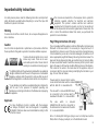
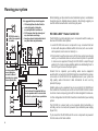
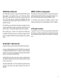
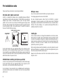
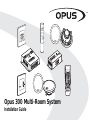
VOL
Opus 300 Multi-Room System
Installation Guide
Contents
La version française de ce manuel est disponible sur le site:
Important safety instructions........................................................................3
Eine deutsche Version der Bedienungsanleitung ist verfügbar unter:
Planning your system....................................................................................6
La versión en español de este manual está disponible en:
Pre-installation notes.....................................................................................8
La versione in lingua italiana di questo manuale è disponibile sul sito:
Audio connections......................................................................................11
Een nederlandse versie van deze gebruiksaanwijzing is beschikbaar via:
Video connections.......................................................................................12
Русская версия данного руководства находится по адресу:
Source connections....................................................................................13
Sub-zones...................................................................................................14
www.opus.eu/manuals
Advanced system options...........................................................................15
Larger systems............................................................................................18
System specifications.................................................................................19
FAQs............................................................................................................22
Limited warranty..........................................................................................23
Note: All diagrams and instructions in this guide refer to the EU version
of the WCU300 keypad.
2
Important safety instructions
For safety reasons please read the following instructions and important
safety information carefully before attempting to connect the Opus 300
Multi-Room System to the mains.
Warning
To reduce the risk of fire or electric shock, do not expose this appliance to
rain or moisture.
The crossed-out wheeled bin is the European Union symbol for
indicating separate collection for electrical and electronic
equipment. This product contains electrical and electronic
equipment which should be reused, recycled or recovered and
should not be disposed of with unsorted regular waste. Please return the
unit or contact the authorised dealer from whom you purchased this
product for more information.
Plug Fitting Instructions (UK only)
Caution
Use of controls or adjustments or performance of procedures other than
those specified in this guide may result in hazardous radiation exposure.
To reduce the risk of electric shock, do not
remove any covers. There are no userserviceable parts inside. Please refer all
servicing to an authorised servicing agent.
The lightning flash with the arrowhead symbol within an equilateral
triangle is intended to alert the user to the presence of uninsulated
‘dangerous voltage’ within the product’s enclosure that may be of
sufficient magnitude to constitute a risk of electric shock to persons.
The exclamation point within an equilateral triangle is intended to
alert the user to the presence of important operating and
maintenance (servicing) instructions in the literature accompanying
the appliance.
Approvals
The Opus Multi-Room System complies with the European
Low Voltage (73/23/EEC) and Electromagnetic Compatibility
(89/336/EEC) Directives when used and installed according to this
instruction manual.
The cord supplied with this appliance is factory fitted with a 13A mains plug
fitted with a 13A fuse inside. If it is necessary to change the fuse, it is
important that a 13A one is used. If the plug needs to be changed because
it is not suitable for your socket, or becomes damaged, it should be cut off
and an appropriate plug fitted following the wiring instructions below. The
plug must then be disposed of safely, as insertion into a 13A socket is likely
to cause an electrical hazard. Should it be necessary to fit a 3-pin BS mains
plug to the power cord the wires should be fitted as shown in this diagram.
The colours of the wires in the mains lead of this appliance may not
correspond with the coloured markings identifying the terminals in your
plug. Connect them as follows:The wire which is coloured BLUE must be
connected to the terminal which is marked
with the letter ‘N’ or coloured BLACK.
The wire which is coloured BROWN must
be connected to the terminal which is
marked with the letter ‘L’ or coloured RED.
The
wire
which
is
coloured
GREEN/YELLOW must be connected to
the terminal which is marked with the letter
‘E’ or coloured GREEN.
Note - If a 13 Amp (BS 1363) type of plug is used a 13 Amp fuse must be
fitted, either in the plug or adaptor, or on the distribution board.
3
Important safety instructions continued
Read Instructions - All the safety and operating instructions should be
read before the product is operated.
Retain Instructions - The safety and operating instructions should be
retained for future reference.
Heed Warnings - All warnings on the product and the operating
instructions should be adhered to.
Follow Instructions - All operating and use instructions should be
followed.
Cleaning - Unplug all system components from the wall outlet before
cleaning any part of the system. Do not use liquid cleaners or aerosol
cleaners. Use a damp cloth for cleaning.
Attachments - Do not use attachments which are not recommended by
Opus Technologies as they may cause hazards.
Water and Moisture - Do not use this product near water - for example,
near a bath tub, wash bowl or kitchen sink; in a wet basement, or near a
swimming pool etc.
Wall or Ceiling Mounting - Speakers should be mounted to a wall or
ceiling only as recommended by the manufacturer. Installers should also
ensure that all building regulations are strictly adhered to as cutting a hole
for a loudspeaker may affect the fire rating of a ceiling or wall.
Accessories - Do not place this product on an unstable surface, stand,
bracket or table. The product may fall, causing serious injury to
child or adult, and serious damage to the product. Use only a
surface, stand bracket or table recommended by the
manufacturer, or sold with the product. Any mounting of the product
should follow the manufacturer's instructions, and should use a mounting
accessory recommended by the manufacturer. A product and stand
combination should be moved with care. Quick stops, excessive force,
and uneven surfaces may cause the combination to overturn.
4
Ventilation - Slots and openings in the cabinets/enclosures are provided
for ventilation and to ensure reliable operation of the product and to protect
them from overheating. These openings must not be blocked or covered.
The openings should never be blocked by placing the product on a soft
surface. The MCU should not be placed in a built-in installation such as a
bookcase or rack unless proper ventilation is provided and the
manufacturer's instructions have been adhered to. For all components,
the manufacturers instructions on ventilation must be adhered to.
Power Sources - This product should be operated only from the type of
power source indicated on the marking label. If you are not sure of the type
of power supply to your home, consult your product dealer or local power
company. For products intended to operate from battery power or other
sources, refer to the operating instructions. This apparatus shall be
connected to a mains socket outlet with a protective earthing connection.
Grounding or Polarization - Do not defeat the safety purpose of the
polarized or grounding type plug. A polarized plug has two blades with
one wider than the other. A grounding type plug has two blades and a third
grounding prong. The wide blade or the third prong are provided for your
safety. If the provided plug does not fit into your outlet, consult an
electrician for replacement of the obsolete outlet.
Power-Cord Protection - Power supply cords should be routed so that
they are not likely to be walked on or pinched by items placed upon or
against them, paying particular attention to cords at plugs, convenience
receptacles, and the point where they exit from the product. The mains
plug is used as the disconnect device and shall remain readily operable.
Protective Attachment Plug - The product is equipped with an
attachment plug having overload protection. This is a safety feature. If
replacement of the plug is required, be sure the service technician has
used a replacement plug specified by the manufacturer that has the same
overload protection as the original plug.
Lightning - For added protection for this product during a lightning storm,
or when it is left unattended and unused for long periods of time, unplug
it from the wall outlet and disconnect the antenna or cable system. This
will prevent damage to the product due to lightning and power-line surges.
Replacement Parts - When replacement parts are required, be sure the
service technician uses replacement parts specified by the manufacturer or
have the same characteristics as the original part. Unauthorised
substitutions may result in fire, electric shock, or other hazards.
Overloading - Do not overload wall outlets, extension cords, or integral
convenience receptacles as this can result in a risk of fire or electric shock.
Safety Checks - Upon completion of any service or repairs to this product,
ask the service technician to perform safety checks to determine that the
product is in proper operating condition.
Object and Liquid Entry - Never push objects of any kind into this product
through openings as they may touch dangerous voltage points or short-out
parts that could result in a fire or electric shock. Never spill liquid of any
kind on the product.
Heat - The product should be situated away from heat sources such as
radiators, heat registers, stoves, or other products (including amplifiers)
that produce heat.
Servicing - Do not attempt to service this product yourself as opening or
removing covers may expose you to dangerous voltage or other hazards.
Refer all servicing to an authorised service agent.
Lithium Battery - This product is equipped with a lithium battery that is
NOT to be replaced by the user. CAUTION - Danger of explosion if battery
is incorrectly replaced. To be replaced only with the same or equivalent
type by qualified service personnel.
Damage Requiring Service - Unplug this product from the wall outlet and
refer servicing to qualified service personnel under the following
conditions:
a) When the power-supply cord or plug is damaged.
b) If liquid has been spilled, or objects have fallen onto the product.
c) If the product has been exposed to rain or water.
d) If the product does not operate normally by following the operating
instructions. Adjust only those controls that are covered by the
operating instructions as an improper adjustment of other controls may
result in damage and will often require extensive work by a qualified
technician to restore the product to its normal operation.
e) If the product has been dropped or damaged in any way.
f) When the product exhibits a distinct change in performance - this
indicates a need for service.
5
Planning your system
It is suggested that you locate keypads:
MCU300 location is
critical. See opposite
for details.
• 138cm height from the floor finish (to
centre of keypad) or taking into
account light switch locations etc
• 25-35cm away from the outer edge of
any door frame or wall edge
• Away from direct, bright sunlight which
may affect infra-red performance
When installing your Opus multi-room entertainment system, consideration
should be given to detailed advance planning. We strongly suggest you
read this entire manual before commencing any work.
MCU300 A-BUS ® Master Control Unit
The MCU300 is located alongside source components which means you
have two MCU300 location options:
1. Locate MCU300 and source components in any convenient discreet
location with adequate ventilation within the home (such as an understair cupboard, service room or cabinet), or ...
2. If it is desired to use the same sources for the Opus system as are being
used by a conventional stereo or surround sound system it is possible
to route source equipment through the MCU300 for output through
existing hi-fi or home cinema amplifiers whilst also distributing them to
the rest of your home via the Opus system.
Locate speakers in all
rooms taking into
account location of
furnishings for optimal
stereo reproduction.
Should this be required, your existing audio source equipment
would be first connected to the MCU300 and then routed from the six loop
out sockets on the MCU300 to the amplifier/receiver in your system via
high quality audio interconnect cable terminated at each end by
phono/RCA plugs.
In a bedroom it is suggested that you
locate speakers above or close to bed
location for optimal stereo reproduction.
Similarly video source equipment may be connected to the VSU300 and
then routed from the six loop out sockets on the VSU300 to the AV receiver
in a home cinema setup using phono/RCA cables designed for video use.
For this configuration the MCU300 should be located behind your existing
system.
The MCU300 is compact and can be mounted either horizontally, or
vertically, such as on a wall, and is powered by a dedicated power supply
(Opus PSU).
Try to ensure that the MCU300 and it’s source components are powered
from the same set of mains outlets.
6
VSU300 Video Switching Unit
AMR650 / OS165CC in-ceiling speakers
The VSU300 video hub works in conjunction with the MCU300 to provide
video signals to all connected zones, via 75 Ohm video cabling
(RG6/CT100 co-axial cabling can be used). Up to six video input sources
and a CCTV input may be connected and distributed, with their
corresponding audio signals routed through the MCU300 as one of its
dedicated six inputs.
When placing the ceiling-mounted speakers, thought should be given to
positions which give the best desired sound coverage throughout a room,
while not interfering with existing or planned light fittings or joists.
It is advisable to plan all aspects of installation in advance of work
beginning, preferably with the house/flat building schematics if available.
The VSU300 may be mounted either horizontally or vertically in the same
manner as the MCU300, and power is provided by the MCU300 via a Cat5e patch cable, so no extra power supply or mains socket is required.
CCTV system connection
When deciding upon a location for the MCU300 and VSU300 units
consideration should be given to space constraints, and power points for
the source equipment and MCU300, as well as integration into any existing
setups.
It is possible to connect a CCTV camera to your multi-room system. Refer
to the section on ‘Advanced system options’ for details. Please note that
extra cabling will be required in addition to that explained in the installation
notes.
WCU300 A-BUS ® Wall Control Unit
Simple and intuitive control is provided by the WCU300 A-BUS keypad.
Housed in a stylishly designed casing, the WCU300 fits into any wall and
is available with different finishes to compliment various decorative
schemes. Control of your source equipment, volume, bass, treble and other
functions can be performed by the WCU300.
Each WCU300 may be used as a main zone or sub-zone controller, with the
only difference being that the sub-zone must listen to/watch the same
source as the main zone.
Should extra amplification or an active subwoofer be required (to provide
more bass), a line level pre-amp output is provided on the back of the
WCU300.
7
Pre-installation notes
Please read these notes before commencing installation.
Wiring to zones
Run a Cat-5e cable from the MCU300 to each wall control unit.
MCU300 A-BUS Wall Control Unit
A-BUS is a standard that allows some compatibility between different
manufacturers A-BUS multi-room products. The MCU300 can be switched
between Opus A-BUS or Standard A-BUS mode. The Opus A-BUS
position is for use with our own Opus WCU300 keypad and gives extra
functions. When used with other manufacturers A-BUS keypads it should
be set to Standard A-BUS or they will not work. The switch is located on
the rear of the MCU300 (see below).
Fit a single-gang back box for each WCU300.
Run two standard speaker cables from the WCU300 to mounted
loudspeakers. If video is required, run 75 Ohm video cable (CT100/RG6
high-quality co-axial cable) from the VSU300 main zone connection either
directly to the video display, or to a wall-mounted panel fitted with a
suitable phono/RCA connector.
Audio inputs from sources
Cabling tips
Important!
OPUS A-BUS
STANDARD A-BUS
MODE SWITCH
SEE MANUAL FOR DETAILS
Cat-5e cable should be run through the installation in electrical conduit,
either metal, non-metallic, rigid or intermediate, wherever possible. Should
conduit not be available or impractical, cabling running through frames or
beams must be a minimum of 25 mm/1 inch from the nearest edge of that
structure. If the frame or beam is metallic, then the cable should be
protected by a bush or grommet.
Audio loop output
Fix to a hard surface such as a cupboard surface, not to carpet or a softlined surface, as this will inhibit airflow through the unit. Do not situate in
close proximity to any installation which will produce excessive electrical
noise such as dimmer racks etc (these may interfere with the unit). Situate
within three metres of a power socket.
VSU300 Video Switching Unit (where specified)
Locate in close proximity to the MCU300 (maximum of five metres away).
Fix to a hard surface such as a cupboard surface, not to carpet or a softlined surface, as this will inhibit airflow through the unit.
Do not situate in close proximity to any installation which will produce
excessive electrical noise such as dimmer racks etc; these may interfere
with the unit.
8
When routing cables around the installation, care must be taken to prevent
kinking and trapping. Any cable ties used must not be tightened any more
than is necessary to hold the cable in place.
Always re-check the colour code of the Cat-5e cable connections to ensure
they are correct.
WCU300 A-BUS Wall Control Unit
WCU300 EU version
Cat-5e cable
The WCU300 EU version should be fitted into a standard single UK (square)
47mm deep back-box (the stainless steel/silver WCU300 EU should be
fitted into a 50–60mm deep back-box/pattress).
The WCU300 CU version should be fitted into a standard single US J-box.
The Cat-5 cable running from the MCU300 is terminated at the 8-way
colour-coded punch down connection on the rear face of the WCU300.
Speaker cable is connected via screw terminals on the rear of the WCU300.
It is recommended the WCU300 should be positioned at a height of 138cm
from the floor finish (to centre of keypad) or taking into account light switch
locations etc.
Speaker cable
It should also be placed 25-35 cm away from the outer edge of any door
frame or wall edge.
Locate away from direct, bright sunlight which may affect infra-red
performance.
EIA/TIA 568A wiring standard
Full instructions for installing your WCU300 are supplied with the keypad.
8 7 6 5 4 3 2 1
1 2 3 4 5 6 7 8
Plug view from
contact end
View into
socket
Gather pairs,
trim and insert
into RJ45 plug
Crimp wires
securely in place
Wire colours:
1. Green/White
5. Blue/White
2. Green
6. Orange
3. Orange/White
7. Brown/White
4. Blue
8. Brown
9
Pre-installation notes continued
AMR650 / OS165CC in-ceiling speakers
Standard installation would specify AMR650/OS165CC ceiling mounted
speakers which are matched to the Opus 300 system for optimum audio
performance. However, virtually any customer-specified speaker units may
be used.
Where ceiling or wall-mounted speakers are used, care should be taken to
ensure that all building regulations are followed.
When mounting speakers flush to a ceiling or wall, ensure that enough
depth/clearance is available in the respective cavity. A clearance of at least
80mm is necessary when mounting pairs of AMR650/OS165CC speakers.
L-shaped probe used
to check available void
space before cutting
speaker holes
When deciding upon a ceiling or wall placement, care should be taken to
avoid joists, load bearing beams etc.
Before cutting ceiling loudspeaker holes it is suggested that the area is
tested for clearance by making an L - shaped probe from strong wire (eg a
coat hanger), drilling a small hole in the target area, inserting the probe and
slowly turning. Any obstructions will be immediately obvious, so that the
target area can be moved to a more suitable position.
Also, locate loudspeakers taking into account location of furnishings for
optimal stereo reproduction.
Full details of installation, connection, operation and special features can
be found in the guide that accompanies the speakers.
AMR650 / OS165CC
207mm diameter
mounting hole
10
Audio connections
PSA65U power supply to MCU300
For each MCU300 with up to four main zones connected (and no subzones) one PSA65U is required.
Connections for one MCU300 with two main zones attached:
OS165CC
OS165CC
Sub-zones require a separate PSA65U power supply.
For each MCU300 (with both main and sub-zones connected) two
PSA65U power supplies are required.
Speaker cable
Speaker cable
MCU300 to WCU300
Using a single Cat-5e cable, connect each WCU300 to the MCU300 via an
RJ45 plug using the EIA/TIA 568A wiring standard (see page 9) at the
MCU300, and an eight-way colour-coded connection at the keypad.
WCU300
The Cat-5 connection from MCU300 to WCU300 should not exceed 30 m/
100 ft.
Cat-5 cable
Sub-zones connections are made in the same way as main zone
connections but from the sub-zone sockets (see later section).
WCU300 to OS165CC or other loudspeakers
Connect the WCU300 to a pair of speakers with two runs of standard highquality speaker cable.
PSA65U
MCU300
11
Video connections
Where a VSU300 video switcher has been specified
The VSU300 is linked to the MCU300 via a Cat-5e patch cable (supplied
with the VSU300), connected to the expansion sockets on both units. This
provides power, and input switching commands direct from the system
remote control or WCU300.
Connections between MCU300 and VSU300 with two main zones and a
sub-zone attached:
OS165CC
Main video displays are connected to the VSU300 at the ‘main zone’
sockets via high quality 75 Ohm video cable (CT100/RG6 high-quality
co-axial cable) terminated at the VSU300 by a phono/RCA plug. No
external power is required by the VSU300 it is powered by the MCU300.
OS165CC
SUB-ZONE
e.g. en-suite
bathroom
MAIN ZONE
e.g. master
bedroom
Sub-zone video displays are connected in the same way, but to the four
sub-zone sockets on the VSU300.
WCU300
TV
WCU300
Cat-5
cable
TV
Cat-5
cable
Stereo/RCA
phono leads
MCU300
VSU300
CD player
DVD player
2 x PSA65U
12
Source connections
Audio source connections
Detail of audio connections between a tuner and MCU300:
Audio
Output
It is possible to connect a total of six audio source components to the
MCU300. The connections are made from a line level output on the source
equipment to one of the six inputs on the MCU300 using RCA/phono to
RCA/phono cables.
Control Bus
AM 300Ω
In
L
Out
R
Audio
source
FM 75Ω
In
Out
Audio
Output
Control Bus
Phono-Phono/RCA-RCA hi-fi interconnect cable
Video source connections
When using a VSU300 each of the six sources can also supply video.
AUDIO INPUTS FROM SOURCES
SOURCE 6
SOURCE 5
SOURCE 4
SOURCE 3
SOURCE 2
SOURCE 1
L
L
R
SOURCE 1
SOURCE 2
SOURCE 3
SOURCE 4
SOURCE 5
MCU300
R
The connections are made from a composite video output on the source
equipment to one of the six inputs on the VSU300 using good quality 75
Ohm RCA/phono to RCA/phono video cables.
SOURCE 6
AUDIO INPUTS FROM SOURCES
Remote control of source equipment through the WCU300
For remote control of the source equipment, six routed IR outputs are
provided. Individual IR emitters are plugged into the appropriate IR output
(corresponding to the respective audio input) the other end is stuck to the
IR receiving window of the source equipment:
Detail of video connections between a DVD player and VSU300:
Video Out
Front
Surround
Centre
L
Composite
Video
Coaxial
Opus IR-1
cable
S-Video
Optical
Scart Out (Composite / RGB)
Component
Cb/Pb
Cr/Pr
Video
source
Y
75 Ohm video RCA/phono cable
VIDEO INPUTS FROM SOURCES
5
6
3
VIDEO INPUTS FROM SOURCES
Audio source
1
2
MCU300
5
2
1
3
4
4
6
VSU300
13
Sub-zones
Sub-zone connections
One MCU300 hub supports four main-zones and four sub-zones (eight
rooms in total). Each sub-zone output is tied to a main zone output and
always receives the same source as its main zone (A2 sub-zone output
always receives the same source as A1, B2 always follows B1 etc).
OS165CC
Sub-zones are used for instances such as en-suite bathrooms (the
bedroom being a main zone) where it is desired to to have an area that
automatically follows the same source as another but can be independently
turned on and off, has individual bass and treble etc.
OS165CC
SUB-ZONE
e.g. en-suite
bathroom
MAIN ZONE
e.g. master
bedroom
Any main zone can have a sub-zone.
WCU300
TV
Cat-5
cable
WCU300
TV
Cat-5
cable
Stereo/RCA
phono leads
MCU300
VSU300
CD player
DVD player
2 x PSA65U
14
Advanced system options
Note: Full details of installation, connection, operation and special features
can be found in the guide that accompanies the LIM300 module.
The LIM300 Local Input Module (LIM) is an optional in-wall module that
allows the user to add additional local sources to those distributed by the
MCU300.
Speaker cable
WCU300
The local source may only be heard in the room where it is connected and
the corresponding sub-zone (if connected) and is not distributed to other
rooms. LIM300s can be fitted in as many rooms as are desired.
The LIM300 connects between the MCU300 audio hub and a WCU300
keypad using Cat-5/5e wiring. Each main zone can support two LIM300s,
giving you the option of listening to one or two local sources (eg.
Playstation, MP3 player). Each local source can be controlled through the
Opus remote and/or keypad.
Note: The MCU300 and WCU300s must be in Opus A-BUS mode in order
to use an LIM300.
OS165CC
Cat-5 cable
LRC300
LIM300
Cat-5 cable
Note: If you are running a sub-zone, this must always be wired via the
LIM300 in the same way as the main zone.
Stereo/RCA
phono
leads
MCU300
Opus IR-1 cable
Audio source
15
Advanced system options continued
AMR650 Active Speakers
The AMR650 active speakers can be used where it is not desired to have
a keypad fitted in the wall. The AMR650 active speakers feature an IR
receiver and amplifier in one of the speakers and like the WCU300 keypad
do not require mains power.
1. Using a single Cat-5e cable, connect the AMR650-A to the
MCU300/VSU300 via an RJ45 plug at the MCU300, and the eight-way
colour-coded punch down connection at the AMR650.
AMR650-A
AMR650-P
The RJ45 hub connection should be wired to EIA/TIA568A standard as
shown in the wiring guide on page 6.
The Cat-5 connection from MCU300 to the AMR650-A should not
exceed 30 m/100 ft.
2. The AMR650-A is then connected to the AMR650-P using either Cat-5e
cable terminated at eight-way colour-coded punch down connections
(all eight cores must be connected) or using a run of standard speaker
cable.
LRC300
Only one method of connection between the active and passive speaker
is necessary.
Cat-5 cable
Full details of installation, connection, operation and special features can
be found in the guide that accompanies the AMR650 speakers.
PSA65U
MCU300
16
Connecting an external amplifier/active subwoofer to your
system
OS165CC
Should extra amplification power, or, an active subwoofer be required, a
line level pre-amp output is provided on the back of the WCU300.
WCU300
Using high-quality audio interconnect cable, an external power amplifier
may be connected to the WCU300 pre-amp output screw terminals.
A fader function on the WCU300 can be used to adjust the level between
the speakers connected to the WCU300 and the external amplifier/active
subwoofer, so that the balance between the two can be adjusted.
Active subwoofer or
external amplifier
MCU300
Twin
screened
cable
CCTV
A CCTV system may be connected to the Opus 300 Multi-Room system.
Outlet with two
Phono/RCA sockets
Connect the monitor/TV video signal output to the VSU300 at the CCTV IN
socket located on the top surface of the unit allowing the live video feed to
be viewed in all connected zones.
CCTV hub
If sound is also required, the audio signal output of the CCTV system may
be connected to the EXT/CCTV inputs on the MCU300.
If the CCTV system is to be remote controlled connect an IR-1 infra-red
emitter to the ALL COMMANDS output on the MCU300 and stick the
emitter over the IR receiver of the CCTV system. This will allow the user to
control the CCTV system from any room in the house.
Audio
(if available)
IR-1
Video
Cat-5 cable
MCU300
VSU300
17
Larger systems
Linking units
For large installations which require more than four main zones and four
sub-zones, an MCU300 ‘linking’ facility is provided. Units are linked via a
Cat-5e patch cable to the ‘Hub Link’ in and out sockets on the top right
hand corner of each MCU300.
Connections between MCU300 and VSU300 to allow eight main zones and eight
sub-zones:
MCU300
In order to share audio input sources with the first MCU300, the second
may be joined using Opus C39 audio couplers (see diagram). These
double-ended phono plugs simply connect the ‘Loop out’ sockets of the
first MCU300, to the ‘Audio input’ sockets of the second, allowing both to
access the same sources and distribute them to all available zones.
Cat-5
patch
cable
VSU300
Up to four MCU300s may be linked together in this way, providing audio for
a maximum of 16 main zones for the MCU300, or 16 main zones and 16
sub-zones for the MCU300.
VSU300 linking
C39
couplers
C39
couplers
Should video also be required in more than the four main zones and four
sub-zones provided by the VSU300, then these units may also be linked.
Each VSU300 must be connected to a corresponding MCU300 via the Cat5e patch cable, in order to provide power and switching commands.
Video input sources may then be shared between both VSU300 units by
using Opus C39 couplers (see diagram). These double-ended phono plugs
simply connect the ‘Loop out’ sockets of the first VSU300 to the ‘Video
input’ sockets of the second, allowing both to access the same sources
and distribute them to all available zones.
Up to four VSU300s may be linked together with the corresponding four
MCU300s in this way, providing video for a maximum of 16 main zones for
the MCU300.
18
Cat-5
patch
cable
VSU300
MCU300
System specifications
MCU300
VSU300
No. of source inputs
6
No. of source inputs
6
No. of loop outputs
6
No. of loop outputs
6
No. of external inputs/loop outputs/CCTV
1
Source input specification
75 Ohm, composite video
No. of zones per hub
4 main + 4 sub
Video bandwidth
10 MHz
Maximum cable run to zone
50m / 150 ft
System zone maximum (4 chained MCU300s) 16 main + 16 sub
VOL
VOL
Frequency response
20kHz – 20kHz
Recommended cable type to zone
RG6 / CT100 75 Ohm co-axial
Trigger output
12V @ 100 mA
Required power input
Powered by MCU300
Dimensions ( W x D x H )
165 x 74 x 44 mm
Weight (net)
0.6kg
Required power input
24V dc
(via supplied PSA65U)
Note: Second PSA65U required for sub zone power
Dimensions (W x D x H)
165 x 172 x 48
Weight (net)
1.14 kg / 2.5 lbs
19
System specifications continued
VOL
WCU300
EU version
CU version
AMR650
Frequency response
20 Hz–20 Hz
Frequency Response
60Hz - 20kHz (+/- 2dB)
Volume control range
- 80 dB 32 steps
THD
<0.25% @ 5W, 1kHz
Bass control range
+/- 16 dB 2 dB steps
Signal/Noise ratio
> 80dB
VOL
Treble control range
+/- 16 dB 2 dB steps
Input impedance (local input) 33K Ohms
Balance control range
+/- 40 dB 9 steps both ways
Volume control range
0 to -78dB in 31 steps
IR pass-through
34 – 40 kHz and 54 – 58 kHz modulation
Pre-amp output
Variable, following volume setting
Required power input
Powered from MCU300 via Cat-5 cable
IR passthrough
34-40kHz and 54-58kHz
frequencies supported
Speaker impedance
4 Ohms
Power requirement
+24V DC @ 1A max from hub
Weight (AMR650-A)
1.4kg / 3.1lbs
Weight (AMR650-P)
1.1kg / 2.4lbs
Dimensions
240 x 75 mm, 9.4 x 3 inches
20
SRC300
Battery
2 AA/LR6 alkaline batteries
Dimensions ( W x H x D ) 43 x 18 x 182mm (approx)
VOL
Weight
112g (inc batteries)
LRC300
Battery
OS165CC
4 AAA/LR03 alkaline batteries
Frequency response
58Hz–20Hz +/- 3dB
Dimensions ( W x H x D ) 65 x 25 x 190 mm (approx)
Sensitivity
90 dB SPL @ 1 watt / 1 metre
Weight
Nominal impedance
4 Ohms
Power handling
15–80 watts
PSA65U
Enclosure type
In-ceiling infinite baffle
Input
100-240V AC 50/60Hz
Drive components
1 x 1.3 cm tweeter, 1 x 16.5 cm woofer
Output
24V DC @ 2.5A
Crossover frequency
4.5 kHz
Efficiency
80%
Mounting depth required (min) 75 mm
Line/load regulation
5%
Cutout dimensions
207 mm
Approvals
Recommended back air
or volume
22 litres
UL, CE, T Mark, TUV, FCC Class B, EN 55022B,
EN 5008-1 1997, EN 61000-4-2/3/4/5/6, Level 2,
EN 61000-4-11
Weight
1.5 kg
200g (inc batteries)
C39
Coupler length
39 mm
21
FAQs
1. What entertainment equipment can I connect?
6. How many remote controls can the system have?
The Opus 300 system is compatible with almost any type of hi-fi or video
separate.
There is no limit to the amount of remotes you can have. If required you
can have a remote in each room.
2. What is the difference between a main zone and a subzone?
7. What advice can you give for keypad location?
A sub-zone can only listen to the same audio source as is being listened
to in the main zone. The sub-zone has independent power, volume and
tone controls from the main zone.
3. How many rooms can a system serve?
Each MCU300 supports 4 main + 4 sub-zones. 4 MCU's can be chained
together supporting up to a maximum of 16 main zones and 16 subzones. If a larger system is required it is possible to have two or more
separate systems running independently giving unlimited expandability.
4. Can I use any Cat-5e cable?
Any type of Cat-5e can be used.
5. Do I have to use Opus speakers?
No, but it is highly recommended as the Opus speakers are optimised
and impedance matched to the keypad amplifiers.
22
When locating a keypad you should avoid putting in direct sunlight or in
close proximity to Plasma screens. Care should also be taken locating it
near to devices that produce electrical noise such as mechanical
dimmers. Positions of other wall controls/light switches should also be
considered.
8. Is there a maximum cable run from MCU to each WCU?
Yes, the maximum cable run is 30 metres / 100 feet.
Limited warranty
Opus Technologies warrants this product to be free from defects in
materials and workmanship (subject to the terms set forth below). Opus
Technologies will repair or replace (at Opus Technologies’ option) this
product or any defective parts in this product. Warranty periods may vary
from country to country. If in doubt consult your dealer and ensure that you
retain proof of purchase.
To obtain warranty service, please contact the Opus Technologies
authorised dealer from which you purchased this product. If your dealer is
not equipped to perform the repair of your Opus Technologies product, it
can be returned by your dealer to Opus Technologies or an authorised
Opus Technologies service agent. You will need to ship this product in
either its original packaging or packaging affording an equal degree of
protection.
REPAIRS OR REPLACEMENTS AS PROVIDED UNDER THIS WARRANTY
ARE THE EXCLUSIVE REMEDY OF THE CONSUMER. OPUS SHALL NOT
BE LIABLE FOR ANY INCIDENTAL OR CONSEQUENTIAL DAMAGES FOR
BREACH OF ANY EXPRESS OR IMPLIED WARRANTY IN THIS PRODUCT.
EXCEPT TO THE EXTENT PROHIBITED BY LAW, THIS WARRANTY IS
EXCLUSIVE AND IN LIEU OF ALL OTHER EXPRESS AND IMPLIED
WARRANTIES WHATSOEVER INCLUDING, BUT NOT LIMITED TO, THE
WARRANTY OF MERCHANTABILITY AND FITNESS FOR A PRACTICAL
PURPOSE.
Some countries and US states do not allow the exclusion or limitation of
incidental or consequential damages or implied warranties so the above
exclusions may not apply to you. This Warranty gives you specific legal
rights, and you may have other statutory rights, which vary from state to
state or country to country.
Proof of purchase in the form of a bill of sale or receipted invoice, which is
evidence that this product is within the warranty period, must be presented
to obtain warranty service.
This Warranty is invalid if (a) the factory-applied serial number has been
altered or removed from this product or (b) this product was not purchased
from an Opus Technologies authorised dealer. You may call Opus
Technologies or your local country Opus Technologies distributor to confirm
that you have an unaltered serial number and/or you purchased from a
Opus Technologies authorised dealer.
This Warranty does not cover cosmetic damage or damage due to acts of
God, accident, misuse, abuse, negligence, commercial use, or modification
of, or to any part of, the product. This Warranty does not cover damage
due to improper operation, maintenance or installation, or attempted repair
by anyone other than Opus Technologies or an Opus Technologies dealer,
or authorised service agent which is authorised to do Opus Technologies
warranty work. Any unauthorised repairs will void this Warranty. This
Warranty does not cover products sold AS IS or WITH ALL FAULTS.
23
Information in this document has been carefully checked for accuracy;
however, no guarantee is given to the correctness of the contents.
The information in this document is subject to change without notice.
If you notice any errors please feel free to email us at:
[email protected]
Copyright
© Copyright Opus Technologies Ltd 2007
This document contains proprietary information protected by copyright.
All rights are reserved.
No part of this manual may be reproduced by any mechanical, electronic
or other means, in any form, without prior written permission of the
manufacturer.
Trademarks
All trademarks and registered trademarks are the property of their
respective owners.
A-BUS is a registered trademark of LeisureTech Electronics Pty Ltd.
This product may be covered by one of more of the following patents US
7,181,023 , 6,389,139, EP 1004222, AU 739808, NZ 502982, Mexico
Z41196, Canada CA2301062.
Opus is committed to providing the highest levels of service and support.
For full details of this product visit the Opus website:
www.opus.eu
Made from recyclable material
Part No. AP22967/1