1
M16C/6N Group (M16C/6NK, M16C/6NM)
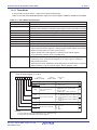
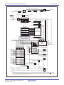
14. Three-Phase Motor Control Timer Function
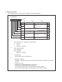
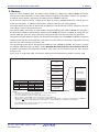
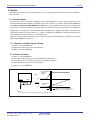
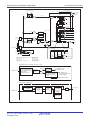
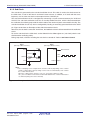
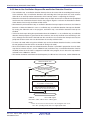
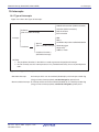
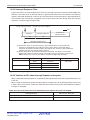
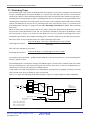
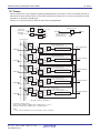
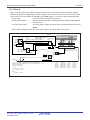
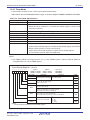
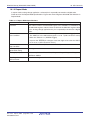
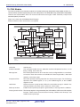
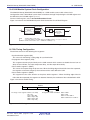
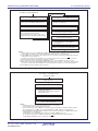
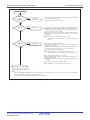
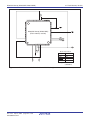
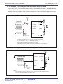
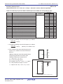
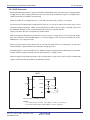
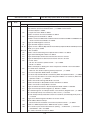
The three-phase motor control timer function is enabled by setting the INV02 bit in the INVC0 register to 1.
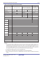
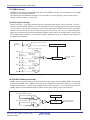
When this function is selected, timer B2 is used to__control
the carrier
wave, and timers A4, A1, and A2 are
___
___
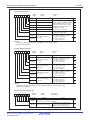
used to control three-phase PWM outputs (U, U, V, V, W, and W). The dead time is controlled by a
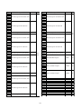
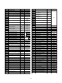
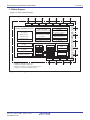
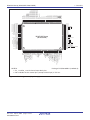
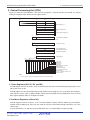
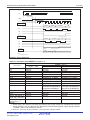
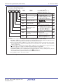
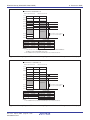
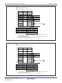
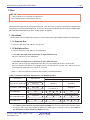
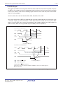
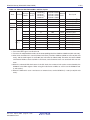
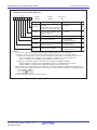
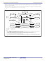
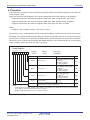
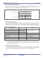
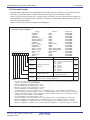
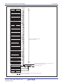
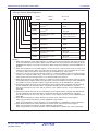
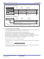
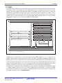
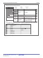
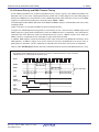
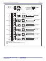
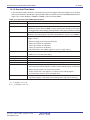
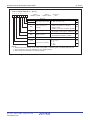
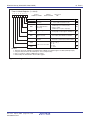
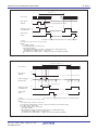
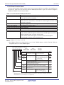
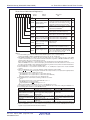
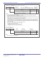
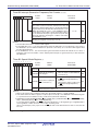
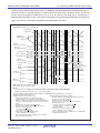
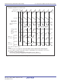
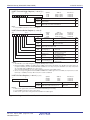
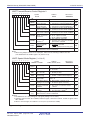
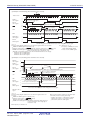
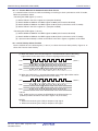
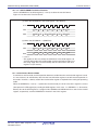
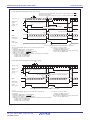
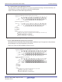
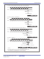
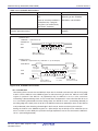
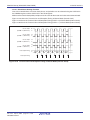
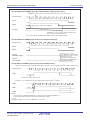
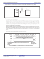
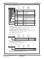
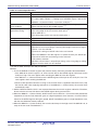
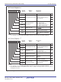
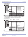
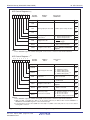
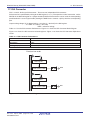
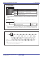
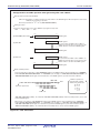
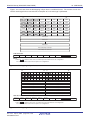
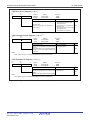
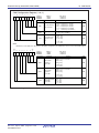
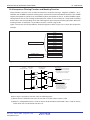
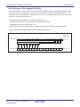
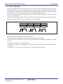
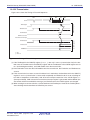
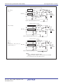
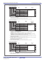
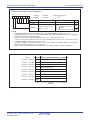
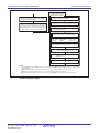
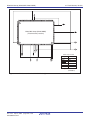
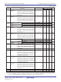
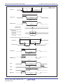
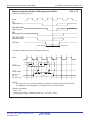
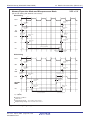
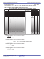
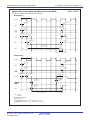
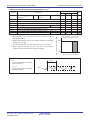
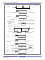
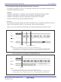
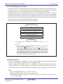
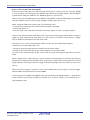
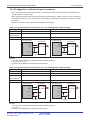
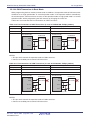
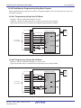
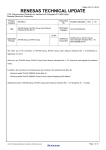
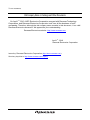
dedicated dead-time timer. Figure 14.9 shows an Example of Triangular Wave Modulation Opertation and
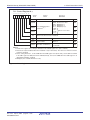
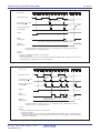
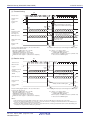
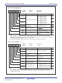
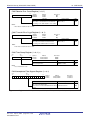
Figure 14.10 shows an Example of Sawtooth Wave Modulation Operation.
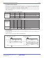
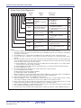
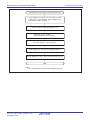
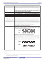
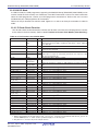
Triangular waveform as a carrier wave
Triangular Wave
Signal Wave
TB2S bit in
TABSR register
Timer B2
Timer A1
reload control signal (1)
Timer A4
(1)
start trigger signal
TA4 register (2)
m
n
p
q
r
TA4-1 register (2)
m
n
p
q
r
Reload register (2)
m
Timer A4
(1)
one-shot pulse
m
m
n
m
n
n
n
p
p
p
n
q
p
q
q
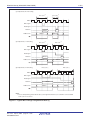
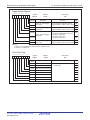
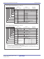
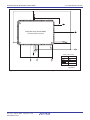
Rewrite registers IDB0 and IDB1
U-phase output
(1)
signal
Transfer a counter
value to the three-phase
shift register
U-phase output
signal(1)
INV14 = 0
("L" active)
q
U-phase
U-phase
Dead time
INV14 = 1
("H" active)
U-phase
Dead time
U-phase
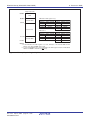
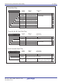
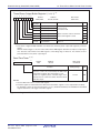
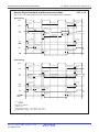
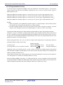
INV00, INV01: Bits in the INVC0 register
INV11, INV14: Bits in the INVC1 register
NOTES:
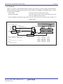
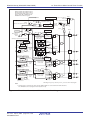
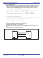
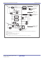
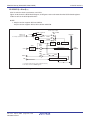
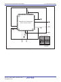
1.Internal signals. See Figure 14.1 Three-Phase Motor Control Timer Functions Block Diagram.
2.Applies only when the INV11 bit is set to 1 (three-phase mode).
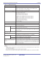
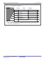
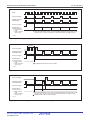
The above applies to INVC0 = 00XX11XXb and INVC1 = 010XXXX0b (X varies depending on each system.)
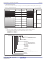
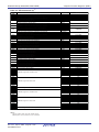
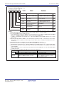
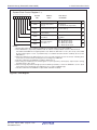
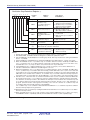
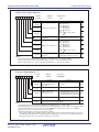
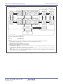
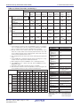
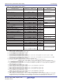
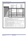
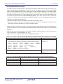
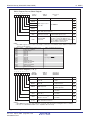
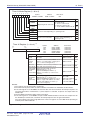
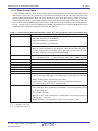
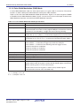
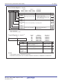
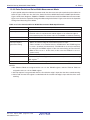
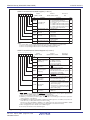
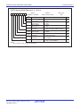
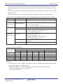
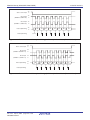
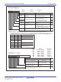
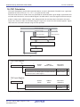
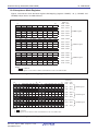
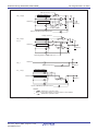
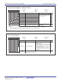
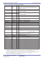
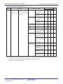
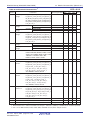
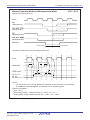
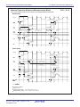
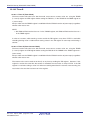
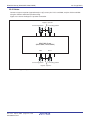
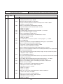
Examples of PWM output change are
(b) When INV11=0 (three-phase mode 0)
(a) When INV11=1 (three-phase mode 1)
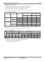
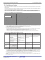
- INV01=0, ICTB2=1h (The timer B2 interrupt is generated
- INV01=0 and ICTB2=2h (The timer B2 interrupt is
whenever the timer B2 underflows)
generated with every second timer B2 underflow) or
- Default value of the timer: TA4=m
INV01= 1, INV00=1 and ICTB2=1h (The timer B2 interrupt is
The TA4 register is changed whenever the timer B2
generated on the falling edge of the timer A reload control
interrupt is generated.
signal)
First time: TA4=m. Second time: TA4=n.
- Default value of the timer: TA41=m, TA4=m
Third time: TA4=n. Fourth time: TA=p.
Registers TA4 and TA41 are changed whenever the
Fifth time: TA4=p.
timer B2 interrupt is generated.
- Default value of registers IDB0 and IDB1:
First time: TA41=n, TA4=n.
DU0=1, DUB0=0, DU1=0, DUB1=1
Second time: TA41=p, TA4=p.
They are changed to DU0=1, DUB0=0, DU1=1, DUB1=0 by
- Default value of registers IDB0 and IDB1
the sixth timer B2 interrupt.
DU0=1, DUB0=0, DU1=0, DUB1=1
They are changed to DU0=1, DUB0=0, DU1=1, DUB1=0
by the third timer B2 interrupt.
Figure 14.9 Triangular Wave Modulation Operation
Rev.2.10 Apr 14, 2006
REJ09B0124-0210
page 147 of 378