1
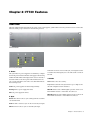
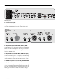
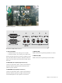
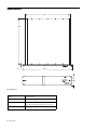
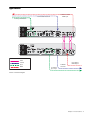
FT730 Guide
System 5
Legal Notices
This guide is copyrighted ©2011 by Avid Technology, Inc., (hereafter “Avid”), with
all rights reserved. Under copyright laws, this guide may not be duplicated in
whole or in part without the written consent of Avid.
003, 96 I/O, 96i I/O, 192 Digital I/O, 192 I/O, 888|24 I/O, 882|20 I/O,
1622 I/O, 24-Bit ADAT Bridge I/O, AudioSuite, Avid, Avid DNA, Avid Mojo,
Avid Unity, Avid Unity ISIS, Avid Xpress, AVoption, Axiom, Beat Detective,
Bomb Factory, Bruno, C|24, Command|8, Control|24, D-Command, D-Control,
D-Fi, D-fx, D-Show, D-Verb, DAE, Digi 002, DigiBase, DigiDelivery, Digidesign,
Digidesign Audio Engine, Digidesign Intelligent Noise Reduction, Digidesign
TDM Bus, DigiDrive, DigiRack, DigiTest, DigiTranslator, DINR, DV Toolkit,
EditPack, Eleven, HD Core, HD I/O, HD MADI, HD OMNI, HD Process, Hybrid,
Impact, Interplay, LoFi, M-Audio, MachineControl, Maxim, Mbox,
MediaComposer, MIDI I/O, MIX, MultiShell, Nitris, OMF, OMF Interchange, PRE,
ProControl, Pro Tools, Pro Tools|HD, QuickPunch, Recti-Fi, Reel Tape, Reso,
Reverb One, ReVibe, RTAS, Sibelius, Smack!, SoundReplacer, Sound
Designer II, Strike, Structure, SYNC HD, SYNC I/O, Synchronic, TL Aggro,
TL AutoPan, TL Drum Rehab, TL Everyphase, TL Fauxlder, TL In Tune,
TL MasterMeter, TL Metro, TL Space, TL Utilities, Transfuser, Trillium Lane Labs,
Vari-Fi, Velvet, X-Form, and XMON are trademarks or registered trademarks of
Avid Technology, Inc. Xpand! is Registered in the U.S. Patent and Trademark
Office. All other trademarks are the property of their respective owners.
Product features, specifications, system requirements, and availability are
subject to change without notice.
Guide Part Number 9329-65140-00 REV A 08/11
Documentation Feedback
We are always looking for ways to improve our documentation. If you have
comments, corrections, or suggestions regarding our documentation, email us
at [email protected].
Contents
Chapter 1. Introduction to the FT730 . . . . . . . . . . . . . . . . . . . . . . . . . . . . . . . . . . . . . . . . . . . . . . . . . . . . . . . . . . . . . . . 1
System Requirements and Compatibility . . . . . . . . . . . . . . . . . . . . . . . . . . . . . . . . . . . . . . . . . . . . . . . . . . . . . . . . . . . . . 1
About This Guide. . . . . . . . . . . . . . . . . . . . . . . . . . . . . . . . . . . . . . . . . . . . . . . . . . . . . . . . . . . . . . . . . . . . . . . . . . . . . . 1
About www.avid.com . . . . . . . . . . . . . . . . . . . . . . . . . . . . . . . . . . . . . . . . . . . . . . . . . . . . . . . . . . . . . . . . . . . . . . . . . . . 2
Chapter 2. FT730 Features . . . . . . . . . . . . . . . . . . . . . . . . . . . . . . . . . . . . . . . . . . . . . . . . . . . . . . . . . . . . . . . . . . . . . . . . 3
Front Panel. . . . . . . . . . . . . . . . . . . . . . . . . . . . . . . . . . . . . . . . . . . . . . . . . . . . . . . . . . . . . . . . . . . . . . . . . . . . . . . . . . 3
Back Panel . . . . . . . . . . . . . . . . . . . . . . . . . . . . . . . . . . . . . . . . . . . . . . . . . . . . . . . . . . . . . . . . . . . . . . . . . . . . . . . . . . 4
Specifications . . . . . . . . . . . . . . . . . . . . . . . . . . . . . . . . . . . . . . . . . . . . . . . . . . . . . . . . . . . . . . . . . . . . . . . . . . . . . . . . 6
Applications . . . . . . . . . . . . . . . . . . . . . . . . . . . . . . . . . . . . . . . . . . . . . . . . . . . . . . . . . . . . . . . . . . . . . . . . . . . . . . . . . 7
Technical Reference . . . . . . . . . . . . . . . . . . . . . . . . . . . . . . . . . . . . . . . . . . . . . . . . . . . . . . . . . . . . . . . . . . . . . . . . . . . 8
Appendix A. Compliance Information . . . . . . . . . . . . . . . . . . . . . . . . . . . . . . . . . . . . . . . . . . . . . . . . . . . . . . . . . . . . . . . 9
Environmental Compliance. . . . . . . . . . . . . . . . . . . . . . . . . . . . . . . . . . . . . . . . . . . . . . . . . . . . . . . . . . . . . . . . . . . . . . . 9
EMC (Electromagnetic Compliance). . . . . . . . . . . . . . . . . . . . . . . . . . . . . . . . . . . . . . . . . . . . . . . . . . . . . . . . . . . . . . . . 10
Safety Compliance . . . . . . . . . . . . . . . . . . . . . . . . . . . . . . . . . . . . . . . . . . . . . . . . . . . . . . . . . . . . . . . . . . . . . . . . . . . 11
Contents iii
iv FT730 Guide
Chapter 1: Introduction to the FT730
The FT730 FiberTran Fiberoptic Extender allows an ML530 Microphone/Line preamplifier or MC524 Monitor Controller to
be placed up to 3300 ft (1 km) away from the processing core
of an Avd Pro Series digital console. The FT730 is always used
in pairs with one local unit at the control end and one remote
unit at the far end connected by up to 1 km of fiberoptic cable.
Normally, four fibers are used:
• One pair sends audio sync and control information to
the remote end and receives status information back.
About This Guide
This guide provides a basic overview of FT730 features and
functionality.
For complete instructions on connecting and configuring
your system, see the System 5 Installation Guide.
Conventions Used in This Guide
• The second pair sends and receives MADI.
The same device is used at both ends but their functionality
differs: If a sync source is connected (AES or word clock), it is
a local unit; otherwise, the device looks for sync on the sync fiber and, if found, behaves as a remote unit.
System Requirements and
Compatibility
Avid can only assure compatibility and provide support for
hardware and software it has tested and approved.
For complete system requirements and a list of qualified
computers, operating systems, hard drives, and third-party
devices, visit www.avid.com/compatibility.
All of our guides use the following conventions to indicate
menu choices and key commands:
:
Convention
Action
File > Save
Choose Save from the File menu
Control+N
Hold down the Control key and press
the N key
Control-click
Hold down the Control key and click the
mouse button
Right-click
Click with the right mouse button
The names of Commands, Options, and Settings that appear
on-screen are in a different font.
The following symbols are used to highlight important
information:
User Tips are helpful hints for getting the most from
your system.
Important Notices include information that could affect
your data or the performance of your system.
Shortcuts show you useful keyboard or mouse shortcuts.
Cross References point to related sections in this guide and
other Avid guides.
Chapter 1: Introduction to the FT730 1
About www.avid.com
The Avid website (www.avid.com) is your best online source
for information to help you get the most out of your system.
The following are just a few of the services and features
available.
Product Registration Register your purchase online.
Support and Downloads Contact Avid Customer Success (technical support); download software updates and the latest online manuals; browse the Compatibility documents for system
requirements; search the online Knowledge Base or join the
worldwide Avid user community on the User Conference.
Training and Education Study on your own using courses available online or find out how you can learn in a classroom setting at a certified Avid training center.
Products and Developers Learn about Avid products; download demo software or learn about our Development Partners
and their plug-ins, applications, and hardware.
News and Events Get the latest news from Avid or sign up for
a demo.
2 FT730 Guide
Chapter 2: FT730 Features
Front Panel
The front panel has LEDs that indicate the status of the power supplies, synchronization activity, and the status of several other
functions. Each group is discussed in the following sections.
FT730 Front Panel
3
2
1
FT730 front panel (detail)
1. Power
The system has two power supplies for redundancy. A simple
monitoring circuit checks whether each supply is functioning
within allowable limits and displays their status on the PSU 1
and PSU 2 LEDs on the front panel. The information is also
sent over the fiber link to the remote end. The LEDs indicate
the following status:
Solid Both power supplies are functioning normally.
Flashing Remote power supply has failed.
Off Local power supply has failed.
2. Sync
If the unit is locked to Word or AES sync, it is designated as the
local unit and sends digital sync to the remote unit over the fiber link.
3. Status
TCC Indicates TCC data activity.
Loop Indicates that the TCC/Sync fiber loop is complete and
the time of flight has been calculated.
MADI IN Indicates that a MADI signal is present on the 75-W
BNC MADI In and also on the Fiber TX connector.
MADI OUT Indicates that a MADI signal is present on the 75-W
BNC MADI Out and also on the Fiber RX connector.
Remote The unit is locked to sync coming from the local unit
over the fiber link.
Word The unit is locked to sync on the word clock sync input.
AES The unit is locked to sync on the AES sync input.
Chapter 2: FT730 Features 3
Back Panel
1
1
I
O
I
O
FT730 back panel
1. Power Connectors (IEC)
Accepts two standard IEC power cords (provided). Two autoranging switching supplies accept voltages in the range
100–240 VAC, 50–60 Hz.
1
FT730 back panel (detail)
1. AES/SYNC IN (female XLR or BNC), WORD IN (BNC)
Connect this port to a digital sync reference (local unit only).
Selection for XLR or BNC input is done using two internal
jumpers shown in Figure 4. The unit is shipped with the jumpers set for the XLR input.
2. AES/SYNC OUT (male XLR or BNC), WORD OUT (BNC)
Connect one of these ports to the digital sync reference input
of any device receiving MADI at the remote unit. Only one
output connection (XLR or BNC) should be used at a time.
3. RETIMED AES/SYNC OUT (male XLR), RETIMED WORD
OUT (BNC)
Connect one of these ports to the digital sync reference input
of any device sending MADI from the remote unit back to the
local unit. See Synchronization for Distances Over 800 ft (250
m) on page 13 for more information about these outputs.
4 FT730 Guide
2
3
BNC
XLR
Internal sync input jumper
1
2
4
3
5
1
Back panel TCC, MADI, and fiber connectors
1. TCC IN/Out (DB15)
• Connect TCC IN to TCC control port at local unit.
4. MADI IN (BNC)
MADI connection for signal being transmitted over fiber.
• Connect TCC OUT to TCC control port at remote unit.
Because the same unit is used at both ends, each has a TCC IN
and a TCC OUT connector. However, only the TCC IN is intended to be used at the local end and the TCC OUT at the remote end.
5. MADI OUT (BNC)
MADI connection for signal being received from fiber.
2. FIBER SYNC/TCC TX/RX (ST Optical Connector)
Connects local and remote units. Connect local RX and TX to
remote TX and RX, respectively. Both connections are required for proper operation.
3. FIBER MADI TX/RX (ST Optical Connector)
Connects local and remote units. Connect local RX and TX to
remote TX and RX, respectively. A single connection can be
used if MADI signals are only required for one direction.
Chapter 2: FT730 Features 5
Specifications
16.92"
17.00"
19.00"
.40"
3.47"
(2RU)
FT730 dimensions
Weight
11.6 lb (5.2 kg)
Power
25 W
Cable Requirements
The FT730’s fiber transceivers work only with
62.5/125 mm multimode fiber with ST connectors.
Maximum Fiber Distance
3300 ft (1000 m)
6 FT730 Guide
Applications
To DF64 or SH612
MADI Input
From PC253i TCC Port
From Sync Distribution
I
O
I
O
I
O
I
O
Fiber
Control
Sync
MADI
To AM713
Sync Input
To ML530
TCC Port
From AM713
MADI Output
FT730 connection diagram
Chapter 2: FT730 Features 7
Technical Reference
Synchronization for Distances Over 800 ft (250 m)
MADI utilizes a polarity-free, serial NRZI (non-return-to-zero
inverted) protocol with encoding at 125 Mbit/s (±100 ppm).
Sample timing is controlled independently by distributing a
master synchronization signal. Originally, the transmission
medium was 75-W coaxial cable. There are two important synchronization issues:
• The MADI signal’s transmitted frame start time must be
within 5% of the sample period time determined by the synchronizing signal.
This requirement is usually met by the circuit design using
the distributed synchronization signal.
• The received frame start time must be within ±25% of the
sample period reference time.
This requirement is governed by physics: it is the time of
flight (delay time) difference between the sample start
and the start of the frame. The speed of light
(299,792,458 m/s) and the propagation speed of the
transmission medium govern this delay time.
Transmission mediums, such as fiber and coaxial cable, have
propagation speeds in the range 60–70% of the speed of light.
This does not present a problem when MADI and the synchronization signal are sent together to a destination, such as a
MA703. The problem manifests when MADI is used to return
data from a source such as an AM713, where the delay time
difference for the MADI and synchronization signals exceeds
the received frame start time requirement (±25% of the sample period reference time).
The FT730 has two types of synchronization outputs:
AES/Sync or Word Out Used for devices receiving MADI at the
remote end. These outputs are used if the signal meets the criteria stated in the first bullet above.
Retimed AES or Retimed Word Sync Used for devices transmitting MADI to the local end. The control/sync fiber pair is used
to measure at the local end by comparing the local sync timing with that returned from the remote end. This number is
sent to the remote end where the timing is adjusted in sixteenth frame increments to keep it within the operational requirements stated in the second bullet above.
8 FT730 Guide
Single Mode vs. Multimode Fiber Optic Cable
In optical fiber technology, multimode fiber is optical fiber
that is designed to carry multiple light rays (modes) concurrently. Each mode is carried at a slightly different reflection
angle within the optical fiber core. Multimode fiber transmission is used for relatively short distances (less than 6500
ft/2000 m) because the modes tend to disperse over longer
lengths (modal dispersion). For distances longer than 6500 ft
(2000 m), single mode fiber (sometimes called monomode) fiber is used. Multimode fiber has a typical core diameter of
50–100 mm with a refractive index that is graded or stepped.
It allows the use of inexpensive LED light sources, and connector alignment and coupling is less critical than for single
mode fiber. This translates into lower connection and electronics costs and consequently lower overall system costs. The
FT730 uses 62.5/125 mm multimode fiber with ST connectors.
Appendix A: Compliance Information
Environmental Compliance
Disposal of Waste Equipment by Users in the
European Union
Proposition 65 Warning
This product contains chemicals, including lead,
known to the State of California to cause cancer
and birth defects or other reproductive harm.
Wash hands after handling.
Perchlorate Notice
This product may contain a lithium coin battery. The State of California requires
the following disclosure statement: “Perchlorate Material – special handling may
apply, See www.dtsc.ca.gov/hazardouswaste/perchlorate.”
This symbol on the product or its packaging indicates that this product must not
be disposed of with other waste. Instead, it is your responsibility to dispose of
your waste equipment by handing it over to a designated collection point for the
recycling of waste electrical and electronic equipment. The separate collection
and recycling of your waste equipment at the time of disposal will help conserve
natural resources and ensure that it is recycled in a manner that protects human
health and the environment. For more information about where you can drop off
your waste equipment for recycling, please contact your local city recycling office
or the dealer from whom you purchased the product.
Recycling Notice
Appendix A: Compliance Information 9
EMC (Electromagnetic Compliance)
Avid declares that this product complies with the following standards regulating
emissions and immunity:
• FCC Part 15 Class A
• EN55103-1 E4
• EN55103-2 E4
• AS/NZS CISPR 22 Class A
• CISPR 22 Class A
FCC Compliance for United States
Communication Statement
Note: This equipment has been tested and found to comply
with the limits for a Class A digital device, pursuant to part
15 of the FCC Rules. These limits are designed to provide
reasonable protection against harmful interference when the
equipment is operated in a commercial environment. This
equipment generates, uses, and can radiate radio frequency
energy and, if not installed and used in accordance with the
instruction manual, may cause harmful interference to radio
communications. Operation of this equipment in a
residential area is likely to cause harmful interference in
which case the user will be required to correct the
interference at his own expense.
Any modifications to the unit, unless expressly approved by
Avid, could void the user's authority to operate the
equipment.
10 FT730 Guide
Australian Compliance
N1709
Canadian Compliance
This Class A digital apparatus meets all requirements of the Canadian
Interference-Causing Equipment Regulations.
Cet appareil numérique de la classe A respecte toutes les exigences du
Règlement sur le material brouilleur du Canada.
CE Compliance
(EMC and Safety)
Avid is authorized to apply the CE (Conformité Europénne) mark on this compliant
equipment thereby declaring conformity to EMC Directive 2004/108/EC and Low
Voltage Directive 2006/95/EC.
Safety Compliance
Safety Statement
This equipment has been tested to comply with USA and Canadian safety
certification in accordance with the specifications of UL Standards:
UL 60950-1:2007, 2nd Ed and CAN/CSA-22.2 No. 60950-1-07, 2nd Ed.
Avid Inc., has been authorized to apply the appropriate NRTL mark on its
compliant equipment.
Warning
13) Unplug this equipment during lightning storms or when unused for long
periods of time.
14) Refer all servicing to qualified service personnel. Servicing is required when
the equipment has been damaged in any way, such as power-supply cord or plug
is damaged, liquid has been spilled or objects have fallen into the equipment,
the equipment has been exposed to rain or moisture, does not operate normally,
or has been dropped.
15) For products that are a Mains powered device:
The equipment shall not be exposed to dripping or splashing and no objects filled
with liquids (such as vases) shall be placed on the equipment.
Warning! To reduce the risk of fire or electric shock, do not expose this
equipment to rain or moisture.
16) For products containing a lithium battery:
CAUTION! Danger of explosion if battery is incorrectly replaced. Replace only
with the same or equivalent type.
17) For products with a power switch:
It should remain accessible after installation.
18) The equipment shall be used at a maximum ambient temperature of 40° C.
Important Safety Instructions
1) Read these instructions.
19) This unit is provided with a power supply cord set suitable for 120V AC input
only (for U.S.A.and Canada). For other than U.S.A. and Canada, a qualified
person must provide for use with this unit, an appropriate, approved power
supply cord set which is in compliance with the end use country requirements
and has a minimum cross-sectional area of 1.0mm2.
2) Keep these instructions.
20) For units with more than one power cord:
3) Heed all warnings.
CAUTION: This unit has more than one power supply cord. Disconnect two power
supply cords before servicing to avoid electrical shock.
4) Follow all instructions.
5) Do not use this equipment near water.
6) Clean only with dry cloth.
7) Do not block any ventilation openings. Install in accordance with the
manufacturer’s instructions.
8) Do not install near any heat sources such as radiators, heat registers, stoves,
or other equipment (including amplifiers) that produce heat.
9) Do not defeat the safety purpose of the polarized or grounding-type plug. A
polarized plug has two blades with one wider than the other. A grounding type
plug has two blades and a third grounding prong. The wide blade or the third
prong are provided for your safety. If the provided plug does not fit into your
outlet, consult an electrician for replacement of the obsolete outlet.
ATTENTION: Cet appareil comporte plus d’un cordon d’alimentation. Afin de
prévenir les chocs électriques, débrancher les deux cordons d’alimentation
avant de faire le dépannage.
21) For products with an operator-accessible fuse:
CAUTION: For continued protection against risk of fire, replace only with same
type and rating of fuse.
ATTENTION: Pour ne pas compromettre la protection contre les risques
d’incendie, remplacer par un fusible de même type et de même caractéristiques
nominales.
10) Protect power cords from being walked on or pinched particularly at plugs,
convenience receptacles, and the point where they exit from the equipment.
11) Only use attachments/accessories specified by the manufacturer.
12) For products that are not rack-mountable: Use only with a cart, stand, tripod,
bracket, or table specified by the manufacturer, or sold with the equipment.
When a cart is used, use caution when moving the cart/equipment combination
to avoid injury from tip-over.
Appendix A: Compliance Information 11
12 FT730 Guide
Avid
Technical Support (USA)
Product Information
2001 Junipero Serra Boulevard
Daly City, CA 94014-3886 USA
Visit the Online Support Center at
www.avid.com/support
For company and product information,
visit us on the web at www.avid.com