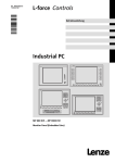
1
Industrial PC Ä.1nDä LDCDS-11225 .1nD Gerätehandbuch Hardware Manual Monitor Panel MP 600-9000 DVI Einbau Monitor mit TFT-Display Mounting of monitor with TFT display © 2007 Lenze Digitec Controls GmbH, Grünstr. 36, D-40667 Meerbusch Ohne besondere schriftliche Genehmigung von Lenze Digitec Controls GmbH darf kein Teil dieser Dokumentation vervielfältigt oder Dritten zugänglich gemacht werden. Wir haben alle Angaben in dieser Dokumentation mit größter Sorgfalt zusammengestellt und auf Übereinstimmung mit der beschriebenen Hard- und Software geprüft. Trotzdem können wir Abweichungen nicht ganz ausschließen. Wir übernehmen keine juristische Verantwortung oder Haftung für Schäden, die dadurch eventuell entstehen. Notwendige Korrekturen werden wir in die nachfolgenden Auflagen einarbeiten. © 2007 Lenze Digitec Controls GmbH, Grünstr. 36, D-40667 Meerbusch No part of this documentation may be reproduced or made accessible to third parties without written consent by Lenze Digitec Controls GmbH. All information given in this documentation has been selected carefully and complies with the hardware and software described. Nevertheless, discrepancies cannot be ruled out. We do not take any responsibility or liability for any damage that may occur. Necessary corrections will be included in subsequent editions. Inhaltsverzeichnis 1 2 Zu diesem Handbuch ___________________________________________ 3 1.1 Status _______________________________________________________________ 3 1.2 Abkürzungen _________________________________________________________ 3 1.3 Zitierte Normen _______________________________________________________ 4 Wichtige Hinweise _____________________________________________ 5 2.1 3 Technische Daten ______________________________________________________ 6 Gerätebeschreibung____________________________________________ 7 3.1 Allgemeines __________________________________________________________ 7 3.1.1 Monitor-Panel _____________________________________________________ 8 3.2 Bedienelemente der Frontplatten__________________________________________ 9 3.2.1 MP600/ MP1000/ MP1000s/ MP2000/ MP5000/ MP9000 "Touch"_____________ 9 3.2.2 MP5020 "Touch plus F-/S-Tasten" _____________________________________ 10 3.2.3 MP1050/ MP1050s/ MP2050/ MP5050 "Touch plus Num-, Alpha-, F-Tasten" ____ 11 3.2.4 MP5070 "Touch plus Num-, Sonder-, F-Tasten und MF2" ____________________ 12 3.2.5 Option frontseitige USB-Buchse ______________________________________ 13 3.3 Anschlüsse des Monitor-Panels __________________________________________ 14 3.3.1 Versorgungs-Spannungsanschluss ____________________________________ 14 3.3.2 USB in (upstream) _________________________________________________ 14 3.3.3 USB out (downstream) _____________________________________________ 15 3.3.4 DVI Anschluss ____________________________________________________ 15 3.3.5 DVI/USB-Extender _________________________________________________ 16 3.3.6 Erdungsschraube__________________________________________________ 16 4 Montage, Einbau und Wartung __________________________________ 17 4.1 Montage des Monitor-Panel _____________________________________________ 18 4.1.1 Montage mit Schraubspannern _______________________________________ 19 4.1.2 Einbauausschnitte des Monitor-Panel __________________________________ 20 4.2 5 6 Bedienung und Reinigung des Touchscreens ________________________________ 21 Abmaße und Einbauraum ______________________________________ 22 5.1.1 Abmaße der Monitor-Panel __________________________________________ 22 Ersatzteile und Zubehör ________________________________________ 23 1 Abbildungsverzeichnis Abbildung 1 Abbildung 2 Abbildung 3 Abbildung 4 Abbildung 5 Abbildung 6 Abbildung 7 Abbildung 8 Abbildung 9 Abbildung 10 2 Systemübersicht EL-Serie ___________________________________________ 8 Front MPx000 ___________________________________________________ 9 Front MP5020 __________________________________________________ 10 Front MPx050 __________________________________________________ 11 Front MP5070 __________________________________________________ 12 Anschlussseite MP-Serie __________________________________________ 14 Erdungskontakt _________________________________________________ 16 Montageanleitung Schraubspanner _________________________________ 19 Montageausschnitt MP-Serie_______________________________________ 20 Maße MP-Serie________________________________________________ 22 1 Zu diesem Handbuch Kapitelverweise sind kursiv dargestellt. Beispiel: Siehe Kapitel 1 Zu diesem Handbuch Wichtige Informationen sind in einem grauen Rahmen hinterlegt. Beispiel: Wichtig! Bitte lesen Sie dieses Handbuch! 1.1 Status Datum 01.09.2005 25.10.2006 1.2 Version 1.0 2.0 Kapitel Alle Alle Beschreibung Erstellt Redaktionell überarbeitet Abkürzungen Kurzbezeichnung AP CF oder CF-Card CPC EL Gerät IPC MP LDC Panel-PC, Flach-Display-Rechner PC, Rechner Bezeichnung Automation Panel Compact Flash-Karte Schaltschrank-PC (Serie CPC) Embedded Line Als Gerät werden in diesem Dokument beide Serien (CPC und EL) bezeichnet Industrie-PC Monitor Panel Lenze Digitec Controls GmbH Embedded Line Panel-PC (Serie EL) Personal Computer, hier Serie CPC und EL zusammengefasst 3 1.3 Zitierte Normen Kurzbezeichnung Ergonomierichtlinie ZH 1/618 DIN 41494 DIN EN 60950 IEC 61000/EN 61000/ VDE 0847: -4-2, -4-3, -4-4 und -4-6 ISO 16016 VDE 0113 VDE 0160 VDE 0750 (DIN EN 60601-1) VDE 0805 / DIN EN 60950 VDE 0870 4 Bezeichnung Sicherheitsregeln für Bildschirmarbeitsplätze im Bürobereich Bauweisen für elektronische Einrichtungen; 482, 6-mm-Bauweise Einrichtungen der Informationstechnik- Sicherheit Elektromagnetische Verträglichkeit (EMV) - Umgebungsbedingungen Technische Produktdokumentation Schutzvermerke zur Beschränkung der Nutzung von Dokumenten und Produkten Sicherheit von Maschinen (…) Ausrüstung von Starkstromanlagen mit elektronischen Betriebsmitteln Medizinische elektrische Geräte Einrichtungen der Informationstechnik - Sicherheit Elektromagnetische Beeinflussung (EMB) 2 Wichtige Hinweise Bitte lesen Sie diese Anleitung, bevor sie das Gerät benutzen! Beachten Sie unbedingt Kapitel 2.1 Technische Daten • Dieser Computer ist ein Einbauteil! Der Einbau muss in Übereinstimmung mit DIN EN 60950, VDE 0160, VDE 0113 und VDE 0750 (DIN EN 60601-1) erfolgen. • Der Computer entspricht der Schutzklasse 1. Der Schutzleiter des Versorgungssteckers ist mit dem Metallgehäuse des Gerätes verbunden. • Um das Gerät spannungsfrei zu schalten, muss der Versorgungsspannungsstecker abgezogen werden. • Das Gerät darf nur von qualifiziertem Personal geöffnet werden. Siehe Kapitel 4 Montage, Einbau • Die im Flach-Display-Rechner integrierte Kurzhub-Tastatur und das Display entsprechen nicht der Ergonomierichtlinie ZH 1/618. Tastatur und Display sind nur für kurzzeitige Eingaben und Kontrollfunktionen ausgelegt. • Der Dichtungsring der Frontplatte des Flach-Display-Rechners ist bei Lagerung vor UV-Strahlung zu schützen. • Im Falle eines Fehlers ist das Gerät an den Hersteller mit folgender Adresse zurückzuschicken (Bei Rücksendung bitte die Originalverpackung verwenden!): Lenze Digitec Controls GmbH, Germany Grünstraße 36 • 40667 Meerbusch Tel. +49 – 2132 / 9904 – 0 Homepage: http://www.lenze-digitec.de E-Mail: [email protected] 5 2.1 Technische Daten Spannungsversorgung Leistungsaufnahme Steckverbinder Sicherheit Emissionen Schock Temperatur Luftfeuchtigkeit Schutzart Schutzklasse Max. Abmaße Gerätetyp MP600 MP1000 MP1000s MP1050 MP1050s MP2000 MP2050 MP5000 MP5020 MP5050 MP5070 MP9000 24 V DC (18 ... 30 V), max. Stromaufnahme bei MP9000: 2,4 A max. 50 W Eingangsspannungsstecker Typ Phönix COMBICON, MSTB 2,5/ 3-STF-5,08 VDE 0805 (EN 60950), VDE 0870, UL CE-Sign, EN 50082 (IEC 1000-2, -3, -4), EN 50081 (EN 55022) 10 g / 11 ms (IEC 68) 5 bis 50 °C (in Betrieb) -10 bis 60 °C (Lagerung) min. 10 % bis max. 90 % (nicht kondensierend) IP20; Front der EL-Serie bei fachgerechter Montage IP65 Schutzklasse 1 Siehe Kapitel 5 Abmaße und Einbau Mindestgewicht Grundgerät 2,4 kg 4,2 kg 4,2 kg 4,6 kg 4,6 kg 5,4 kg 5,6 kg 6,2 kg 6,4 kg 6,4 kg 7,2 kg 10,2 kg Der Monitor-Panel darf nicht im Ex-Bereich eingesetzt werden. Wird das Gerät in ein separates Umgehäuse eingebaut, ist darauf zu achten, dass die maximale Umgebungstemperatur von 45 °C Spitze (<35 °C Durchschnittstemperatur) nicht überschritten wird. Falls nötig, sind entsprechende Maßnahmen zur passiven oder aktiven Kühlung vorzusehen. Alle Angaben ohne Gewähr: Die Firma Lenze Digitec Controls GmbH behält sich Änderungen, insbesondere der angegebenen Werte, Maße und Gewichte vor, sofern diese nicht anders vermerkt sind. 6 3 Gerätebeschreibung 3.1 Allgemeines Der Monitor-Panel ist für eine dezentrale IPC-Lösungen (Bedieneinheit abgesetzt vom Rechner) entwickelt worden. Der Monitor-Panel kann in einen Schaltschrank oder eine Maschine eingebaut werden. Die mechanischen Abmessungen sind in Kapitel 5 Abmaße und Einbau aufgeführt. Hinweis Alle Arbeiten an dem Gerät sind bei abgezogener Versorgungsspannung durchzuführen. Dies ist erforderlich bei: a) Öffnen des Gehäuses b) Austausch von Komponenten oder Erweiterungskarten c) Konfiguration der Hardware d) Anschließen und Abziehen der Steckverbinder: Serielle und parallele Schnittstellen, usw. 7 3.1.1 Monitor-Panel Der Monitor-Panel ist ein speziell für die Industrie entwickelter Kompakt-Monitor mit Eingabemöglichkeit. Das Gerät basiert auf einer Folienfrontplatte mit Display und Touch-Screen (Optional mit Glasscheibe ohne Touch-Funktion). Die Modelle MP2050, MP5050 und MP5070 können in 19"-Schaltschränke (nach DIN 41494) eingebaut werden. Die Frontfolie ist eine hochbeständige Polyester Folie. Abhängig vom Einbau des Gerätes kann für die Front die Schutzklasse IP65 erreicht werden. Pflege des Touchscreens siehe Kapitel 4.2 Bedienung und Reinigung des Touchscreens Displayauflösung: Typ MP600 MP1000, MP1050 MP1000s, MP1050s MP2000, MP2050 MP5000, MP5020, MP5050, MP5070 MP9000 Abbildung 1 8 Systemübersicht EL-Serie Display 6,4 " 10,4 " 10,4 " 12,1 " 15,0 " 19,0 " Auflösung 640 x 480 640 x 480 800 x 600 800 x 600 1.024 x 768 1.280 x 1.024 VESA-Standard VGA VGA SVGA SVGA XGA SXGA 3.2 Bedienelemente der Frontplatten 3.2.1 MP600/ MP1000/ MP1000s/ MP2000/ MP5000/ MP9000 "Touch" Abbildung 2 Front MPx000 Status-LEDs Power Fail Status Funktionstasten "F1" / "Werkzeug" "F2" / "+": "F3" / "-": "X" Die Power-LED leuchtet grün, wenn die Versorgungsspannung vorhanden ist. Wenn die LED blinkt, ist der Service-Modus aktiviert, in dem die DisplayHelligkeit eingestellt werden kann. Bei schnellem Blinken ist die USB-Verbindung unterbrochen. Die Fail-LED leuchtet rot, wenn ein Fehler in der Stromversorgung vorliegt. Wenn die LED blinkt, ist das Display-Signal unterbrochen. Die Status-LED zeigt den Zugriff auf das Speichermedium an (z. B. Festplatte oder Compact Flash). Standard-Modus: Die Taste sendet den Tastencode für "SHIFT+F1" Standard-Modus: Die Taste sendet den Tastencode für "SHIFT+F2" Service-Modus: Erhöht die Display-Helligkeit ⇑. Standard-Modus: Die Taste sendet den Tastencode für "SHIFT+F3" Service-Modus: Verringert die Display-Helligkeit ⇓. Um in den Service Modus zu wechseln, muss die Taste für mindestens 3 Sekunden gedrückt werden, bis die grüne Power-LED blinkt. Während die LED blinkt, kann die Display-Helligkeit verändert werden. Um in den Standard-Modus zurückzukehren, kann die "X"-Taste erneut gedrückt werden oder 35 Sekunden warten. 9 3.2.2 MP5020 "Touch plus F-/S-Tasten" Abbildung 3 Front MP5020 Status LEDs siehe 3.2.1 MP600/ MP1000/ MP1000s/ MP2000/ MP5000/ MP9000 "Touch" Funktionstasten "F1" / "Werkzeug" "F2" / "+": "F3" / "-": "F4" / "X" Standard-Modus: Die Taste sendet den Tastencode für "F1" Standard-Modus: Die Taste sendet den Tastencode für "F2" Service-Modus: Erhöht die Display-Helligkeit ⇑. Standard-Modus: Die Taste sendet den Tastencode für "F3" Service-Modus: Verringert die Display-Helligkeit ⇓. Um in den Service Modus zu wechseln, muss die Taste für mindestens 3 Sekunden gedrückt werden, bis die grüne Power-LED blinkt. Während die LED blinkt, kann die Display-Helligkeit verändert werden. Um in den Standard-Modus zurückzukehren, kann die "X"-Taste erneut gedrückt werden oder 35 Sekunden warten. Die weiteren Funktionstasten ("F5" bis "F12") entsprechen der Kodierung einer handelsüblichen MF2-Tastatur. Die 14 Sonder-Tasten sind werkseitig frei belegbar. 10 3.2.3 MP1050/ MP1050s/ MP2050/ MP5050 "Touch plus Num-, Alpha-, FTasten" Abbildung 4 Front MPx050 Status LEDs siehe 3.2.1 MP600/ MP1000/ MP1000s/ MP2000/ MP5000/ MP9000 "Touch" Funktionstasten siehe 3.2.2 MP5020 "Touch plus F-/S-Tasten" Alpha-Taste "Alpha" Durch Betätigen der Alpha-Taste wird dauerhaft auf die zweite Tastaturebene umgeschaltet. Die Alpha-LED leuchtet dann konstant. Durch nochmaliges Betätigen der Alpha-Taste wird der Modus zurückgesetzt. Die Funktionalität der anderen Tasten entspricht der Kodierung einer handelsüblichen MF2-Tastatur. 11 3.2.4 MP5070 "Touch plus Num-, Sonder-, F-Tasten und MF2" Abbildung 5 Front MP5070 Status LEDs siehe 3.2.1 MP600/ MP1000/ MP1000s/ MP2000/ MP5000/ MP9000 "Touch" Funktionstasten siehe 3.2.2 MP5020 "Touch plus F-/S-Tasten" Die Funktionalität der anderen Tasten entspricht der einer handelsüblichen MF2-Tastatur. 12 3.2.5 Option frontseitige USB-Buchse Optional ist ein frontseitiger USB-Anschluss (Typ A) mit Schutzart IP65 erhältlich. Hinweis! Die Datensicherheit des Systems ist unter Umständen nicht mehr gewährleistet, da über USB-Geräte ein Datenzugriff erfolgen kann. Auf der mitgelieferten CD ist ein Zusatztool (FM-Tool) enthalten, mit dem der frontseitige USB-Anschluss aktiviert/deaktiviert werden kann. Steckerbelegung siehe Kapitel 3.3.3 USB out (downstream) 13 3.3 Anschlüsse des Monitor-Panels Abbildung 6 Anschlussseite MP-Serie Video input USB input USB output Versorgungsspannung 24 V DC 3.3.1 DVI-D (Bildschirmverbindung zum Rechner 1x USB-B, upstream (Verbindung zum Rechner) 2x USB-A, downstream (zum Anschluss von USB-Geräten) Phoenix COMBICON, Typ MSTB 2,5/3-ST-5,08 Versorgungs-Spannungsanschluss Der Rechner wird über einen 3-poligen "Phönix-Combicon" Stecker mit 24 V DC verbunden. Der erforderliche Stecker gehört zum Lieferumfang des Gerätes. Der Anschluss hat folgende Pin-Belegung: Der PE-Eingang ist mit GND und dem Gehäuse verbunden. 3.3.2 USB in (upstream) Über den USB-Port (Typ B) wird die Verbindung zum Rechner hergestellt. Der Stecker hat folgende Pin-Belegung: PIN Signal 1 +5V 2 -Data 3 +Data 4 GND 14 3.3.3 USB out (downstream) Der Rechner besitzt zwei USB 1.1-Anschlüsse (Typ A). Die USB-Version ist von dem verwendeten Board abhängig. Der Stecker hat folgende Pin-Belegung: PIN Signal 1 +5V 2 /USB 3 USB 4 GND Maximale Strombelastung pro Anschluss: 500mA 3.3.4 DVI Anschluss Der Monitor-Panel hat einen DVI-D (digitale Signale) Anschluss eingegliedert. Die digitalen Displaysignale werden automatisch an die Auflösung des angeschlossenen Displays angepasst. Der Stecker hat folgende Pin-Belegung: PIN Signal 1 TMDS Data 2 2 TMDS Data 2 + 3 TMDS Data 2 Shield 4 No connection 5 No connection 6 DDC-CLK: Display Data Channel Clock 7 DDC-DAT: Display Data Channel Data 8 No connection 9 TMDS Data 1 10 TMDS Data 1 + 11 TMDS Data 1 Shield 12 No connection 13 No connection 14 +5 V Power (Out) 15 Ground 16 Hot Plug Detect (In) 17 TMDS Data 0 18 TMDS Data 0 + 19 TMDS Data 0 Shield 20 No connection 21 No connection 22 TMDS Clock Shield 23 TMDS Clock + 24 TMDS Clock 25 No connection 26 No connection 27 No connection 28 No connection 29 No connection 15 3.3.5 DVI/USB-Extender Durch Verwendung eines DVI/USB-Extenders kann der MP über größere Entfernungen mit dem Rechner verbunden werden. Über Standardkabel kann max. eine Entfernung von 5 m erreicht werden. Die Sendeeinheit USB/DVI-TX wird mit dem Computer verbunden, die Empfangseinheit befindet sich am MP-Gerät. Details entnehmen Sie bitte dem separaten Handbuch. 3.3.6 Erdungsschraube Das Gerät muss über die Erdungsschraube mit einer separaten Erdungsleitung (min. 2,5 mm2) geerdet werden. Die Leitung sollte so kurz wie möglich sein. Erforderliche Muttern und Scheiben sind an dem Erdungsbolzen des Gehäuses werkseitig befestigt. Reihenfolge der Schraubverbindung am Gehäuse: Abbildung 7 Erdungskontakt Wichtig! Achten Sie darauf, dass die Mutter nach der Verbindung mit dem Erdungskabel mindestens handfest angezogen ist. 16 4 Montage, Einbau und Wartung Die Geräte nur als Einbaugeräte verwenden! Bei verunreinigter Kühlluft (Staub, Flusen, Fette, aggressive Gase) müssen ausreichende Gegenmaßnahmen getroffen werden. Dies können zum Beispiel sein: • separate Luftführung • Einbau von Filtern • Regelmäßige Reinigung den Umweltbedingungen entsprechend Das Gehäuse benötigt einen Mindestabstand vom Lüfter zu angrenzenden Teilen von mindestens 20 mm, wie in den Maßzeichnungen beschrieben. Wichtig! Achten Sie auf den Mindest-Einbauraum! 17 4.1 Montage des Monitor-Panel Die Montage der Monitor-Panel erfolgt über seitlich gesetzte M4- oder M5-Gewindebolzen. An der oberen sowie unteren Kante erfolgt die Montage über Schraubspanner, die gegen den Einbaubereich drücken, um die Dichtung der Frontplatte anzupressen. Mit der fachgerechten Montage wird eine Schutzklasse von IP65 erreicht. Die Modelle MP2050, MP5050 und MP5070 können in 19"-Schaltschränke (nach DIN 41494) eingebaut werden. Die Höheneinheit der Geräte entspricht 9HE. Hierfür sind in den Frontrahmen rückseitig Sacklöcher nach dem 19"-Rastermaß eingebracht, die optional werkseitig oder bei Montage aufgebohrt werden können. Die Gewindestifte müssen vor Montage entfernt werden. Die Verwendung der Schraubspanner entfällt hierbei. Mindest-Einbautiefe entnehmen Sie den Maßzeichnungen in Kapitel 5 Abmaße und Einbauraum 18 4.1.1 Montage mit Schraubspannern Die erforderlichen Schraubspanner für die Montage des Gerätes sind im Lieferumfang enthalten. Für die Montage mit den Schraubspannern gehen Sie wie folgt vor: • Lassen Sie den Schraubspanner entsprechend der folgenden Darstellung einrasten (Abbildung 8, Bild 1-4) • Ziehen Sie die Schrauben zunächst mit den Fingern, anschließend mit einem passenden Schlitzschraubenzieher handfest an (Abbildung 8, Bild 5) Abbildung 8 Montageanleitung Schraubspanner 19 4.1.2 Einbauausschnitte des Monitor-Panel Abbildung 9 20 Montageausschnitt MP-Serie 4.2 Bedienung und Reinigung des Touchscreens Zum Bedienen des Touchscreens benutzen Sie Ihren Finger oder einen Touchstift. Verwenden Sie niemals spitze Gegenstände wie Kugelschreiber, Bleistifte, Pinzetten oder ähnliches. Pflege-Hinweis: Schalten Sie das Gerät vor dem Reinigen aus! Verwenden Sie zur Reinigung des Touchscreens einen handelsüblichen Fenster- oder Glasreiniger. Träufeln Sie erst den Reiniger auf das Tuch, und wischen Sie dann über den Touchscreen. Niemals den Reiniger direkt auf den Touchscreen auftragen! Verwenden Sie weder Alkohol (Methyl-/Äthylalkohol, Isopropanol) noch irgendwelche Lösungsmittel. Verdünner, Benzol, Scheuermittel und Druckluft sind ebenfalls ungeeignet. Achten Sie darauf, dass keine Flüssigkeit in das Gerät eindringt. Bestimmte Schwämme und Textilien können Kratzer auf der Bildschirmoberfläche hervorrufen. 21 5 Abmaße und Einbauraum 5.1.1 Abmaße der Monitor-Panel Abbildung 10 22 Maße MP-Serie 6 Ersatzteile und Zubehör Bestell-Nr. 4990-13254 4990-13255 4990-10091 Ersatzteil Befestigungssatz mit 4 Schraubspannern Befestigungssatz mit 6 Schraubspannern Versorgungs-Spannungsanschluss: Phönix COMBICON, MSTB 2,5/ 3-STF-5,08 Für weiteres Zubehör siehe aktuellen Lenze Digitec Controls GmbH-Katalog. Bei technischen Fragen wenden Sie sich bitte an Lenze Digitec Controls GmbH. 23 24 Contents 1 2 About this manual ____________________________________________ 27 1.1 Status ______________________________________________________________ 27 1.2 Abbreviations ________________________________________________________ 27 1.3 Cited standards_______________________________________________________ 28 Important notes______________________________________________ 29 2.1 3 Technical data _______________________________________________________ 30 Device description ____________________________________________ 31 3.1 General_____________________________________________________________ 31 3.1.1 Monitor panel ____________________________________________________ 32 3.2 Operational control of the front panels ____________________________________ 33 3.2.1 MP600/ MP1000/ MP1000s/ MP2000/ MP5000/ MP9000 "Touch"____________ 33 3.2.2 MP5020 "Touch plus F-/S-keys" _______________________________________ 34 3.2.3 MP1050/ MP1050s/ MP2050/ MP5050 "Touch plus Num-, Alpha-, F-keys" ______ 35 3.2.4 MP5070 "Touch plus Num-, special keys, F-keys and MF2"___________________ 36 3.2.5 Front panel USB socket option________________________________________ 37 3.3 Connections of the monitor panel ________________________________________ 38 3.3.1 Supply voltage connection___________________________________________ 38 3.3.2 USB in (upstream) _________________________________________________ 38 3.3.3 USB out (downstream) _____________________________________________ 39 3.3.4 DVI connection ___________________________________________________ 39 3.3.5 DVI/USB extender _________________________________________________ 40 3.3.6 Earthing screw____________________________________________________ 40 4 Mounting, installation and maintenance___________________________ 41 4.1 Mounting the monitor panel ____________________________________________ 42 4.1.1 Mounting with screw clamping fixtures ________________________________ 43 4.1.2 Mounting cutouts of the monitor panel ________________________________ 44 4.2 5 6 Operation and cleaning of the touchscreen _________________________________ 45 Dimensions and mounting space _________________________________ 46 5.1.1 Dimensions of the monitor panels_____________________________________ 46 Spare parts and accessories _____________________________________ 47 25 List of figures Illustration 1 Illustration 2 Illustration 3 Illustration 4 Illustration 5 Illustration 6 Illustration 7 Illustration 8 Illustration 9 Illustration 10 26 System overview of the EL series ____________________________________ 32 MPx000 front___________________________________________________ 33 MP5020 front __________________________________________________ 34 MPx050 front___________________________________________________ 35 MP5070 front __________________________________________________ 36 Connection side of the MP series ____________________________________ 38 Earth terminal __________________________________________________ 40 Mounting Instructions for screw clamping fixtures ______________________ 43 Mounting cutouts of the MP series __________________________________ 44 Dimensions of the MP series _____________________________________ 46 1 About this manual References to chapters are presented in italics. Example: See chapter 1 About this manual Important information is shown within a grey field. Example: Important! Please read this manual! 1.1 Status Date 01.09.2005 25.10.2006 1.2 Version 1.0 2.0 Chapter All All Description Created Editorially revised Abbreviations Short designation AP CF or CF card CPC EL Device IPC MP LDC Panel PC, flat display computer PC, computer Designation Automation Panel Compact Flash card Control cabinet PC (CPC series) Embedded Line In this document both series (CPC and EL) are referred to as "device" Industrial PC Monitor panel Lenze Digitec Controls GmbH Embedded Line Panel PC (EL series) Personal computer, here CPC and EL series combined 27 1.3 Cited standards Short designation Ergonomics Directive ZH 1/618 DIN 41494 DIN EN 60950 IEC 61000/EN 61000/ VDE 0847: -4-2, -4-3, -4-4 and -4-6 ISO 16016 VDE 0113 VDE 0160 VDE 0750 (DIN EN 60601-1) VDE 0805 / DIN EN 60950 VDE 0870 28 Designation Safety rules for workstations in offices Types of construction for electronic equipment; 482, 6-mm design Equipment of information technology - safety Electromagnetic compatibility (EMC) - ambient conditions Technical product documentation - proprietary notices for limitation of the use of documents and products Safety of machines (…) Provision of power systems with electronic equipment Medical electrical devices Equipment of information technology - safety Electromagnetic interference (EMI) 2 Important notes Please read these instructions before using the device! Be sure to observe chapter 2.1 Technical data • This computer is a mounting part! The mounting has to be carried out in accordance with DIN EN 60950, VDE 0160, VDE 0113 and VDE 0750 (DIN EN 60601-1). • The computer corresponds to class of protection 1. The PE conductor of the supply connector is connected to the metal housing of the device. • In order to switch the device to a deenergised state, the supply voltage connector has to be removed. • The device may only be opened by qualified personnel. See chapter 4 Mounting, installation • The short-stroke keyboard and display integrated in the flat display computer do not comply with the ergonomics directive ZH 1/618. The keyboard and display only are designed for short-term entries and control functions. • The sealing ring of the front panel of the flat display computer is to be protected against UV radiation when stored. • In the case of a defect the device is to be returned to the manufacturer with the following address (for reshipment, please use the original packaging!): Lenze Digitec Controls GmbH, Germany Grünstraße 36 • 40667 Meerbusch Phone +49 – 2132 / 9904 – 0 Homepage: http://www.lenze-digitec.de E-mail: [email protected] 29 2.1 Technical data Voltage supply Power consumption Connector Safety Emissions Shock Temperature Air humidity Enclosure Class of protection Max. dimensions Device type MP600 MP1000 MP1000s MP1050 MP1050s MP2000 MP2050 MP5000 MP5020 MP5050 MP5070 MP9000 24 V DC (18 ... 30 V), max. current consumption for MP9000: 2.4 A Max. 50 W Input voltage connector type Phönix COMBICON, MSTB 2.5/ 3-STF-5.08 VDE 0805 (EN 60950), VDE 0870, UL CE-Sign, EN 50082 (IEC 1000-2,-3,-4), EN 50081 (EN 55022) 10 g / 11 ms (IEC 68) 5 to 50 °C (in operation) -10 to 60 °C (storage) Min. 10 % to max. 90 % (not condensing) IP20; front of the EL series IP65 if mounted professionally Class of protection 1 See chapter 5 Dimensions and mounting space Minimum weight of basic device 2.4 kg 4.2 kg 4.2 kg 4.6 kg 4.6 kg 5.4 kg 5.6 kg 6.2 kg 6.4 kg 6.4 kg 7.2 kg 10.2 kg The monitor panel may not be used in potentially explosive atmosphere. If the device is mounted in a separate housing, it is to be observed that the maximum ambient temperature with a peak of 45 °C (<35 °C average temperature) is not exceeded. If required, appropriate measures for passive and active cooling are to be implemented. All information provided without warranty: The company Lenze Digitec Controls GmbH reserves the right for changes, in particular with regard to the values, dimensions and weights specified, unless they are not noted differently. 30 3 Device description 3.1 General The monitor panel has been developed for decentralised IPC solutions (operating unit separated from the computer). The monitor panel can be mounted in a control cabinet or a machine. The mechanical dimensions are specified in chapter 5 Dimensions and mounting space. Note All operations on the device are to be carried out when the supply voltage is disconnected. This is required for: a) Opening the housing b) Replacing components or expansion cards c) Configuring the hardware d) Connecting or removing the connectors: serial and parallel interfaces, etc. 31 3.1.1 Monitor panel The monitor panel is a compact monitor featuring an input option, specifically developed for industrial purposes. The device is based on a foil front panel with a display and a touchscreen (optionally with a glass panel without touch function). The types MP2050, MP5050 and MP5070 can be installed in 19" control cabinets (in accordance with DIN 41494). The front foil is a highly resistant polyester foil. Depending on the installation of the device, the IP65 protection class can be attained for the front. For maintenance of the touchscreen, see chapter 4.2 Operation and cleaning of the touchscreen Display resolution: Type MP600 MP1000, MP1050 MP1000s, MP1050s MP2000, MP2050 MP5000, MP5020, MP5050, MP5070 MP9000 Illustration 1 32 Display 6.4 " 10.4 " 10.4 " 12.1 " 15.0 " 19.0 " System overview of the EL series Resolution 640 x 480 640 x 480 800 x 600 800 x 600 1.024 x 768 1.280 x 1.024 VESA standard VGA VGA SVGA SVGA XGA SXGA 3.2 Operational control of the front panels 3.2.1 MP600/ MP1000/ MP1000s/ MP2000/ MP5000/ MP9000 "Touch" Illustration 2 Status LEDs Power Fail Status Function keys "F1" / "Tool" "F2" / "+": "F3" / "-": "X" MPx000 front The power LED is lit green if the supply voltage is on. If the LED is blinking, the service mode within which the display brightness can be set is activated. When it is blinking rapidly, the USB connection is interrupted. The fail LED is lit red in the case of an error in the current supply. If the LED is blinking, the display signal is interrupted. The status LED displays the access to the storage medium (e. g. hard disk or Compact Flash). Standard mode: The key transmits the key code for "SHIFT+F1" Standard mode: The key transmits the key code for "SHIFT+F2" Service mode: Increases the display brightness ⇑. Standard mode: The key transmits the key code for "SHIFT+F3" Service mode: Reduces the display brightness ⇓. In order to change to the service mode, the key has to be pressed for at least 3 seconds until the green power LED is blinking. During the LED is blinking, the display brightness can be changed. In order to return to the standard mode, the "X" key can be pressed again or you have to wait for 35 seconds. 33 3.2.2 MP5020 "Touch plus F-/S-keys" Illustration 3 MP5020 front For status LEDs see 3.2.1 MP600/ MP1000/ MP1000s/ MP2000/ MP5000/ MP9000 "Touch" Function keys "F1" / "Tool" "F2" / "+": "F3" / "-": "F4" / "X" Standard mode: The key transmits the key code for "F1" Standard mode: The key transmits the key code for "F2" Service mode: Increases the display brightness ⇑. Standard mode: The key transmits the key code for "F3" Service mode: Reduces the display brightness ⇓. In order to change to the service mode, the key has to be pressed for at least 3 seconds until the green power LED is blinking. During the LED is blinking, the display brightness can be changed. In order to return to the standard mode, the "X" key can be pressed again or you have to wait for 35 seconds. The further function keys ("F5" to "F12") correspond to the coding of a standard MF2 keyboard. The 14 additional keys can be freely assigned. 34 3.2.3 MP1050/ MP1050s/ MP2050/ MP5050 "Touch plus Num-, Alpha-, Fkeys" Illustration 4 MPx050 front For status LEDs see 3.2.1 MP600/ MP1000/ MP1000s/ MP2000/ MP5000/ MP9000 "Touch" For function keys see 3.2.2 MP5020 "Touch plus F-/S-keys" Alpha key "Alpha" By pressing the Alpha key, a permanent switch-over to the second keyboard level is attained. The Alpha LED then is lit constantly. By pressing the Alpha key again, the mode is reset. The function of the other keys corresponds to the coding of a standard MF2 keyboard. 35 3.2.4 MP5070 "Touch plus Num-, special keys, F-keys and MF2" Illustration 5 MP5070 front For status LEDs see 3.2.1 MP600/ MP1000/ MP1000s/ MP2000/ MP5000/ MP9000 "Touch" For function keys see 3.2.2 MP5020 "Touch plus F-/S-keys" The function of the other keys corresponds to the coding of a standard MF2 keyboard. 36 3.2.5 Front panel USB socket option Optionally a front panel USB connection (type A) with IP65 enclosure is available. Note! The data integrity of the system possibly is no longer ensured, as a data access can be effected via USB devices. The CD supplied contains an additional tool (FM tool) by means of which the front panel USB connection can be activated/deactivated. For connector assignment see chapter 3.3.3 USB out (downstream) 37 3.3 Connections of the monitor panel Illustration 6 Connection side of the MP series Video input USB input USB output 24V DC supply voltage 3.3.1 DVI-D (screen connection to the computer) 1x USB-B, upstream (connection to the computer) 2x USB-A, downstream (for the connection of USB devices) Phoenix COMBICON, model MSTB 2.5/3-ST-5.08 Supply voltage connection The computer is connected to 24 V DC via a 3-pole "Phönix-Combicon" connector. The connector required is contained in the scope of supply of the device. The connection has the following pin assignment: The PE input is connected to GND and to the housing. 3.3.2 USB in (upstream) Via the USB port (type B) the connection to the computer is established. The connector has the following pin assignment: PIN Signal 1 +5V 2 -Data 3 +Data 4 GND 38 3.3.3 USB out (downstream) The computer has two USB 1.1 connections (type A). The USB version depends on the board used. The connector has the following pin assignment: PIN Signal 1 +5V 2 /USB 3 USB 4 GND Maximum current load per connection: 500mA 3.3.4 DVI connection The monitor panel has an integrated DVI-D (digital signals) connection. The digital display signals are automatically adapted to the resolution of the display connected. The connector has the following pin assignment: PIN Signal 1 TMDS Data 2 2 TMDS Data 2 + 3 TMDS Data 2 Shield 4 No connection 5 No connection 6 DDC-CLK: Display Data Channel Clock 7 DDC-DAT: Display Data Channel Data 8 No connection 9 TMDS Data 1 10 TMDS Data 1 + 11 TMDS Data 1 Shield 12 No connection 13 No connection 14 +5 V Power (Out) 15 Ground 16 Hot Plug Detect (In) 17 TMDS Data 0 18 TMDS Data 0 + 19 TMDS Data 0 Shield 20 No connection 21 No connection 22 TMDS Clock Shield 23 TMDS Clock + 24 TMDS Clock 25 No connection 26 No connection 27 No connection 28 No connection 29 No connection 39 3.3.5 DVI/USB extender Using a DVI/USB extender allows the MP to be connected to the computer over greater distances. A maximum distance of 5m is possible with standard cables. The USB/DVI-TX transmission unit is connected to the computer, the receiver unit is located in the MP device. For details please see the separate manual. 3.3.6 Earthing screw The device has to be earthed with a separate earthing cable (min. 2.5 mm2) via the earthing screw. The cable should be as short as possible. Required nuts and washers are mounted on the ground bolt of the housing by the factory. Structure of the screwed connection on the housing: Illustration 7 Earth terminal Important! Observe that the nut at least is tightened in a hand-tight manner after the connection with the earthing cable. 40 4 Mounting, installation and maintenance Only use the devices as built-in units! If the cooling air is polluted (dust, lint, greases, aggressive gases), adequate countermeasures have to be implemented. These for instance can be: • Separate air guide • Mounting of filters • Regular cleaning according to environmental conditions The required minimum distance between the fan of the housing and adjacent parts is 20 mm, as described in the dimensional drawings. Important! Observe the minimum installation space! 41 4.1 Mounting the monitor panel The mounting of the monitor panel is effected via threaded bolts M4 or M5 that are placed at the sides. On the upper and lower edge the mounting is carried out via screw clamping fixtures pressing against the mounting area, to press on the seal of the front panel. With a professional mounting, a class of protection of IP65 is attained. The types MP2050, MP5050 and MP5070 can be mounted in 19" control cabinets (in accordance with DIN 41494). The height unit of the devices corresponds to 9HE. For this purpose, tapped blind holes according to the 19" grid dimension are positioned on the rear side of the front frame, which can optionally be drilled by the factory or during mounting. The set screws have to be removed before mounting. The use of the screw clamping fixtures is omitted here. The minimum mounting depth can be gathered from the dimensional drawings in chapter 5 Dimensions and mounting space 42 4.1.1 Mounting with screw clamping fixtures The screw clamping fixtures required for mounting the device are contained in the scope of supply. For the mounting with the screw clamping fixtures, proceed as follows: • Let the screw clamping fixture engage according to the following representation (Illustration 8, figures 1-4) • First tighten the screws using the fingers, then by means of a suitable slotted screwdriver, in a hand-tight manner (Illustration 8, figure 5) Illustration 8 Mounting Instructions for screw clamping fixtures 43 4.1.2 Mounting cutouts of the monitor panel Illustration 9 44 Mounting cutouts of the MP series 4.2 Operation and cleaning of the touchscreen For operating the touchscreen you use your finger or a touch pen. Never use sharp objects like ballpoint pens, pencils, tweezers or the like. Maintenance note: Switch off the device before cleaning! For cleaning the touchscreen, use a standard window or glass cleaner. First drizzle the cleaner on the cloth, and then wipe over the touchscreen. Never apply the cleaner directly to the touchscreen! Neither use alcohol (methyl/ethyl alcohol, isopropanol) nor solvents. Thinner, benzene, scrubbing powders and compressed air are also unsuitable. Ensure that no liquid enters the device. Certain sponges and textiles can cause scratches on the screen surface. 45 5 Dimensions and mounting space 5.1.1 Dimensions of the monitor panels Illustration 10 46 Dimensions of the MP series 6 Spare parts and accessories Order no. 4990-13254 4990-13255 4990-10091 Spare part Fastening-parts kit with 4 screw clamping fixtures Fastening-parts kit with 6 screw clamping fixtures Supply voltage connection: Phönix COMBICON, MSTB 2.5/ 3-STF5.08 For further accessories see the current Lenze Digitec Controls GmbH catalog. If you have technical questions, please address to Lenze Digitec Controls GmbH. 47 48 Lenze Digitec Controls GmbH Grünstr. 36 D-40667 Meerbusch Germany Service ¬ Service +49 (0) 2132 72190 E-Mail Internet [email protected] www.Lenze-Digitec.de LDCDS-11225 DE/EN 2.1 © 08/2007 TD29 - ID11225 +49 (0) 2132 9904-0 +49 (0) 2132 9904-67 10 9 8 7 6 5 4 3 2 1