1
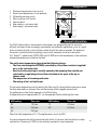
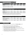
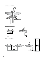
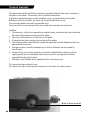
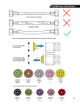
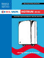
Domestic &
Commercial
Applications
Operating & Fitting Instructions
HOTRUN
35-90
ELECTRIC INSTANTANEOUS WATER HEATERS
saving water and energy
Contents
General information . . . . . . . . . . . . . . . . . . . . . . . . . . . . . . . . .
Technical data . . . . . . . . . . . . . . . . . . . . . . . . . . . . . . . . . . . . .
Safety instructions . . . . . . . . . . . . . . . . . . . . . . . . . . . . . . . . . .
Mounting instructions . . . . . . . . . . . . . . . . . . . . . . . . . . . . . . .
Water connection . . . . . . . . . . . . . . . . . . . . . . . . . . . . . . . . . .
Electric connection . . . . . . . . . . . . . . . . . . . . . . . . . . . . . . . . .
Initiation . . . . . . . . . . . . . . . . . . . . . . . . . . . . . . . . . . . . . . . . .
Maintenance . . . . . . . . . . . . . . . . . . . . . . . . . . . . . . . . . . . . . .
Troubleshooting . . . . . . . . . . . . . . . . . . . . . . . . . . . . . . . . . . . .
Terms of guarantee . . . . . . . . . . . . . . . . . . . . . . . . . . . . . . . . .
In this manual we explain to you how you can install your
Hotrun easy and safely. Keep this manual for future use.
The next user of the Hotrun water heater might need it.
2
3
4
4
5
5
7
8
8
8
10
Components
1.Maximum temperature cut-out (a or b)
2. Second max.temperature cut-out (optional)
3. Differential pressure switch
4. Micro-switches of dP switch
5. Terminal block
6. Blue marking = cold water inlet
7. Red marking = hot water outlet
1a
2
1b
3
4
5
6
7
General information
The ELWA Hotrun electric instantaneous water-heaters are designed for point of use (most
efficient and lowest water and energy consumption) and multipoint applications, such as a wash
basin or shower (or both), in fact all places where instant hot water is required. The heating of
the water is started instantly by opening a tap or valve connected to the hot water outlet.
The “Hotrun T” models meet AS/NZS 3500 and AS 3498 anti-scald requirements at the maximum
temperature performance stated on the label.
The outlet water temperature depends on the following factors:
- The flow rate through the HOTRUN, controlled by a fixed flow restrictor (supplied)
on or in the cold water inlet
-How far the hot water tap is actually opened or the incoming flow into the unit
restricted by a regulating valve or flow restriction in the spout of the tap or
shower head
- The temperature of incoming cold water
- The mixing of hot- and cold water
The hot water temperature rises by reducing the flow rate. By closing the hot-water tap or when
the flow drops below a minimum flow rate the heating will be stopped automatically.
The performance of the Hotrun depends on its kWatt rating.
A temperature rise of approximately 25° can be expected with the following flow rates:
kW loading:
Flow rate:
kW loading:
Flow rate:
3.5
1.9 l/min
7.2
4.0 l/min
4.6
2.5 l/min 9.0
5.0 l/min
6.0
3.0 l/min
When the inlet temperature is 25 °C the performance can rise by 50%.
The service temperature will be reached normally within 10 seconds after the Hotrun has been
switched on. A pressure of 100kPa is the minimum required for correct operation.
3
Technical specifications
Model
3546 60 72 90
Rating (kW)
3.5
4.6
6.0
7.2
9.0
Current (A)
16
20
25
2x16/32
2x20/40
Minimum pressure for all models: 1 bar / 100 kPa
Maximum pressure for all models: 10 bar /1MPa
Guaranteed Flow Rates at 37°C outlet temperature
l/min when 1.9
2.5
3.6
4.0
5.1
4.3
5.4
7.5
8.4
10.5
inlet temp. = 12°C
l/min when inlet temp. = 25°C
Electrical Approvals to European and Australian standards IEC & AS/NZS 60335:2:35
and Australian Plumbing Standard AS/NZS 3498 & 3500, WaterMark approval no. 40034
Selection/applications of Hotrun models (varies per State due to inlet temperature)
Hand basin
✔T
Hairdressers shampoo basins
✔T
✔T ✔T
Showers and basins
✔T
✔T
Commercial applications
✔
✔ ✔T ✔
✔T ✔
Safety instructions
Read these instructions for safety and installation carefully before starting to install!
Electrical connections have to be made by a qualified electrician.
Install the Hotrun as close as possible to the tap(s) in a frost-free space.
Make sure the power supply is shut off at all times installing or servicing a Hotrun.
Fit a service valve in the water supply to the Hotrun.
Do not operate the Hotrun in a “dry state”, the electrical power should not be switched on
before the Hotrun has been completely filled with water.
If the supply cord is damaged, it must be replaced by the manufacturer, its service agent or
similarly qualified persons in order to avoid a hazard.
4
Mounting instructions
The screws and plugs are supplied with the unit.
1. 2.
3.
Mark the position of the plugs according to the positional template allowing enough space
around the Hotrun to open the Hotrun by removing the top and bottom screws if needed
after installation.
Mount the unit using 2 screws.
Fit the top screw allowing it to stick out approximately 2-3 mm. Slide the securing
bracket onto the screw the Hotrun to the wall with the second screw in the lip sticking out
between the hot and cold water fittings.
Water connection
1.
2.
3.
4.
5.
6.
7.
8.
9.
The Hotrun has a pre-set minimal cold water supply operating pressure of 100 kPa. The
100 kPa pressure must remain under full flow conditions. When connecting the Hotrun to a
low pressure tank/rainwater system without pressure pump it is unlikely to operate. A larger pipe size on the cold water supply side might help in these circumstances.
Remove any flow restrictors in shower heads installed after the Hotrun, clean out the
aerators on tap outlets, and make sure these cause minimal backpressure to enable the
Hotrun to switch on and off. The outlet back-pressure needs to be less than the inlet supply
pressure, as the Hotrun switches on by a pressure differential switch.
If the minimal supply pressure is not secured at all times, the Hotrun can fail to switch on.
Ask our advice in this situation.
Connect to the water pipe-work only with the supplied flexible hoses, any other plumbing
fittings used on the water heater voids the warranty. All Hotrun fittings and flexible hoses
are WaterMark approved for the hot and cold water connections and have a flat seal
connection. By using the supplied flexible hoses avoids excessive tension on the Hotrun
fittings. Hand tighten the nuts and secure with ½ a turn with a spanner only.
A model specific flow controller is built in the cold water inlet or can be supplied separately
to fit to the cold water supply inlet fitting with each Hotrun.
The fitting with the blue marking is for the cold water inlet and the one with the
red marking is for the hot water drain and should not be mixed up.
Always use a ½˝ BSP (15mm) 100% bore ball valve on the cold water supply for service
purposes and temperature setting if needed after installation.
Important: After installation open the water tap to flush the device to release all air
from the coil and check all connections. Failing to do so shortens the live-span of the
electric elements.
Use the Hotrun-T 50°C for sanitary fixings for personal hygiene if limited temperatures are
required. The model Hotrun-T50 delivers a non-adjustable temperature of 50°C as mandatory by the plumbing code and as specified in AS/NZS3498. Further, a set temperature limited
model set at 40°C for hand wash basins and 45°C for education and aged care facilities is
available. When this manual was printed only for 50°C applications there is no need to install an additional thermostatic mixing valve as per AS3500.
5
Point of use installation
mains pressure
Point of use installation
Multipoint installation
6
Electric connection
1. 2.
3.
4.
5. 6. Australian and New Zealand Standards wiring rules and guidelines must be adhered to.
In most situations the installation of a 2-phase supply will be required for the Hotrun 72 and 90, to avoid voltage drop on a single phase supply/connection.
It is recommended to provide a dedicated circuit direct from the switchboard to each Hotrun.
The Hotrun has to be connected according to the applicable wiring diagram.
Check insulation resistance and proper earth continuity. Fill the unit with water, and only
then, switch the power on.
The applied wiring lugs on the wires end of the flexible cords must not be removed, these are essential to avoid arcking of the connections to the terminals. Removing the lugs voids the warrantee on the product.
Models 72 and 90 can be connected to a single phase power supply (32 resp. 40Amps) or 2-phase power supply (2x16A resp.2x20A). When connecting to a single phase circuit the 2 Live wires (brown and grey) can be joined in the supplied 2-way wire lug).
Hotrun up to 3.5 kWatt:
(single phase)
Hotrun 4.6 - 6.0 kWatt:
(single phase)
L1
L2
For single phase
Join L1 (brown)
and L2 (grey)
together in a lug
N1
N2
7
Initiation
Attention: Avoid overheating
Fill the unit completely with water before plugging it in or turning on the mains power supply.
For that purpose:
- Open the tap and wait until the water flows out from the spout without any air bubbles.
- Close the tap.
- Switch-on the mains supply.
- Hotrun is ready to use.
Maintenance
Due to its advanced design the Hotrun does not need any maintenance.
A damp cloth can be used for cleaning the cover.
Scouring and dissolving agents are not suitable.
Regularly clean scale from aerators and hose swivels.
Troubleshooting
Initial observations
The adequate supply and pressure of the water (min. 100kPa).
- Make sure the cold water inlet and the hot water outlet are not connected in reverse.
- The main switch or circuit breaker is switched on.
- The fuse/circuit breaker is not blown/triggered.
- Flow rate from cold supply is adequate for the installed Hotrun.
Problem 1
- The Hotrun does not switch on when opening the tap fully.
Cause
Usually attributed to water supply problems. Ensure the pressure on the cold water supply is
more than 100kPa, while the Hotrun is in use.
- Too much back pressure in outlets or shower heads after the Hotrun causing lack of
pressure differential over the Hotrun (backpressure through the cold).
- Wrong flow restrictor installed.
- Maximum temperature cut-out switches activated, due to air in the Hotrun not cleared
before switching on the electrical supply. Access to the thermal cut-out can only be
conducted by a suitable qualified tradesperson.
8
Troubleshooting
Remedy
- Fix the water pressure problems; remove any flow restrictors in outlets.
- Switch the electric power supply off, check that there is no power on any of the terminals.
- Seek electrical assistance to check power all the way to the elements.
Problem 2
- The water that is coming out of the Hotrun is not warm enough.
Cause
- The incoming water is very cold (below 12°C)
- The total flow is too high.
Remedy
- A flow restrictor should have been installed. If so, an additional ball valve in the water
supply to the Hotrun can enable you to reduce the flow and so increase the temperature (not for Hotrun-T models).
Problem 3
- The heating of water stops when trying to set the required temperature to a colder setting.
Cause
- Aerator/restrictor in nozzle of outlet causing too much back pressure.
- Incorrectly balanced flow restrictor in the supply line.
- Flow from the cold supply line is less than the requirements for the Hotrun.
Remedy
- Remove the restrictors in the tap or aerator fitting. Fit the appropriate restrictor to the cold
supply line for the Hotrun. Check that other taps or restrictors inbuilt into the supply line are
not effecting the flow or reducing the pressure too much.
Problem 4
- A Hotrun fitted in an upper floor situation of a building that is gravity fed, the Hotrun doesn’t switch on.
Cause
- The pressure is less than 100kPa. The pressure of water under gravity is 9kPa per metre, this
equates to approximately 30kPa per floor plus the height of the roof tank. On request we can
help to accommodate for most situations, sometimes just leaving out the flow restrictor from
the cold water inlet can be sufficient.
Remedy
- Remove all restrictors in the tap or aerator and use ‘star’ inserts in spout instead of aerator. Allowing full flow will often help in low pressure situations.
If the tests above indicate a fault then contact Elwa Technical Support
9
Technische
Terms of warranty
gegevens
On the provision that the installation instructions have been followed, Elwa gives a warranty of
two years on the Hotrun. The warranty starts at the date of purchase.
If despite our extensive products control complaints arise, you should inform your installer.
Before you contact the installer, we advise you to read the directions for use.
You can avoid needless discomfort and possible costs.
You can also fill in a service request form on our web-site www.elwa.com.au/service
Condition:
1. The warranty is valid only on presenting an original invoice, mentioning the date of purchase,
the name of the supplier and the type of the heater.
2. Elwa may void the warranty if the invoice is not legible.
3. If the production date is missing, the warranty will be voided.
4. The warranty will be voided from the moment the appliance has been tampered with or has
been modified in any way.
5. Damage caused as a result of improper use, or faulty installations are not covered by
this warranty.
6. Incorrect fitting, such as flow restrictor use incorrect, blocked filters in aerators and low
supply pressure are not warrantable items and may result in a charge from contractor
responsible for the call out service.
7. Warranty is void if flexible hoses supplied with this unit are not used.
This manual has been made with care.
Elwa retains the right to adjust product information in the future, for various reasons.
Built in flow control
10
Flexible hose instructions
For the range with built-in flow control:
1.9 l/min
hotrun
35
2.5 l/min
hotrun
46
3.0 l/min
hotrun
60
4.0 l/min
hotrun
72
5.0 l/min
hotrun
90
11
Elwa Pty Ltd
Adelaide
Australia
Phone: +61 8 8353 4040
www.elwa.com.au
Email: [email protected]
Elwa Pty Ltd
Auckland
New Zealand
Phone +64 21 280 173
www.elwa.co.nz
Email: [email protected]
Elwa BV
Amsterdam
The Netherlands
Tel.+31 20 436 1224
www.elwa.nl
Email: [email protected]
AS/NZS 3498
40034
version 2/2013
Approvals to Australian/New Zealand standards:
AS/NZS 60335.2.35, Certificate number CS/1274/S
AS/NZS 3498 & 3500
WaterMark approval number 40034
V2