1
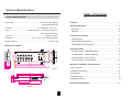
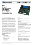
DP-640
USER’S MANUAL
No. 24-004-1632
Rev 1.1
No. 24-004-1632 Rev 1.1
All Rights Reserved
Technical Specifications
Table of Contents
Technical Specifications
Power Input ...............................................................2x15A, AC 120V~50/60Hz
2x20A (20A Rated Plug)
Line Cord.............................................................2 x 12AGWX3C VW-1 105° C
Load............................................ 1200W Channels 1~3, 1200W Channels 4~6
2400W (20A Rated Plug)
Features .........................................................................................1
General Instruction........................................................................2
Warnings.......................................................................................2
Cautions....................................................................................... 2
Fuse (x6) .............................................................................10A 250V, 5x20mm
Control and Functions.................................................................. 3
Dimensions ...........................................19.7” x 6.57” x 3.66” (500x167x93mm)
Overall Layout...............................................................................3
Weight (approx.) .........................................................................7.5 lbs.(3.4 kg)
Data & Power Connections.......................................................... 4
LED-display & Control buttons..................................................... 4
Dimensions in detail:
Operation Guide............................................................................ 5
Front
Function Mode 1: DMX Addressing.............................................. 5
6.34”
4.92”
6.89”
Function Mode 2: Patch Addressing.............................................6
Function Mode 3: Local Control....................................................7
Function Mode 4: Dimmer/Switch................................................ 8
17.73”
19.22”
19.70”
22.06”
3.23”
3.42”
3.65”
Side 1
Operation, Installation & Connections......................................... 9
Panic Function............................................................................... 9
Side 2
.47”
Connections....................................................................................9
Troubleshooting............................................................................ 10
2.56”
3.42”
1.14”
Installation & Mounting....................................................................9
17.33”
15.36”
Replacing Fuse(s)..........................................................................10
7.28”
14.57”
Technical Specifications ...............................................................11
Side 3
11
Features
Trouble Shooting
Troubleshooting
Thank you for purchasing the DP-640 dimmer pack. This product includes
the following features:
6 channel hybrid pack with dual Edison sockets per channel.
All six channels are user assignable between Dimmer & Switch modes.
6 channel LED’s indicate relevant channel activity.
4 function LED’s for DMX Address, Patch Address, Local Control
and Dimmer/Switch modes.
On board Local Control allows for dim intensity adjustment, from 0-100%,
for each individual channel.
Panic function dip switches.
Dual 15A/ AC120V Power line cords.
Digital LED-display.
Six 10A fuses. One per channel, AC120V, 5x20mm
Every effort has been made to design dependable and reliable products. New
products are constantly being designed to meet the needs of the entertainment
lighting industry. Your comments regarding our products and services are welcome.
Please send us an e-mail to [email protected] and let us know how we
can improve to better serve you.
It’s both a privilege and a pleasure serving you.
1
No Power to the pack:
Disconnect both main power line cords. Reconnect the line cords to
ensure proper connections. If the problem still persists, check the building
service panel and make sure the circuit breakers are on.
No Channel output:
Disconnect both main power line cords. Check the corresponding channel
fuse or fuses (see replacing fuses section). Replace if blown. Reconnect line
cords. If controlling via DMX, ensure that you are receiving DMX signal at the
pack. Indicator in the display should be flashing when signal is present. If
signal is not present, check the XLR connections from console or previous
fixture in line. If problem still persists, replace XLR cable between previous
device and pack and try again.
Undesired 100% channel output:
Flip all “PANIC” dip switches to the OFF position. If problem still persists,
check the “LOCAL CONTROL” settings and reset channels by pressing the
corresponding channel button two times so that the channel LED turns OFF.
Then press the “OK” button store the settings.
If you’ve tried the above and the unit continues to malfunction, please contact
ELATION customer service at (323) 582-3322, your unit will require service.
Once you describe your problem to the customer service representative, you
will be issued a return authorization number that must accompany the package
when sent in. Please write this RA# on the outside of the box with a black
marker and also write it on any packing list that may be included with the
package.
Replacing Fuse(s)
Fuse Replacement: Disconnect both main power line cords. Use a flat
head screwdriver to remove the fuse holder cap. Pull out the old fuse and
replace it with a new one of the exact same type. Replace the fuse cap with the
flat head screw driver. Do not over tighten as this may result in a broken and
unusable fuse holder.
10
Operation, Installation and Connections
PANIC Dip-Switches 1-6
The Panic feature allows you to select desired channels, via dip switches 1-6, to
be constantly on.
PANIC
ON
ON
MD
1 2 3 4 5 6
Flip the dip switches of the desired channels to the “ON” position.
The selected channels will output 100%.Note: When operating
with DMX control, corresponding channels with dip switches set
to “ON” will output 100% while channels with dip switches set to
the “OFF” position can be controlled from the DMX console.
Installation / Mounting
The DP-640 was designed to be mounted or free standing. It is recommended
that you use a suitable mounting clamp and safety cable when mounting to a
ceiling or rigging to a truss structure. There are two sets of threads on the DP-640.
These are in place for the mounting bracket. Use the bracket knobs and washers
to secure the mounting bracket to either side of the pack. For cooling purposes,
it is necessary to mount the pack so that air is free to circulate around the dimmer.
There should be at least 12 inches of clearance between the pack and anything
surrounding it.
General Instruction
This is a 6 channel portable dimmer/switch pack. Each channel can individually be
set to dim or switch as well as accept separate DMX Addresses. For your
convenience, each channel can manually be controlled via our simple to use,
digital display and function buttons. The Panic function allows you to select desired
channels to switch on constantly via the six dip switch settings. The unit is also
supplied with 3 & 5 pin XLR connectors. The aluminum case makes the DP-640
one the lightest portable dimmers of its kind.
To optimize performance of this product, please read the instructions carefully to
familiarize yourself with the basic operations.
Warnings
This unit must be earthed.
Keep the unit dry, do not expose it to water or high levels of humidity.
Do not allow for any flammable liquids to come in close contact with the unit.
Handle this unit carefully, any strong shock or vibration may result in malfunction.
Do not dismantle or modify this unit. There are no user serviceable parts inside.
Do not operate this unit if the internal components are exposed.
Only use an AC source that complies with the local building and electrical codes.
When replacing fuses, always replace with the exact same type.
Connections
The DP-640 is supplied with dual 15 Amp Edison plugs attached to 12 gauge
line cords. These cords should be connected to a service capable of suppling
15 amps per line cord and protected by a properly sized circuit breaker.
20 Amp Edison plugs can be used in place of the 15 Amp plugs to achieve a
higher load rating. In this case, the 20 amp plugs should be connected to a
service capable of supplying 20 amps per line cord and protected by a properly
sized circuit breaker. Lamp loads should be plugged into to the dual 15 Amp
Edison sockets which are supplied on the face of the pack. 3 & 5 pin XLR’s are
supplied for the input and output of the data link. Connect out of the console or
previous fixture in line and into the input of the DP-640. Connect out of the
DP-640 and into the input of next pack or fixture in line. It is recommended that
the last pack or fixture in line include a DMX terminator into the output. A DMX
terminator consists of a 120 ohm, 1/4 watt resistor soldered across pins 2 & 3
of either a 3 or 5 pin XLR connector.
9
Cautions
When unpacking, please check the unit for damages. Should you find something
wrong with the unit, please contact the dealer that you purchased it from
immediately.
All rights reserved. No part of this manual may be reproduced, in any form or
by any means, without permission in writing from Elation Professional.
Notice:
Specifications and improvements in the design of this product and this
manual are subject to change without prior notice.
2
Operation Guide
Control and Functions
Overall Layout
Function Mode 4: Dimmer/Switch
1
8
2
7
This menu option allows you to set the packs channels to dim or switch. Each
channel can individually be set to do one or the other. When a channel is set to
switch, then that channel will activate when the channel level exceeds 50%. When
a channel is set to dim, then that channels intensity can manually be adjusted from
0 to 100%.
Press the “Menu” button until the “Dimmer/Switch”
LED illuminates. The display will read either
or
depending on the current setting. The “C”
indicates “Channel”. The number that follows is the
packs channel number. The “d” indicates “Dim” and
“S” indicates “Switch”. In the example to the left, it
shows channel 2 is currently set to dim.
PANIC
3
ON
1
2
3
4
5
6
MD
1 2 3 4 5 6
DMX Address
DMX Signal
OK
Patch Address
4
5
6
9
1. Edison Output Sockets (1-6):
These are dual 120V. Edison sockets. Each socket is labeled with the
relevant channel number.
2. Fuse Holders (1-6):
These fuse holders each contain a 10A, AC120V, 5x20mm fuse. Each fuse
corresponds to the Edison output sockets above each fuse holder.
3. Threaded Openings:
These openings are supplied so the user can fasten the mounting bracket
to his or her desired side.
4. Bracket Knobs:
These knobs are used to fasten the hanging bracket to the chassis.
Local Control
Dimmer / Switch
MENU
1
2
3
4
5
6
PANIC
1
2
3
4
5
6
ON
MD
1 2 3 4 5 6
DMX Address
DMX Signal
Local Control
Dimmer / Switch
MENU
1
2
3
4
5
6
PANIC
1
2
3
4
5
6
ON
MD
1 2 3 4 5 6
DMX Address
5. Mounting Slots:
These slots are in place so the user could permanently mount the unit if
desired.
6. Connectors:
These are the DMX Input and Output connectors. There is a 3 & 5 pin Input
as well as a 3 & 5 pin Output. .
7. Control Section:
These buttons are used to adjust relevant settings within the display..
8. Mounting Bracket:
This mounting bracket is used to fasten the unit to a structure.
9. Power Inputs:
These supply power to the relevant channels when connected. Line cord 1
supplies power to channels 1-3 and line cord 2 supplies power to channels 4-6.
3
OK
Patch Address
(1) Select the channel that you wish to assign by
selecting from buttons 1-6. Only one channel
can be assigned at a time.
DMX Signal
OK
(2) Press the UP or Down button to change the
current setting. d = "Dim" / S = “Switch”
Patch Address
Local Control
Dimmer / Switch
MENU
1
2
3
4
5
6
PANIC
1
2
3
4
5
6
ON
MD
1 2 3 4 5 6
DMX Address
DMX Signal
OK
Patch Address
Local Control
Dimmer / Switch
MENU
1
2
3
4
5
(3) Press the “OK” button to confirm and save your
setting. The display will momentarily flash
confirming that your setting was stored. Repeat
steps one, two and three to assign additional
channels. These settings will be stored to memory.
6
8
Operation Guide
Control and Functions
Data & Power Connections
Function Mode 3: Local Control (Manual)
The Local Control option allows for the packs six channels to be manually
controlled via the on board buttons.
PANIC
ON
1
2
3
4
5
6
MD
1 2 3 4 5 6
DMX Address
DMX Signal
OK
Patch Address
Local Control
Dimmer / Switch
1
MENU
2
3
4
5
1
PANIC
3
2
5
4
2. DMX OUT:
3 & 5 Pin (female) output socket.
3. Power 1:
1200W Channels 1~3. 2400 watts
with 20 Amp rated plug.
4. Power 2:
1200W Channels 4~6. 2400 watts
with 20 Amp rated plug.
6
6
MD
1 2 3 4 5 6
DMX Address
1. DMX IN:
3 & 5 Pin (male) input socket.
Press the “Menu” button until the “Local Control”
LED illuminates. The display will read
This means that the channel 1 output level is
currently set to 0.
3
ON
2
1
DMX Signal
OK
Patch Address
4
LED-display & Control buttons
(1) Select the channel that you wish to manually
control by selecting from buttons 1-6. Only one
channel can be selected at a time.
12
1. LED-display: Shows the current
value and function mode- including
a DMX signal indicator.
11
Local Control
Dimmer / Switch
1
MENU
3
2
5
4
6
PANIC
ON
1
2
3
4
5
6
MD
1 2 3 4 5 6
1
1
PANIC
ON
2
3
4
5
6
MD
1 2 3 4 5 6
DMX Address
DMX Signal
OK
Patch Address
(2) Press the UP/ Down buttons to adjust the dim
level to your desired setting. The dim range is
from 000 to 100%.
DMX Address
2
3
4
5
10
DMX Signal
OK
Patch Address
9
Local Control
8
Dimmer / Switch
MENU
Local Control
1
2
3
4
Dimmer / Switch
1
MENU
2
3
4
5
2. DMX Address LED: This LED
illuminates when in DMX mode.
.
3. Patch Address LED: This LED
illuminates when in patch mode.
6
6
7
5
4. Local Control LED: This LED
illuminates when in manual control mode.
6
5. Dimmer/Switch LED: This LED
illuminates when assigning dim/switch
modes.
6. Menu Button: The menu button allows you to navigate through function modes.
PANIC
ON
1
2
3
4
5
6
MD
1 2 3 4 5 6
DMX Address
DMX Signal
OK
Patch Address
Local Control
Dimmer / Switch
MENU
7
1
2
3
4
5
6
(3) Press the “OK” button to confirm and save your
setting. The display will momentarily flash
confirming that your setting was stored. Repeat
steps one, two and three to manually set additional
channel levels and store them. These settings will
be stored to memory until you disengage the set
channels.
7. Channel Buttons 1~6: These buttons are used to select the relevant channel.
8. Down Button: This button decreases values and selects desired function modes.
9. OK Button: This button confirms and saves relevant settings.
10. UP Button: This button increases values and selects desired function modes.
11. Channel LED’s 1-6: Indicate output for the relevant channel.
12. Panic dip-switches: These switches are used to activate selected channels
to full on when DMX signal is not present.
4
Operation Guide
Operation Guide
*Note: Abbreviations within the display represent the following:
A=Address, C=Channel, d= Display, s=Switch.
Function Mode 2: Patch Address (Individual)
Press the MENU button to navigate through the menu options. Continually pressing
the MENU button will loop through the four options as illustrated below.
When in each function mode, its LED will light up.
PANIC
ON
1
2
3
4
5
6
MD
1 2 3 4 5 6
DMX Address
DMX Signal
OK
Patch Address
Local Control
Dimmer / Switch
Press
Press
Press
Menu button
Patch Address
Menu button
Local Control
Menu button
Dimmer/Switch
Press Menu button
DMX Address
Function Mode 1: DMX Address (Block)
PANIC
ON
1
2
3
4
5
6
MD
1 2 3 4 5 6
DMX Address
DMX Signal
OK
Patch Address
Local Control
Dimmer / Switch
MENU
PANIC
ON
1
1
2
2
3
3
4
4
5
5
6
(1) This function is used when setting the starting
DMX address channel for the pack. Use the
UP/Down ( / ) buttons to adjust to a
desired setting. The selected DMX channel will
be the starting DMX address for the pack. A total
of six DMX channels will be occupied by the
DP-640 in sequence, starting with the set channel.
MENU
1
2
3
4
5
6
Press the “MENU” button until the Patch Address
LED illuminates. The display will show you the
current patch setting for channel 1. For example,
if channel 1 was set to DMX channel 82, the
display would read the following:
The
number 1 in the display indicates channel 1 of the
pack. The next three digits indicate the current
DMX address for the selected channel.
Note: If you set a starting DMX address channel in the DMX address option, channel
one from the pack will assume that address channel and channels 2 through 6 will
automatically be assigned a sequential DMX channel based on the channel 1 address.
PANIC
ON
1
2
3
4
5
6
MD
1 2 3 4 5 6
DMX Address
DMX Signal
OK
Patch Address
Local Control
Dimmer / Switch
MENU
1
2
3
4
5
6
PANIC
1
2
3
4
5
6
(1) Select a channel button that you want to address.
Use the Up/Down buttons to adjust the channel
setting. The address can be set anywhere
between 001-512.
6
MD
1 2 3 4 5 6
ON
DMX Address
DMX Signal
OK
Patch Address
Local Control
Dimmer / Switch
MENU
1
2
3
4
5
6
(2) Press the “OK” button to confirm and save your
setting. The display will momentarily flash
confirming that your address was stored.
MD
1 2 3 4 5 6
DMX Address
DMX Signal
Patch Address
Local Control
Dimmer / Switch
MENU
5
OK
1
2
3
4
5
(2) Press the “OK” button to save your setting. The
display will momentarily flash confirming that
your patch setting has been stored. Repeat steps
one and two to patch additional channels.
6
6